EP0701732B1 - Process for producing packages for storage media - Google Patents
Process for producing packages for storage media Download PDFInfo
- Publication number
- EP0701732B1 EP0701732B1 EP95912069A EP95912069A EP0701732B1 EP 0701732 B1 EP0701732 B1 EP 0701732B1 EP 95912069 A EP95912069 A EP 95912069A EP 95912069 A EP95912069 A EP 95912069A EP 0701732 B1 EP0701732 B1 EP 0701732B1
- Authority
- EP
- European Patent Office
- Prior art keywords
- cardboard
- bottom portion
- carrier
- packaging
- holding
- Prior art date
- Legal status (The legal status is an assumption and is not a legal conclusion. Google has not performed a legal analysis and makes no representation as to the accuracy of the status listed.)
- Expired - Lifetime
Links
Images


Classifications
-
- G—PHYSICS
- G11—INFORMATION STORAGE
- G11B—INFORMATION STORAGE BASED ON RELATIVE MOVEMENT BETWEEN RECORD CARRIER AND TRANSDUCER
- G11B33/00—Constructional parts, details or accessories not provided for in the other groups of this subclass
- G11B33/02—Cabinets; Cases; Stands; Disposition of apparatus therein or thereon
- G11B33/04—Cabinets; Cases; Stands; Disposition of apparatus therein or thereon modified to store record carriers
- G11B33/0405—Cabinets; Cases; Stands; Disposition of apparatus therein or thereon modified to store record carriers for storing discs
- G11B33/0494—Cabinets; Cases; Stands; Disposition of apparatus therein or thereon modified to store record carriers for storing discs packages made by folding
-
- G—PHYSICS
- G11—INFORMATION STORAGE
- G11B—INFORMATION STORAGE BASED ON RELATIVE MOVEMENT BETWEEN RECORD CARRIER AND TRANSDUCER
- G11B33/00—Constructional parts, details or accessories not provided for in the other groups of this subclass
- G11B33/02—Cabinets; Cases; Stands; Disposition of apparatus therein or thereon
- G11B33/04—Cabinets; Cases; Stands; Disposition of apparatus therein or thereon modified to store record carriers
- G11B33/0405—Cabinets; Cases; Stands; Disposition of apparatus therein or thereon modified to store record carriers for storing discs
- G11B33/0411—Single disc boxes
- G11B33/0422—Single disc boxes for discs without cartridge
Definitions
- DE-U-9307309 already shows a packaging for a disc-shaped optical Storage disk, in particular a compact disc, which is constructed from cardboard. she consists essentially of individual cardboard layers glued on top of each other. adversely is the fact that especially when using inexpensive corrugated cardboard the end faces are exposed and are therefore not protected against damage. It is also difficult to write on the front.
- the method according to the invention can be used in various ways Bottom parts, cover parts and holding and receiving parts by different compilation produce the same packaging that are ideally adapted to the respective application, for example packaging for audio CDs with and without Package insert, for video CD's and CD-ROMs with and without Package insert or for floppy disks, especially 3 1/2 Inch disks. It is therefore possible to use less basic components, different types of packaging to manufacture the same packaging family, in particular, the different packaging can be the same Have external dimensions, advantageously those that the plastic packaging of audio CDs is common. For a leaflet is conveniently provided a cavity, in which the package insert in the usual format 12 cm x 12 cm space. Leave the different packaging basically all by the same or related Method steps of a method according to the invention produce.
- the recess 2 is through the inner edges of the top Cardboard layers 3 and 4 laterally limited, which together a holding and receiving part for the inserted floppy disk form.
- a recess can be formed with aligned openings whose depth is greater than the thickness of a cardboard layer, around two or more floppy disks on top of each other to be able to hold sideways.
- the recess 2 is in the Top view substantially rectangular, at least one side of the rectangle facing outwards, in the Top view preferably semicircular bulge 5 having. These bulges 5 allow a simple one Take out the in the recess 2 parallel to the Layers 3 and 4 are floppy disks the packaging.
- the carrier 1 shown in Fig. 1 consists essentially from three cardboard parts, which in FIGS. 2 to 4 are shown and according to that described below Procedure can be assembled.
- the outermost layer is a cardboard cover part 7, which has the blank shown in Fig. 2.
- the Cover part 7 has a part 6, which later Lid forms and a bottom section 8.
- the cover part 7 still has three further rags 9 and 10. The function of this rag will be described in more detail below.
- the cover part is advantageously made from a cardboard sheet punched out and in the same step on the future Folds 12 grooved. Die cutting can be done in two stages take place, first cutting knife Die cut the contour shown in Fig. 12 and then the cover part 7 is broken out by a counter punch becomes.
- the cover part can be punched out or cut can be printed in offset printing. If a box with a structure can be used, too a screen printing process can advantageously be used.
- the carrier 1 has a general with 15 designated holding part made of fine corrugated cardboard, which is shown in Fig. 4.
- holding part made of fine corrugated cardboard
- Fig. 4 In this part is in middle section an opening 16 with lateral bulges 5 punched out. In the two outer areas laterally open openings 17 are punched out.
- the holding and receiving part 15 points transversely to the longitudinal direction the corrugations on the corrugated cardboard corrugations 12 'on, around which the two side sections 4 Can be folded down 180 ° until they are at the middle part 3 issue.
- thermo-activatable Glue hot melt adhesive
- two types of adhesive at the same time to use namely a punctiform, thermo-activatable adhesive that holds immediately and one Surface-applied dispersion adhesive, which is permanent Ensures connection.
- This is particularly so an advantage in the case of rapid mechanical production.
- Both manual and machine The parts can be manufactured (cover part 7, base part 11, holding and receiving part 15) in upstream Prepare process steps and, for example, on Intermediate storage of stacks. From such stacks can then one part is removed manually or by machine and in the manner described above by folding, Cover and glue to a carrier for a storage medium are processed.
- the individual steps are relatively simple and can can therefore also be carried out mechanically.
- Part 7 has already been described.
- Part 11 shown is a corrugated cardboard Rectangle punched out, scratched along line 12 'and then the two parts 11a, 11b folded over to one to achieve stable bottom part, as shown in Fig. 7 in a Side view is shown.
- the openings 19 form recessed grips the CD. They are advantageously not on the edge of the carrier 1, which results in laterally continuous webs 25, which result in high stability and also when Do not buckle embossing.
- the change is there essentially in that protruding in the left Rag incisions 27 are provided, which allow drive the tab portion 9b onto the bottom portion 11c and the two side flap parts 9a to the higher ones Drive in floor parts 11d so that laterally an opening to the cavity 26 remains.
- FIGS. 10, 11, a laterally accessible cavity 26 even with a packaging for an audio CD like this is shown essentially in FIGS. 10, 11, be provided.
- the cover part can be that of FIG. 13 correspond to the bottom part of that of FIG. 14 and Holding and receiving part essentially that of FIG. 9, at most the right grip hole 5 'to an elongated Hole 5 "is enlarged to take out one to facilitate the booklet inserted in the cavity.
- a Holding and receiving part are used according to FIG. 9.
- the floor simply consists of a rectangular plate 29, as shown in FIGS. 18, 19.
- the cover part 17 has in addition to the lid 6 second cover 6a.
- a Holding and receiving part are glued according to FIG. 9 and then the covers 6, 6a can be folded up.
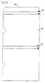
- the 20 shows the cut of a sleeve 18 which can also be punched out of cardboard.
- the case 18 has grooves 12 at the later folds and also has an adhesive tab 18a.
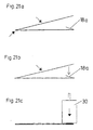
- the Adhesive flap 18a folded in, coated with adhesive and subsequently loaded with a weight 30, as in 21a to 21c.
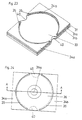
- the carrier of a packaging shown in FIG. 23 has a base body 31 made of corrugated cardboard 31a and one Liner 31b with a flat surface. On this surface is glued to two pieces of cardboard that provide the pads 35 for the CD. To this Cardboard pieces are two elevations 34a and 34b in shape of other pieces of cardboard glued, the thickness of which Thickness of the CD corresponds. The between the surveys 34a and 34b forms the free area of the cardboard pieces below the step-shaped edition 35 for the CD. The surface 33 of the intermediate layer 31b is opposite the edition 35 lowered (Fig. 23 and 25), so that the CD only lies outside the data area D.
- the elevations 34a and 34b are in shape on the Adjusted circumferential edge of the disk (CD) and point for this purpose, in the plan view, arcuate contact sections on.
- the arc radius of these system sections is preferably slightly larger than or substantially same as the radius of the disk to be inserted 36. This can be used as a centering device acting elevations 34a and 34b and the in the storage disk 36 inserted (see FIG. 24) there is a minor game. This makes it easier inserting and removing the CD since this in contrast to the usual crown sensors is no longer firmly clamped.
- the support surface 35 made of cardboard CD also with the sensitive bottom without Risk of damage to the data area D in a secure position rest.
- in the carrier 31 are in plan view two opposite indentations or recesses 40 provided. These run, as shown in FIG. 24, under the disk 36 so that the edge of the Storage plate 36 easier to grasp with two fingers is and thus the disk 36 simply from the carrier 31 can be lifted off.
- the two are on the rectangular base body 31 Cardboard pieces with the pads 35 and then the two Cardboard pieces 34a and 34b glued on. Because its outer edge on three sides with the base body, is a simple alignment of the glued parts on Base body 31 possible, so that a quick mechanical Manufacturing is ensured.
- the intermediate layer 31b can with appropriate training the top of the Layer 31a made of corrugated cardboard is even eliminated.
- the corrugated cardboard 31a allows high rigidity with low weight to achieve.
- the parts 31b, 34a and 34b can also be made of corrugated cardboard (less thick).
- the open sides of the corrugated cardboard can be used if necessary covered by a cover, not shown his.
- this unit can be Cardboard sleeve or box can be inserted.
- An embodiment of a case made of cardboard is in 22.
- Fig. 26 shows the manufacture of another particularly simple and precisely producible embodiment.
- a base bracket 31 On a base bracket 31 is a continuous Cardboard layer 32 glued on.
- the storage disk only outside its data area D supported, is simply by means of a stamp 41 Cardboard layer 32 in its central area with a provided circular indentation, so that in the middle Area a lowered surface 33 is present and remains in place after the cylindrical stamp has been removed again. Lowering the lowered Surface 33 opposite the step-shaped support 35 only needs to be minor. It is only a question of the Data area D of the disk 36 is not directly on lies on the box of the packaging.
Description
Die Erfindung betrifft ein Verfahren zur Herstellung von Verpackungen für Speichermedien, insbesondere optische Speicherplatten oder Disketten.The invention relates to a method for producing packaging for storage media, especially optical disks or floppy disks.
Weiters betrifft die Erfindung eine Verpackung für Speichermedien, insbesondere optische Speicherplatten öder Disketten, welche bevorzugt mit dem erfindungsgemäßen Verfahren herstellbar sind.Furthermore, the invention relates to a packaging for storage media, in particular optical Storage disks or diskettes, which preferably with the invention Processes can be produced.
Unter Speichermedien werden hier insbesondere optische Speicherplatten (wie zB Audio-Compact-Discs (CD's), CD-I's und CD-ROM's) sowie Disketten (wie zB 3½ Zoll-Disketten) verstanden, welche bei Datenverarbeitungsanlagen zum Einsatz kommen.Optical media (such as Audio compact discs (CD's, CD-I's and CD-ROMs) and floppy disks (such as 3½ inch floppy disks) understood which are used in data processing systems.
Solche Speichermedien, insbesondere die Audio-CD's, wurden bisher in Kunststoffteilen verpackt, die nur schwer wiederverwertbar sind und somit keine umweltverträgliche Verpackung darstellen.Such storage media, especially the audio CD's, have been used in plastic parts packaged that are difficult to recycle and therefore not environmentally friendly Show packaging.
Die DE-U-9307309 zeigt bereits eine Verpackung für eine scheibenförmige optische Speicherplatte, insbesondere eine Compact-Disc, die aus Karton aufgebaut ist. Sie besteht im wesentlichen aus übereinander geklebten einzelnen Kartonlagen. Nachteilig ist die Tatsache, daß vor allem bei der Verwendung von kostengünstiger Wellpappe die Stirnseiten frei liegen und damit gegen Beschädigungen nicht geschützt sind. Außerdem ist eine stirnseitige Beschriftung schwer möglich.DE-U-9307309 already shows a packaging for a disc-shaped optical Storage disk, in particular a compact disc, which is constructed from cardboard. she consists essentially of individual cardboard layers glued on top of each other. adversely is the fact that especially when using inexpensive corrugated cardboard the end faces are exposed and are therefore not protected against damage. It is also difficult to write on the front.
Die US-A-5,186,327 zeigt ebenfalls eine Verpackung für Compact-Discs aus Karton. Auch diese Verpackung des Standes der Technik weist im wesentlichen dieselben Nachteile auf.US-A-5,186,327 also shows packaging for compact discs made of cardboard. This prior art packaging also has essentially the same Disadvantages.
Eine Aufgabe der Erfindung besteht daher darin, ein Verfahren anzugeben, mit dem sich auf einfache Weise manuell oder maschinell umweltverträgliche Verpackungen herstellen lassen, die eine einfache Beschriftung erlauben und eine verbesserte Stabilität aufweisen.It is therefore an object of the invention to specify a method with which packaging that is environmentally friendly, either manually or mechanically Made that allow easy labeling and improved stability exhibit.
Das erfindungsgemäße Verfahren ist durch folgende Schritte gekennzeichnet:
Die erfindungsgemäße Verpackung für Speichermedien, insbesondere optische Speicherplatten oder Disketten, mit einem Träger aus mindestens einer Lage Karton mit einer Vertiefung zum Einlegen des Speichermediums, wobei der Träger vorzugsweise in eine beidseitig offene Hülle aus Karton einschiebbar ist, und wobei der Träger für das Speichermedium einen ein- oder mehrlagigen Bodenteil aus Karton und einen darüberliegenden, mit einer Vertiefung versehenen, ebenfalls ein- oder mehrlagigen Halteteil aus Karton aufweist, ist dadurch gekennzeichnet, daß der Träger weiters einen Umschlagteil aufweist, der unter dem Bodenteil verläuft und von dort um die Ränder des Bodenteils und zumindest teilweise des Halteteiles nach oben umgeschlagen und verklebt ist.The packaging according to the invention for storage media, in particular optical storage disks or floppy disks, with a carrier made from at least one layer of cardboard a recess for inserting the storage medium, the carrier preferably can be inserted into a cardboard sleeve that is open on both sides, and the carrier for the storage medium has a single or multi-layer base made of cardboard and an overlying one with a recess, also single or multi-layer holding part made of cardboard, is characterized in that the carrier further a Envelope part that runs under the bottom part and from there around the edges of the bottom part and at least partially of the holding part turned up and is glued.
Durch die Verwendung von Karton kann der Einsatz von weniger umweltverträglichem Kunststoff vermieden werden. Dennoch lassen sich durch das erfindungsgemäße Verfahren Verpackungen rasch und problemlos auch maschinell herstellen. Diese Verpackungen zeichnen sich durch einen stabilen exakten Aufbau, eine gute Schutzwirkung für die darin verpackten Speichermedien, eine einfache Handhabung und schließlich durch einen optisch ansprechenden Eindruck aus.By using cardboard, the use of less environmentally friendly Plastic can be avoided. Nevertheless, the inventive Process Manufacturing packaging quickly and easily by machine. This packaging are characterized by a stable, exact structure and a good protective effect for the storage media packed in it, easy handling and finally by a visually appealing impression.
Der um die Ränder des Bodenteiles und Halte- und Aufnahmeteiles umgeschlagene Umschlagteil deckt die seitlichen Ränder dieser Teile ab, was vor allem bei der Verwendung von Wellkarton (Wellpappe) von Vorteil ist, einerseits um das Eindringen von Schmutz und Feuchtigkeit in die offenen Kanäle der Wellpappe zu vermeiden, andererseits um die mechanische Stabilität des Randbereiches der Wellpappe zu erhöhen und außerdem den optischen Eindruck zu verbessern. Die Verwendung von Wellkarton bzw. Wellpappe hat den Vorteil, daß dieser bei größerer Dicke ein geringes Gewicht aufweist und sich leicht verarbeiten läßt, insbesondere kann nach der Vornahme von Ritzungen der Wellkarton leicht gefaltet werden. Um eine gerade Faltstelle zu erreichen, ist es besonders vorteilhaft, die Ritzung quer zum Wellenlauf des Wellkartons vorzunehmen.The one folded over around the edges of the bottom part and holding and receiving part Envelope part covers the side edges of these parts, especially when used of corrugated cardboard (corrugated cardboard) is advantageous on the one hand to prevent the penetration of To avoid dirt and moisture in the open channels of the corrugated cardboard on the other hand to increase the mechanical stability of the edge area of the corrugated cardboard and also to improve the visual impression. The use of Corrugated cardboard or corrugated cardboard has the advantage that it is slightly thicker Has weight and is easy to work with, especially after making can be easily folded by cracks in the corrugated cardboard. A straight fold To achieve it, it is particularly advantageous to score the score across the corrugation of the corrugated cardboard make.
Mit dem erfindungsgemäßen Verfahren lassen sich unter Verwendung verschiedenartiger
Bodenteile, Umschlagteile und Halte- und Aufnahmeteile durch unterschiedliche
Zusammenstellung
derselben Verpackungen herstellen, die
an den jeweiligen Einsatzzweck ideal angepaßt sind,
beispielsweise Verpackungen für Audio-CD's mit und ohne
Beipackheft, für Video-CD's und CD-ROM's mit und ohne
Beipackheft oder für Disketten, insbesondere 3 1/2
Zoll-Disketten. Es ist somit möglich, unter Verwendung
weniger Grundkomponenten verschiedenartigste Verpackungen
ein und derselben Verpackungsfamilie herzustellen,
insbesondere können die verschiedenen Verpackungen dieselben
Außenmaße aufweisen, vorteilhaft jene, die bei
den Plastikverpackungen von Audio-CD's üblich ist. Für
ein Beipackheft wird günstigerweise ein Hohlraum vorgesehen,
in dem das Beipackheft in üblichem Format 12 cm
x 12 cm Platz hat. Die verschiedenen Verpackungen lassen
sich grundsätzlich alle durch gleiche bzw. verwandte
Verfahrensschritte eines erfindungsgemäßen Verfahrens
herstellen.The method according to the invention can be used in various ways
Bottom parts, cover parts and holding and receiving parts by different
compilation
produce the same packaging that
are ideally adapted to the respective application,
for example packaging for audio CDs with and without
Package insert, for video CD's and CD-ROMs with and without
Package insert or for floppy disks, especially 3 1/2
Inch disks. It is therefore possible to use
less basic components, different types of packaging
to manufacture the same packaging family,
in particular, the different packaging can be the same
Have external dimensions, advantageously those that
the plastic packaging of audio CDs is common. For
a leaflet is conveniently provided a cavity,
in which the package insert in the
Weitere Vorteile und Einzelheiten der Erfindung werden anhand der nachfolgenden Figurenbeschreibung näher erläutert.
- Fig. 1
- zeigt eine perspektivische Ansicht eines Ausführungsbeispieles einer erfindungsgemäßen Verpackung für zwei 3 1/2 Zoll-Disketten
- Fig. 2
- zeigt den Zuschnitt eines Umschlagteiles, wie er bei der Verpackung gemäß Fig. 1 zum Einsatz kommt,
- Fig 3
- zeigt den Zuschnitt eines Bodenteiles für eine Verpackung gemäß Fig. 1,
- Fig. 4
- zeigt den Zuschnitt eines Halte- und Aufnahmeteiles für eine Verpackung gemäß Fig. 1,
- Fig. 5
- zeigt den Träger einer Verpackung für eine Video-CD oder CD-ROM in perspektivischer Darstellung,
- Fig. 6
- zeigt den Zuschnitt des Bodenteiles für eine Verpackung gemäß Fig. 5 in einer Draufsicht,
- Fig. 7
- zeigt den zusammengefalteten Bodenteil der Fig. 6 im Querschnitt,
- Fig. 8
- zeigt den Zuschnitt eines Halte- und Aufnahmeteiles einer Verpackung gemäß Fig. 5,
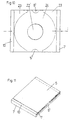
- Fig. 9
- zeigt einen Halte- und Aufnahmeteil für die Verpackung einer Audio-CD, wie sie in Fig. 11 dargestellt ist,
- Fig. 10
- zeigt eine Draufsicht auf den Trägerteil dieser Verpackung (bei weggelassenem Klappdeckel),
- Fig. 11
- zeigt eine perspektivische Ansicht des Trägerteiles einer Verpackung für eine Audio-CD mit geschlossenem Klappdeckel,
- Fig. 12
- zeigt eine perspektivische Darstellung eines Trägers einer Verpackung für eine Video-CD oder CD-ROM mit einem Hohlraum für ein Beipackheft,
- Fig. 13
- zeigt den Zuschnitt des Umschlagteiles für den in Fig. 12 gezeigten Träger,
- Fig. 14
- zeigt den Zuschnitt für den Bodenteil des Trägers der Fig. 12,
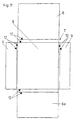
- Fig. 15
- zeigt den fertigen Bodenteil in einer Seitenansicht,
- Fig. 16
- zeigt den Träger einer Verpackung für eine Audio-CD mit einem Hohlraum für ein Beipackheft in perspektivischer Darstellung mit geöffnetem Deckel,
- Fig. 17
- zeigt den Umschlagteil einer Variante für eine Audio-CD im Zuschnitt,
- Fig. 18
und 19 - zeigen den Bodenteil in einer Draufsicht und einer Seitenansicht,
- Fig. 20
- zeigt den Zuschnitt für eine Hülle, in die ein Träger, wie er in den Fig. 1, 5, 11, 12 oder 16 dargestellt ist, eingeschoben werden kann,
- Fig. 21a bis 21c
- zeigen den Verfahrensablauf zur Herstellung einer Hülle,
- Fig. 22
- zeigt die fertige Hülle in einer perspektivischen Darstellung,
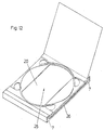
- Fig. 23
- zeigt einen Träger eines Ausführungsbeispieles einer erfindungsgemäßen Verpackung ohne eingelegte Speicherplatte (CD),
- Fig. 24
- zeigt eine Draufsicht auf den Träger mit eingelegter CD,
- Fig. 25
- zeigt einen Schnitt nach A-A der Fig. 24,
- Fig. 26
- zeigt die Herstellung eines weiteren Beispiels im Schnitt.
- Fig. 1
- shows a perspective view of an embodiment of a packaging according to the invention for two 3 1/2 inch disks
- Fig. 2
- shows the cut of an envelope part as it is used in the packaging according to FIG. 1,
- Fig 3
- shows the cut of a bottom part for a packaging according to FIG. 1,
- Fig. 4
- shows the cut of a holding and receiving part for a package according to FIG. 1,
- Fig. 5
- shows the carrier of a package for a video CD or CD-ROM in a perspective view,
- Fig. 6
- shows the cut of the bottom part for a package according to FIG. 5 in a plan view,
- Fig. 7
- shows the folded bottom part of FIG. 6 in cross section,
- Fig. 8
- shows the cut of a holding and receiving part of a package according to FIG. 5,
- Fig. 9
- shows a holding and receiving part for the packaging of an audio CD, as shown in Fig. 11,
- Fig. 10
- shows a plan view of the carrier part of this packaging (with the hinged lid omitted),
- Fig. 11
- shows a perspective view of the carrier part of a packaging for an audio CD with a closed hinged lid,
- Fig. 12
- shows a perspective view of a carrier of a packaging for a video CD or CD-ROM with a cavity for an insert booklet,
- Fig. 13
- shows the cut of the envelope part for the carrier shown in Fig. 12,
- Fig. 14
- shows the cut for the bottom part of the carrier of Fig. 12,
- Fig. 15
- shows the finished bottom part in a side view,
- Fig. 16
- shows the carrier of a packaging for an audio CD with a cavity for an insert booklet in a perspective view with the lid open,
- Fig. 17
- shows the cover part of a variant for an audio CD in the blank,
- 18 and 19
- show the bottom part in a plan view and a side view,
- Fig. 20
- shows the blank for a sleeve into which a carrier, as shown in FIGS. 1, 5, 11, 12 or 16, can be inserted,
- 21a to 21c
- show the process sequence for producing a shell,
- Fig. 22
- shows the finished shell in a perspective view,
- Fig. 23
- shows a carrier of an embodiment of a packaging according to the invention without an inserted storage disc (CD),
- Fig. 24
- shows a plan view of the carrier with a CD inserted,
- Fig. 25
- shows a section along AA of FIG. 24,
- Fig. 26
- shows the production of another example in section.
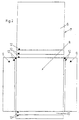
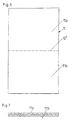
Der in Fig. 1 dargestellte Träger 1 einer erfindungsgemäßen
Verpackung für Disketten besteht aus mehreren
verklebten Kartonlagen. In der Mitte ist erfindungsgemäß
eine Vertiefung 2 ausgebildet, in die beim dargestellten
Ausführungsbeispiel zwei übereinanderliegende
3 1/2 Zoll-Disketten mit geringem seitlichen Spiel eingelegt
werden können.The
Die Vertiefung 2 wird durch die Innenränder der oberen
Kartonlagen 3 und 4 seitlich begrenzt, welche zusammen
einen Halte- und Aufnahmeteil für die eingelegte Diskette
bilden.The
Über zwei oder mehrere übereinanderliegende Lagen 3,4
mit fluchtenden Öffnungen kann eine Vertiefung gebildet
werden, deren Tiefe größer ist als die Dicke einer Kartonlage,
um auch zwei oder mehrere Disketten übereinander
seitlich halten zu können.Over two or
Wie die Fig. 1 zeigt, ist die Vertiefung 2 in der
Draufsicht im wesentlichen rechteckig, wobei zumindest
eine Rechteckseite eine nach außen weisende, in der
Draufsicht vorzugsweise halbkreisförmige Ausbuchtung 5
aufweist. Diese Ausbuchtungen 5 erlauben ein einfaches
Herausnehmen der in der Vertiefung 2 parallel zu den
Schichten bzw. Lagen 3 und 4 liegenden Disketten aus
der Verpackung.1 shows, the
Über einen klappbaren Klappdeckel 6, der am Träger 1
gelagert ist, kann die Vertiefung 2 oben abgedeckt werden.
Nach öffnen des Deckels 6 läßt sich die Diskette
bzw. lassen sich die Disketten leicht entnehmen.Via a hinged hinged
Der in Fig. 1 dargestellte Träger 1 besteht im wesentlichen
aus drei Kartonteilen, die in den Fig. 2 bis 4
dargestellt sind und gemäß dem im folgenden beschriebenen
Verfahren zusammengebaut werden.The
Die äußerste Lage ist ein Umschlagteil 7 aus Karton,
der den in Fig. 2 dargestellten Zuschnitt aufweist. Der
Umschlagteil 7 weist einen Teil 6 auf, der später den
Deckel bildet und einen Bodenabschnitt 8. Neben dem
einseitig freien Lappen, der den Klappdeckel 6 für die
Vertiefung 2 bildet, weist der Umschlagteil 7 noch drei
weitere Lappen 9 und 10 auf. Die Funktion dieser Lappen
wird im folgenden noch näher beschrieben.The outermost layer is a
Der Umschlagteil wird vorteilhaft aus einem Kartonbogen
ausgestanzt und im selben Arbeitsschritt an den zukünftigen
Faltstellen 12 gerillt. Das Ausstanzen kann zweistufig
erfolgen, wobei zunächst Schneidemesser der
Stanze die in Fig. 12 dargestellte Kontur anschneiden
und dann der Umschlagteil 7 durch eine Gegenstanze ausgebrochen
wird. Der Umschlagteil kann vor Ausstanzen
oder Ausschneiden im Offsetdruck bedruckt werden. Falls
ein Karton mit einer Struktur verwendet wird, kann auch
vorteilhaft ein Siebdruckverfahren verwendet werden. The cover part is advantageously made from a cardboard sheet
punched out and in the same step on the future
Folds 12 grooved. Die cutting can be done in two stages
take place, first cutting knife
Die cut the contour shown in Fig. 12
and then the
Als weiteren Teil weist der Träger 1 einen Bodenteil 11
auf, der in Fig. 3 dargestellt ist. Dieser Bodenteil 11
besteht aus einem rechteckigen Wellkarton (Wellpappe),
der entlang der Linie 12' geritzt ist, um entlang dieser
Linie zusammengefaltet zu werden. In dem Teil 11a
ist eine im wesentlichen rechteckige Ausnehmung 13 mit
halbkreisförmigen Ausbuchtungen 5 ausgestanzt. Im anderen
Teil 11b wird mittels eines Prägestempels durch
Prägen in den Karton ein abgesenkter Bereich 14 erzeugt.
Die Tiefe dieses abgesenkten Bereiches 14 zusammen
mit der Dicke des Teiles 11a und der Dicke der beiden
Schichten 3 und 4 ergibt dann beim dargestellten
Ausführungsbeispiel genau die Höhe von zwei 3 1/2 Zoll-Disketten,
sodaß diese bündig mit der Oberfläche des
Trägers 1 unter dem Deckel 6 abschließen.As a further part, the
Als weiteren Teil weist der Träger 1 einen allgemein
mit 15 bezeichneten Halteteil aus feiner Wellpappe auf,
der in Fig. 4 dargestellt ist. In diesem Teil ist im
mittleren Abschnitt eine Öffnung 16 mit seitlichen Ausbuchtungen
5 ausgestanzt. In den beiden äußeren Bereichen
werden seitlich offene Öffnungen 17 ausgestanzt.
Der Halte- und Aufnahmeteil 15 weist quer zur Längsrichtung
der Wellen des Wellkartons verlaufende Ritzungen
12' auf, um die die beiden Seitenabschnitte 4 um
180° umgeklappt werden können, bis sie am Mittelteil 3
anliegen.As a further part, the
Die Teile der Fig. 2 bis 4 werden wie folgt zusammengesetzt:
Nachdem der in Fig. 3 gezeigte Bodenteil 11 um
die Ritzungslinie 12' um 180° zusammengefaltet worden
ist, wird er auf den Bodenabschnitt 8 des Umschlagteiles
7 aufgeklebt. The parts of Figures 2 to 4 are composed as follows:
After the
Dabei ist es möglich, den Umschlagteil 7 über einer
Senke anzuordnen, die etwas größer ist als die Außenabmessungen
des Bodenabschnittes 8 bzw. des Bodenteiles
11. Hierauf kann man den Bodenteil von oben auf den Bodenabschnitt
8 des Umschlagteiles 7 drücken, wobei sich
dieser in die Senke bewegt und dabei die vier Lappen 6,
9, 10 am Rand der Senke automatisch senkrecht nach oben
geklappt werden und somit für eine Weiterverarbeitung
bereits eine ideale Stellung haben.It is possible to cover
Es können nun die beiden seitlichen Lappen 9 um die
entlang der Linien 12 vorgerillten Stellen oben eingeschlagen
werden und decken somit die seitlichen Ränder
des Bodenteiles 11 ab.It can now the two
Nun wird die Oberseite der umgeschlagenen Lappen 9 mit
Klebstoff bestrichen und der zusammengefaltete Halteteil
15 aufgeklebt. Zum Schluß wird der Lappen 10
sowohl um den Bodenteil 11, als auch um den Halteteil
15 oben eingeschlagen und dort festgeklebt. Er deckt
somit die Stirnkante vollständig ab, wie dies in Fig. 1
gezeigt ist. Auf der anderen Seite geschieht ähnliches.
Hier wird der Lappen mit dem Deckel 6 ebenfalls nach
oben umgeschlagen und oben festgeklebt.Now the top of the folded
Der Träger kann dann einen elektromotorisch betriebenen
Preßteppich durchlaufen, bis alle Kleber ausgehärtet
sind. Schließlich kann der Träger 1 bei zugeklapptem
Deckel in eine Hülle, wie sie in Fig. 22 gezeigt ist,
eingeschoben werden. Diese Hülle 18 verhindert ein öffnen
des Deckels 6 und schützt somit die im Träger untergebrachten
Disketten zusätzlich.The carrier can then be an electric motor
Run through the press carpet until all glue has hardened
are. Finally, the
Um die Aushärtzeit zu verringern, können thermoaktivierbare
Kleber (Schmelzkleber = Hotmelt) verwendet
werden. Allerdings hat sich gezeigt, daß solche Kleber
eine weniger dauerhafte Verbindung ergeben. Deshalb ist
es besonders vorteilhaft, gleichzeitig zwei Klebertypen
zu verwenden, nämlich einen punktförmig aufgetragenen,
thermoaktivierbaren Kleber, der sofort hält und einen
flächig aufgetragenen Dispersionskleber, der eine dauerhafte
Verbindung sicherstellt. Dies ist insbesondere
bei der maschinellen raschen Fertigung von Vorteil.
Sowohl bei der manuellen als auch bei der maschinellen
Fertigung lassen sich die Teile (Umschlagteil 7, Bodenteil
11, Halte- und Aufnahmeteil 15) in vorgeschalteten
Verfahrensschritten vorfertigen und beispielsweise auf
Stapeln zwischenspeichern. Von solchen Stapeln kann
dann händisch oder maschinell jeweils ein Teil abgenommen
und auf die oben beschriebene Weise durch Falten,
Umschlagen und Verkleben zu einem Träger für ein Speichermedium
verarbeitet werden. Die einzelnen Teilschritte
sind dabei verhältnismäßig einfach und können
daher auch maschinell durchgeführt werden.In order to reduce the curing time, thermo-activatable
Glue (hot melt adhesive) used
become. However, it has been shown that such glue
result in a less permanent connection. Therefore
it is particularly advantageous to use two types of adhesive at the same time
to use, namely a punctiform,
thermo-activatable adhesive that holds immediately and one
Surface-applied dispersion adhesive, which is permanent
Ensures connection. This is particularly so
an advantage in the case of rapid mechanical production.
Both manual and machine
The parts can be manufactured (cover
Während die Fig. 1 bis 4 einen Träger einer Verpackung
für zwei 3 1/2 Zoll-Disketten gezeigt haben, ist in den
Fig. 5 bis 8 ein Träger 1 für Video-CD's oder CD-ROM's
mit empfindlichem Datenbereich beschrieben. Auch dieser
in Fig. 5 gezeigte Träger 1 ist erfindungsgemäß aus einem
Bodenteil 11 (Fig. 6, 7), einem Halte- und Aufnahmeteil
15 (Fig. 8) und einem Umschlagteil 7 aufgebaut,
wobei der Umschlagteil 7 genau gleich wie der in Fig. 2
ausgebildet sein kann.1 to 4 a carrier of a package
for two 3 1/2 inch floppy disks is shown in the
5 to 8 a
Auch der Herstellungsablauf ist gleich wie bei dem in
den Fig. 1 bis 4 beschriebenen Ausführungsbeispiel.
Zunächst werden die einzelnen Teile 7, 11, 15 gebildet.
Der Teil 7 wurde bereits beschrieben. Bei dem in Fig. 6
gezeigten Teil 11 wird aus einem Wellkarton ein
Rechteck ausgestanzt, entlang der Linie 12' geritzt und
dann die beiden Teile 11a, 11b umgefaltet, um einen
stabilen Bodenteil zu erlangen, wie er in Fig. 7 in einer
Seitenansicht dargestellt ist.The manufacturing process is also the same as in
1 to 4 embodiment described.
First, the
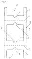
Der in Fig. 8 im Zuschnitt dargestellte Halte- und Aufnahmeteil
15 wird aus einem feinen Microwellkarton ausgestanzt
und entlang der Linien 12' gerillt. Beim Ausstanzen
werden auch die Öffnungen 19 sowie die große
zentrale Öffnung 20 ausgestanzt. Beim Ausstanzen oder
bei einem darauffolgenden Arbeitsschritt kann mit Hilfe
eines Prägestempels ein innerhalb der Linien 21 liegender
kreisförmiger Bereich 22 im Karton eingedrückt werden,
also ein gegenüber der sonstigen Oberfläche abgesenkter
Bereich erzeugt werden.The holding and receiving part shown in the blank in FIG. 8
15 is punched out of a fine microwell cardboard
and grooved along lines 12 '. When punching out
the
Vor der Montage des Teiles 15 der Fig. 8 werden die
beiden seitlichen Lappen 23 auf den Mittelteil 24 umgeschlagen
und gegebenenfalls festgeklebt.Before assembly of
Der Zusammenbau zum Träger gemäß Fig. 5 erfolgt dann
wieder durch Auflegen des Bodenteiles 11 auf den Umschlagteil
7 durch anschließendes Einklappen und Festkleben
der Lappen 9 und darauffolgendes Festkleben des
Aufnahme- und Halteteiles 15 der Fig. 8, worauf
schließlich der Lappen 10 und der mit der Klappe 6 versehene
Lappen des Umschlagteiles 7 auf der Oberseite
des Aufnahme- und Halteteiles 15 (genauer auf dessen
Lappen 23) festgeklebt wird.The assembly to the carrier according to FIG. 5 then takes place
again by placing the
Zwischen den Teilen 23 ergibt sich somit eine gegenüber
deren Oberfläche abgesenkte Vertiefung, in die eine optische
Speicherplatte, insbesondere eine Video-CD oder
CD-ROM eingelegt werden kann. Die bogenförmigen Abschnitte
der Lappen 23 halten dabei die CD zentriert im
Träger 1. Die CD liegt nur mit ihrem äußersten Rand am
Mittelteil 24 des Halte- und Aufnahmeteiles 15 auf. Im
dazwischenliegenden Bereich befindet sich die Öffnung
20 und innerhalb der Linie 21 der durch Prägen abgesenkte
Bereich 22. Durch die große Öffnung 20 kann das
Material beim Prägen leicht verdrängt werden.There is thus an opposite between the
Die Öffnungen 19 bilden Griffmulden zum Herausnehmen
der CD. Sie liegen vorteilhaft nicht am Rand des Trägers
1, womit sich seitlich durchgehende Stege 25 ergeben,
die eine hohe Stabilität ergeben und auch beim
Prägen nicht einknicken.The
Insgesamt ist es mit der in Fig. 5 gezeigten Verpackung
möglich, eine CD zu verpacken, ohne daß deren empfindlicher
Datenbereich direkt auf Karton aufliegt. Dazu
muß nur der Außendurchmesser des abgesenkten Bereiches
22 größer sein als der mit Daten versehene Bereich der
optischen Speicherplatte.Overall, it is with the packaging shown in Fig. 5
possible to pack a CD without making it more sensitive
Data area lies directly on cardboard. To
only the outer diameter of the lowered
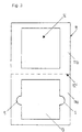
Verwendet man anstelle des in Fig. 8 gezeigten Halte-
und Aufnahmeteiles 15 den Aufnahmeteil 15 gemäß Fig. 9,
so erhält man mit einem Bodenteil, gemäß den Fig. 6, 7,
und einem Umschlagteil, gemäß Fig. 2, einen Träger, der
insbesondere für die Verpackung einer Audio-CD geeignet
ist. Dieser Träger ist in den Fig. 10, 11 dargestellt.
Er weist eine ebene Auflage 24 für die CD auf. Ein
mittlerer kreisförmiger Bereich 22' ist abgesetzt, weil
die Audio-CD's üblicherweise an der Unterseite einen
Grat aufweisen, der vorsteht. Durch die Absenkung 22'
wird erreicht, daß die CD trotz dieses Grates satt auf
der Fläche 24 aufliegt und von den seitlichen Erhebungen
23 zentriert gehalten werden kann. Zum Herausnehmen
sind zur Seite hin offene Ausnehmungen 5' vorgesehen.If instead of the holding device shown in FIG.
and receiving
Die in Fig. 12 dargestellte Verpackung unterscheidet
sich von der gemäß Fig. 5 im wesentlichen darin, daß
sie im Bodenteil einen seitlich offenen Hohlraum 26
aufweist, in dem ein Beipackheft einschiebbar ist. Der
Hohlraum ist über die große zentrale Öffnung 20 auch
von oben zugänglich, womit sich auch ein vollständig
eingeschobenes Heft nach außen schieben läßt. Um den
Hohlraum zu bilden, weist der Bodenteil gemäß den Fig.
14, 15 neben einem mittleren Abschnitt 12c zwei schmale
äußere Abschnitte 11d auf, die entlang von Ritzungen
12' hochklappbar sind, um einen Bodenteil gemäß Fig. 15
zu bilden. Zwischen den beiden schmalen Teilen 11d ist
nun oberhalb des Teiles 11c Platz für ein Beipackheft.
Abgesehen vom Bodenteil 11 muß auch der Umschlagteil 7,
ausgehend von der Fig. 2, geringfügig geändert werden,
wie dies in Fig. 13 dargestellt ist. Die Änderung besteht
im wesentlichen darin, daß im linken abstehenden
Lappen Einschnitte 27 vorgesehen sind, die es erlauben,
den Lappenteil 9b auf den Bodenteil 11c einzuschlagen
und die beiden seitlichen Lappenteile 9a auf die höherliegenden
Bodenteile 11d einzuschlagen, sodaß seitlich
eine Öffnung zum Hohlraum 26 bleibt.The packaging shown in Fig. 12 differs
5 essentially in that
they have a laterally
Bei der Herstellung einer solchen Verpackung ist es
zweckmäßig, in den Platz für den Hohlraum 26 bzw. des
Beipackheftes zwischenzeitlich eine Einlage einzulegen,
um zu verhindern, daß beim Verkleben und Verpressen der
Hohlraum zusammengedrückt wird. Die Einlage wird nachher
aus der verklebten Verpackung wieder entfernt.It is in the manufacture of such packaging
expedient, in the space for the
Gemäß Fig. 16 kann ein seitlich zugänglicher Hohlraum
26 auch bei einer Verpackung für eine Audio-CD, wie sie
im wesentlichen in den Fig. 10, 11 dargestellt ist,
vorgesehen sein. Der Umschlagteil kann dem der Fig. 13
entsprechen, der Bodenteil dem der Fig. 14 und der
Halte- und Aufnahmeteil im wesentlichen dem der Fig. 9,
wobei allenfalls das rechte Griffloch 5' zu einem länglichen
Loch 5" vergrößert ist, um die Herausnahme eines
in den Hohlraum eingelegten Heftes zu erleichtern. 16, a laterally
Bei dem Ausführungsbeispiel gemäß Fig. 17 kann ein
Halte- und Aufnahmeteil gemäß Fig. 9 eingesetzt werden.
Der Boden besteht einfach aus einer rechteckigen Platte
29, wie sie in den Fig. 18, 19 dargestellt ist. Der Umschlagteil
gemäß Fig. 17 weist neben dem Deckel 6 einen
zweiten Deckel 6a auf. Beim Zusammenbau wird der Teil
29 auf den mittleren Bereich 8 aufgelegt und dann die
Teile 9 eingeklappt und festgeklebt. Daraufhin kann ein
Halte- und Aufnahmeteil gemäß Fig. 9 aufgeklebt werden
und anschließend die Deckel 6, 6a hochgeklappt werden.In the exemplary embodiment according to FIG. 17, a
Holding and receiving part are used according to FIG. 9.
The floor simply consists of a
Die Fig. 20 zeigt den Zuschnitt einer Hülle 18, die
ebenfalls aus Karton ausgestanzt werden kann. Die Hülle
18 weist Rillungen 12 an den späteren Faltstellen auf
und besitzt außerdem eine Klebelasche 18a.20 shows the cut of a
Zur Bildung einer zweiseitig offenen geschlossenen
Hülle, wie sie in Fig. 22 dargestellt ist, wird die
Klebelasche 18a eingefaltet, mit Kleber bestrichen und
anschließend mit einem Gewicht 30 belastet, wie dies in
den Fig. 21a bis 21c gezeigt ist.To form a double-sided open closed
Envelope, as shown in Fig. 22, the
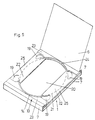
Der in Fig. 23 gezeigte Träger einer Verpackung weist
einen Grundkörper 31 aus Wellpappe 31a und eine
Zwischenlage 31b mit einer ebenen Oberfläche auf. Auf
diese Oberfläche sind zwei Kartonstücke aufgeklebt, die
die Auflagen 35 für die CD bereitstellen. Auf diese
Kartonstücke sind zwei Erhebungen 34a und 34b in Form
von weiteren Kartonstücken aufgeklebt, deren Dicke der
Dicke der CD entspricht. Die zwischen den Erhebungen
34a und 34b freie Fläche der Kartonstücke darunter bildet
die stufenförmige Auflage 35 für die CD. Die Oberfläche
33 der Zwischenlage 31b ist gegenüber der Auflage
35 abgesenkt (Fig. 23 und 25), sodaß die CD nur
außerhalb des Datenbereiches D aufliegt. The carrier of a packaging shown in FIG. 23 has
a
Die Erhebungen 34a und 34b sind in ihrer Form an den
Umfangsrand der Speicherplatte (CD) angepaßt und weisen
dazu in der Draufsicht kreisbogenförmige Anlageabschnitte
auf. Der Bogenradius dieser Anlageabschnitte
ist vorzugsweise geringfügig größer als oder im wesentlichen
gleich wie der Radius der einzulegenden Speicherplatte
36. Damit kann zwischen den als Zentriervorrichtungen
wirkenden Erhebungen 34a und 34b und der in
die Verpackung eingelegten Speicherplatte 36 (vgl. Fig.
24) ein geringfügiges Spiel vorhanden sein. Dies erleichtert
ein Einlegen und Herausnehmen der CD, da
diese im Gegensatz zu den bisher üblichen Kronenaufnehmern
nicht mehr kraftschlüssig festgeklemmt ist. Durch
die Ausbildung der Auflagefläche 35 aus Karton kann die
CD auch mit der an sich empfindlichen Unterseite ohne
Gefahr einer Beschädigung des Datenbereiches D lagesicher
aufliegen. Im Träger 31 sind in der Draufsicht
zwei gegenüberliegende Einbuchtungen bzw. Ausnehmungen
40 vorgesehen. Diese verlaufen, wie die Fig. 24 zeigt,
unter die Speicherplatte 36 hinein, sodaß der Rand der
Speicherplatte 36 mit zwei Fingern leichter erfaßbar
ist und damit die Speicherplatte 36 einfach vom Träger
31 abgehoben werden kann.The
Auf den rechteckigen Grundkörper 31 werden die beiden
Kartonstücke mit den Auflagen 35 und dann die beiden
Kartonstücke 34a und 34b aufgeklebt. Da ihr Außenrand
an drei Seiten mit dem Grundkörper übereinstimmt, ist
eine einfache Ausrichtung der aufgeklebten Teile am
Grundkörper 31 möglich, sodaß eine rasche maschinelle
Herstellung sichergestellt ist. Die Zwischenlage 31b
kann bei entsprechender Ausbildung der Oberseite der
Lage 31a aus Wellpappe sogar entfallen. Die Wellpappe
31a erlaubt es, bei geringem Gewicht eine hohe Steifigkeit
zu erzielen. Auch die Teile 31b, 34a und 34b können
aus Wellpappe (geringerer Dicke) hergestellt sein. The two are on the
Die offenen Seiten der Wellpappe können im Bedarfsfall durch eine nicht näher dargestellte Abdeckung abgedeckt sein.The open sides of the corrugated cardboard can be used if necessary covered by a cover, not shown his.
Nachdem die CD 36, wie in Fig. 24 oder 25 gezeigt, auf
die Auflagefläche 33 zwischen die Erhebungen 34a und
34b eingelegt worden ist, kann diese Einheit in eine
Hülle oder Schachtel aus Karton eingeschoben werden.
Ein Ausführungsbeispiel einer Hülle aus Karton ist in
Fig. 22 dargestellt.After the
Die Fig. 26 zeigt die Herstellung eines weiteren besonders
einfachen und exakt herstellbaren Ausführungsbeispiels.
Auf einem Grundträger 31 ist eine durchgehende
Kartonlage 32 aufgeklebt. Auf der Kartonlage 32 sind
die Erhebungen 34a, 34b, vorzugsweise ebenfalls aus
Karton, aufgeklebt. Um eine Auflage 35 zu erzielen, die
die Speicherplatte nur außerhalb ihres Datenbereichs D
unterstützt, wird mittels eines Stempels 41 einfach die
Kartonlage 32 in ihrem mittleren Bereich mit einer
kreisförmigen Einbuchtung versehen, sodaß im mittleren
Bereich eine abgesenkte Oberfläche 33 vorhanden ist und
vorhanden bleibt, nachdem der zylinderförmige Stempel
wieder entfernt worden ist. Die Absenkung der abgesenkten
Fläche 33 gegenüber der stufenförmigen Auflage 35
braucht nur gering sein. Es geht ja nur darum, daß der
Datenbereich D der Speicherplatte 36 nicht direkt auf
dem Karton der Verpackung aufliegt.Fig. 26 shows the manufacture of another particularly
simple and precisely producible embodiment.
On a
Alle Bauteile der erfindungsgemäßen Verpackung können auch aus Altpapier bzw. Altkarton hergestelltem Recyclingkarton gefertigt sein, womit die Umweltbelastung ingesamt noch weiter verringert wird.All components of the packaging according to the invention can also recycled cardboard made from waste paper or cardboard be made, with which the environmental impact overall is further reduced.
Claims (21)
- A process for the production of packaging for storage media, in particular optical storage disks or diskettes, characterised by the following steps:a) forming a bottom portion (11) from one or more glued cardboard layers (11a, 11b),b) forming a jacket portion (7) from cardboard,c) forming a holding and receiving portion (15) for the storage medium from cardboard,d) glueing the portions (7, 11, 15) formed in that way, wherein the holding and receiving portion (15) is arranged over the bottom portion (11) and the jacket portion (7) covers at least a part of the lateral edges of the holding and receiving portion (15) and/or the bottom portion (11).
- A process according to claim 1 characterised in that the jacket portion (7) extends under the bottom portion (11) and sections (9, 10) of the jacket portion (7), which project laterally beyond the bottom portion (7) are folded over upwardly and are glued fast, wherein the sections (9, 10) cover at least two oppositely disposed side edges of the bottom portion (11) and the holding and receiving portion (15) disposed thereabove.
- A process according to claim 1 or 2 characterised in that the bottom portion (11) is scored in a stamping out operation and then folded around the scored position (12') in order to form a two-layer bottom portion.
- A process according to claim 3 characterised in that the bottom portion is scored along two lines (12') which are parallel to the edge and the narrow sections which lie outside the scoring are turned in upwardly.
- A process according to one of claims 1 to 4 characterised in that a central opening (13) is stamped out of the bottom portion (11), preferably before it is folded.
- A process according to one of claims 1 to 5 characterised in that a depressed region (14) is embossed into the bottom portion (11).
- A process according to one of claims 1 to 6 characterised in that the jacket portion (7) is used with a bottom section (8) which corresponds in its dimensions to the bottom portion (11), wherein projecting from the bottom portion (11) are four flaps (6, 9, 10) which, preferably after fold grooves (12) have been impressed, are folded over upwardly and glued fast.
- A process according to one of claims 1 to 7 characterised in that a jacket portion (7) is used, from which there projects a flap which, after being folded over upwardly, forms an upwardly pivotable cover (6) which covers over the top side of the holding and receiving portion (15).
- A process according to one of claims 1 to 8 characterised in that a holding and receiving portion (15) having a central part and two lateral flaps (4) is used, which - preferably after an operation of impressing folding grooves (12) or scorings - are folded over upwardly on to the central part in order to hold in centred relationship a storage medium which is supported in the central region of the central part.
- A process according to one of claims 1 to 9 characterised in that a depressed region is embossed on the top side of the holding and receiving portion (15).
- A process according to one of claims 1 to 10 characterised in that a dispersion adhesive and/or a heat-activatable adhesive (hot melt) is used for the glueing operation.
- A process according to claim 11 characterised in that a heat-activatable adhesive (hot melt) which is applied in punctiform manner and a dispersion adhesive which is applied over an area are simultaneously used for the glueing operation.
- A packaging for storage media, in particular optical storage disks or diskettes, with a carrier (1) comprising at least one layer of cardboard with a depression for the insertion of the storage medium, wherein the carrier (1) can be preferably inserted into a cardboard case (18), which is open at both sides and wherein the carrier (1) for the storage media comprises a bottom portion (11) of one or more layers of cardboard and a holding portion (15) which is disposed above the bottom portion and which is provided with a depression and which also has one or more layers of cardboard, characterised in that the carrier also provides a jacket portion (7) which extends under the bottom portion (11) and which from there is folded over upwardly around the edges of the bottom portion (11) and at least partially of the holding portion (15) and glued.
- A packaging according to claim 13 characterised in that the jacket portion is turned in at two oppositely disposed edges between the bottom portion (11) and the holding portion (15) and covers two lateral edges of the bottom portion.
- A packaging according to claim 13 or 14 characterised in that the jacket portion (7) is folded over at two oppositely disposed sides of the carrier (1)over the bottom portion and the holding portion (15) disposed thereabove, and glued fast to the holding portion.
- A packaging according to one of claims 13 to 15 characterised in that the carrier (1) made of cardboard has a flap cover (6) with which the depression can be covered over at the top, wherein the flap cover (6) is preferably formed by a flap which is free at one side of the jacket portion (7).
- A packaging according to one of claims 13 to 16, in particular a compact disk, wherein the storage disk (36) contains optically readable data on a preferably annular data region of its underside, characterised in that the packaging has a support (35) for the storage disk (36), on which the underside of the storage disk (36) is supported with its radially outermost edge region outside the data region (D) while the data region (D) and the data-free region disposed radially within are arranged at a spacing from the packaging.
- A packaging according to one of claims 13 to 17 characterised in that it comprises a space in the carrier made of two or more layers of cardboard which is accessible from the side e.g. for taking up an enclosed booklet, wherein the space is also accessible from the top side of the carrier (1).
- A packaging for diskettes, in particular 3 ½ inch diskettes, characterised by a carrier (1) made of cardboard with a rectangular depression (2) into which at least one diskette can be laid.
- A packaging according to claim 19 characterised in that the carrier (1) has a flap cover (6) which also comprises cardboard and which covers over the depression (2) at the top and which is mounted pivotably on the remainder of the carrier (1).
- A packaging according to claim 19 or 20 characterised in that the carrier (1) has a plurality of superposed, at least partially glued layers of cardboard, wherein at least the uppermost layer has a through opening whose inside edge, which is adapted to the form of the disk, laterally delimits the depression (2), and that a subjacent layer is of a substantially continuous configuration and forms the bottom of the depression (2).
Applications Claiming Priority (9)
| Application Number | Priority Date | Filing Date | Title |
|---|---|---|---|
| DE9405421U DE9405421U1 (en) | 1994-03-30 | 1994-03-30 | Packaging for a disc-shaped optical storage disc |
| DE9405421U | 1994-03-30 | ||
| AT17439/49 | 1994-09-13 | ||
| AT174249 | 1994-09-13 | ||
| AT174294 | 1994-09-13 | ||
| AT1743949 | 1994-09-13 | ||
| AT1742/49 | 1994-09-13 | ||
| AT174394A AT402173B (en) | 1994-09-13 | 1994-09-13 | Producing package esp. for optical storage disc or diskette - stamping base, sides and cover of package from cardboard blanks for assembly and adhesive bonding together |
| PCT/AT1995/000062 WO1995027286A1 (en) | 1994-03-30 | 1995-03-27 | Process for producing packages for storage media |
Publications (2)
| Publication Number | Publication Date |
|---|---|
| EP0701732A1 EP0701732A1 (en) | 1996-03-20 |
| EP0701732B1 true EP0701732B1 (en) | 2002-02-27 |
Family
ID=27147859
Family Applications (1)
| Application Number | Title | Priority Date | Filing Date |
|---|---|---|---|
| EP95912069A Expired - Lifetime EP0701732B1 (en) | 1994-03-30 | 1995-03-27 | Process for producing packages for storage media |
Country Status (5)
| Country | Link |
|---|---|
| US (1) | US5772018A (en) |
| EP (1) | EP0701732B1 (en) |
| AU (1) | AU1940395A (en) |
| DE (1) | DE59510074D1 (en) |
| WO (1) | WO1995027286A1 (en) |
Families Citing this family (18)
| Publication number | Priority date | Publication date | Assignee | Title |
|---|---|---|---|---|
| SE9601431L (en) * | 1996-04-15 | 1997-10-16 | Pascal Denize | Attachment for disc shaped objects |
| DE19780519D2 (en) * | 1996-06-05 | 1999-06-17 | Pawi Verpackungen Ag | Disk packaging |
| GB9701477D0 (en) * | 1997-01-24 | 1997-03-12 | Robinson Duncan B | Wallet for packaging of compact discs |
| US5950821A (en) * | 1997-09-18 | 1999-09-14 | Blair Industries, Incorporated | Compact disk storage case |
| WO1999046773A1 (en) * | 1998-03-10 | 1999-09-16 | Phonosound Musikproduktions Gmbh | Self-adhesive spindle-shaped button disk and the use thereof |
| USD423931S (en) * | 1998-08-26 | 2000-05-02 | Alan Davis | Combination side-by-side package of compressed fabric article and companion article |
| USD420240S (en) * | 1998-11-27 | 2000-02-08 | Kim Sorenson | DVD holder |
| USD430445S (en) * | 1999-12-02 | 2000-09-05 | Pozzoli S.P.A. | Case for a compact disc |
| CH691679A5 (en) * | 2000-06-14 | 2001-09-14 | Al Askari Raad | Packaging cassette for use with compact discs and digital video discs of various shapes |
| JP2003026272A (en) * | 2001-07-09 | 2003-01-29 | Shintaro So | Paper board tray for compact disk(cd) |
| JP2004079014A (en) * | 2002-08-09 | 2004-03-11 | Toshiba Corp | Disk cartridge |
| US7108129B2 (en) * | 2003-10-10 | 2006-09-19 | Enxnet, Inc. | Optical disk storage case with blocking tongue |
| US7387203B2 (en) * | 2004-01-26 | 2008-06-17 | Time Warner, Inc. | Grooved board packaging and blank therefor |
| US20070006713A1 (en) * | 2005-07-08 | 2007-01-11 | Dunlop Manufacturing, Inc. | Guitar pick package |
| US7241255B2 (en) * | 2005-07-22 | 2007-07-10 | Kyoto Seisakusho Co., Ltd. | Method and apparatus for attaching a hook-and-loop fastener to a carton with a lid |
| US8132668B2 (en) * | 2009-01-07 | 2012-03-13 | The John Henry Company | Packaging for electrical components |
| USD753937S1 (en) * | 2013-10-24 | 2016-04-19 | Concord Music Group, Inc. | Case for recorded media |
| US9827741B2 (en) * | 2014-05-15 | 2017-11-28 | Multi Packaging Solutions, Inc. | Display device |
Family Cites Families (10)
| Publication number | Priority date | Publication date | Assignee | Title |
|---|---|---|---|---|
| DE2333124A1 (en) * | 1973-06-29 | 1975-05-15 | Dossmann Kg Friedr | METHOD OF MANUFACTURING A FOLDED CAP BOX FROM A TWO-PART CARDBOARD CUTOUT |
| EP0115746A3 (en) * | 1983-02-02 | 1984-09-26 | Interrondo AG | Method of manufacturing boxes and boxes made by this method |
| US4709812A (en) * | 1986-07-11 | 1987-12-01 | Agi Incorporated | Compact disc package and a method of making same |
| NL8702565A (en) * | 1987-10-28 | 1989-05-16 | Docdata Bv | Simple cardboard package for compact disc - is made from single blank folded to leave curved holding slot |
| US5188229A (en) * | 1991-04-05 | 1993-02-23 | International Paper Company | Compact disc package |
| DE4134634A1 (en) * | 1991-10-19 | 1993-04-22 | Guenther Abel | Packing material made from corrugated cardboard - has cardboard sheets which are placed one upon another and have holes cut by milling cutters |
| AT403569B (en) * | 1992-05-15 | 1998-03-25 | Walch Herbert | PACKING FOR A DISC-SHAPED OPTICAL DISK, IN PARTICULAR A COMPACT DISC |
| US5186327A (en) * | 1992-06-04 | 1993-02-16 | Mccafferty Daniel K | Compact disc retaining sheet |
| US5460265A (en) * | 1994-02-28 | 1995-10-24 | Chicago Packaging Corp. | Blank construction and package for a compact disc |
| US5518488A (en) * | 1995-03-20 | 1996-05-21 | Schluger; Allen | CD holder of cardboard and method of construction |
-
1994
- 1994-12-06 US US08/349,789 patent/US5772018A/en not_active Expired - Fee Related
-
1995
- 1995-03-27 WO PCT/AT1995/000062 patent/WO1995027286A1/en active IP Right Grant
- 1995-03-27 AU AU19403/95A patent/AU1940395A/en not_active Abandoned
- 1995-03-27 EP EP95912069A patent/EP0701732B1/en not_active Expired - Lifetime
- 1995-03-27 DE DE59510074T patent/DE59510074D1/en not_active Expired - Fee Related
Also Published As
| Publication number | Publication date |
|---|---|
| DE59510074D1 (en) | 2002-04-04 |
| WO1995027286A1 (en) | 1995-10-12 |
| EP0701732A1 (en) | 1996-03-20 |
| AU1940395A (en) | 1995-10-23 |
| US5772018A (en) | 1998-06-30 |
Similar Documents
| Publication | Publication Date | Title |
|---|---|---|
| EP0701732B1 (en) | Process for producing packages for storage media | |
| EP0086484B1 (en) | Storage box for disc-shaped information carriers with a high recording density | |
| DE3148443C2 (en) | Folding box with viewing window | |
| DE4321608C2 (en) | Plastic housing and method for its production | |
| DE602004010926T2 (en) | GIFT box container | |
| WO1994022742A1 (en) | Compact disk package made from a foldable flat material blank | |
| EP0260345A2 (en) | Packaging unit with several cardboard boxes | |
| DE1797428B1 (en) | Record cover | |
| EP1089922B1 (en) | Sales packaging | |
| EP0335826A2 (en) | Protective covering for a discoid record carrier | |
| DE19500743A1 (en) | Package carrier for semiconductor components | |
| EP0203889A1 (en) | Packaging carton for film cartridges | |
| DE3703251A1 (en) | TRAY-SHAPED BOX | |
| DE2844444C2 (en) | Packaging, in particular cuboid cigarette packs, and processes for producing blanks for this packaging | |
| EP0374663B1 (en) | Packaging container | |
| DE69726420T2 (en) | METHOD FOR PRODUCING A PACKAGING WITH A CLIP-ON LID FROM A CUT | |
| EP0503171A1 (en) | Protecting cover for a discoid record carrier | |
| EP1195329A2 (en) | Folding box with an offset internal bottom | |
| EP0932903A1 (en) | Embossed sound track | |
| EP0337181A1 (en) | Compact disc package | |
| AT402173B (en) | Producing package esp. for optical storage disc or diskette - stamping base, sides and cover of package from cardboard blanks for assembly and adhesive bonding together | |
| EP3284685B1 (en) | Applicator for handling of rim protection films | |
| DE3233670C2 (en) | Method of making a container | |
| EP0799481B1 (en) | Method and device for accommodating disc-shaped information carriers | |
| DE4320191A1 (en) | CD sleeve |
Legal Events
| Date | Code | Title | Description |
|---|---|---|---|
| PUAI | Public reference made under article 153(3) epc to a published international application that has entered the european phase |
Free format text: ORIGINAL CODE: 0009012 |
|
| 17P | Request for examination filed |
Effective date: 19951222 |
|
| AK | Designated contracting states |
Kind code of ref document: A1 Designated state(s): BE CH DE DK ES FR GB IE IT LI LU NL SE |
|
| 17Q | First examination report despatched |
Effective date: 19981223 |
|
| GRAG | Despatch of communication of intention to grant |
Free format text: ORIGINAL CODE: EPIDOS AGRA |
|
| GRAG | Despatch of communication of intention to grant |
Free format text: ORIGINAL CODE: EPIDOS AGRA |
|
| GRAH | Despatch of communication of intention to grant a patent |
Free format text: ORIGINAL CODE: EPIDOS IGRA |
|
| GRAH | Despatch of communication of intention to grant a patent |
Free format text: ORIGINAL CODE: EPIDOS IGRA |
|
| REG | Reference to a national code |
Ref country code: GB Ref legal event code: IF02 |
|
| GRAA | (expected) grant |
Free format text: ORIGINAL CODE: 0009210 |
|
| AK | Designated contracting states |
Kind code of ref document: B1 Designated state(s): BE CH DE DK ES FR GB IE IT LI LU NL SE |
|
| PG25 | Lapsed in a contracting state [announced via postgrant information from national office to epo] |
Ref country code: NL Free format text: LAPSE BECAUSE OF FAILURE TO SUBMIT A TRANSLATION OF THE DESCRIPTION OR TO PAY THE FEE WITHIN THE PRESCRIBED TIME-LIMIT Effective date: 20020227 Ref country code: IT Free format text: LAPSE BECAUSE OF FAILURE TO SUBMIT A TRANSLATION OF THE DESCRIPTION OR TO PAY THE FEE WITHIN THE PRE;WARNING: LAPSES OF ITALIAN PATENTS WITH EFFECTIVE DATE BEFORE 2007 MAY HAVE OCCURRED AT ANY TIME BEFORE 2007. THE CORRECT EFFECTIVE DATE MAY BE DIFFERENT FROM THE ONE RECORDED.SCRIBED TIME-LIMIT Effective date: 20020227 Ref country code: IE Free format text: LAPSE BECAUSE OF FAILURE TO SUBMIT A TRANSLATION OF THE DESCRIPTION OR TO PAY THE FEE WITHIN THE PRESCRIBED TIME-LIMIT Effective date: 20020227 Ref country code: GB Free format text: LAPSE BECAUSE OF FAILURE TO SUBMIT A TRANSLATION OF THE DESCRIPTION OR TO PAY THE FEE WITHIN THE PRESCRIBED TIME-LIMIT Effective date: 20020227 Ref country code: FR Free format text: LAPSE BECAUSE OF FAILURE TO SUBMIT A TRANSLATION OF THE DESCRIPTION OR TO PAY THE FEE WITHIN THE PRESCRIBED TIME-LIMIT Effective date: 20020227 |
|
| REG | Reference to a national code |
Ref country code: CH Ref legal event code: EP |
|
| PG25 | Lapsed in a contracting state [announced via postgrant information from national office to epo] |
Ref country code: LU Free format text: LAPSE BECAUSE OF NON-PAYMENT OF DUE FEES Effective date: 20020327 |
|
| PG25 | Lapsed in a contracting state [announced via postgrant information from national office to epo] |
Ref country code: LI Free format text: LAPSE BECAUSE OF NON-PAYMENT OF DUE FEES Effective date: 20020331 Ref country code: CH Free format text: LAPSE BECAUSE OF NON-PAYMENT OF DUE FEES Effective date: 20020331 Ref country code: BE Free format text: LAPSE BECAUSE OF NON-PAYMENT OF DUE FEES Effective date: 20020331 |
|
| REF | Corresponds to: |
Ref document number: 59510074 Country of ref document: DE Date of ref document: 20020404 |
|
| PG25 | Lapsed in a contracting state [announced via postgrant information from national office to epo] |
Ref country code: SE Free format text: LAPSE BECAUSE OF FAILURE TO SUBMIT A TRANSLATION OF THE DESCRIPTION OR TO PAY THE FEE WITHIN THE PRESCRIBED TIME-LIMIT Effective date: 20020527 Ref country code: DK Free format text: LAPSE BECAUSE OF FAILURE TO SUBMIT A TRANSLATION OF THE DESCRIPTION OR TO PAY THE FEE WITHIN THE PRESCRIBED TIME-LIMIT Effective date: 20020527 |
|
| NLV1 | Nl: lapsed or annulled due to failure to fulfill the requirements of art. 29p and 29m of the patents act | ||
| GBV | Gb: ep patent (uk) treated as always having been void in accordance with gb section 77(7)/1977 [no translation filed] |
Effective date: 20020227 |
|
| PG25 | Lapsed in a contracting state [announced via postgrant information from national office to epo] |
Ref country code: ES Free format text: LAPSE BECAUSE OF FAILURE TO SUBMIT A TRANSLATION OF THE DESCRIPTION OR TO PAY THE FEE WITHIN THE PRESCRIBED TIME-LIMIT Effective date: 20020829 |
|
| BERE | Be: lapsed |
Owner name: *WALCH HERBERT Effective date: 20020331 |
|
| PGFP | Annual fee paid to national office [announced via postgrant information from national office to epo] |
Ref country code: DE Payment date: 20020930 Year of fee payment: 8 |
|
| REG | Reference to a national code |
Ref country code: IE Ref legal event code: FD4D |
|
| REG | Reference to a national code |
Ref country code: CH Ref legal event code: PL |
|
| EN | Fr: translation not filed | ||
| PLBE | No opposition filed within time limit |
Free format text: ORIGINAL CODE: 0009261 |
|
| STAA | Information on the status of an ep patent application or granted ep patent |
Free format text: STATUS: NO OPPOSITION FILED WITHIN TIME LIMIT |
|
| 26N | No opposition filed |
Effective date: 20021128 |
|
| PG25 | Lapsed in a contracting state [announced via postgrant information from national office to epo] |
Ref country code: DE Free format text: LAPSE BECAUSE OF NON-PAYMENT OF DUE FEES Effective date: 20031001 |
|
| REG | Reference to a national code |
Ref country code: CH Ref legal event code: PK Free format text: DIE PRIORITAETSAKTENZEICHEN WURDEN BERICHTIGT: |