EP0701418B1 - Dispositif de separation aux ultrasons de plaques sclerotiques et appareil de traitement comprenant ce dispositif - Google Patents
Dispositif de separation aux ultrasons de plaques sclerotiques et appareil de traitement comprenant ce dispositif Download PDFInfo
- Publication number
- EP0701418B1 EP0701418B1 EP94918811A EP94918811A EP0701418B1 EP 0701418 B1 EP0701418 B1 EP 0701418B1 EP 94918811 A EP94918811 A EP 94918811A EP 94918811 A EP94918811 A EP 94918811A EP 0701418 B1 EP0701418 B1 EP 0701418B1
- Authority
- EP
- European Patent Office
- Prior art keywords
- liquid
- working part
- probe
- transmission part
- handle
- Prior art date
- Legal status (The legal status is an assumption and is not a legal conclusion. Google has not performed a legal analysis and makes no representation as to the accuracy of the status listed.)
- Expired - Lifetime
Links
- 238000002604 ultrasonography Methods 0.000 title claims abstract description 21
- 230000002784 sclerotic effect Effects 0.000 title description 4
- 239000000523 sample Substances 0.000 claims abstract description 62
- 239000007788 liquid Substances 0.000 claims abstract description 44
- 230000005540 biological transmission Effects 0.000 claims abstract description 34
- 239000000463 material Substances 0.000 claims abstract description 7
- 238000009736 wetting Methods 0.000 claims abstract description 6
- 210000001367 artery Anatomy 0.000 claims description 41
- 210000002808 connective tissue Anatomy 0.000 claims description 16
- 230000007704 transition Effects 0.000 claims description 6
- 239000004033 plastic Substances 0.000 claims description 5
- 238000003780 insertion Methods 0.000 claims description 4
- 230000037431 insertion Effects 0.000 claims description 4
- 229920001343 polytetrafluoroethylene Polymers 0.000 claims description 4
- 239000004810 polytetrafluoroethylene Substances 0.000 claims description 4
- 208000037260 Atherosclerotic Plaque Diseases 0.000 abstract description 2
- 238000013171 endarterectomy Methods 0.000 description 9
- 238000000034 method Methods 0.000 description 8
- 238000013461 design Methods 0.000 description 5
- 210000001519 tissue Anatomy 0.000 description 5
- 230000000472 traumatic effect Effects 0.000 description 5
- 230000002792 vascular Effects 0.000 description 4
- 206010050902 Postoperative thrombosis Diseases 0.000 description 3
- 208000031481 Pathologic Constriction Diseases 0.000 description 2
- 208000007536 Thrombosis Diseases 0.000 description 2
- 230000015572 biosynthetic process Effects 0.000 description 2
- 206010020718 hyperplasia Diseases 0.000 description 2
- 230000001788 irregular Effects 0.000 description 2
- 238000000926 separation method Methods 0.000 description 2
- 238000012546 transfer Methods 0.000 description 2
- 230000003144 traumatizing effect Effects 0.000 description 2
- 206010003210 Arteriosclerosis Diseases 0.000 description 1
- 206010003211 Arteriosclerosis coronary artery Diseases 0.000 description 1
- 201000001320 Atherosclerosis Diseases 0.000 description 1
- 229910000831 Steel Inorganic materials 0.000 description 1
- 208000027418 Wounds and injury Diseases 0.000 description 1
- 230000001464 adherent effect Effects 0.000 description 1
- 238000002399 angioplasty Methods 0.000 description 1
- 230000000181 anti-adherent effect Effects 0.000 description 1
- 208000011775 arteriosclerosis disease Diseases 0.000 description 1
- 230000017531 blood circulation Effects 0.000 description 1
- 230000006378 damage Effects 0.000 description 1
- 238000013016 damping Methods 0.000 description 1
- 230000006735 deficit Effects 0.000 description 1
- 230000001419 dependent effect Effects 0.000 description 1
- 238000011161 development Methods 0.000 description 1
- 230000018109 developmental process Effects 0.000 description 1
- 210000001105 femoral artery Anatomy 0.000 description 1
- 208000014674 injury Diseases 0.000 description 1
- 230000007794 irritation Effects 0.000 description 1
- 210000001087 myotubule Anatomy 0.000 description 1
- 230000002093 peripheral effect Effects 0.000 description 1
- 230000002572 peristaltic effect Effects 0.000 description 1
- -1 polytetrafluoroethylene Polymers 0.000 description 1
- 230000002980 postoperative effect Effects 0.000 description 1
- 238000002601 radiography Methods 0.000 description 1
- 239000007779 soft material Substances 0.000 description 1
- 239000010959 steel Substances 0.000 description 1
- 230000036262 stenosis Effects 0.000 description 1
- 208000037804 stenosis Diseases 0.000 description 1
- 238000012549 training Methods 0.000 description 1
Images


Classifications
-
- A—HUMAN NECESSITIES
- A61—MEDICAL OR VETERINARY SCIENCE; HYGIENE
- A61B—DIAGNOSIS; SURGERY; IDENTIFICATION
- A61B17/00—Surgical instruments, devices or methods
- A61B17/22—Implements for squeezing-off ulcers or the like on inner organs of the body; Implements for scraping-out cavities of body organs, e.g. bones; for invasive removal or destruction of calculus using mechanical vibrations; for removing obstructions in blood vessels, not otherwise provided for
- A61B17/22004—Implements for squeezing-off ulcers or the like on inner organs of the body; Implements for scraping-out cavities of body organs, e.g. bones; for invasive removal or destruction of calculus using mechanical vibrations; for removing obstructions in blood vessels, not otherwise provided for using mechanical vibrations, e.g. ultrasonic shock waves
- A61B17/22012—Implements for squeezing-off ulcers or the like on inner organs of the body; Implements for scraping-out cavities of body organs, e.g. bones; for invasive removal or destruction of calculus using mechanical vibrations; for removing obstructions in blood vessels, not otherwise provided for using mechanical vibrations, e.g. ultrasonic shock waves in direct contact with, or very close to, the obstruction or concrement
-
- A—HUMAN NECESSITIES
- A61—MEDICAL OR VETERINARY SCIENCE; HYGIENE
- A61B—DIAGNOSIS; SURGERY; IDENTIFICATION
- A61B17/00—Surgical instruments, devices or methods
- A61B2017/00831—Material properties
- A61B2017/0084—Material properties low friction
- A61B2017/00849—Material properties low friction with respect to tissue, e.g. hollow organs
-
- A—HUMAN NECESSITIES
- A61—MEDICAL OR VETERINARY SCIENCE; HYGIENE
- A61B—DIAGNOSIS; SURGERY; IDENTIFICATION
- A61B17/00—Surgical instruments, devices or methods
- A61B17/32—Surgical cutting instruments
- A61B17/3205—Excision instruments
- A61B17/3207—Atherectomy devices working by cutting or abrading; Similar devices specially adapted for non-vascular obstructions
- A61B2017/320741—Atherectomy devices working by cutting or abrading; Similar devices specially adapted for non-vascular obstructions for stripping the intima or the internal plaque from a blood vessel, e.g. for endarterectomy
Definitions
- the invention relates to a device for detaching sclerotic plaques according to the preamble of claim 1, as is known for example from AT-B-340572, and a treatment set containing such a device according to the preamble of claim 8.
- occluded arteries are expanded using a balloon catheter.
- This treatment which is often carried out as a preparatory or additional measure for vascular plastic, always works in one traumatic to some extent. Secondary stenoses due to miointimal hyperplasia are the result.
- US Pat. No. 4,962,755 describes a method in which a short, curved ultrasound probe is inserted into an incision in the artery. Liquid is fed to the vibrating working part of the probe via a rigid tube arranged parallel to the probe. Since on the one hand the vibrating working part comes to rest between detached plaque or media and adventitia and on the other hand the liquid tube is not pushed in when pushed further into the artery, wetting of the vibrating working part is only possible on one side and only to a limited extent. After loosening of the plaque, the distance is removed from an incision made in the middle of the occlusion or from two distal or proximal incisions the plaques using forceps are necessary.
- AT-PS-340 572 describes ultrasound probes which are intended for the removal of both small-area and extensive plaques.
- the liquid as one of two alternative possibilities described, is passed through a channel provided inside the probe through outlet openings provided at the transition point to the inclined part fed to the vibrating working part.
- the working part vibrates transversely, the liquid will not be able to reach the tip of the working part, but will be sprayed off beforehand.
- the long probe which is designed in the form of a ring stripper, the liquid - again as one of two alternative possibilities - is fed to the transversely vibrating ring via a channel provided in the probe.
- the object of the invention is to provide a device which enables the detachment of sclerotic plaques and the media, regardless of the degree of aterosclerotic impairment thereof, with - apart from a small incision - closed artery, with traumatic effects on the remaining vessel wall can be avoided.
- the angled arrangement of the working part of the probe with respect to the longitudinal axis of the transmission part - the specific design of the working part depending on the treatment required, such as the type and lumen of the artery and the extent of the plaque - simplifies access to the interior of the artery.
- a spatula-shaped working part is ideal for removing small-area plaques, which can be done from two incisions in the artery, which are made distally and proximally.
- a working part designed in this way is also used to prepare the distal end point, in which the media is detached from the adventitia, after which a differently designed probe can be inserted through the small incision in the artery.
- Such a probe, the working part of which is in the form of a ring, but the transmission part is designed as a long, thin rod - in the manner of the ring stripper known from the classic, semi-open endarterectomy - has proven to be suitable for removing extensive obliterations, for example in the arteria femoralis, advantageous.
- the probe according to the invention is distinguished by the fact that it - exposure to the relatively low frequencies around 30 kHz - exposes the occlusion area along the entire length of the artery with gentle, i.e. non-traumatizing, and thereby complete detachment of the media from the adventitia, since even when the probe is pushed far into the artery, the ring-shaped working part vibrates with essentially unchanged energy and frequency and at the same time is evenly wetted with liquid over its ring surface.
- the transmission part of such a probe is preferably designed as a thin steel rod with a diameter of approximately 1 mm and a length of up to 60 cm and more, so that it can be guided without resistance even with slightly curved arterial courses.
- the liquid-carrying tube which surrounds the transmission part is preferably formed from a dimensionally stable plastic which is flexible over its longitudinal extent, for which polytetrafluoroethylene (PTFE) in particular is suitable on account of its excellent, anti-adhesive properties. This achieves both an improved sliding ability of the probe in the space between detached media and adventitia, as well as an inert behavior towards vibrations that may be transmitted via the liquid.
- PTFE polytetrafluoroethylene
- the ring-shaped working part of the ring probe is wetted with liquid over its entire ring surface, the liquid is applied through an ring-shaped opening, which is possibly given by the diameter of the tube itself. Since the liquid emerges from this opening with pressure, it becomes between the attachment point on both sides Ring and transmission part distributed on the vibrating ring.
- the probe with the spatula-shaped working part hereinafter referred to as the spatula probe, can - in relation to the transfer part and the tube for supplying the liquid - be designed in principle in accordance with the ring probe.
- this probe is generally used to treat an area immediately adjacent to the incision in the artery, with only its working part being inserted into the artery, less attention needs to be paid to the question of the lubricity of the tube material and the rigidity and flexibility thereof.
- a material such as PVC, which is easier and cheaper to process, while maintaining similarly advantageous properties in terms of avoiding energy losses.
- the design of the working part in the form of a spatula is preferred, since this simplifies the guidance between detached media and adventitia, but other configurations are also conceivable, for example rod-shaped or lenticular heads.
- the tube carrying the liquid can completely enclose the spatula-shaped working part in the region of the transition to the transfer part, which will be particularly useful if it is made of relatively soft material.
- at least two openings should be provided for the outlet of the liquid, which are arranged on both sides of the spatula, so that the liquid emerging with a certain pressure is distributed over the entire surface of the working part.
- several openings can be provided, at least symmetrically around the circumference of the working part of any design.
- a treatment set that enables the rapid, treatment-specific change of treatment probes during a treatment, will advantageously simplify and optimize the course of treatment.
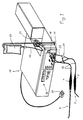
- FIG. 1 shows an ultrasound generator 17 with two connections 18, 19, to which two devices according to the invention for detaching aterosclerotic plaques are connected via lines 23.
- the two devices carry on their respective handles 1 probes 7 and 8 of different designs, as can be seen better in FIGS. 2 and 3 and 3a and whose specific use is described with reference to FIGS. 4a to 4l.
- Piezoelectric ultrasonic transmitters are provided in the handles 1 and are excited with the corresponding frequency and power via the output signals of the generator.
- Sterile liquid is removed from a liquid container 20 by means of a peristaltic pump 21 and via a liquid line 22 to liquid channels 2 provided in the respective handles 1 of the two devices (Fig. 2 or 3) passed.
- a T-tap 24 is provided to deliver the liquid to the probe currently in use.
- Liquid supply lines and lines 23 are routed together in some areas.
- the devices to be used can be selected via a pedal switch 25 and the supply of the liquid can be started when the pump 21 is activated. All necessary data, such as the selected device, ultrasound frequency or duration of the treatment, are shown on a display 26.
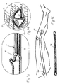
- FIG. 2 shows the probe 8, which is suitable for insertion into an incision made in an artery.
- a probe 8 is referred to below as a ring probe, since a so-called working part 4 designed as a ring is articulated on a long, rod-shaped transmission part 6 with a slight kink against the longitudinal axis 13 of the transmission part 6.
- the transmission part 6 is fastened to the handle 1 comprising the ultrasound transmitter, in the interior of which the channel 2 is provided for the sterile liquid which is pressed therefrom out of an opening 27 into the interior of a space which is passed through a tube enveloping the transmission part 6 10 is limited.
- the channel 2a carrying the liquid can alternatively also be arranged such that it is designed in the form of a branch line to the ultrasound transmitter 60 on the handle.
- the liquid supplied via the liquid line 23 is fed via the bypass channel 2a to the tube 10 surrounding the transmission part 6. This configuration can additionally prevent possible damping of the ultrasound energy available via the ultrasound transmitter 60.
- the tube 10 is made of a rigid plastic, but flexible in the longitudinal direction of the probe 8, preferably PTFE, which, in addition to these properties, has particularly good sliding properties. This becomes clear from the mode of operation described in FIGS. 4 a to 4 l.
- the tube 10 is open at its end facing the working part 4, so that the liquid, which is pressed into the channel 2 by the pump 21 (FIG. 1), emerges from this circular opening 15 with a certain pressure, and thus the annular working part on all sides wetted.
- Working part 4 carries out essentially transverse vibrations, cavitation cavities form in the liquid, pressures of 2 to 3 atm are released when these cavities collapse and act on the surrounding material.
- Such ring probes 8 will have different sized ring diameters depending on the inner artery diameter.
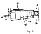
- FIG. 3 and 3a show a short probe 7 which is suitable for removing small-area plaques and in particular for preparing the so-called "end point” or the "proximal point".
- the working part 3 of this probe 7 is spatula-shaped, an area of the transmission part 6 is bent relative to the axis 14 determined by the common axis of the handle 1 and the transmission part adjoining it.
- the transmission part 5 is completely encased by a liquid-carrying tube 9.
- the liquid is pressed via the pump 21 (FIG. 1) via the channel 2 in the handle 1 out of the opening 27 into the space between the tube 9 and the transmission part 5.
- the spatula-shaped working part 3 protrudes freely from the tube 9, which lies firmly against the probe 7 in this area of the transition between the working part 3 and the transmission part 5.
- Two openings 16 (detail A of Fig.3a) are provided on both sides of the spatula-shaped working part 3 through which the liquid under pressure on the Working part 3 is pressed, so that - even with a vibrating working part - the liquid in the area of the opening (s) cannot be immediately sprayed off (as is the case with AT-A-340 572, for example), the working part is evenly wetted on all sides .
- the transmission part can be straight, for example the working part can be shaped like a rod or lens head.
- the type and number of openings for the liquid to exit the tube will then also have to be selected. It is essential that the openings are arranged essentially symmetrically around the circumference of the working part.
- the tube in the so-called spatula probe 7, which is generally not inserted into the interior of an artery, or only with its working part 3 - as can be seen from FIGS. 4 a to 4 l - is made of plastic, PVC, for example, due to offers its advantageous properties, as already introduced in the introduction.
- the device according to the invention can be used for disobliterations in the most varied of vessels, be it in the case of coronary sclerosis or the arteriosclerosis of the subclavian initial part.
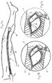
- the use of the device according to the invention is described in FIGS. 4 a to 4 l on the basis of the disobliteration of a peripheral vessel, namely the arteria femoralis 31, which may have elongated aterosclerotic obliterations.
- the method for detaching sclerotic plaques by means of the device according to the invention proves to be particularly successful since the treatment can be carried out with the artery closed and traumatic effects on the remaining vascular wall can be avoided.
- the artery 31 in the area of the so-called "end point" 32 is exposed and an incision 12 is made.
- This incision 12 is about 1 to 1.5 cm long.
- the preparation of the "end point" 32 must be carried out so that the transition between the treated and untreated inner wall of the artery is smooth, i.e. without protruding scraps of tissue or edges.
- the incision 12 lies in the area of the "end point" 32 and thus at a point where there are no longer any obliterations.
- the vibrating spatula probe 7 is guided to the vessel wall (Fig. 4b), due to the cavitation pressure of approx. 2 to 3 atm on the tissue, the media 29 detaches from the adventitia 30, since the connection between these two layers of artery wall is relatively weak ( Fig.4c).
- This relatively weak connection between the non-plaque media and the adventitia was one of the reasons for the sometimes roughly irregular surfaces of the remaining artery inner wall when preparing the "end point" in the known methods.
- the round tip of the spatula probe 7 is introduced into this small transverse incision 34 (FIG. 4e) and is guided transversely around the inner wall of the artery (FIG. 4f, 4g). Due to the cavitational pressure there is a regular and smooth separation of the circular muscle fibers lying against the inner wall of the vessel and the intima take place without a cut being made. In this way, the preparation of the "end-point" is achieved without any other treatment steps, such as the application of sutures inside the artery. 4g shows the smooth separation between the media layer 29 detached from the adventitia 30 and the media layer 29a adhering to the adventitia 30.
- the second phase of treatment relates to the total disobstruction of the cylinder occluding the artery.
- the ring probe 8 is inserted into the incision 12 so that the vibrating, ring-shaped working part 4 is located between detached media 29 and adventitia 30 (FIG. 4h).
- the diameter of the ring 4 of the ring probe 8 will be selected depending on the lumen of the artery.
- the media 29 and thus also the obstructing plaque 28 detaches from the adventitia 30 without there being a traumatizing effect on the vessel wall.
- the tube 10 enveloping the vibrating transmission part 6 is made of a material with a high sliding coefficient, further advancement takes place within the artery 11 unhindered, the vibrability of the transmission part 6 is not reduced or even canceled as a result of wall pressure thereon (FIG. 4i).
- This second treatment step in which the ring probe 8 is gently pushed forward and possibly also pushed back, according to the arrows 35 in FIG. 4i, ends at the "proximal point" 36, i.e. at a point on the artery that is again free of occluding plaques 28 (FIG. 4j).
- This "proximal point" 36 is then prepared in a last treatment step in a manner corresponding to that of the "end point” 32.
- an incision 12 a is made in the longitudinal direction of the artery 11, by means of the spatula probe 7 first causing a small-area detachment of the media 29, in the manner described with reference to FIG. 4 d, a small transverse incision is made in the detached media 29 and then the vibrating spatula probe 7 is inserted and the media 29 is detached from the adventitia 30 by rotating it (FIG. 4k).
- the dividing line between detached and remaining media is clean and smooth, the risk of developing postoperative thrombosis is minimized.
- the entire occlusion cylinder 37 can be pulled out through one of the two incisions 12 or 12a at the "end point” or at the "proximal point", the incisions 12 and 12a are sutured and the blood flow in the disostruced arterial area is reactivated (FIG. 41). .
- the remaining inner wall of the disostructured artery is free of irregularities because all of the media in this area has been removed regardless of the degree of atherosclerosis.
Landscapes
- Health & Medical Sciences (AREA)
- Surgery (AREA)
- Engineering & Computer Science (AREA)
- Life Sciences & Earth Sciences (AREA)
- Medical Informatics (AREA)
- Molecular Biology (AREA)
- Vascular Medicine (AREA)
- Orthopedic Medicine & Surgery (AREA)
- Biomedical Technology (AREA)
- Heart & Thoracic Surgery (AREA)
- Mechanical Engineering (AREA)
- Nuclear Medicine, Radiotherapy & Molecular Imaging (AREA)
- Animal Behavior & Ethology (AREA)
- General Health & Medical Sciences (AREA)
- Public Health (AREA)
- Veterinary Medicine (AREA)
- Surgical Instruments (AREA)
- Ultra Sonic Daignosis Equipment (AREA)
- Measuring And Recording Apparatus For Diagnosis (AREA)
- Dental Tools And Instruments Or Auxiliary Dental Instruments (AREA)
Claims (8)
- Dispositif de séparation de plaques artérioscléreuses (28) par utilisation de vibrations ultrasonores, par le décollement des médias (29) de l'adventitia (30), avec un transmetteur d'ultrasons (60) pouvant être raccordé à un générateur d'ultrasons (17), une sonde (7; 8) fixée à une poignée (1) et présentant une partie de travail (3; 4) et une partie de transmission (5; 6), la partie de travail étant articulée sur la partie de transmission, de manière que la partie de travail fasse avec l'axe longitudinal (13) de la partie de transmission (6) par rapport à sa zone, raccordée directement à la poignée (1), un angle plus grand que zéro, et pourvue d'un tubule (9; 10) guidant du liquide, liquide servant à mouiller la partie de travail (3; 4) de la sonde (7; 8), un canal (2; 2a) étant prévu dans, respectivement sur la poignée (1) pour assurer l'amenée du liquide dans le tubule (9; 10), caractérisé en ce que le tubule (9; 10) est constitué d'un matériau dont le coefficient de frottement par rapport au liquide est négligeable, en ce que le tubule enveloppe complètement la partie de transmission (5; 6) et en ce que des moyens (15; 16) destinés à mouiller en liquide la totalité de la surface de la partie de travail (3; 4) sont prévus.
- Dispositif selon la revendication 1, en particulier pour l'insertion dans une entaille (12) ménagée dans une artère (11), caractérisé en ce que la partie de travail (4) est réalisée sous la forme d'un anneau, articulé sur un côté à la partie de transmission (6), et en ce que la surface de l'anneau fait, avec l'axe longitudinal (13) de la partie de transmission (6), un angle supérieur à zéro.
- Dispositif de séparation de plaques artérioscléreuses, en particulier dans la zone proximale d'une entaille (12), ménagée dans une artère (11), selon la revendication 1, caractérisé en ce que la partie de travail (3) est réalisée en forme de barre - en particulier sous la forme d'une spatule et fait avec l'axe longitudinal (14) de la partie de transmission (5) - par rapport à sa zone se raccordant directement à la poignée (1) - un angle supérieur à zéro.
- Dispositif selon l'une des revendications précédentes, caractérisé en ce que le tubule (9; 10) est fixé, à une extrémité, sur la poignée et, à l'autre extrémité, est prévue au moins une ouverture (15; 16), telle que le liquide destiné au mouillage de toutes les phases de la partie de travail (3; 4) puisse être distribué.
- Dispositif selon la revendication 4, caractérisé en ce que le tubule (9) entoure, sur son extrémité opposée à la poignée (1), la partie de travail (3) dans la zone de la transition vers la partie de transmission (5), au moins deux ouvertures (16) étant prévues, symétriquement de part et d'autre de la partie de travail (3).
- Dispositif selon l'une des revendications précédentes, caractérisé en ce que la partie de transmission (6) et le tubule (10) sont flexibles.
- Dispositif selon l'une des revendications précédentes, caractérisé en ce que le tubule (9; 10) est réalisé en matière synthétique, en particulier en PVC ou en PTFE.
- Ensemble de traitement équipé d'un dispositif pour séparer des plaques artérioscléreuses, selon l'une des revendications précédentes, et avec un générateur à ultrasons (17), caractérisé en ce qu'au générateur à ultrasons (17) sont associées les parties ci-après:- au moins deux raccordements (18; 19), destinés chacun à au moins l'un des dispositifs selon la revendication 2 respectivement 3, en particulier dans le mode de réalisation selon l'une des revendications 4 à 7;- au moins un transformateur d'amplitude associé aux raccordements (18; 19);- au moins un récipient (20) pour le liquide, équipé d'une conduite d'amenée (20), présentant au moins une pompe de transfert (21) et menant au canal (2) du dispositif respectif.
Priority Applications (1)
| Application Number | Priority Date | Filing Date | Title |
|---|---|---|---|
| EP94918811A EP0701418B1 (fr) | 1993-06-01 | 1994-05-28 | Dispositif de separation aux ultrasons de plaques sclerotiques et appareil de traitement comprenant ce dispositif |
Applications Claiming Priority (4)
| Application Number | Priority Date | Filing Date | Title |
|---|---|---|---|
| EP93108759 | 1993-06-01 | ||
| EP93108759A EP0629379A1 (fr) | 1993-06-01 | 1993-06-01 | Appareil ultrasonique pour séparer la plague sclérotique |
| PCT/EP1994/001743 WO1994027509A1 (fr) | 1993-06-01 | 1994-05-28 | Dispositif de separation aux ultrasons de plaques sclerotiques et appareil de traitement comprenant ce dispositif |
| EP94918811A EP0701418B1 (fr) | 1993-06-01 | 1994-05-28 | Dispositif de separation aux ultrasons de plaques sclerotiques et appareil de traitement comprenant ce dispositif |
Publications (2)
| Publication Number | Publication Date |
|---|---|
| EP0701418A1 EP0701418A1 (fr) | 1996-03-20 |
| EP0701418B1 true EP0701418B1 (fr) | 1997-03-19 |
Family
ID=8212955
Family Applications (2)
| Application Number | Title | Priority Date | Filing Date |
|---|---|---|---|
| EP93108759A Withdrawn EP0629379A1 (fr) | 1991-05-22 | 1993-06-01 | Appareil ultrasonique pour séparer la plague sclérotique |
| EP94918811A Expired - Lifetime EP0701418B1 (fr) | 1993-06-01 | 1994-05-28 | Dispositif de separation aux ultrasons de plaques sclerotiques et appareil de traitement comprenant ce dispositif |
Family Applications Before (1)
| Application Number | Title | Priority Date | Filing Date |
|---|---|---|---|
| EP93108759A Withdrawn EP0629379A1 (fr) | 1991-05-22 | 1993-06-01 | Appareil ultrasonique pour séparer la plague sclérotique |
Country Status (8)
| Country | Link |
|---|---|
| EP (2) | EP0629379A1 (fr) |
| JP (1) | JPH09500289A (fr) |
| AT (1) | ATE150277T1 (fr) |
| AU (1) | AU687410B2 (fr) |
| DE (1) | DE59402159D1 (fr) |
| DK (1) | DK0701418T3 (fr) |
| ES (1) | ES2102231T3 (fr) |
| WO (1) | WO1994027509A1 (fr) |
Families Citing this family (4)
| Publication number | Priority date | Publication date | Assignee | Title |
|---|---|---|---|---|
| US5954713A (en) * | 1996-07-12 | 1999-09-21 | Newman; Fredric A. | Endarterectomy surgical instruments and procedure |
| FR2790940B1 (fr) * | 1999-03-17 | 2001-06-15 | Satelec Sa Soc Pour La Concept | Canule pour piece a main chirurgicale a ultrasons |
| DE102008020967A1 (de) * | 2008-04-25 | 2009-10-29 | Fehling Ag | Instrument für die operative Myektomie |
| RU198873U1 (ru) * | 2020-04-29 | 2020-07-30 | Общество с ограниченной ответственностью "НЕОРИТМ" | Дезоблитератор |
Family Cites Families (5)
| Publication number | Priority date | Publication date | Assignee | Title |
|---|---|---|---|---|
| AT340572B (de) * | 1975-06-19 | 1977-12-27 | Redtenbacher Michael Dr Med | Vorrichtung zur ablosung sklerotischer verschlusszylinder oder intimalasionen von arterien mittels mechanischer schwingungen |
| US4515583A (en) * | 1983-10-17 | 1985-05-07 | Coopervision, Inc. | Operative elliptical probe for ultrasonic surgical instrument and method of its use |
| EP0189329A3 (fr) * | 1985-01-25 | 1987-06-03 | Robert E. Fischell | Système de cathéter à perforation pour angioplastie artérielle transvasculaire |
| US4962755A (en) * | 1989-07-21 | 1990-10-16 | Heart Tech Of Minnesota, Inc. | Method for performing endarterectomy |
| IL93141A0 (en) * | 1990-01-23 | 1990-11-05 | Urcan Medical Ltd | Ultrasonic recanalization system |
-
1993
- 1993-06-01 EP EP93108759A patent/EP0629379A1/fr not_active Withdrawn
-
1994
- 1994-05-28 AU AU69980/94A patent/AU687410B2/en not_active Ceased
- 1994-05-28 DK DK94918811.4T patent/DK0701418T3/da active
- 1994-05-28 WO PCT/EP1994/001743 patent/WO1994027509A1/fr not_active Ceased
- 1994-05-28 DE DE59402159T patent/DE59402159D1/de not_active Expired - Fee Related
- 1994-05-28 ES ES94918811T patent/ES2102231T3/es not_active Expired - Lifetime
- 1994-05-28 AT AT94918811T patent/ATE150277T1/de not_active IP Right Cessation
- 1994-05-28 EP EP94918811A patent/EP0701418B1/fr not_active Expired - Lifetime
- 1994-05-28 JP JP7500242A patent/JPH09500289A/ja active Pending
Also Published As
| Publication number | Publication date |
|---|---|
| EP0701418A1 (fr) | 1996-03-20 |
| EP0629379A1 (fr) | 1994-12-21 |
| JPH09500289A (ja) | 1997-01-14 |
| AU6998094A (en) | 1994-12-20 |
| ES2102231T3 (es) | 1997-07-16 |
| DE59402159D1 (de) | 1997-04-24 |
| AU687410B2 (en) | 1998-02-26 |
| WO1994027509A1 (fr) | 1994-12-08 |
| ATE150277T1 (de) | 1997-04-15 |
| DK0701418T3 (da) | 1997-08-25 |
Similar Documents
| Publication | Publication Date | Title |
|---|---|---|
| DE3852275T2 (de) | Ultraschallsonde für intravaskulären Katheter zur Behandlung intravaskulärer Verschlüsse. | |
| DE69110794T2 (de) | Katheter zur Ablation. | |
| DE69727938T2 (de) | Chirurgische instrumente zur arterieninnenhautentfernung | |
| DE69310498T2 (de) | Longitudinal hin- und herbewegliches Einschneidegerät | |
| DE69419075T2 (de) | Vorrichtung für die Thrombektomie | |
| DE69511036T2 (de) | Einrichtung zum Vorschieben eines Führungsdrahtes | |
| DE68929245T2 (de) | System für angioplastie und ultraschall-kontrastbildformung | |
| DE69329466T2 (de) | Verbesserte vorrichtung zum ausschneiden von venenklappen | |
| DE60105770T2 (de) | Rf-ablations- und ultraschallkatheter zur durchdringung chronischer totalverschlüsse | |
| DE69026860T2 (de) | Rotierender Katheter für Atherektomiesystem | |
| DE69232059T2 (de) | Ultraschallangioplastievorrichtung mit Übertragungselement und Ablationssonde | |
| DE1903618C3 (de) | Operationsgerät zum Entfernen von Substanzen aus dem menschlichen oder tierischen Körper | |
| DE69228757T2 (de) | Biegbare dissektomiesonde und steuerbare kanüle | |
| DE3787278T2 (de) | Apparat zur Reduzierung von Verstopfungen in Körperkanälen. | |
| DE60130457T2 (de) | Kathetervorrichtung zur arterialisierung einer vene | |
| DE3828478C2 (de) | Chirurgische Resektionsvorrichtung | |
| DE69630626T2 (de) | Katheter mit Filter und Vorrichtung zur Abfuhr von Thromben | |
| DE60032260T2 (de) | Abgewinkeltes rotierendes gewebeschneidegerät | |
| DE69924406T2 (de) | Vorrichtung sowie verfahren zum durchführen einer sehne | |
| DE69703077T2 (de) | Vorrichtung zum Einscheiden und Aufdehnen von Bluttgefässen, mit einem sich verjüngenden Ballon | |
| DE69023652T2 (de) | Katheter zur atherotomie. | |
| DE2155618A1 (de) | Vorrichtung zum Entfernen arteriosklerotischen Materials aus Arterien | |
| DE3873024T2 (de) | Atherektomie-katheter. | |
| DE69824593T2 (de) | Rotierende thrombektomievorrichtung mit stehender welle | |
| DE19912844A1 (de) | Verwendung eines Schneidegerätes, welches ein Fluid als Schneidemedium einsetzt, zur chirurgischen Behandlung |
Legal Events
| Date | Code | Title | Description |
|---|---|---|---|
| PUAI | Public reference made under article 153(3) epc to a published international application that has entered the european phase |
Free format text: ORIGINAL CODE: 0009012 |
|
| 17P | Request for examination filed |
Effective date: 19951223 |
|
| AK | Designated contracting states |
Kind code of ref document: A1 Designated state(s): AT BE CH DE DK ES FR GB GR IE IT LI LU NL PT SE |
|
| GRAG | Despatch of communication of intention to grant |
Free format text: ORIGINAL CODE: EPIDOS AGRA |
|
| 17Q | First examination report despatched |
Effective date: 19960502 |
|
| GRAH | Despatch of communication of intention to grant a patent |
Free format text: ORIGINAL CODE: EPIDOS IGRA |
|
| GRAH | Despatch of communication of intention to grant a patent |
Free format text: ORIGINAL CODE: EPIDOS IGRA |
|
| GRAA | (expected) grant |
Free format text: ORIGINAL CODE: 0009210 |
|
| AK | Designated contracting states |
Kind code of ref document: B1 Designated state(s): AT BE CH DE DK ES FR GB GR IE IT LI LU NL PT SE |
|
| PG25 | Lapsed in a contracting state [announced via postgrant information from national office to epo] |
Ref country code: GR Free format text: LAPSE BECAUSE OF FAILURE TO SUBMIT A TRANSLATION OF THE DESCRIPTION OR TO PAY THE FEE WITHIN THE PRESCRIBED TIME-LIMIT Effective date: 19970319 |
|
| REF | Corresponds to: |
Ref document number: 150277 Country of ref document: AT Date of ref document: 19970415 Kind code of ref document: T |
|
| REG | Reference to a national code |
Ref country code: CH Ref legal event code: EP |
|
| REF | Corresponds to: |
Ref document number: 59402159 Country of ref document: DE Date of ref document: 19970424 |
|
| REG | Reference to a national code |
Ref country code: IE Ref legal event code: FG4D Free format text: 72650 |
|
| PG25 | Lapsed in a contracting state [announced via postgrant information from national office to epo] |
Ref country code: PT Effective date: 19970619 |
|
| GBT | Gb: translation of ep patent filed (gb section 77(6)(a)/1977) |
Effective date: 19970617 |
|
| REG | Reference to a national code |
Ref country code: CH Ref legal event code: NV Representative=s name: BUECHEL & PARTNER AG PATENTBUERO |
|
| REG | Reference to a national code |
Ref country code: ES Ref legal event code: FG2A Ref document number: 2102231 Country of ref document: ES Kind code of ref document: T3 |
|
| ET | Fr: translation filed | ||
| REG | Reference to a national code |
Ref country code: DK Ref legal event code: T3 |
|
| PLBE | No opposition filed within time limit |
Free format text: ORIGINAL CODE: 0009261 |
|
| STAA | Information on the status of an ep patent application or granted ep patent |
Free format text: STATUS: NO OPPOSITION FILED WITHIN TIME LIMIT |
|
| 26N | No opposition filed | ||
| PGFP | Annual fee paid to national office [announced via postgrant information from national office to epo] |
Ref country code: SE Payment date: 20010521 Year of fee payment: 8 Ref country code: DK Payment date: 20010521 Year of fee payment: 8 Ref country code: BE Payment date: 20010521 Year of fee payment: 8 |
|
| PGFP | Annual fee paid to national office [announced via postgrant information from national office to epo] |
Ref country code: LU Payment date: 20010523 Year of fee payment: 8 |
|
| PGFP | Annual fee paid to national office [announced via postgrant information from national office to epo] |
Ref country code: NL Payment date: 20010528 Year of fee payment: 8 Ref country code: IE Payment date: 20010528 Year of fee payment: 8 |
|
| PGFP | Annual fee paid to national office [announced via postgrant information from national office to epo] |
Ref country code: CH Payment date: 20010607 Year of fee payment: 8 |
|
| REG | Reference to a national code |
Ref country code: GB Ref legal event code: IF02 |
|
| PG25 | Lapsed in a contracting state [announced via postgrant information from national office to epo] |
Ref country code: LU Free format text: LAPSE BECAUSE OF NON-PAYMENT OF DUE FEES Effective date: 20020528 Ref country code: IE Free format text: LAPSE BECAUSE OF NON-PAYMENT OF DUE FEES Effective date: 20020528 |
|
| PG25 | Lapsed in a contracting state [announced via postgrant information from national office to epo] |
Ref country code: SE Free format text: LAPSE BECAUSE OF NON-PAYMENT OF DUE FEES Effective date: 20020529 |
|
| PG25 | Lapsed in a contracting state [announced via postgrant information from national office to epo] |
Ref country code: LI Free format text: LAPSE BECAUSE OF NON-PAYMENT OF DUE FEES Effective date: 20020531 Ref country code: DK Free format text: LAPSE BECAUSE OF NON-PAYMENT OF DUE FEES Effective date: 20020531 Ref country code: CH Free format text: LAPSE BECAUSE OF NON-PAYMENT OF DUE FEES Effective date: 20020531 Ref country code: BE Free format text: LAPSE BECAUSE OF NON-PAYMENT OF DUE FEES Effective date: 20020531 |
|
| PG25 | Lapsed in a contracting state [announced via postgrant information from national office to epo] |
Ref country code: NL Free format text: LAPSE BECAUSE OF NON-PAYMENT OF DUE FEES Effective date: 20021201 |
|
| REG | Reference to a national code |
Ref country code: DK Ref legal event code: EBP |
|
| EUG | Se: european patent has lapsed | ||
| REG | Reference to a national code |
Ref country code: CH Ref legal event code: PL |
|
| NLV4 | Nl: lapsed or anulled due to non-payment of the annual fee |
Effective date: 20021201 |
|
| REG | Reference to a national code |
Ref country code: IE Ref legal event code: MM4A |
|
| PGFP | Annual fee paid to national office [announced via postgrant information from national office to epo] |
Ref country code: GB Payment date: 20040429 Year of fee payment: 11 |
|
| PGFP | Annual fee paid to national office [announced via postgrant information from national office to epo] |
Ref country code: ES Payment date: 20040512 Year of fee payment: 11 |
|
| PGFP | Annual fee paid to national office [announced via postgrant information from national office to epo] |
Ref country code: FR Payment date: 20040524 Year of fee payment: 11 Ref country code: AT Payment date: 20040524 Year of fee payment: 11 |
|
| PGFP | Annual fee paid to national office [announced via postgrant information from national office to epo] |
Ref country code: DE Payment date: 20040608 Year of fee payment: 11 |
|
| PG25 | Lapsed in a contracting state [announced via postgrant information from national office to epo] |
Ref country code: IT Free format text: LAPSE BECAUSE OF NON-PAYMENT OF DUE FEES Effective date: 20050528 Ref country code: GB Free format text: LAPSE BECAUSE OF NON-PAYMENT OF DUE FEES Effective date: 20050528 Ref country code: AT Free format text: LAPSE BECAUSE OF NON-PAYMENT OF DUE FEES Effective date: 20050528 |
|
| PG25 | Lapsed in a contracting state [announced via postgrant information from national office to epo] |
Ref country code: ES Free format text: LAPSE BECAUSE OF NON-PAYMENT OF DUE FEES Effective date: 20050530 |
|
| PG25 | Lapsed in a contracting state [announced via postgrant information from national office to epo] |
Ref country code: DE Free format text: LAPSE BECAUSE OF NON-PAYMENT OF DUE FEES Effective date: 20051201 |
|
| GBPC | Gb: european patent ceased through non-payment of renewal fee |
Effective date: 20050528 |
|
| PG25 | Lapsed in a contracting state [announced via postgrant information from national office to epo] |
Ref country code: FR Free format text: LAPSE BECAUSE OF NON-PAYMENT OF DUE FEES Effective date: 20060131 |
|
| REG | Reference to a national code |
Ref country code: FR Ref legal event code: ST Effective date: 20060131 |
|
| REG | Reference to a national code |
Ref country code: ES Ref legal event code: FD2A Effective date: 20050530 |