EP0701232B1 - Rail-based closed circuit T.V. surveillance system with automatic target acquisition - Google Patents
Rail-based closed circuit T.V. surveillance system with automatic target acquisition Download PDFInfo
- Publication number
- EP0701232B1 EP0701232B1 EP95112903A EP95112903A EP0701232B1 EP 0701232 B1 EP0701232 B1 EP 0701232B1 EP 95112903 A EP95112903 A EP 95112903A EP 95112903 A EP95112903 A EP 95112903A EP 0701232 B1 EP0701232 B1 EP 0701232B1
- Authority
- EP
- European Patent Office
- Prior art keywords
- camera
- carriage
- target object
- positions
- along
- Prior art date
- Legal status (The legal status is an assumption and is not a legal conclusion. Google has not performed a legal analysis and makes no representation as to the accuracy of the status listed.)
- Expired - Lifetime
Links
Images


Classifications
-
- G—PHYSICS
- G08—SIGNALLING
- G08B—SIGNALLING OR CALLING SYSTEMS; ORDER TELEGRAPHS; ALARM SYSTEMS
- G08B13/00—Burglar, theft or intruder alarms
- G08B13/18—Actuation by interference with heat, light, or radiation of shorter wavelength; Actuation by intruding sources of heat, light, or radiation of shorter wavelength
- G08B13/189—Actuation by interference with heat, light, or radiation of shorter wavelength; Actuation by intruding sources of heat, light, or radiation of shorter wavelength using passive radiation detection systems
- G08B13/194—Actuation by interference with heat, light, or radiation of shorter wavelength; Actuation by intruding sources of heat, light, or radiation of shorter wavelength using passive radiation detection systems using image scanning and comparing systems
- G08B13/196—Actuation by interference with heat, light, or radiation of shorter wavelength; Actuation by intruding sources of heat, light, or radiation of shorter wavelength using passive radiation detection systems using image scanning and comparing systems using television cameras
- G08B13/19678—User interface
- G08B13/19689—Remote control of cameras, e.g. remote orientation or image zooming control for a PTZ camera
-
- G—PHYSICS
- G08—SIGNALLING
- G08B—SIGNALLING OR CALLING SYSTEMS; ORDER TELEGRAPHS; ALARM SYSTEMS
- G08B13/00—Burglar, theft or intruder alarms
- G08B13/18—Actuation by interference with heat, light, or radiation of shorter wavelength; Actuation by intruding sources of heat, light, or radiation of shorter wavelength
- G08B13/189—Actuation by interference with heat, light, or radiation of shorter wavelength; Actuation by intruding sources of heat, light, or radiation of shorter wavelength using passive radiation detection systems
- G08B13/194—Actuation by interference with heat, light, or radiation of shorter wavelength; Actuation by intruding sources of heat, light, or radiation of shorter wavelength using passive radiation detection systems using image scanning and comparing systems
- G08B13/196—Actuation by interference with heat, light, or radiation of shorter wavelength; Actuation by intruding sources of heat, light, or radiation of shorter wavelength using passive radiation detection systems using image scanning and comparing systems using television cameras
- G08B13/19617—Surveillance camera constructional details
- G08B13/19623—Arrangements allowing camera linear motion, e.g. camera moving along a rail cable or track
-
- G—PHYSICS
- G08—SIGNALLING
- G08B—SIGNALLING OR CALLING SYSTEMS; ORDER TELEGRAPHS; ALARM SYSTEMS
- G08B13/00—Burglar, theft or intruder alarms
- G08B13/18—Actuation by interference with heat, light, or radiation of shorter wavelength; Actuation by intruding sources of heat, light, or radiation of shorter wavelength
- G08B13/189—Actuation by interference with heat, light, or radiation of shorter wavelength; Actuation by intruding sources of heat, light, or radiation of shorter wavelength using passive radiation detection systems
- G08B13/194—Actuation by interference with heat, light, or radiation of shorter wavelength; Actuation by intruding sources of heat, light, or radiation of shorter wavelength using passive radiation detection systems using image scanning and comparing systems
- G08B13/196—Actuation by interference with heat, light, or radiation of shorter wavelength; Actuation by intruding sources of heat, light, or radiation of shorter wavelength using passive radiation detection systems using image scanning and comparing systems using television cameras
- G08B13/19678—User interface
- G08B13/1968—Interfaces for setting up or customising the system
Definitions
- This invention relates generally to closed-circuit television surveillance systems and pertains more particularly to such systems in which a television camera is mounted on a carriage for movement along a rail or track, and in which the system is subject to automatic control by a computer or the like.
- a target object such as a door
- a sensor which provides an alarm signal to a central control portion of the surveillance system when the door is opened.
- the control system can implement an immediate adjustment to the camera direction, zoom condition, etc. so that an image of the door is provided by the camera within a very short time after the door is opened.
- the system utilizes a moving camera, such as a camera mounted on a carriage which travels along a rail
- the camera may be located at any arbitrary position in its range of movement at the time an alarm is received. Since the camera location at the time of the alarm cannot be known in advance, it is not possible to store in advance data defining a particular direction and zoom condition of the camera which will enable the camera to provide an image of the target from the position of the camera at the time of the alarm.
- the human operator may attempt to respond to the alarm signal by operating system controls to reposition the camera carriage and to adjust the camera direction, etc. so that an image of the target object is obtained.
- the variety of possible camera positions and directions-of-view may lead to disorientation on the part of the operator.
- the system is set up with multiple target objects (e.g., multiple doors, windows, cabinets and so forth) for which alarms may be actuated, the operator may have difficulty identifying the particular target to which the alarm pertains. As a result, the human operator's response to the alarm may be too slow to capture an image of the event (such as entry of an intruder) which caused the alarm.
- US-A-4 510 526 discloses a surveillance system wherein a TV-camera is pivotally mounted along its optical axis on or along a ceiling, and a mirror is pivotally mounted about an axis perpendicular to the optical axis to intercept the view of the camera. Then, by selected rotation of the camera and mirror about these axes, both pan and tilt functions are achieved in a very compact structure. Further this system comprises an open-door sensor which is responsive to a door being opened and provides a signal to a control console, which automatically causes a tilt signal and a pan signal to operate different motors. These motors train the camera and the door and operate the zoom-mechanism of the camera to adjust the focal lens of the camera to the desired field of view.
- the present invention has as its primary object the provision of a closed circuit television surveillance system, using a rail-based television camera, that is capable of acquiring an image of a fixed target within a minimum amount of time after receipt of an alarm signal or the like.
- Another object of the invention is provision of a surveillance system using a rail-mounted camera in which the camera is controlled to continuously track a target while the camera is moving along the rail.
- the invention provides a method of operating a rail-based closed-circuit television surveillance system wherein the system includes an elongated track positioned along a path, a carriage supported and movable along the track for transporting a television camera along the path, carriage moving means coupled to the carriage for selectively moving the carriage along the track, camera control means for selectively adjusting a direction of view and a zoom condition of the television camera, and carriage control means for selectively positioning the carriage along the track, and wherein the method includes the steps of initializing the system by capturing an image of a predetermined target object by means of the television camera at respective times when the camera is at two different selected points along the track and storing initialization data indicative of the selected points and the respective directions of view of the camera used for capturing the target object image at the selected points; calculating from the stored initialization data an optimum viewpoint along the track for capturing an image of the predetermined target object and an optimum pan angle, an optimum tilt angle and an optimum zoom condition for capturing the image of.
- the direction of view of the camera is continuously adjusted while the carriage is moved from one of the two selected points to the optimum point so that the direction of view of the camera remains oriented towards the target object during the movement of the carriage from the one of the two selected points to the optimum point.
- the optimum viewpoint be between the selected points used during initialization and that the optimum viewpoint be the closest point along the track to the target object.
- the carriage is moved toward the closer of the two points and the direction of view of the camera is adjusted, while the carriage is being moved toward the closer of the two selected points, so that the camera has the same direction of view that was used during the initialization to capture the image of the predetermined target object from the closer of the two selected points.
- the carriage be reciprocated between the two selected points in response to the target acquisition signal and that the direction of view of the camera be continuously adjusted so that the direction of view of the camera remains oriented towards the target object during the reciprocating movement of the carriage.
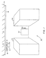
- Fig. 1 is a perspective view of a closed-circuit television surveillance system, using a rail mounted camera, in which the present invention may be applied.
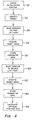
- Fig. 2 is a block diagram of a surveillance system in accordance with the invention.
- Figs. 3A and 3B are respectively top and back isometric schematic diagrams used for explaining initialization and automatic target acquisition procedures carried out in accordance with the invention.
- Fig. 4 is a flow chart of an initialization routine carried out in accordance with the invention.
- Fig. 5 is a flow chart of a routine carried out in accordance with the invention for automatically acquiring a target in response to an alarm signal.
- Fig. 1 shows the interior of a building in which there is installed a surveillance system in accordance with the present invention.
- the system includes a surveillance camera 10 that is mounted on a carriage 12.
- the carriage 12 in turn, is movably supported on an elongated track or rail 14, which is suspended from the ceiling 16 of the building.
- the camera 10 may be of a conventional type which is subject to remote control as to the direction in which the camera is oriented.
- the camera is controllable for horizontal pivoting movement, known as “panning”, as well as vertical pivoting movement known as “tilting”.
- a motorized mirror assembly may be mounted on the carriage in association with the camera 10 for accomplishing tilting and panning adjustments of the direction of view of the camera.
- the carriage 12 includes a motor 18 which is also subject to remote control by the surveillance system.
- Appropriate encoding such as optical encoding (not shown) is provided along the rail 14 so that the position of the carriage 12 along the rail can be sensed and an appropriate carriage position signal provided to the control system.
- other techniques may be employed to determine the position of the carriage, such as detecting operation of motor 18.
- the carriage can be controllably moved to desired positions along the rail 14.
- connections for controlling the camera 10 and the carriage 12 can be via cable (in which case a cable reel carriage may be provided integrated with or separate from camera carriage 12) or by wireless communication links.
- an opaque cover or the like for hiding the camera 10 may be provided surrounding the rail 14 and the path of travel of the carriage 12.
- the building interior shown in Fig. 1 includes a door 20 located at the end of an aisle 22 formed between racks or tiers 24 of merchandise or the like.
- a sensor 26 is installed in proximity to the door 20 and provides an alarm signal when, for example, the door is opened.
- Fig. 2 illustrates the surveillance system of the present invention in block diagram form.
- CPU central processing unit
- microprocessor 30 Associated with the microprocessor 30 are a program memory 32, for storing control software, and a data memory 34 in which working data are stored, including, as will be seen, parameter data collected during an initialization routine.
- CPU 28 also includes an input/output (I/O) module 36 which is connected to microprocessor 30 and provides an interface between the CPU 28 and other portions of the surveillance system.
- I/O input/output
- I/O module 36 is connected by way of a signal path 37 to a pan motor 38, a tilt motor 40, a zoom motor 42 and a rail motor 44.
- Pan motor 38 provides the above-mentioned panning adjustments for the video camera 10
- tilt motor 40 provides the above-mentioned tilt adjustments of the video camera 10
- zoom motor 42 implements changes in the zoom condition of the camera 10
- rail or carriage motor 44 propels the carriage 12 along the rail 14.
- Each of these motors receives control signals from the CPU 28 by way of the I/O module 36 and the signal path 37, and all of these motors are carried on the carriage 12 (although, as an alternative, the carriage 12 may be driven by an off-board motor through a belt drive or the like).
- each of the motors 38, 40, 42, and 44 are arranged to provide position feedback signals indicative of the position of the motor or of the carriage, as the case may be. These signals are transmitted back to the CPU 28 by way of a signal path 46 and I/O module 36.
- the paths 37 and 46 may, for example, be embodied by appropriate caoling, or wireless data channels, etc.
- I/O module 36 Also connected to CPU 28 by way of I/O module 36 are a user terminal 48 and the above-mentioned sensor 26.
- the terminal 48 permits a human operator to input data to the CPU 28 in a conventional manner, and also permits the CPU 28 to display data to the human operator in a conventional manner.
- the I/O module 36 is provided with a communication channel from the sensor 26 for receiving therefrom the above-mentioned alarm signal, upon opening of the door 20 (Fig. 1).
- the surveillance system shown in Fig. 2 provides the customary capabilities for remote control of the camera 10 and carriage 12 by the human operator, including selective positioning of the carriage 12, and panning, tilting and zooming of the camera 10, all by way of signals input via the terminal 48.
- the surveillance system also includes a video display monitor 49 connected (or linked by wireless channel) to receive and display the video output signal provided by the camera 10.
- display 49 is shown as being separate from terminal 48, it is also contemplated to share a monitor portion of terminal 41 with display 49, by means of split screen, windowing, time sharing, superposition of a cursor and characters on the video display, and so forth.
- the rail 14, door 20 and merchandise tiers 24 are positioned with respect to each other so that the door 20 is within a line of sight of the camera 10 over a portion of the rail 12, but when the carriage 12 is positioned outside of that portion of the rail 14, the line of sight from the camera 10 to the door 20 is occluded by, for example, the tiers of merchandise 24.
- the door 20 is a target for which automatic image acquisition is desired. Accordingly, there will first be described an initialization procedure during which appropriate data is stored in the CPU 28 to allow for an automatic target acquisition operation in accordance with the invention.
- Fig. 3A and 3B are respectively top and back diagrammatic views which illustrate geometric relationships among a target (assumed to be door 20), the rail 14 (taken to be the "z-axis"), and various positions along rail 14 at which the carriage 12 may be located.
- the x-axis direction is taken to be the horizontal direction perpendicular to the rail 14, and the y-axis direction is taken to be the vertical direction.
- the horizontal plane which passes through the rail 14 will be referred to as the x-z plane, while the vertical plane which passes through rail 14 will be referred to as the y-z plane.
- Point R1 corresponds to a right-most position on the rail 14 from which there is a line of sight to the target door 20, and point R2 corresponds to the left-most position on the rail 14 from which there is a line of sight to the target door 20.
- a zero-reference or origin point is taken to be at a leftward position along the rail(z-axis), so that the position index of R1 is larger than the position index of R2.
- point Rn represents a position on the rail 14 that is closest to the target 20, and Rz indicates an arbitrary position between points R2 and R1 at which the carriage 12 and camera 10 may be located at any given time.
- the system is arranged so that the camera 12 may at some times be at positions along rail 14 that are outside of the range defined between point R2 and R1.
- the line B1 represents the projection on the x-z plane of the line of sight from point R1 to the target
- the line B2 represents the projection on the x-z plane of the line of sight from point R2 to the target.
- the dashed line Bz similarly represents the projection on the x-z plane of the line of sight from the arbitrary point Rz to the target
- the dotted line N represents the projection of the x-z plane of the line of sight from the point Rn to the target.
- the line segment A2 is defined between the points R2 and Rn, and the line segment A1 is defined between points Rn and R1.
- the line segment A12 is defined between the points Rn and Rz.
- the point Txz is located in the x-z plane directly above the target.
- the angle ⁇ 1 between line B1 and the z axis represents the required pan angle for the camera to acquire the target when the carriage is located at point R1
- the angle ⁇ 2 between the line B2 and the z axis represents the appropriate pan angle for the camera to acquire the target when the carriage is located at the point R2.
- the angle ⁇ z formed between the line Bz and the z axis represents the appropriate pan angle for acquiring the,target when the camera is located at point R z .
- Fig. 3B Reference to Fig. 3B will indicate that the appropriate camera tilt angles for target acquisition from points R2, Rz and R1 are schematically represented by the angles ⁇ 2, ⁇ z and ⁇ 1. It will also be noted from Fig. 3B that the line Dz represents the line of sight from point Rz to the target (not a projection), while the dotted line Y is the projection on the y-z plane of a normal line from the z axis to the target. Thus Y represents the vertical distance between the target and the x-z plane.
- the initialization procedure is commenced at step 50 by entry of an appropriate signal via user terminal 48 so that the microprocessor 30 begins to carry out an initialization routine.
- step 52 at which appropriate data entry is made to identify the target for purposes of future reference within the surveillance system.
- an appropriate prompt may be displayed on the terminal 48, and in response thereto the operator may enter a designation such as "target No. 1".
- target No. 1 the target object for which initialization data is about to be issued will thereafter be referred to within the surveillance system as "target No. 1” and a sensor or sensors associated with that target object will accordingly be recognized by the surveillance system as providing an alarm signal with respect to the identified target object.
- an alarm signal can be actuated with respect to a particular target by an appropriate operator input via the terminal 48. It will be understood that this arrangement permits the surveillance system to provide automatic acquisition for plural targets in response to respective alarm signals pertaining to the targets.
- step 54 at which the terminal 48 is operated so that the carriage is moved to the point at the end (for example at the right end) of a rang of positions along the rail 14 from which the target object may be acquired by the camera 10.
- that point will be identified as R1.
- step 56 is carried out, in which the operator causes the camera's direction of view to be adjusted, and perhaps also adjusts the zoom and focus condition of the camera, so that the target object (door 20) is imaged by the camera 10.
- the human operator When a satisfactory image of the target door 20 has been acquired through the camera 10, the human operator then enters a "select" signal or the like, in response to which the surveillance system stores in data memory 34 data which represents the current position (now assumed to be R1) of the carriage 12, as well as data indicating the pan and tilt angles of the direction of view of the camera 10 (step 58).
- step 60 at which the human operator moves the carriage 12 to the other end of the range from which there is a line of sight to the target door 20. In this case it is assumed that the other end is the left-most end of the viewable range, at point R2.
- the operator again causes the camera direction and zoom/focus conditions to be adjusted so that a satisfactory image of the target door 20 is obtained (step 62). Then, at step 64, again the "select" signal is entered via the terminal 48 so that the data representing the carriage position, as well as the camera direction (pan and tilt angles) is entered into the data memory 34.
- Step 66 follows, at which the position of point Rn is calculated on the basis of the data stored during steps 58 and 64.
- point Rn is assumed to be the optimum point for acquiring an image of the target 20, namely the closest position to the target along rail 14.
- Step 66 may be considered complete upon calculation of the position of the optimum viewpoint Rn.
- the calculated position of Rn together with the stored data indicative of the locations and the appropriate pan and tilt angles for the points R2 and R1, make it possible to calculate an appropriate camera direction (pan and tilt angles) as well as appropriate zoom and focus conditions for target acquisition from any carriage position between points R2 and R1.
- the zoom and focus conditions are a function of the distance from the carriage position to the target, and this quantity can be calculated based on the stored data.
- step 70 may include an automatically controlled procedure in which the carriage 12 is moved along rail 14 according to a predetermined pattern, while the direction, zoom, focus and so forth of the camera 10 are also adjusted in a predetermined pattern so that camera 10 performs routine surveillance by "walking a beat.”
- Step 72 the normal surveillance routine 70 continues until an alarm signal is received.
- Step 72 may be implemented by applying an interrupt to microprocessor 30 upon receipt of an alarm signal. Alternatively, for example, periodic polling may be carried out during normal surveillance to detect the presence of an alarm signal.
- step 74 If an alarm signal is received it is then determined whether the carriage 12 is located within range along the rail 14 from which there is a line of sight to the target (step 74). It will be assumed in the present case, initially, that an alarm signal has been generated by the sensor 26 associated with the door 20 ("target No. 1") and that the carriage 12 is at a point Rz (Figs. 3A and 3B) that is between points R1 and R2, and thus is within the range from which the target 20 can be acquired by the camera 10. In accordance with this assumption, step 76 follows step 74, and in step 76 the surveillance system (CPU 28) calculates an appropriate pan angle tilt angle, zoom condition and focus condition for the camera 10 so that an image of target 20 can be immediately provided on the video display 49.
- pan angle ⁇ z can be readily calculated from the initialization data and the current position Rz.
- Y may be calculated at step 66 of the initializatior routine (Fig. 4).
- the distance Dz from the point Rz to the target along the line of sight from point Rz for the target is calculated.
- the distance to the target from the current position of the camera 10 can be expressed in terms of the current position of the carriage 12 and other data that has previously been stored or calculated. Accordingly, at step 78, which follows step 76, the direction of view of the camera adjusted in accordance with the calculated pan and tilt angles and the appropriate zoom and focus conditions are applied so that the camera 10 provides an image of the target door 20. Then step 80 follows step 78, so that the carriage 12 is moved from the point Rz, at which the carriage was located when the alarm was received, to the optimum viewpoint Rn.
- pan angle, the tilt angle, the zoom condition and the focus condition are continuously updated, by calculations as described above, so that the camera continues to "track" the target; that is, the camera continuously provides an image of the target while the carriage is in motion from point Rz to point Rn.
- step 74 it is determined at step 74 that the carriage 12 is not within the range from which the target can be acquired, and step 82 therefore follows step 74.
- step 82 it is first determined whether the carriage 12 is closer to point R1 or point R2, and then the pan and tilt angles and the zoom and focus conditions for the camera are established in accordance with the previously stored parameters appropriate for that nearest point. Since, according to the present assumption, R1 is the nearest of the two points, the camera is adjusted to have a pan angle ⁇ 1 and a tilt angle ⁇ 1 . It will also be recognized that the appropriate camera focus and zoom conditions for the two limit points R1 and R2 can either be stored as part of the initialization procedure or can be calculated from other data obtained during initialization.
- step 84 at which the carriage 12 is moved toward the nearest limit point, in this case R1. Because the camera has already been adjusted so as to assume the appropriate pan and tilt, etc. for point R1, it will be understood that the target will be acquired immediately when the carriage reaches point R1.
- step 84 is a decision step 86, at which it is determined whether the nearest limit point has been reached. If not, the routine loops back to step 84. Otherwise, the routine proceeds to step 80, at which the carriage is moved from the limit point to optimum position Rn while providing continuous tracking of the target by the camera 10.
- steps 82 and 84 are presented as logically separate, those two steps can be overlapped in time so that the camera angle adjustment is carried out during movement of the carriage 12 toward the nearest point.
- steps 76 and 80 referred to calculations carried out to obtain pan, tilt, zoom and focus data for immediate target acquisition in response to an alarm (step 76) or during carriage movement (step 80) to update the pan and tilt angles and the zoom and focus conditions so that target acquisition was maintained during the carriage movement within the viewing range.
- pan, tilt, zoom and focus data are retrieved for target acquisition from a look up table that was formed during initialization.
- step 66 of the initialization procedure includes calculating, for each separately detectable carriage position in the target viewing range, appropriate pan, tilt, zoom and focus parameters for target acquisition. The resulting data is stored in a look up table for the target, and indexed in the table according to carriage position.
- the parameters stored in the look up table entries for the limit points are, of course, those obtained at steps 58 and 64. Then, during the target acquisition routine of Fig. 5, access is had to the look up table corresponding to the target to be acquired, and camera positioning and focus and zoom data are read out based on the current carriage position. If the current carriage position is outside of the viewing range for the target, the camera positioning data corresponding to the nearest position in the viewing range (i.e., the nearest limit point) is read out.
- the procedure described with respect to step 80 can be changed, or selectively changed, so that the carriage 12 is caused to reciprocate or "pace" back and forth between the points R1 and R2 in response to receipt of an alarm signal. While such "pacing" takes place, calculations as described above are carried out (or positioning data is retrieved from a look up table) so that the camera continuously tracks the target.
- the "pacing” may also be arranged to be performed over less than the entire range from which a line of sight exists. It is also contemplated that the carriage be moved, in response to an alarm, according to more complex patterns than simple pacing between two points in the viewing range.
- the system could be programmed during initialization so that, in response to an alarm, the carriage first paces a predetermined number of times between the optimum viewpoint and the right limit point, and then paces a predetermined number of times between the optimum viewpoint and the left limit point, and then paces again between the optimum viewpoint and the right limit point, and so forth.
- the carriage could be reciprocated several times over a narrow range around the optimum point, then over a wider range around the optimum point, and then over a still wider range.
- Other variations and permutations of such programmed responses to an alarm will readily occur to those who are skilled in the art.
- the above-described practice of the invention entails calculating the location of a closest point Rn to the target to provide an optimum viewpoint
- an alarm signal can be generated from a source other than a sensor.
- an alarm signal can be actuated by appropriate operator input via terminal 48 in a circumstance in which the operator wishes to obtain rapid and automatic acquisition of a particular target.
Description
- This invention relates generally to closed-circuit television surveillance systems and pertains more particularly to such systems in which a television camera is mounted on a carriage for movement along a rail or track, and in which the system is subject to automatic control by a computer or the like.
- It is known to provide closed circuit television surveillance systems using either cameras in a fixed location or cameras that are mounted for movement along a rail or track. It is also known, in the case of a system using a fixed-position camera, to provide automatic acquisition of a fixed target object in response to an alarm signal or the like. For example, a target object such as a door can be equipped with a sensor which provides an alarm signal to a central control portion of the surveillance system when the door is opened. Assuming that data has previously been stored in the control system to indicate the required direction of view and appropriate zoom and/or focus condition for the camera to provide an image of the target door, the control system can implement an immediate adjustment to the camera direction, zoom condition, etc. so that an image of the door is provided by the camera within a very short time after the door is opened.
- However, when the system utilizes a moving camera, such as a camera mounted on a carriage which travels along a rail, the camera may be located at any arbitrary position in its range of movement at the time an alarm is received. Since the camera location at the time of the alarm cannot be known in advance, it is not possible to store in advance data defining a particular direction and zoom condition of the camera which will enable the camera to provide an image of the target from the position of the camera at the time of the alarm.
- In the case of an operator-attended surveillance system, the human operator may attempt to respond to the alarm signal by operating system controls to reposition the camera carriage and to adjust the camera direction, etc. so that an image of the target object is obtained. However, the variety of possible camera positions and directions-of-view may lead to disorientation on the part of the operator. Also, if the system is set up with multiple target objects (e.g., multiple doors, windows, cabinets and so forth) for which alarms may be actuated, the operator may have difficulty identifying the particular target to which the alarm pertains. As a result, the human operator's response to the alarm may be too slow to capture an image of the event (such as entry of an intruder) which caused the alarm.
- While it might be proposed to define a predetermined position along the track to which the camera should be moved in response to an alarm which pertains to a particular target, and then an appropriate direction of view and zoom condition data could also be stored for providing an image of the target from that predetermined position, such an approach carries the disadvantage that a significant amount of time may be required to move the carriage to the predetermined position from the position of the carriage at the time the alarm is received. Even if automatic camera direction and zoom adjustments are performed before or during carriage movement so that the camera will be in an appropriate orientation and zoom condition to provide the image of the target as soon as the predetermined carriage position is reached, still target acquisition cannot take place during the time the carriage is in motion, and target acquisition thus may be substantially delayed.
- US-A-4 510 526 discloses a surveillance system wherein a TV-camera is pivotally mounted along its optical axis on or along a ceiling, and a mirror is pivotally mounted about an axis perpendicular to the optical axis to intercept the view of the camera. Then, by selected rotation of the camera and mirror about these axes, both pan and tilt functions are achieved in a very compact structure. Further this system comprises an open-door sensor which is responsive to a door being opened and provides a signal to a control console, which automatically causes a tilt signal and a pan signal to operate different motors. These motors train the camera and the door and operate the zoom-mechanism of the camera to adjust the focal lens of the camera to the desired field of view.
- The present invention has as its primary object the provision of a closed circuit television surveillance system, using a rail-based television camera, that is capable of acquiring an image of a fixed target within a minimum amount of time after receipt of an alarm signal or the like.
- Another object of the invention is provision of a surveillance system using a rail-mounted camera in which the camera is controlled to continuously track a target while the camera is moving along the rail.
- In attaining the foregoing and other objects, the invention provides a method of operating a rail-based closed-circuit television surveillance system wherein the system includes an elongated track positioned along a path, a carriage supported and movable along the track for transporting a television camera along the path, carriage moving means coupled to the carriage for selectively moving the carriage along the track, camera control means for selectively adjusting a direction of view and a zoom condition of the television camera, and carriage control means for selectively positioning the carriage along the track, and wherein the method includes the steps of initializing the system by capturing an image of a predetermined target object by means of the television camera at respective times when the camera is at two different selected points along the track and storing initialization data indicative of the selected points and the respective directions of view of the camera used for capturing the target object image at the selected points; calculating from the stored initialization data an optimum viewpoint along the track for capturing an image of the predetermined target object and an optimum pan angle, an optimum tilt angle and an optimum zoom condition for capturing the image of. the predetermined target object when the camera is at the optimum viewpoint; receiving a target acquisition signal; and moving the carriage to the optimum viewpoint in response to the target acquisition signal.
- According to an aspect of the invention, the direction of view of the camera is continuously adjusted while the carriage is moved from one of the two selected points to the optimum point so that the direction of view of the camera remains oriented towards the target object during the movement of the carriage from the one of the two selected points to the optimum point.
- It is desirable that the optimum viewpoint be between the selected points used during initialization and that the optimum viewpoint be the closest point along the track to the target object.
- In other practice in accordance with the invention, if the target acquisition signal is received at a time when the carriage is not between the two selected points, the carriage is moved toward the closer of the two points and the direction of view of the camera is adjusted, while the carriage is being moved toward the closer of the two selected points, so that the camera has the same direction of view that was used during the initialization to capture the image of the predetermined target object from the closer of the two selected points.
- It is also contemplated by the invention that the carriage be reciprocated between the two selected points in response to the target acquisition signal and that the direction of view of the camera be continuously adjusted so that the direction of view of the camera remains oriented towards the target object during the reciprocating movement of the carriage.
- The foregoing and other objects and features of the invention will be further understood from the following detailed description of preferred embodiments and practices thereof and from the drawings, wherein like reference numerals identify like components and parts throughout.
- Fig. 1 is a perspective view of a closed-circuit television surveillance system, using a rail mounted camera, in which the present invention may be applied.
- Fig. 2 is a block diagram of a surveillance system in accordance with the invention.
- Figs. 3A and 3B are respectively top and back isometric schematic diagrams used for explaining initialization and automatic target acquisition procedures carried out in accordance with the invention.
- Fig. 4 is a flow chart of an initialization routine carried out in accordance with the invention.
- Fig. 5 is a flow chart of a routine carried out in accordance with the invention for automatically acquiring a target in response to an alarm signal.
- Fig. 1 shows the interior of a building in which there is installed a surveillance system in accordance with the present invention. The system includes a
surveillance camera 10 that is mounted on acarriage 12. Thecarriage 12, in turn, is movably supported on an elongated track orrail 14, which is suspended from theceiling 16 of the building. - The
camera 10 may be of a conventional type which is subject to remote control as to the direction in which the camera is oriented. In particular, the camera is controllable for horizontal pivoting movement, known as "panning", as well as vertical pivoting movement known as "tilting". Alternatively, as will be recognized by those skilled in the art, a motorized mirror assembly may be mounted on the carriage in association with thecamera 10 for accomplishing tilting and panning adjustments of the direction of view of the camera. - The
carriage 12 includes amotor 18 which is also subject to remote control by the surveillance system. Appropriate encoding such as optical encoding (not shown) is provided along therail 14 so that the position of thecarriage 12 along the rail can be sensed and an appropriate carriage position signal provided to the control system. Alternatively, other techniques may be employed to determine the position of the carriage, such as detecting operation ofmotor 18. Thus, the carriage can be controllably moved to desired positions along therail 14. It should be understood that connections for controlling thecamera 10 and thecarriage 12 can be via cable (in which case a cable reel carriage may be provided integrated with or separate from camera carriage 12) or by wireless communication links. - Although not shown in Fig. 1, it will be recognized that an opaque cover or the like for hiding the
camera 10 may be provided surrounding therail 14 and the path of travel of thecarriage 12. - The building interior shown in Fig. 1 includes a
door 20 located at the end of anaisle 22 formed between racks ortiers 24 of merchandise or the like. Asensor 26 is installed in proximity to thedoor 20 and provides an alarm signal when, for example, the door is opened. - Fig. 2 illustrates the surveillance system of the present invention in block diagram form. At the heart of the system is a central processing unit (CPU) 28, which includes a
microprocessor 30. Associated with themicroprocessor 30 are aprogram memory 32, for storing control software, and adata memory 34 in which working data are stored, including, as will be seen, parameter data collected during an initialization routine.CPU 28 also includes an input/output (I/O)module 36 which is connected tomicroprocessor 30 and provides an interface between theCPU 28 and other portions of the surveillance system. - In particular, I/
O module 36 is connected by way of asignal path 37 to apan motor 38, atilt motor 40, a zoom motor 42 and arail motor 44. Panmotor 38 provides the above-mentioned panning adjustments for thevideo camera 10,tilt motor 40 provides the above-mentioned tilt adjustments of thevideo camera 10, zoom motor 42 implements changes in the zoom condition of thecamera 10, and rail orcarriage motor 44 propels thecarriage 12 along therail 14. Each of these motors receives control signals from theCPU 28 by way of the I/O module 36 and thesignal path 37, and all of these motors are carried on the carriage 12 (although, as an alternative, thecarriage 12 may be driven by an off-board motor through a belt drive or the like). It should also be understood that each of themotors CPU 28 by way of a signal path 46 and I/O module 36. Thepaths 37 and 46 may, for example, be embodied by appropriate caoling, or wireless data channels, etc. - Also connected to
CPU 28 by way of I/O module 36 are auser terminal 48 and the above-mentionedsensor 26. Theterminal 48 permits a human operator to input data to theCPU 28 in a conventional manner, and also permits theCPU 28 to display data to the human operator in a conventional manner. Also, the I/O module 36 is provided with a communication channel from thesensor 26 for receiving therefrom the above-mentioned alarm signal, upon opening of the door 20 (Fig. 1). - It should also be understood that the surveillance system shown in Fig. 2 provides the customary capabilities for remote control of the
camera 10 andcarriage 12 by the human operator, including selective positioning of thecarriage 12, and panning, tilting and zooming of thecamera 10, all by way of signals input via theterminal 48. - The surveillance system also includes a video display monitor 49 connected (or linked by wireless channel) to receive and display the video output signal provided by the
camera 10. Althoughdisplay 49 is shown as being separate from terminal 48, it is also contemplated to share a monitor portion of terminal 41 withdisplay 49, by means of split screen, windowing, time sharing, superposition of a cursor and characters on the video display, and so forth. - Referring again to Fig. 1, it will be assumed that the
rail 14,door 20 andmerchandise tiers 24 are positioned with respect to each other so that thedoor 20 is within a line of sight of thecamera 10 over a portion of therail 12, but when thecarriage 12 is positioned outside of that portion of therail 14, the line of sight from thecamera 10 to thedoor 20 is occluded by, for example, the tiers ofmerchandise 24. It is also assumed for the purposes of the,following discussion that thedoor 20 is a target for which automatic image acquisition is desired. Accordingly, there will first be described an initialization procedure during which appropriate data is stored in theCPU 28 to allow for an automatic target acquisition operation in accordance with the invention. - In describing the initialization procedure, reference will be made to Fig. 3A and 3B, which are respectively top and back diagrammatic views which illustrate geometric relationships among a target (assumed to be door 20), the rail 14 (taken to be the "z-axis"), and various positions along
rail 14 at which thecarriage 12 may be located. In the coordinate system used in Figs. 3A and 3B, the x-axis direction is taken to be the horizontal direction perpendicular to therail 14, and the y-axis direction is taken to be the vertical direction. In addition, the horizontal plane which passes through therail 14 will be referred to as the x-z plane, while the vertical plane which passes throughrail 14 will be referred to as the y-z plane. - Point R1 corresponds to a right-most position on the
rail 14 from which there is a line of sight to thetarget door 20, and point R2 corresponds to the left-most position on therail 14 from which there is a line of sight to thetarget door 20. As seen from Figs. 3A and 3B, a zero-reference or origin point is taken to be at a leftward position along the rail(z-axis), so that the position index of R1 is larger than the position index of R2. Further, point Rn represents a position on therail 14 that is closest to thetarget 20, and Rz indicates an arbitrary position between points R2 and R1 at which thecarriage 12 andcamera 10 may be located at any given time. It should also be understood that the system is arranged so that thecamera 12 may at some times be at positions alongrail 14 that are outside of the range defined between point R2 and R1. Further, and referring particularly to Fig. 3A, the line B1 represents the projection on the x-z plane of the line of sight from point R1 to the target, and, similarly, the line B2 represents the projection on the x-z plane of the line of sight from point R2 to the target. The dashed line Bz similarly represents the projection on the x-z plane of the line of sight from the arbitrary point Rz to the target, and the dotted line N represents the projection of the x-z plane of the line of sight from the point Rn to the target. The line segment A2 is defined between the points R2 and Rn, and the line segment A1 is defined between points Rn and R1. In addition, the line segment A12 is defined between the points Rn and Rz. The point Txz is located in the x-z plane directly above the target. - Moreover, the angle 1 between line B1 and the z axis represents the required pan angle for the camera to acquire the target when the carriage is located at point R1, while the angle 2 between the line B2 and the z axis represents the appropriate pan angle for the camera to acquire the target when the carriage is located at the point R2. Similarly, the angle z formed between the line Bz and the z axis represents the appropriate pan angle for acquiring the,target when the camera is located at point Rz.
- Reference to Fig. 3B will indicate that the appropriate camera tilt angles for target acquisition from points R2, Rz and R1 are schematically represented by the angles α2, αz and α1. It will also be noted from Fig. 3B that the line Dz represents the line of sight from point Rz to the target (not a projection), while the dotted line Y is the projection on the y-z plane of a normal line from the z axis to the target. Thus Y represents the vertical distance between the target and the x-z plane.
- Continuing to refer to Figs. 3A and 3B, and also now making reference to Fig. 4, there will be described an initialization routine to be carried out in accordance with the invention for enabling the surveillance system to perform automatic target acquisition.
- As shown in Fig. 4, the initialization procedure is commenced at
step 50 by entry of an appropriate signal viauser terminal 48 so that themicroprocessor 30 begins to carry out an initialization routine. - Following
step 50 isstep 52, at which appropriate data entry is made to identify the target for purposes of future reference within the surveillance system. For example, an appropriate prompt may be displayed on the terminal 48, and in response thereto the operator may enter a designation such as "target No. 1". In other words, the target object for which initialization data is about to be issued will thereafter be referred to within the surveillance system as "target No. 1" and a sensor or sensors associated with that target object will accordingly be recognized by the surveillance system as providing an alarm signal with respect to the identified target object. It is also contemplated that an alarm signal can be actuated with respect to a particular target by an appropriate operator input via theterminal 48. It will be understood that this arrangement permits the surveillance system to provide automatic acquisition for plural targets in response to respective alarm signals pertaining to the targets. - The next step in the initialization routine is.
step 54, at which the terminal 48 is operated so that the carriage is moved to the point at the end (for example at the right end) of a rang of positions along therail 14 from which the target object may be acquired by thecamera 10. For the purposes of this example, that point will be identified as R1. For example, such a point may be a short distance to the right ofaisle 22 as shown in Fig. 1. Oncestep 54 has been accomplished,step 56 is carried out, in which the operator causes the camera's direction of view to be adjusted, and perhaps also adjusts the zoom and focus condition of the camera, so that the target object (door 20) is imaged by thecamera 10. When a satisfactory image of thetarget door 20 has been acquired through thecamera 10, the human operator then enters a "select" signal or the like, in response to which the surveillance system stores indata memory 34 data which represents the current position (now assumed to be R1) of thecarriage 12, as well as data indicating the pan and tilt angles of the direction of view of the camera 10 (step 58). - Following
step 58 isstep 60, at which the human operator moves thecarriage 12 to the other end of the range from which there is a line of sight to thetarget door 20. In this case it is assumed that the other end is the left-most end of the viewable range, at point R2. - When the carriage has been properly positioned at R2, the operator again causes the camera direction and zoom/focus conditions to be adjusted so that a satisfactory image of the
target door 20 is obtained (step 62). Then, atstep 64, again the "select" signal is entered via the terminal 48 so that the data representing the carriage position, as well as the camera direction (pan and tilt angles) is entered into thedata memory 34. -
Step 66 follows, at which the position of point Rn is calculated on the basis of the data stored duringsteps target 20, namely the closest position to the target alongrail 14. - This calculation begins by determining the values for angle for T1 and T2 (Fig. 3A) which are respectively complimentary angles to 1 and 2. Thus, calculations are made according to the following formulas:
- Then a parameter k1 is calculated according to the formula
- It will be recognized that the parameter k is equal to the ratio of the lengths of the line segments A1 and A2; that is,
- Next the distance Z between the points R1 and R2 is calculated according to:
- Since
- Then Rn can be calculated either as (R1 - A1) or (R2 + A2).
Step 66 may be considered complete upon calculation of the position of the optimum viewpoint Rn. - As will be seen, the calculated position of Rn, together with the stored data indicative of the locations and the appropriate pan and tilt angles for the points R2 and R1, make it possible to calculate an appropriate camera direction (pan and tilt angles) as well as appropriate zoom and focus conditions for target acquisition from any carriage position between points R2 and R1. It will be understood that the zoom and focus conditions are a function of the distance from the carriage position to the target, and this quantity can be calculated based on the stored data.
- There will now be described, with reference to Fig. 5, an operation in which the surveillance system automatically acquires an image of the target on the basis of the data stored and calculated during the initialization procedure of Fig. 4.
- It is assumed that the automatic target acquisition routine is entered from a normal surveillance routine, represented by a
step 70 in Fig. 5. Specifically, it should be understood thatstep 70 may include an automatically controlled procedure in which thecarriage 12 is moved alongrail 14 according to a predetermined pattern, while the direction, zoom, focus and so forth of thecamera 10 are also adjusted in a predetermined pattern so thatcamera 10 performs routine surveillance by "walking a beat." - As indicated at
step 72, thenormal surveillance routine 70 continues until an alarm signal is received.Step 72 may be implemented by applying an interrupt tomicroprocessor 30 upon receipt of an alarm signal. Alternatively, for example, periodic polling may be carried out during normal surveillance to detect the presence of an alarm signal. If an alarm signal is received it is then determined whether thecarriage 12 is located within range along therail 14 from which there is a line of sight to the target (step 74). It will be assumed in the present case, initially, that an alarm signal has been generated by thesensor 26 associated with the door 20 ("target No. 1") and that thecarriage 12 is at a point Rz (Figs. 3A and 3B) that is between points R1 and R2, and thus is within the range from which thetarget 20 can be acquired by thecamera 10. In accordance with this assumption,step 76 followsstep 74, and instep 76 the surveillance system (CPU 28) calculates an appropriate pan angle tilt angle, zoom condition and focus condition for thecamera 10 so that an image oftarget 20 can be immediately provided on thevideo display 49. - First the calculation of the pan angle z will be described with reference to Fig. 3A. Using the common side of the triangles Rn/R1/Txz and Rn/Rz/Txz, the following equation can be obtained:
- This equation can be rewritten as
- Since
equation 10 that the pan angle z can be calculated as follows: - From equation 11, it will be recognized that the pan angle z can be readily calculated from the initialization data and the current position Rz.
- Alternatively, z can be calculated according to the following equation:
- In order to find the tilt angle αz (Fig. 3B), the vertical distance Y between the target and the x-z plane is first calculated according to the formula:
- (As an alternative to calculating Y during automatic target acquisition, Y may be calculated at
step 66 of the initializatior routine (Fig. 4).) - Then αz is determined according to:
- Next, in order to determine the appropriate zoom and focus conditions for the
camera 10, the distance Dz from the point Rz to the target along the line of sight from point Rz for the target is calculated. - First it will be noted that

- Then, since Bz = A12/cos z,
substituting inequation 16, provides
- Thus it is seen that the distance to the target from the current position of the
camera 10 can be expressed in terms of the current position of thecarriage 12 and other data that has previously been stored or calculated. Accordingly, atstep 78, which followsstep 76, the direction of view of the camera adjusted in accordance with the calculated pan and tilt angles and the appropriate zoom and focus conditions are applied so that thecamera 10 provides an image of thetarget door 20. Then step 80 followsstep 78, so that thecarriage 12 is moved from the point Rz, at which the carriage was located when the alarm was received, to the optimum viewpoint Rn. Also, while this carriage movement is taking place, the pan angle, the tilt angle, the zoom condition and the focus condition are continuously updated, by calculations as described above, so that the camera continues to "track" the target; that is, the camera continuously provides an image of the target while the carriage is in motion from point Rz to point Rn. - As will be recognized by those of ordinary skill in the art the above described calculations and adjustments to the camera direction, zoom condition, etc. are performed quite rapidly relative to the motion of the carriage, which makes possible the continuous tracking of the target by the camera. Of course, it is also possible to overlap in time the logically separate operations described above with respect to
steps - Returning now to
decision step 74, let it be assumed that, at the time the alarm signal was received, thecarriage 12 was positioned outside of the range defined by points R2 and R1, and more specifically, assume that thecarriage 12 was located to the right of point R1. - In that case, it is determined at
step 74 that thecarriage 12 is not within the range from which the target can be acquired, and step 82 therefore followsstep 74. Atstep 82, it is first determined whether thecarriage 12 is closer to point R1 or point R2, and then the pan and tilt angles and the zoom and focus conditions for the camera are established in accordance with the previously stored parameters appropriate for that nearest point. Since, according to the present assumption, R1 is the nearest of the two points, the camera is adjusted to have a pan angle 1 and a tilt angle α1. It will also be recognized that the appropriate camera focus and zoom conditions for the two limit points R1 and R2 can either be stored as part of the initialization procedure or can be calculated from other data obtained during initialization. - Following
step 82 is step 84, at which thecarriage 12 is moved toward the nearest limit point, in this case R1. Because the camera has already been adjusted so as to assume the appropriate pan and tilt, etc. for point R1, it will be understood that the target will be acquired immediately when the carriage reaches point R1. - Following step 84 is a
decision step 86, at which it is determined whether the nearest limit point has been reached. If not, the routine loops back to step 84. Otherwise, the routine proceeds to step 80, at which the carriage is moved from the limit point to optimum position Rn while providing continuous tracking of the target by thecamera 10. - It should also be noted that although
steps 82 and 84 are presented as logically separate, those two steps can be overlapped in time so that the camera angle adjustment is carried out during movement of thecarriage 12 toward the nearest point. - The above description of
steps steps - According to an alternative technique for practicing the invention, the procedure described with respect to step 80 can be changed, or selectively changed, so that the
carriage 12 is caused to reciprocate or "pace" back and forth between the points R1 and R2 in response to receipt of an alarm signal. While such "pacing" takes place, calculations as described above are carried out (or positioning data is retrieved from a look up table) so that the camera continuously tracks the target. The "pacing" may also be arranged to be performed over less than the entire range from which a line of sight exists. It is also contemplated that the carriage be moved, in response to an alarm, according to more complex patterns than simple pacing between two points in the viewing range. For example, the system could be programmed during initialization so that, in response to an alarm, the carriage first paces a predetermined number of times between the optimum viewpoint and the right limit point, and then paces a predetermined number of times between the optimum viewpoint and the left limit point, and then paces again between the optimum viewpoint and the right limit point, and so forth. As an alternative "beat" that could be programmed to be "walked" in response to an alarm, the carriage could be reciprocated several times over a narrow range around the optimum point, then over a wider range around the optimum point, and then over a still wider range. Other variations and permutations of such programmed responses to an alarm will readily occur to those who are skilled in the art. - Further, although the above-described practice of the invention entails calculating the location of a closest point Rn to the target to provide an optimum viewpoint, it is possible as an alternative to manually set the desired optimum viewpoint during initialization. For example, if some obstruction happens to block the line of sight from the closest point Rn to the target, a different point can be manually selected and appropriate pan, tilt and zoom data stored.
- It should also be understood that an alarm signal can be generated from a source other than a sensor. For example, an alarm signal can be actuated by appropriate operator input via
terminal 48 in a circumstance in which the operator wishes to obtain rapid and automatic acquisition of a particular target. - Various changes to the foregoing surveillance system and modifications in the described practices may be introduced without departing from the invention. The particularly preferred methods and apparatus are thus intended in an illustrative and not limiting sense. The scope of the invention is set forth in the following claims.
Claims (28)
- A surveillance system comprising:an elongated track positioned along a path;carriage means supported on and movable along said track for transporting a television camera (10) along said path;carriage moving means coupled to said carriage means for selectively moving said carriage means along said track;means associated with said television camera (10) and responsive to camera control signals for selectively adjusting a direction of view and a zoom condition of said television camera (10);carriage control means coupled to said carriage moving means and responsive to carriage control signals for selectively positioning said carriage means along said track; andfirst and second sets of initialization parameters andinitialization means for entering both first and second sets of initialization parameters, said first set of initialization parameters including first position data representative of a first selected point along said elongated track and first camera direction data representative of a first camera direction selected so that said television camera (10) provides an image of a predetermined target object when said carriage means is positioned at said first selected point, said second set of initialization parameters including second position data representative of a second selected point along said elongated track and second camera direction data representative of a second camera direction selected so that said television camera provides an image of said predetermined target object when said carriage means is positioned at said second selected point.
- A surveillance system according to claim 1, wherein each of said sets of initialization parameters includes respective pan and tilt data.
- A surveillance system according to claim 2, wherein said initialization means includes select means operable by a human operator for actuating a parameter storage operation and means, responsive to operation of said select means by said human operator, for detecting and storing parameter data representative of a position of said carriage means and a direction of view and a zoom condition of said television camera (10) at a time when said select means is operated.
- A surveillance system according to claim 1, wherein said first and second selected points define therebetween a range of positions along said rail at which said camera (10) can be oriented to provide an image of said predetermined target object.
- A surveillance system according to claim 4, further comprising target means operatively connected to said carriage control means for receiving a target acquisition signal and for responding to the received target acquisition signal by generating carriage control signals such that said carriage control means moves said carriage means to a predetermined position in said range of positions between said first and second selected points.
- A surveillance system according to claim 5, further comprising means operatively connected to said camera control means for responding to the received target acquisition control signal by generating camera control signals based on said entered initialization parameters to adjust the direction of view and zoom condition of said television camera (10) during movement of said carriage means in said range of positions so that said television camera (10) continuously proyides an image of said predetermined target object during such movement of said carriage means in said range of positions.
- A surveillance system according to claim 6, further comprising:means for calculating, based on said entered initialization parameters, and for each one of a plurality of positions between said first and second selected points, an appropriate pan angle, an appropriate tilt angle and an appropriate zoom condition for enabling said television camera (10) to provide an image of said predetermined target object when said carriage means is positioned at the respective one of said plurality of positions; andmeans for storing data representative of the calculated pan and tilt angles and zoom conditions in a look up table indexed according to said plurality of positions.
- A surveillance system according to claim 5, further comprising means operatively connected to said camera control means for responding to the received target acquisition signal by generating camera control signals in accordance with a selected one of said first and second camera direction data, if said carriage means is not positioned within said range of positions at a time when said target acquisition signal is received.
- A surveillance system according to claim 8, wherein:if, at said time when said target acquisition signal is received, said carriage means is positioned outside of said range of positions and closer to said first selected point than to said second selected point, then said camera control means causes the direction of view of said television camera to become said first selected camera direction in response to said received target acquisition signal; andif, at said time when said target acquisition signal is received, said carriage means is positioned outside of said range of positions and closer to said second selected point than to said first selected point, then said camera control means causes the direction of view of said television camera to become said second selected camera direction in response to said received target acquisition signal.
- A surveillance system according to claim 5, wherein said predetermined position is at a closest point to said predetermined target object along said rail, and further comprising means for calculating, on the basis of said first and second sets of initialization parameters, said closest point and an optimum direction of view and an optimum zoom condition for causing said television camera (10) to provide an image of said predetermined target object when said carriage means is positioned at said closest point.
- A surveillance system according to claim 5, further comprising sensor means for providing said target acquisition signal to said target means in response to a change in a physical condition at said predetermined target object.
- A surveillance system according to claim 4, further comprising means operatively connected to said carriage control means and to said camera control means for receiving a target acquisition signal and for responding to the received target acquisition signal by generating carriage control signals such that said carriage control means moves said carriage means to reciprocate between two predetermined points of said range of positions defined by said first and second selected points and for generating camera control signals during such reciprocating movement of said carriage means to adjust the direction of view and zoom condition of said television camera (10) so that said television camera (10) continuously provides an image of said predetermined target object during such reciprocating movement.
- A surveillance system according to claim 12, wherein said two predetermined points between which said carriage means is reciprocated are said first and second selected points.
- A method of initializing a rail-based closed circuit television surveillance system, the surveillance system including an elongated track positioned along a path, carriage means supported on and movable along said track for transporting a television camera (10) along said path, carriage moving means coupled to said carriage means for selectively moving said carriage means along said track, camera control means for selectively adjusting a direction of view and a zoom condition of said television camera (10), and carriage control means for selectively positioning said carriage means along said track, the method comprising the steps of:positioning said carriage means at a first selected point along said elongated track;orienting the direction of view of said television camera (10) in a first orientation so that said television camera (10) provides an image of a predetermined target object at a time when said carriage means is at said first selected point;storing a first set of initialization parameters which includes first track position data representative of said first selected point and first camera direction data representative of said first orientation of the direction of view of said television camera (10);positioning said carriage means at a second selected point along said track;orienting the direction of view of said television camera (10) in a second orientation so that said television camera (10) provides an image of said predetermined target object at a time when said carriage means is at said second selected point; andstoring a second set of initialization parameters which includes second track position data representative of said second selected point and second camera direction data representative of said second orientation of the direction of view of said television camera (10).
- An initialization method according to claim 14, wherein said first camera direction data includes first pan angle data and first tilt angle data and said second camera direction data includes second pan angle data and second tilt angle data.
- An initialization method according to claim 15, further comprising the step of calculating on the basis of said stored first and second sets of initialization parameters an optimum viewpoint along said track that is closest to said target object.
- An initialization method according to claim 16, further comprising the step of calculating, on the basis of said stored first and second sets of parameters, an optimum pan angle, an optimum tilt angle and an optimum zoom condition for enabling said television camera (10) to provide an image of said predetermined target object when said carriage means is positioned at said optimum viewpoint.
- An initialization method according to claim 17, wherein said step of calculating said optimum zoom condition includes calculating a distance between said predetermined target object and said optimum viewpoint.
- An initialization method according to claim 14, further comprising the steps of:calculating on the basis of said stored first and second sets of initialization parameters, and for each one of a plurality of positions between said first and second selected points, an appropriate pan angle, an appropriate tilt angle and an appropriate zoom condition for enabling said television camera (10) to provide an image of said predetermined target object when said carriage means is positioned at the respective one of said plurality of positions; andstoring data representative of the calculated pan and tilt angles and zoom conditions in a look up table indexed according to said plurality of positions.
- A method according to claim 14, further comprising the step of:calculating from the stored initialization data an optimum viewpoint along said path for capturing an image of said predetermined target object, and an optimum pan angle, an optimum tilt angle and an optimum zoom condition for capturing said image of said predetermined target object when said camera (10) is at said optimum viewpoint;receiving a target acquisition signal; andmoving said camera (10) to said optimum viewpoint in response to said received target acquisition signal.
- A method according to claim 20, wherein said step of moving said camera (10) to said optimum viewpoint includes moving said camera (10) towards said optimum viewpoint along a range of positions between said two selected points, and further comprising the step of adjusting the direction of view and zoom condition of said camera (10) during such movement of said camera (10) along said range of positions so that said camera (10) continuously provides an image of said predetermined target object during such movement of said camera (10) in said range of positions.
- A method according to claim 21, wherein said initializing step includes calculating on the basis of said stored initialization data, and for each one of a plurality of positions between said two selected points, an appropriate pan angle, an appropriate tilt angle and an appropriate zoom condition for enabling said television camera (10) to provide an image of said predetermined target object when said camera (10) is positioned at the respective one of said plurality of positions, and storing data representative of the calculated pan and tilt angles and zoom conditions in a look up table indexed according to said plurality of positions.
- A method according to claim 20, wherein said optimum viewpoint is between said two selected points and is closer to said predetermined target object than any other point along said path.
- A method according to claim 20, wherein said target acquisition signal is received at a time when said camera (10) is not between said two selected points on said path, and said moving step includes moving said camera (10) toward a closer one of said two selected points, and further comprising the step of adjusting the direction of view of said camera (10), at the same time said camera (10) is being moved towards said closer one of said two selected points, said adjusting step being carried out so that the camera (10) has the same direction of view that was used during said initialization step to capture the image of the predetermined target object from said closer one of said two selected points.
- A method according to claim 20, further comprising the step of moving said camera (10) according to a predetermined pattern in response to said received target acquisition signal.
- A method according to claim 25, further comprising the step of continuously adjusting the direction of view of said camera (10) during said movement of said camera (10) according to said predetermined pattern so that said direction of view remains oriented towards said target object during said movement of said camera (10).
- A method according to claim 26, wherein said movement of said camera (10) according to said predetermined pattern includes reciprocating said camera (10) between two predetermined points.
- A method according to claim 27, wherein said two predetermined points between which said camera (10) is reciprocated are said two selected points.
Applications Claiming Priority (2)
| Application Number | Priority Date | Filing Date | Title |
|---|---|---|---|
| US302341 | 1994-09-07 | ||
| US08/302,341 US5526041A (en) | 1994-09-07 | 1994-09-07 | Rail-based closed circuit T.V. surveillance system with automatic target acquisition |
Publications (3)
| Publication Number | Publication Date |
|---|---|
| EP0701232A2 EP0701232A2 (en) | 1996-03-13 |
| EP0701232A3 EP0701232A3 (en) | 1997-12-10 |
| EP0701232B1 true EP0701232B1 (en) | 2002-04-17 |
Family
ID=23167346
Family Applications (1)
| Application Number | Title | Priority Date | Filing Date |
|---|---|---|---|
| EP95112903A Expired - Lifetime EP0701232B1 (en) | 1994-09-07 | 1995-08-17 | Rail-based closed circuit T.V. surveillance system with automatic target acquisition |
Country Status (6)
| Country | Link |
|---|---|
| US (1) | US5526041A (en) |
| EP (1) | EP0701232B1 (en) |
| JP (1) | JPH0888847A (en) |
| BR (1) | BR9503950A (en) |
| CA (1) | CA2149730C (en) |
| DE (1) | DE69526397T2 (en) |
Families Citing this family (92)
| Publication number | Priority date | Publication date | Assignee | Title |
|---|---|---|---|---|
| US8352400B2 (en) | 1991-12-23 | 2013-01-08 | Hoffberg Steven M | Adaptive pattern recognition based controller apparatus and method and human-factored interface therefore |
| US6628887B1 (en) | 1998-04-17 | 2003-09-30 | Honeywell International, Inc. | Video security system |
| EP0776573A4 (en) * | 1994-07-26 | 1998-04-15 | Maxpro Systems Pty Ltd | A video security system |
| US5872594A (en) * | 1994-09-20 | 1999-02-16 | Thompson; Paul A. | Method for open loop camera control using a motion model to control camera movement |
| FR2725062B1 (en) * | 1994-09-23 | 1997-04-04 | Douard Pierre Rene | METHOD AND DEVICE FOR REMOTE MONITORING BY MOBILE TRACK CAMERAS |
| CA2155719C (en) * | 1994-11-22 | 2005-11-01 | Terry Laurence Glatt | Video surveillance system with pilot and slave cameras |
| JP3347510B2 (en) * | 1995-03-13 | 2002-11-20 | キヤノン株式会社 | Image input device |
| US8574074B2 (en) | 2005-09-30 | 2013-11-05 | Sony Computer Entertainment America Llc | Advertising impression determination |
| US7895076B2 (en) | 1995-06-30 | 2011-02-22 | Sony Computer Entertainment Inc. | Advertisement insertion, profiling, impression, and feedback |
| WO1997022918A1 (en) * | 1995-12-20 | 1997-06-26 | Mediamaxx Incorporated | Computer-controlled system for producing three-dimensional navigable photographs of areas and method thereof |
| US5844601A (en) * | 1996-03-25 | 1998-12-01 | Hartness Technologies, Llc | Video response system and method |
| US5953055A (en) * | 1996-08-08 | 1999-09-14 | Ncr Corporation | System and method for detecting and analyzing a queue |
| US20030020824A1 (en) * | 1996-10-24 | 2003-01-30 | Yujiro Ito | Camera apparatus |
| JP3943674B2 (en) * | 1996-10-25 | 2007-07-11 | キヤノン株式会社 | Camera control system, camera server and control method thereof |
| EP1450306A3 (en) | 1996-10-31 | 2009-07-15 | Sensormatic Electronics Corporation | Intelligent video information management system |
| DE19651172C2 (en) * | 1996-12-10 | 2003-08-28 | Dag Auerbach | monitoring system |
| US6727938B1 (en) * | 1997-04-14 | 2004-04-27 | Robert Bosch Gmbh | Security system with maskable motion detection and camera with an adjustable field of view |
| US6577339B1 (en) * | 1997-07-30 | 2003-06-10 | Pinotage, Llc | Aircraft monitoring and analysis system and method |
| US6685366B1 (en) * | 1997-09-05 | 2004-02-03 | Robert Bosch Gmbh | Camera positioning system with optimized field of view |
| WO1999035850A1 (en) * | 1997-12-31 | 1999-07-15 | Koninklijke Philips Electronics N.V. | Multiple camera system |
| US7755668B1 (en) | 1998-04-09 | 2010-07-13 | Johnston Gregory E | Mobile surveillance system |
| JPH11331822A (en) * | 1998-05-15 | 1999-11-30 | Matsushita Electric Ind Co Ltd | Monitor camera system |
| US6189838B1 (en) * | 1998-06-02 | 2001-02-20 | Sentry Technology, Corp. | Position detector for track mounted surveillance systems |
| JP2000083188A (en) * | 1998-09-03 | 2000-03-21 | Matsushita Electric Ind Co Ltd | Monitoring camera device |
| US7904187B2 (en) | 1999-02-01 | 2011-03-08 | Hoffberg Steven M | Internet appliance system and method |
| DE29903350U1 (en) * | 1999-02-24 | 1999-04-22 | Nordmann Kurt Dr | Monitoring system |
| JP4243883B2 (en) * | 1999-03-15 | 2009-03-25 | フジノン株式会社 | Remote head system |
| US6285297B1 (en) * | 1999-05-03 | 2001-09-04 | Jay H. Ball | Determining the availability of parking spaces |
| AU762221B2 (en) * | 1999-05-06 | 2003-06-19 | Lextar Technologies Limited | A surveillance system |
| AUPQ017199A0 (en) | 1999-05-06 | 1999-05-27 | Lextar Technologies Limited | A system for surveillance of an area |
| JP2001069496A (en) * | 1999-08-31 | 2001-03-16 | Matsushita Electric Ind Co Ltd | Supervisory camera apparatus and control method for supervisory camera |
| US7995096B1 (en) * | 1999-09-23 | 2011-08-09 | The Boeing Company | Visual security operations system |
| DE60040051D1 (en) * | 1999-12-03 | 2008-10-09 | Fujinon Corp | Automatic follower |
| MXPA02009776A (en) * | 2000-04-03 | 2004-09-06 | Pugliese Company | System and method for displaying and selling goods and services. |
| US7151562B1 (en) * | 2000-08-03 | 2006-12-19 | Koninklijke Philips Electronics N.V. | Method and apparatus for external calibration of a camera via a graphical user interface |
| US8751310B2 (en) | 2005-09-30 | 2014-06-10 | Sony Computer Entertainment America Llc | Monitoring advertisement impressions |
| US6995788B2 (en) * | 2001-10-10 | 2006-02-07 | Sony Computer Entertainment America Inc. | System and method for camera navigation |
| JP3754320B2 (en) * | 2001-05-18 | 2006-03-08 | 三洋電機株式会社 | Image signal processing device |
| US20020196342A1 (en) * | 2001-06-21 | 2002-12-26 | Walker Jay S. | Methods and systems for documenting a player's experience in a casino environment |
| US20050064926A1 (en) | 2001-06-21 | 2005-03-24 | Walker Jay S. | Methods and systems for replaying a player's experience in a casino environment |
| IL150123A0 (en) * | 2002-06-10 | 2003-07-06 | Shahar Avneri | Security system |
| US20050134685A1 (en) * | 2003-12-22 | 2005-06-23 | Objectvideo, Inc. | Master-slave automated video-based surveillance system |
| US20100002070A1 (en) | 2004-04-30 | 2010-01-07 | Grandeye Ltd. | Method and System of Simultaneously Displaying Multiple Views for Video Surveillance |
| US7528881B2 (en) * | 2003-05-02 | 2009-05-05 | Grandeye, Ltd. | Multiple object processing in wide-angle video camera |
| US20080274798A1 (en) * | 2003-09-22 | 2008-11-06 | Walker Digital Management, Llc | Methods and systems for replaying a player's experience in a casino environment |
| US20050104958A1 (en) * | 2003-11-13 | 2005-05-19 | Geoffrey Egnal | Active camera video-based surveillance systems and methods |
| US7051938B2 (en) * | 2003-12-29 | 2006-05-30 | Motorola, Inc. | System and method for a multi-directional imaging system |
| DE102004018410A1 (en) * | 2004-04-16 | 2005-11-03 | Robert Bosch Gmbh | Safety system and method for its operation |
| US8427538B2 (en) * | 2004-04-30 | 2013-04-23 | Oncam Grandeye | Multiple view and multiple object processing in wide-angle video camera |
| FR2870075B1 (en) * | 2004-05-05 | 2006-08-04 | Hymatom Sa | VIDEOSURVEILLANCE SYSTEM WITH FIXED CAMERAS AND MOBILE CAMERA IN ROTATION AND TRANSLATION |
| US7623156B2 (en) * | 2004-07-16 | 2009-11-24 | Polycom, Inc. | Natural pan tilt zoom camera motion to preset camera positions |
| US8763157B2 (en) | 2004-08-23 | 2014-06-24 | Sony Computer Entertainment America Llc | Statutory license restricted digital media playback on portable devices |
| DE102004043816B4 (en) * | 2004-09-08 | 2006-08-31 | Paulussen Systems Gmbh | Video surveillance system and method of operation |
| US20060071933A1 (en) | 2004-10-06 | 2006-04-06 | Sony Computer Entertainment Inc. | Application binary interface for multi-pass shaders |
| US7189909B2 (en) * | 2004-11-23 | 2007-03-13 | Román Viñoly | Camera assembly for finger board instruments |
| US8416299B2 (en) * | 2005-06-20 | 2013-04-09 | Lextar Pty Ltd. | Directional surveillance camera with ring of directional detectors |
| US7636126B2 (en) | 2005-06-22 | 2009-12-22 | Sony Computer Entertainment Inc. | Delay matching in audio/video systems |
| ATE477565T1 (en) * | 2005-06-30 | 2010-08-15 | Planum Vision Ltd | MONITORING SYSTEM AND METHOD FOR DETECTING PROHIBITED MOTION ON A PREDETERMINED PATH |
| JP5030776B2 (en) * | 2005-07-01 | 2012-09-19 | 株式会社Access | Terminal device, terminal device program, and broadcast program scene notification system |
| US9363487B2 (en) * | 2005-09-08 | 2016-06-07 | Avigilon Fortress Corporation | Scanning camera-based video surveillance system |
| US20070058717A1 (en) * | 2005-09-09 | 2007-03-15 | Objectvideo, Inc. | Enhanced processing for scanning video |
| US8626584B2 (en) | 2005-09-30 | 2014-01-07 | Sony Computer Entertainment America Llc | Population of an advertisement reference list |
| US10657538B2 (en) | 2005-10-25 | 2020-05-19 | Sony Interactive Entertainment LLC | Resolution of advertising rules |
| US8676900B2 (en) | 2005-10-25 | 2014-03-18 | Sony Computer Entertainment America Llc | Asynchronous advertising placement based on metadata |
| US11004089B2 (en) | 2005-10-25 | 2021-05-11 | Sony Interactive Entertainment LLC | Associating media content files with advertisements |
| US20070118425A1 (en) | 2005-10-25 | 2007-05-24 | Podbridge, Inc. | User device agent for asynchronous advertising in time and space shifted media network |
| WO2007084766A2 (en) * | 2006-01-20 | 2007-07-26 | Wms Gaming Inc. | Wagering game with symbol strings dictating winning outcomes |
| US7965859B2 (en) | 2006-05-04 | 2011-06-21 | Sony Computer Entertainment Inc. | Lighting control of a user environment via a display device |
| US7880746B2 (en) | 2006-05-04 | 2011-02-01 | Sony Computer Entertainment Inc. | Bandwidth management through lighting control of a user environment via a display device |
| CN103279874B (en) | 2006-05-05 | 2016-08-03 | 美国索尼电脑娱乐公司 | Advertisement rotation |
| US8416247B2 (en) | 2007-10-09 | 2013-04-09 | Sony Computer Entertaiment America Inc. | Increasing the number of advertising impressions in an interactive environment |
| US8769558B2 (en) | 2008-02-12 | 2014-07-01 | Sony Computer Entertainment America Llc | Discovery and analytics for episodic downloaded media |
| GB2458661A (en) * | 2008-03-26 | 2009-09-30 | Sasan Yadrandji Aghdam | Remote-controlled rail-mounted IP camera |
| JP5072733B2 (en) * | 2008-06-25 | 2012-11-14 | キヤノン株式会社 | IMAGING DEVICE AND IMAGING DEVICE CONTROL METHOD |
| US8763090B2 (en) | 2009-08-11 | 2014-06-24 | Sony Computer Entertainment America Llc | Management of ancillary content delivery and presentation |
| US10786736B2 (en) | 2010-05-11 | 2020-09-29 | Sony Interactive Entertainment LLC | Placement of user information in a game space |
| JP2012069022A (en) * | 2010-09-27 | 2012-04-05 | Hitachi Ltd | Monitoring system |
| US8791911B2 (en) | 2011-02-09 | 2014-07-29 | Robotzone, Llc | Multichannel controller |
| DE102011014552A1 (en) * | 2011-03-21 | 2012-09-27 | Rwe Deutschland Ag | Construction site container and method for remote site monitoring using at least one construction site container |
| ITMI20110473A1 (en) * | 2011-03-25 | 2012-09-26 | Special Projects Snc Di Ferdinando Garetti E Franc | MACHINE FOR HANDLING PROFESSIONAL HIGH-SPEED CAMERAS WITH ROTATION MOVEMENT ON THE AXIS OF THE OPTIC, LINEAR FEED WITH AUTOMATED FOCUSING SYSTEM. |
| US9390617B2 (en) * | 2011-06-10 | 2016-07-12 | Robotzone, Llc | Camera motion control system with variable autonomy |
| US9342817B2 (en) | 2011-07-07 | 2016-05-17 | Sony Interactive Entertainment LLC | Auto-creating groups for sharing photos |
| US9286516B2 (en) | 2011-10-20 | 2016-03-15 | Xerox Corporation | Method and systems of classifying a vehicle using motion vectors |
| US9171213B2 (en) | 2013-03-15 | 2015-10-27 | Xerox Corporation | Two-dimensional and three-dimensional sliding window-based methods and systems for detecting vehicles |
| US8971581B2 (en) | 2013-03-15 | 2015-03-03 | Xerox Corporation | Methods and system for automated in-field hierarchical training of a vehicle detection system |
| US9726463B2 (en) | 2014-07-16 | 2017-08-08 | Robtozone, LLC | Multichannel controller for target shooting range |
| US20200404175A1 (en) * | 2015-04-14 | 2020-12-24 | ETAK Systems, LLC | 360 Degree Camera Apparatus and Monitoring System |
| US10846779B2 (en) | 2016-11-23 | 2020-11-24 | Sony Interactive Entertainment LLC | Custom product categorization of digital media content |
| US10860987B2 (en) | 2016-12-19 | 2020-12-08 | Sony Interactive Entertainment LLC | Personalized calendar for digital media content-related events |
| US10931991B2 (en) | 2018-01-04 | 2021-02-23 | Sony Interactive Entertainment LLC | Methods and systems for selectively skipping through media content |
| JP7235853B2 (en) * | 2018-08-30 | 2023-03-08 | キヤノンバージニア, インコーポレイテッド | Autonomous surveillance system |
| CN112750062A (en) * | 2019-10-31 | 2021-05-04 | 比亚迪股份有限公司 | Passenger service control method and system for station and terminal equipment |
Family Cites Families (14)
| Publication number | Priority date | Publication date | Assignee | Title |
|---|---|---|---|---|
| US4644845A (en) * | 1972-05-18 | 1987-02-24 | Garehime Jacob W Jr | Surveillance and weapon system |
| US4027329A (en) * | 1974-12-06 | 1977-05-31 | Coutta John M | Surveillance system |
| US3935380A (en) * | 1974-12-06 | 1976-01-27 | Coutta John M | Surveillance system |
| US4337482A (en) * | 1979-10-17 | 1982-06-29 | Coutta John M | Surveillance system |
| US4326218A (en) * | 1980-11-14 | 1982-04-20 | Coutta John M | Surveillance system |
| US4510526A (en) * | 1983-04-19 | 1985-04-09 | Coutta John M | Surveillance system |
| FR2633134A1 (en) * | 1988-06-15 | 1989-12-22 | Boucher Bernard | Video monitoring installation |
| DE3902076C1 (en) * | 1989-01-25 | 1990-08-23 | Messerschmitt-Boelkow-Blohm Gmbh, 8012 Ottobrunn, De | |
| US5109278A (en) * | 1990-07-06 | 1992-04-28 | Commonwealth Edison Company | Auto freeze frame display for intrusion monitoring system |
| KR930010843B1 (en) * | 1990-12-15 | 1993-11-12 | 삼성전자 주식회사 | Mobil camera apparatus |
| US5241380A (en) * | 1991-05-31 | 1993-08-31 | Video Sentry Corporation | Track mounted surveillance system having multiple use conductors |
| US5225863A (en) * | 1991-08-15 | 1993-07-06 | Weir Jones Iain | Remotely operated camera system with battery recharging system |
| JPH07104835A (en) * | 1993-10-07 | 1995-04-21 | Hitachi Ltd | Device for controlling, analyzing and operating mobile check robot system |
| JP3084647B2 (en) * | 1993-12-27 | 2000-09-04 | 株式会社日立製作所 | Drawing management device |
-
1994
- 1994-09-07 US US08/302,341 patent/US5526041A/en not_active Expired - Lifetime
-
1995
- 1995-05-18 CA CA002149730A patent/CA2149730C/en not_active Expired - Lifetime
- 1995-08-17 DE DE69526397T patent/DE69526397T2/en not_active Expired - Lifetime
- 1995-08-17 EP EP95112903A patent/EP0701232B1/en not_active Expired - Lifetime
- 1995-09-06 BR BR9503950A patent/BR9503950A/en not_active IP Right Cessation
- 1995-09-07 JP JP7254518A patent/JPH0888847A/en active Pending
Also Published As
| Publication number | Publication date |
|---|---|
| EP0701232A3 (en) | 1997-12-10 |
| CA2149730C (en) | 2005-10-04 |
| DE69526397D1 (en) | 2002-05-23 |
| EP0701232A2 (en) | 1996-03-13 |
| US5526041A (en) | 1996-06-11 |
| BR9503950A (en) | 1996-09-24 |
| CA2149730A1 (en) | 1996-03-08 |
| DE69526397T2 (en) | 2002-11-28 |
| JPH0888847A (en) | 1996-04-02 |
Similar Documents
| Publication | Publication Date | Title |
|---|---|---|
| EP0701232B1 (en) | Rail-based closed circuit T.V. surveillance system with automatic target acquisition | |
| KR100660762B1 (en) | Figure tracking in a multiple camera system | |
| US5745166A (en) | Video security system field of the invention | |
| EP0907940B1 (en) | A security system with maskable motion detection and camera with an adjustable field of view | |
| JP4699040B2 (en) | Automatic tracking control device, automatic tracking control method, program, and automatic tracking system | |
| US5980123A (en) | System and method for detecting an intruder | |
| US20050071046A1 (en) | Surveillance system and surveillance robot | |
| WO1999045511A1 (en) | A combined wide angle and narrow angle imaging system and method for surveillance and monitoring | |
| RU83675U1 (en) | VIDEO MONITORING SYSTEM | |
| WO2003100726A1 (en) | Security camera system for tracking moving objects in both forward and reverse directions | |
| WO1991002287A1 (en) | Surveillance camera system | |
| KR20030046323A (en) | Object tracking method and apparatus using template matching | |
| US20030103138A1 (en) | Video security and control system | |
| JP3681543B2 (en) | Surveillance camera device | |
| US20040114037A1 (en) | Camera apparatus, a camera system, and a method for controlling the camera system | |
| JPH09179984A (en) | Video monitor device | |
| JP2003158664A (en) | Camera controller | |
| JP3615867B2 (en) | Automatic camera system | |
| JPH09322053A (en) | Image pickup method for object in automatic image pickup camera system | |
| JPH11142958A (en) | Method and system for automatically controlling posture of built-in camera in automatic information processor | |
| JPH11275566A (en) | Monitoring camera apparatus | |
| JP6725041B2 (en) | Tracking system, tracking method and tracking program | |
| JPH1066057A (en) | Remote supervisory equipment | |
| KR100198143B1 (en) | Guard apparatus | |
| JP3336626B2 (en) | Monitoring device |
Legal Events
| Date | Code | Title | Description |
|---|---|---|---|
| PUAI | Public reference made under article 153(3) epc to a published international application that has entered the european phase |
Free format text: ORIGINAL CODE: 0009012 |
|
| AK | Designated contracting states |
Kind code of ref document: A2 Designated state(s): DE FR GB SE |
|
| PUAL | Search report despatched |
Free format text: ORIGINAL CODE: 0009013 |
|
| AK | Designated contracting states |
Kind code of ref document: A3 Designated state(s): DE FR GB SE |
|
| 17P | Request for examination filed |
Effective date: 19980528 |
|
| 17Q | First examination report despatched |
Effective date: 20000620 |
|
| GRAG | Despatch of communication of intention to grant |
Free format text: ORIGINAL CODE: EPIDOS AGRA |
|
| GRAG | Despatch of communication of intention to grant |
Free format text: ORIGINAL CODE: EPIDOS AGRA |
|
| GRAH | Despatch of communication of intention to grant a patent |
Free format text: ORIGINAL CODE: EPIDOS IGRA |
|
| RAP1 | Party data changed (applicant data changed or rights of an application transferred) |
Owner name: SENSORMATIC ELECTRONICS CORPORATION |
|
| REG | Reference to a national code |
Ref country code: GB Ref legal event code: IF02 |
|
| GRAH | Despatch of communication of intention to grant a patent |
Free format text: ORIGINAL CODE: EPIDOS IGRA |
|
| GRAA | (expected) grant |
Free format text: ORIGINAL CODE: 0009210 |
|
| AK | Designated contracting states |
Kind code of ref document: B1 Designated state(s): DE FR GB SE |
|
| REF | Corresponds to: |
Ref document number: 69526397 Country of ref document: DE Date of ref document: 20020523 |
|
| ET | Fr: translation filed | ||
| PLBE | No opposition filed within time limit |
Free format text: ORIGINAL CODE: 0009261 |
|
| STAA | Information on the status of an ep patent application or granted ep patent |
Free format text: STATUS: NO OPPOSITION FILED WITHIN TIME LIMIT |
|
| 26N | No opposition filed |
Effective date: 20030120 |
|
| PGFP | Annual fee paid to national office [announced via postgrant information from national office to epo] |
Ref country code: SE Payment date: 20030821 Year of fee payment: 9 |
|
| REG | Reference to a national code |
Ref country code: FR Ref legal event code: CA |
|
| PG25 | Lapsed in a contracting state [announced via postgrant information from national office to epo] |
Ref country code: SE Free format text: LAPSE BECAUSE OF NON-PAYMENT OF DUE FEES Effective date: 20040818 |
|
| REG | Reference to a national code |
Ref country code: GB Ref legal event code: 732E |
|
| EUG | Se: european patent has lapsed | ||
| REG | Reference to a national code |
Ref country code: GB Ref legal event code: 732E Free format text: REGISTERED BETWEEN 20101111 AND 20101117 |
|
| REG | Reference to a national code |
Ref country code: FR Ref legal event code: TP Owner name: SENSORMATIC ELECTRONICS, LLC, US Effective date: 20110913 |
|
| REG | Reference to a national code |
Ref country code: DE Ref legal event code: R082 Ref document number: 69526397 Country of ref document: DE Representative=s name: HAFNER & PARTNER, DE |
|
| REG | Reference to a national code |
Ref country code: DE Ref legal event code: R082 Ref document number: 69526397 Country of ref document: DE Representative=s name: HAFNER & PARTNER, DE Effective date: 20130612 Ref country code: DE Ref legal event code: R081 Ref document number: 69526397 Country of ref document: DE Owner name: TYCO FIRE & SECURITY GMBH, CH Free format text: FORMER OWNER: SENSORMATIC ELECTRONICS, LLC, BOCA RATON, FLA., US Effective date: 20130612 Ref country code: DE Ref legal event code: R081 Ref document number: 69526397 Country of ref document: DE Owner name: TYCO FIRE & SECURITY GMBH, CH Free format text: FORMER OWNER: SENSORMATIC ELECTRONICS, LLC, BOCA RATON, US Effective date: 20130612 |
|
| PGFP | Annual fee paid to national office [announced via postgrant information from national office to epo] |
Ref country code: DE Payment date: 20140827 Year of fee payment: 20 |
|
| PGFP | Annual fee paid to national office [announced via postgrant information from national office to epo] |
Ref country code: GB Payment date: 20140827 Year of fee payment: 20 Ref country code: FR Payment date: 20140818 Year of fee payment: 20 |
|
| REG | Reference to a national code |
Ref country code: DE Ref legal event code: R071 Ref document number: 69526397 Country of ref document: DE |
|
| REG | Reference to a national code |
Ref country code: GB Ref legal event code: PE20 Expiry date: 20150816 |
|
| PG25 | Lapsed in a contracting state [announced via postgrant information from national office to epo] |
Ref country code: GB Free format text: LAPSE BECAUSE OF EXPIRATION OF PROTECTION Effective date: 20150816 |