EP0701125A2 - Sensor - Google Patents
Sensor Download PDFInfo
- Publication number
- EP0701125A2 EP0701125A2 EP95112572A EP95112572A EP0701125A2 EP 0701125 A2 EP0701125 A2 EP 0701125A2 EP 95112572 A EP95112572 A EP 95112572A EP 95112572 A EP95112572 A EP 95112572A EP 0701125 A2 EP0701125 A2 EP 0701125A2
- Authority
- EP
- European Patent Office
- Prior art keywords
- housing
- solid electrolyte
- electrolyte tube
- sensor according
- thickening
- Prior art date
- Legal status (The legal status is an assumption and is not a legal conclusion. Google has not performed a legal analysis and makes no representation as to the accuracy of the status listed.)
- Withdrawn
Links
- 239000007784 solid electrolyte Substances 0.000 claims abstract description 30
- 239000000919 ceramic Substances 0.000 claims abstract description 11
- 229910052751 metal Inorganic materials 0.000 claims abstract description 6
- 239000002184 metal Substances 0.000 claims abstract description 6
- 230000008719 thickening Effects 0.000 claims description 17
- 239000004020 conductor Substances 0.000 claims description 14
- 238000002485 combustion reaction Methods 0.000 claims description 9
- 238000010438 heat treatment Methods 0.000 claims description 3
- 239000004922 lacquer Substances 0.000 claims description 3
- 230000007704 transition Effects 0.000 claims description 2
- 239000003973 paint Substances 0.000 claims 1
- 239000007789 gas Substances 0.000 abstract description 20
- BASFCYQUMIYNBI-UHFFFAOYSA-N platinum Chemical compound [Pt] BASFCYQUMIYNBI-UHFFFAOYSA-N 0.000 abstract description 8
- 229910052697 platinum Inorganic materials 0.000 abstract description 3
- 229910000831 Steel Inorganic materials 0.000 abstract description 2
- MCMNRKCIXSYSNV-UHFFFAOYSA-N ZrO2 Inorganic materials O=[Zr]=O MCMNRKCIXSYSNV-UHFFFAOYSA-N 0.000 abstract description 2
- 230000007797 corrosion Effects 0.000 abstract description 2
- 238000005260 corrosion Methods 0.000 abstract description 2
- RVTZCBVAJQQJTK-UHFFFAOYSA-N oxygen(2-);zirconium(4+) Chemical compound [O-2].[O-2].[Zr+4] RVTZCBVAJQQJTK-UHFFFAOYSA-N 0.000 abstract description 2
- 239000010959 steel Substances 0.000 abstract description 2
- 239000001301 oxygen Substances 0.000 description 7
- 229910052760 oxygen Inorganic materials 0.000 description 7
- QVGXLLKOCUKJST-UHFFFAOYSA-N atomic oxygen Chemical compound [O] QVGXLLKOCUKJST-UHFFFAOYSA-N 0.000 description 6
- UFHFLCQGNIYNRP-UHFFFAOYSA-N Hydrogen Chemical compound [H][H] UFHFLCQGNIYNRP-UHFFFAOYSA-N 0.000 description 4
- 239000001257 hydrogen Substances 0.000 description 4
- 229910052739 hydrogen Inorganic materials 0.000 description 4
- 238000005259 measurement Methods 0.000 description 3
- UGFAIRIUMAVXCW-UHFFFAOYSA-N Carbon monoxide Chemical compound [O+]#[C-] UGFAIRIUMAVXCW-UHFFFAOYSA-N 0.000 description 2
- 229910002091 carbon monoxide Inorganic materials 0.000 description 2
- 229910001020 Au alloy Inorganic materials 0.000 description 1
- OKTJSMMVPCPJKN-UHFFFAOYSA-N Carbon Chemical compound [C] OKTJSMMVPCPJKN-UHFFFAOYSA-N 0.000 description 1
- 229910001260 Pt alloy Inorganic materials 0.000 description 1
- 229910052799 carbon Inorganic materials 0.000 description 1
- 238000007084 catalytic combustion reaction Methods 0.000 description 1
- 238000006243 chemical reaction Methods 0.000 description 1
- 238000013461 design Methods 0.000 description 1
- 230000007613 environmental effect Effects 0.000 description 1
- 239000011521 glass Substances 0.000 description 1
- 239000003353 gold alloy Substances 0.000 description 1
- 238000003780 insertion Methods 0.000 description 1
- 230000037431 insertion Effects 0.000 description 1
- 238000009434 installation Methods 0.000 description 1
- 238000012544 monitoring process Methods 0.000 description 1
- -1 oxygen ions Chemical class 0.000 description 1
- 230000002787 reinforcement Effects 0.000 description 1
Images


Classifications
-
- G—PHYSICS
- G01—MEASURING; TESTING
- G01N—INVESTIGATING OR ANALYSING MATERIALS BY DETERMINING THEIR CHEMICAL OR PHYSICAL PROPERTIES
- G01N27/00—Investigating or analysing materials by the use of electric, electrochemical, or magnetic means
- G01N27/26—Investigating or analysing materials by the use of electric, electrochemical, or magnetic means by investigating electrochemical variables; by using electrolysis or electrophoresis
- G01N27/403—Cells and electrode assemblies
- G01N27/406—Cells and probes with solid electrolytes
- G01N27/407—Cells and probes with solid electrolytes for investigating or analysing gases
-
- G—PHYSICS
- G01—MEASURING; TESTING
- G01N—INVESTIGATING OR ANALYSING MATERIALS BY DETERMINING THEIR CHEMICAL OR PHYSICAL PROPERTIES
- G01N27/00—Investigating or analysing materials by the use of electric, electrochemical, or magnetic means
- G01N27/26—Investigating or analysing materials by the use of electric, electrochemical, or magnetic means by investigating electrochemical variables; by using electrolysis or electrophoresis
- G01N27/403—Cells and electrode assemblies
- G01N27/406—Cells and probes with solid electrolytes
- G01N27/4062—Electrical connectors associated therewith
Definitions
- the invention relates to a sensor for controlling exhaust gases from combustion plants and internal combustion engines according to the preamble of claim 1.
- the invention has for its object to show a sensor which has a compact structure, can be easily installed in the exhaust duct of combustion systems or internal combustion engines, and is also suitable for the simultaneous measurement of several exhaust gas components.
- the core of the sensor according to the invention is formed by a measuring device with a solid electrolyte tube, on the outer surfaces of which two measuring electrodes are arranged. These are acted upon by the exhaust gas to be checked.
- a reference electrode which is surrounded by a reference gas, is arranged in the interior of the solid electrolyte tube.
- the entire sensor is delimited by a metallic housing which is designed as a cylinder. This housing serves as an installation aid and at the same time as an electrical connection element for the reference electrode of the sensor.
- the cylindrical design of the housing makes it easy to install the sensor in every exhaust duct.
- the electrical connection elements of the measuring electrodes are passed through holes in the solid electrolyte tube into the interior of the solid electrolyte tube and from there are also isolated through the interior of the housing to the outside.
- the measuring device of the sensor sits on a shoulder inside the housing and is held inside the housing with the aid of additional cylindrical components. After insertion of the measuring device, the housing is closed at its first end by the holding elements which are provided for fastening the measuring device in the housing. At the second end, the case remains open. As a result, the exhaust gas to be checked can flow into the interior of the housing and reach the measuring electrodes of the sensor.
- the sensor 1 shown in FIG. 1 is formed by a measuring device 2 and a housing 3. As shown in FIG. 3, the housing 3 is cylindrical. It is made from a corrosion-resistant and electrically conductive material. A steel that is resistant to high temperatures is preferably used for this.
- the measuring device 2 of the sensor 1 has a solid electrolyte tube 4 made of ceramic, which is closed at its first end 4A and at its second end 4B is open.
- the oxygen-ion-conducting solid electrolyte tube 4 is preferably made of zirconium dioxide. At its upper open end 4B, the solid electrolyte tube 4 is provided with an outwardly facing flange-shaped thickening 5 or reinforcement.
- the outer diameter of the solid electrolyte tube 4 is approximately 7 to 10 mm, while the thickening 5 has an outer diameter of 10 to 14 mm.
- a reference electrode 6 is permanently arranged on the inner surface of the solid electrolyte tube 4. It is formed by a platinum layer with defined dimensions.
- a conductor track 7 is provided for the electrical connection of the reference electrode 6. This is guided on the inner surface of the solid electrolyte tube 4 up to the surface 5S of the thickening 5. From there, it is guided outside along the lateral boundary 5E of the thickening 5 to the underside 5U thereof. In the transition area between the solid electrolyte tube 4 and the thickening 5, a lacquer ring 8 is applied, onto which the conductor track 7 is guided.
- the lacquer ring 8 is immediately followed by a metal ring 9.
- This is made of a good electrically conductive material.
- Two measuring electrodes 10 and 11 are arranged on the outer surface 4S of the solid electrolyte tube 5 at a defined distance from one another.
- the measuring electrode 10 is oxidation-catalytically active and is therefore suitable for determining the oxygen content in the exhaust gas. It is made of platinum.
- the measuring electrode 11 is oxidation-catalytically inactive, but electro-catalytically active and is therefore used to determine the hydrogen or carbon monoxide content. It is made from a platinum / gold alloy. At the three-phase boundary gas / measuring electrode / solid electrolyte there is a charge exchange across the interface.
- the measuring electrode 11 is catalytically active. Hydrogen and / or carbon contained in the exhaust gas is oxidized at this measuring electrode. The oxygen not consumed in the catalytic combustion reacts with the oxygen vacancies in the grid of the solid electrolyte, likewise an electrical potential is generated. Therefore, two potentials are formed between the measuring electrodes 10 and 11 and the reference electrode 6. The oxygen content in the exhaust gas is determined from the potential between the measuring electrode 10 and the reference electrode 6.
- the hydrogen and / or carbon monoxide content in the exhaust gas is determined from the potential between the measuring electrode 11 and the reference electrode 6, the information about the determined oxygen content in the exhaust gas being used for this calculation.
- the electrical connection of the measuring electrodes 10 and 11 to the outside takes place initially via conductor tracks 12 and 13 which are permanently connected to the measuring electrodes 10 and 11.
- the conductor tracks 12 and 13 are arranged on the inner surface of the solid electrolyte tube 4.
- the solid electrolyte tube 4 is provided with bores 14, via which the conductor tracks 12 are guided from the inner region 4I of the solid electrolyte tube 4 to the surface 4S of the solid electrolyte 4 to the measuring electrodes 10 and 11.
- the bores 14 are permanently closed with a glass 14G after the connection of the conductor tracks 12 and 13 to the measuring electrodes 10 and 11.
- the conductor tracks 12 and 13 are guided upwards on the inner surface of the solid electrolyte tube 4 up to the surface 5S of the thickened portion 5.
- 5 connecting elements 15 and 16 are placed on the surface 5S of the thickening, which are designed as half rings.
- the dimensions of the connecting elements 15 and 16 are chosen so that they do not touch.
- the connection elements 15 and 16 are permanently connected to electrical lines 15L and 16L via web-shaped components 15A and 16A.
- the components 15 A and 16 A are bent in a semicircle, placed vertically on the inner edge of the connecting elements 15 and 16 and permanently attached there.
- the measuring device 2 forming the sensor 1 is inserted into the metallic housing 3 shown in FIG. 3.
- the length of the housing 3 is selected such that the closed end 4A of the solid electrolyte tube 4 is slightly exceeded by the end 3A of the housing 3.
- the housing 3 has an inner diameter which is slightly larger than the outer diameter of the solid electrolyte tube 4. This ensures that what is to be monitored Exhaust gas can flow around the two measuring electrodes 10 and 11 on the outer surface 4S of the solid electrolyte tube 4 in sufficient quantity.
- the inside diameter 3D of the housing 3 is in the region of the thickening 5 adapted to the outer diameter of the thickening 5.
- the inside diameter 3D is flared at the bottom of the thickening 5, so that a bevel 3S is formed, on which the metal ring 9 is placed.
- the measuring device 2 is optimally held within the housing 3 by supporting the metal ring 9 on the bevel 3S. This also creates a very good electrically conductive connection between the reference electrode 6 and the housing 3 .
- the diameter 3D of the housing 3 is widened again by a few mm toward the second end 3B of the housing 3.
- a cylindrical, insulating component 20 made of ceramic is placed on the connection elements 15 and 16.
- the inner and outer dimensions of the component 20 are adapted to the inner and outer dimensions of the connection elements 15 and 16.
- the component 20 is additionally held in the desired position by edge boundaries 15B and 16B, which are arranged on the outer edge of the connection elements 15 and 16.
- a further cylindrical, insulating component 21 made of ceramic is provided.
- this component 21 is selected such that it directly adjoins the component 20 and has a direct contact with the inner surface 3I of the housing 3 with its outer surface.
- a cylindrical heating element 23 is inserted into the opening of the thickening 5.
- the electrical lines 15L and 16L are conducted to the outside together with the electrical lines 24 of the heating element 23 via a cylindrical and electrically non-conductive ceramic body 25.
- the ceramic body 25 is provided with bores 26, through which the lines 15L and 16L and 24 are passed.
- the longitudinal axis of the ceramic body 25 lies on the same straight line as the longitudinal axis of the housing 3.
Landscapes
- Chemical & Material Sciences (AREA)
- Life Sciences & Earth Sciences (AREA)
- Health & Medical Sciences (AREA)
- Physics & Mathematics (AREA)
- Chemical Kinetics & Catalysis (AREA)
- Electrochemistry (AREA)
- Molecular Biology (AREA)
- Analytical Chemistry (AREA)
- Biochemistry (AREA)
- General Health & Medical Sciences (AREA)
- General Physics & Mathematics (AREA)
- Immunology (AREA)
- Pathology (AREA)
- Measuring Oxygen Concentration In Cells (AREA)
Abstract
Description
Die Erfindung bezieht sich auf einen Sensor zur Kontrolle von Abgasen aus Verbrennungsanlagen und Verbrennungsmotoren gemäß dem Oberbegriff des Patentanspruches 1.The invention relates to a sensor for controlling exhaust gases from combustion plants and internal combustion engines according to the preamble of claim 1.
Zur Energieeinsparung und Vermeidung von Umweltschäden ist eine Überwachung bzw. Regelung von Verbrennungsprozessen nötig. Die Messung des Sauerstoffgehalts in den Abgasen alleine kann kein Hinweis auf eine unvollständige Verbrennung liefern. Vielmehr ist es besonders wichtig, den Anteil der bei der unvollständigen Verbrennung auftretenden oxidierbaren Gase kontrollieren zu können. Die bis jetzt bekannten Sensoren sind teilweise nicht in der Lage, die im Abgas enthalten Komponenten gleichzeitig zu messen. Aus der DE-A-40 21 929 ist zwar ein Sensor bekannt, der eine solche Messung ermöglicht, jedoch weist er einen sehr komplexen Aufbau auf, und ist beim Einbau in Abgaskanäle schwer zu handhaben.In order to save energy and avoid environmental damage, monitoring or regulation of combustion processes is necessary. The measurement of the oxygen content in the exhaust gases alone cannot provide an indication of incomplete combustion. Rather, it is particularly important to be able to control the proportion of the oxidizable gases that occur during incomplete combustion. The sensors known to date are sometimes unable to measure the components contained in the exhaust gas at the same time. From DE-A-40 21 929 a sensor is known which enables such a measurement, but it has a very complex structure and is difficult to handle when installed in exhaust gas ducts.
Der Erfindung liegt die Aufgabe zugrunde, einen Sensor aufzuzeigen, der einen kompakten Aufbau aufweist, auf einfache Weise in den Abgaskanal von Verbrennungsanlagen oder Verbrennungsmaschinen eingebaut werden kann, und zudem für die gleichzeitige Messung von mehreren Abgaskomponenten geeignet ist.The invention has for its object to show a sensor which has a compact structure, can be easily installed in the exhaust duct of combustion systems or internal combustion engines, and is also suitable for the simultaneous measurement of several exhaust gas components.
Diese Aufgabe wird erfindungsgemäß durch die Merkmale des Patentanspruches 1 gelöst.This object is achieved by the features of claim 1.
Den Kern des erfindungsgemäßen Sensors bildet eine Meßvorrichtung mit einem Festelektrolytrohr, auf dessen Außenflächen zwei Meßelektroden angeordnet sind. Diese werden von dem zu überprüfenden Abgas beaufschlagt. Im Inneren des Festelektrolytrohres ist eine Referenzelektrode angeordnet, die von einem Referenzgas umgeben ist. Der gesamte Sensor wird von einem metallischen Gehäuse begrenzt, das als Zylinder ausgebildet ist. Dieses Gehäuse dient als Einbauhilfe und gleichzeitig als elektrisches Anschlußelement für die Referenzelektrode des Sensors. Durch die zylinderförmige Gestaltung des Gehäuses ist ein einfacher Einbau des Sensors in jeden Abgaskanal möglich. Die elektrischen Anschlußelemente der Meßelektroden werden isoliert durch Bohrungen im Festelektrolytrohr hindurch in das Innere des Festelektrolytrohres geleitet und von dort ebenfalls isoliert durch das Innere des Gehäuses nach außen geführt. Die Meßvorrichtung des Sensors sitzt auf einem Absatz innerhalb des Gehäuses und wird mit Hilfe von zusätzlichen zylindrischen Bauelementen im Inneren des Gehäuses gehalten. Nach dem Einsetzen der Meßvorrichtung ist das Gehäuse an seinem ersten Ende durch die Halteelemente verschlossen, die zur Befestigung der Meßvorrichtung im Gehäuse vorgesehen sind. Am zweiten Ende bleibt das Gehäuse offen. Hierdurch kann das zu überprüfende Abgas in das Innere des Gehäuses strömen und zu den Meßelektroden des Sensors gelangen. Weitere erfindungswesentliche Merkmale sind in den Unteransprüchen gekennzeichnet.The core of the sensor according to the invention is formed by a measuring device with a solid electrolyte tube, on the outer surfaces of which two measuring electrodes are arranged. These are acted upon by the exhaust gas to be checked. A reference electrode, which is surrounded by a reference gas, is arranged in the interior of the solid electrolyte tube. The entire sensor is delimited by a metallic housing which is designed as a cylinder. This housing serves as an installation aid and at the same time as an electrical connection element for the reference electrode of the sensor. The cylindrical design of the housing makes it easy to install the sensor in every exhaust duct. The electrical connection elements of the measuring electrodes are passed through holes in the solid electrolyte tube into the interior of the solid electrolyte tube and from there are also isolated through the interior of the housing to the outside. The measuring device of the sensor sits on a shoulder inside the housing and is held inside the housing with the aid of additional cylindrical components. After insertion of the measuring device, the housing is closed at its first end by the holding elements which are provided for fastening the measuring device in the housing. At the second end, the case remains open. As a result, the exhaust gas to be checked can flow into the interior of the housing and reach the measuring electrodes of the sensor. Further features essential to the invention are characterized in the subclaims.
Die Erfindung wird nachfolgend anhand von Zeichnungen näher erläutert.The invention is explained in more detail below with reference to drawings.
Es zeigen:
- Fig. 1 einen erfindungsgemäßen Sensor,
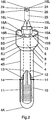
- Fig. 2 die Meßvorrichtung des Sensors,
- Fig. 3 das Gehäuse des Sensors im Vertikalschnitt.
- 1 shows a sensor according to the invention,
- 2 the measuring device of the sensor,
- Fig. 3 shows the housing of the sensor in vertical section.
Der in Fig. 1 dargestellte Sensor 1 wird durch eine Meßvorrichtung 2 und ein Gehäuse 3 gebildet. Das Gehäuse 3 ist, wie Fig. 3 zeigt, zylinderförmig ausgebildet. Es wird aus einem korrosionsbeständigen und elektrisch gut leitenden Material hergestellt. Hierfür wird vorzugsweise ein Stahl verwendet, der gegenüber hohen Temperaturen beständig ist. Die Meßvorrichtung 2 des Sensors 1 weist ein Festelektrolytrohr 4 aus Keramik auf, das an seinem ersten Ende 4A geschlossen und an seinem zweiten Ende 4B offen ist. Das sauerstoffionenleitende Festelektrolytrohr 4 ist vorzugsweise aus Zirkoniumdioxid gefertigt. An seinem oberen offenen Ende 4B ist das Festelektrolytrohr 4 mit einer nach außen weisenden flanschförmigen Verdickung 5 bzw. Verstärkung versehen. Bei dem hier dargestellten Ausführungsbeispiel beträgt der Außendurchmesser des Festelektrolytrohres 4 etwa 7 bis 10mm, während die Verdickung 5 einen Außendurchmesser von 10 bis 14mm aufweist. Auf der Innenfläche des Festelektrolytrohres 4 ist eine Referenzelektrode 6 dauerhaft angeordnet. Sie wird durch eine Platinschicht mit definierten Abmessungen gebildet. Für den elektrischen Anschluß der Referenzelektrode 6 ist eine Leiterbahn 7 vorgesehen. Diese ist auf der Innenfläche des Festelektrolytrohres 4 bis auf die Oberfläche 5S der Verdickung 5 geführt. Von dort ist sie außen an der seitlichen Begrenzung 5E der Verdickung 5 entlang bis zu deren Unterseite 5U geführt. Im Übergangsbereich zwischen dem Festelektrolytrohr 4 und der Verdickung 5 ist ein Lackring 8 aufgetragen, auf den die Leiterbahn 7 geführt ist. An den Lackring 8 schließt sich, wie Fig. 1 zeigt, unmittelbar ein Metallring 9 an. Dieser ist aus einem gut elektrisch leitenden Material gefertigt. Auf der Außenfläche 4S des Festelektrolytrohres 5 sind in definiertem Abstand voneinander zwei Meßelektroden 10 und 11 angeordnet. Die Meßelektrode 10 ist oxidationskatalytisch aktiv und daher zur Ermittlung des Sauerstoffgehaltes im Abgas geeignet. Sie wird aus Platin gefertigt. Die Meßelektrode 11 ist oxidationskatalytisch inaktiv, jedoch elektrokatalytisch aktiv und wird deshalb zur Bestimmung des Wasserstoff- bzw. Kohlenmonoxidgehaltes verwendet. Sie wird aus einer Platin/Gold-Legierung hergestellt. An der Dreiphasengrenze Gas/Meßelektrode/Festelektrolyt kommt es zu einem Ladungsaustausch über die Grenzfläche hinweg. Zwischen der Meßelektrode 11 und der Referenzelektrode wird ein elektrisches Potential ausgebildet, da es zwischen dem Wasserstoff und den im Gitter des Festelektrolytrohres 4 enthaltenen Sauerstoffionen zu einer Reaktion kommt. Dabei werden Elektronen frei. Die Meßelektrode 10 ist katalytisch aktiv. Im Abgas enthaltener Wasserstoff und/oder Kohlenstoff wird an dieser Meßelektrode oxidiert. Der bei der katalytischen Verbrennung nicht verbrauchte Sauerstoff reagiert mit den Sauerstoffleerstellen im Gitter des Festelektrolyten, wobei ebenfalls ein elektrisches Potential erzeugt wird. Es kommt deshalb zur Ausbildung von zwei Potentialen zwischen den Meßelektroden 10 und 11 und der Referenzelektrode 6. Aus dem Potential zwischen der Meßelektrode 10 und der Referenzelektrode 6 wird der Sauerstoffgehalt im Abgas bestimmt. Aus dem Potential zwischen der Meßelektrode 11 und der Referenzelektrode 6 wird der Wasserstoff- und/oder Kohlenmonoxidgehalt im Abgas bestimmt, wobei für diese Berechnung die Information über den ermittelten Sauerstoffgehalt im Abgas verwendet wird. Die elektrische Verbindung der Meßelektroden 10 und 11 nach außen erfolgt zunächst über Leiterbahnen 12 und 13, die mit den Meßelektroden 10 und 11 dauerhaft verbunden sind. Die Leiterbahnen 12 und 13 sind auf der Innenfläche des Festelektrolytrohres 4 angeordnet. Das Festelektrolytrohr 4 ist mit Bohrungen 14 versehen, über welche die Leiterbahnen 12 aus dem Innenbereich 4I des Festelektrolytrohres 4 auf die Oberfläche 4S des Festelektrolyten 4 zu den Meßelektroden 10 und 11 geleitet sind. Die Bohrungen 14 werden nach der Verbindung der Leiterbahnen 12 und 13 mit den Meßelektroden 10 und 11 mit einem Glas 14G dauerhaft verschlossen. Die Leiterbahnen 12 und 13 sind auf der Innenfläche des Festelektrolytrohres 4 nach oben bis auf die Oberfläche 5S der Verdickung 5 geführt. Wie Fig. 2 zeigt, sind auf die Oberfläche 5S der Verdickung 5 Anschlußelemente 15 und 16 aufgesetzt, die als Halbringe ausgebildet sind. Die Abmessungen der Anschlußelemente 15 und 16 sind so gewählt, daß sie sich nicht berühren. Die Anschlußelemente 15 und 16 sind über stegförmige Bauelemente 15A und 16A mit elektrischen Leitungen 15L und 16L dauerhaft verbunden. Die Bauelemente 15 A und 16 A sind halbkreisförmig gebogen, senkrecht auf den inneren Rand der Anschlußelemente 15 und 16 aufgesetzt und dort dauerhaft befestigt. Die den Sensor 1 bildende Meßvorrichtung 2 wird in das in Fig. 3 dargestellte metallische Gehäuse 3 eingesetzt. Um eine optimale Überprüfung des Abgases zu ermöglichen, ist die Länge des Gehäuses 3 so gewählt, daß das geschlossene Ende 4A des Festelektrolytrohres 4 von dem Ende 3A des Gehäuses 3 geringfügig überragt wird. In dem Bereich, in dem das Festelektrolytrohr 4 angeordnet ist, weist das Gehäuse 3 einen Innendurchmesser auf, der geringfügig größer ist als der Außendurchmesser des Festelektrolytrohres 4. Hierdurch wird sichergestellt, daß das zu überwachende Abgas die beiden Meßelektroden 10 und 11 auf der Außenfläche 4S des Festelektrolytrohres 4 in ausreichender Menge umströmen kann. Um der Meßeinrichtung 2 einen festen Sitz im Gehäuse 3 zu verleihen und gleichzeitig sicherzustellen, daß ein guter elektrischer Kontakt zwischen dem Metallring 9 an der Unterseite 5U der Verdickung 5 und dem Gehäuse 3 erreicht wird, ist der Innendurchmesser 3D des Gehäuses 3 im Bereich der Verdickung 5 an den Außendurchmesser der Verdickung 5 angepaßt. Der Innendurchmesser 3D ist an der Unterseite der Verdickung 5 beginnenden konisch aufgeweitet, so daß eine Abschrägung 3S ausgebildet wird, auf die der Metallring 9 aufgesetzt ist. Wie anhand von Fig. 1 zu sehen ist, erhält die Meßvorrichtung 2 durch das Abstützen des Metallringes 9 auf der Abschrägung 3S einen optimalen Halt innerhalb des Gehäuses 3. Hierdurch wird außerdem eine sehr gute elektisch leitende Verbindung zwischen der Referenzelektrode 6 und dem Gehäuse 3 geschaffen. In Bereich der Verdickung 5 beginnend ist der Durchmesser 3D des Gehäuses 3 zum zweiten Ende 3B des Gehäuses 3 hin nochmals um einige mm aufgeweitet. Damit die auf der Oberfläche 5S des Flansches 5 angeordneten Anschlußelemente 15 und 16 in elektrisch leitender Verbindung mit den Leiterbahnen 12 und 13 bleiben, wird ein zylinderförmiges, isolierendes Bauelement 20 aus Keramik auf die Anschlußelemente 15 und 16 aufgesetzt. Die inneren und äußeren Abmessungen des Bauteils 20 sind an die Innen- und Außenabmessungen der Anschlußelemente 15 und 16 angepaßt. Das Bauteil 20 wird durch Randbegrenzungen 15B und 16B, die auf dem äußeren Rand der Anschlußelemente 15 und 16 angeordnet sind, zusätzlich in der gewünschten Position gehalten. Um ein Herausgleiten der Meßvorrichtung 2 aus dem Gehäuse 3 zu verhindern, ist ein weiteres zylinderförmiges, isolierendes Bauteil 21 aus Keramik vorgesehen. Die Abmessungen dieses Bauelementes 21 sind so gewählt, daß es sich unmittelbar an das Bauelement 20 anschließt, und mit seiner Außenfläche einen direkten Kontakt mit der Innenfläche 3I des Gehäuses 3 hat. In die Öffnung der Verdickung 5 ist ein zylinderförmiges Heizelement 23 eingesetzt. Die elektrischen Leitungen 15L und 16L werden zusammen mit den elektrischen Leitungen 24 des Heizelementes 23 über einen zylinderförmigen und elektrisch nicht leitenden Keramikkörper 25 nach außen geleitet. Der Keramikkörper 25 ist Bohrungen 26 versehen, durch welche die Leitungen 15L und 16L bzw. 24 hindurchgeführt werden. Die Längsachse des Keramikkörper 25 liegt auf der gleichen Geraden wie die Längsachse des Gehäuses 3.The sensor 1 shown in FIG. 1 is formed by a measuring device 2 and a
Claims (8)
Applications Claiming Priority (2)
| Application Number | Priority Date | Filing Date | Title |
|---|---|---|---|
| DE4428954 | 1994-08-16 | ||
| DE19944428954 DE4428954C2 (en) | 1994-08-16 | 1994-08-16 | sensor |
Publications (2)
| Publication Number | Publication Date |
|---|---|
| EP0701125A2 true EP0701125A2 (en) | 1996-03-13 |
| EP0701125A3 EP0701125A3 (en) | 1998-03-11 |
Family
ID=6525765
Family Applications (1)
| Application Number | Title | Priority Date | Filing Date |
|---|---|---|---|
| EP95112572A Withdrawn EP0701125A3 (en) | 1994-08-16 | 1995-08-10 | Sensor |
Country Status (2)
| Country | Link |
|---|---|
| EP (1) | EP0701125A3 (en) |
| DE (1) | DE4428954C2 (en) |
Cited By (1)
| Publication number | Priority date | Publication date | Assignee | Title |
|---|---|---|---|---|
| DE102005040565B3 (en) * | 2005-08-26 | 2007-05-24 | LAMTEC Meß- und Regeltechnik für Feuerungen GmbH & Co. KG | Electrochemical measuring sensor for e.g. combustion plant, has terminal lead, running within area of sealing ring in axial direction and arranged in area of wall of solid electrolyte tube, where area is removed from sealing shoulder |
Families Citing this family (1)
| Publication number | Priority date | Publication date | Assignee | Title |
|---|---|---|---|---|
| DE102016014068A1 (en) | 2015-11-27 | 2017-06-01 | Lamtec Meß - und Regeltechnik für Feuerungen GmbH | Method for checking the function of a gas sensor |
Citations (1)
| Publication number | Priority date | Publication date | Assignee | Title |
|---|---|---|---|---|
| DE4021929A1 (en) | 1990-07-10 | 1992-01-23 | Abb Patent Gmbh | SENSOR |
Family Cites Families (7)
| Publication number | Priority date | Publication date | Assignee | Title |
|---|---|---|---|---|
| DE2304464C2 (en) * | 1973-01-31 | 1983-03-10 | Robert Bosch Gmbh, 7000 Stuttgart | Sensor for monitoring the functionality of catalytic converters in exhaust gas |
| DE7522599U (en) * | 1975-07-16 | 1977-01-13 | Robert Bosch Gmbh, 7000 Stuttgart | ELECTROCHEMICAL SENSOR FOR DETERMINING THE OXYGEN CONTENT IN EXHAUST GASES |
| DD138245B1 (en) * | 1978-08-30 | 1980-12-10 | Moebius Hans Heinrich | DEVICE FOR GAS ANALYSIS WITH GALVANIC FIXED TECTROLYTIC CELLS |
| JPS56133653A (en) * | 1980-03-25 | 1981-10-19 | Toyota Motor Corp | O2 sensor |
| DE3327991A1 (en) * | 1983-08-03 | 1985-02-14 | Robert Bosch Gmbh, 7000 Stuttgart | GAS DETECTOR |
| DE3610363A1 (en) * | 1986-03-27 | 1987-10-01 | Kernforschungsz Karlsruhe | METHOD FOR CONTINUOUSLY MONITORING CONCENTRATIONS OF GASEOUS INGREDIENTS IN GAS MIXTURES, EXCEPT O (ARROW DOWN) 2 (ARROW DOWN) |
| US5268086A (en) * | 1991-08-07 | 1993-12-07 | Ford Motor Company | Catalyst monitoring using ego sensors |
-
1994
- 1994-08-16 DE DE19944428954 patent/DE4428954C2/en not_active Expired - Fee Related
-
1995
- 1995-08-10 EP EP95112572A patent/EP0701125A3/en not_active Withdrawn
Patent Citations (1)
| Publication number | Priority date | Publication date | Assignee | Title |
|---|---|---|---|---|
| DE4021929A1 (en) | 1990-07-10 | 1992-01-23 | Abb Patent Gmbh | SENSOR |
Cited By (1)
| Publication number | Priority date | Publication date | Assignee | Title |
|---|---|---|---|---|
| DE102005040565B3 (en) * | 2005-08-26 | 2007-05-24 | LAMTEC Meß- und Regeltechnik für Feuerungen GmbH & Co. KG | Electrochemical measuring sensor for e.g. combustion plant, has terminal lead, running within area of sealing ring in axial direction and arranged in area of wall of solid electrolyte tube, where area is removed from sealing shoulder |
Also Published As
| Publication number | Publication date |
|---|---|
| EP0701125A3 (en) | 1998-03-11 |
| DE4428954C2 (en) | 1999-08-05 |
| DE4428954A1 (en) | 1996-03-14 |
Similar Documents
| Publication | Publication Date | Title |
|---|---|---|
| DE2907032C2 (en) | Polarographic oxygen sensor for gases, in particular for exhaust gases from internal combustion engines | |
| DE2504206C3 (en) | Electrochemical measuring sensor for the determination of the oxygen content in exhaust gases, in particular in exhaust gases from internal combustion engines | |
| DE102006034365B4 (en) | Gas sensor element and gas sensor | |
| EP0168589B1 (en) | Oxygen sensor | |
| EP0848785B1 (en) | Electrical insulation lead-through with a device protecting against the electrocorrosion | |
| DE3020132C2 (en) | Device for sampling the air-fuel ratio of an air-fuel mixture | |
| DE2547683A1 (en) | SENSORS FOR THE AIR-FUEL RATIO IN COMBUSTION ENGINES | |
| DE2711880A1 (en) | PROBE FOR MEASURING THE OXYGEN CONCENTRATION | |
| DE2937048A1 (en) | ELECTROCHEMICAL PROBE FOR DETERMINING THE OXYGEN CONTENT IN GAS, ESPECIALLY IN EXHAUST GAS FROM COMBUSTION ENGINE | |
| DE2702432B2 (en) | Sensor for recording the oxygen concentration | |
| WO1999014586A1 (en) | Gas sensor | |
| EP0810431A1 (en) | Electrochemical sensor | |
| EP0466020A2 (en) | Sensor | |
| DE2702578A1 (en) | ELECTROCHEMICAL SENSOR FOR DETERMINING THE OXYGEN CONTENT IN EXHAUST GASES, IN PARTICULAR EXHAUST GASES FROM COMBUSTION ENGINES | |
| EP1382092B1 (en) | Compact coupler plug, particularly for a planar broadband lambda probe, in which single-conductor seals are prevented from being lost | |
| DE9409684U1 (en) | Electrochemical sensor | |
| EP0151795A2 (en) | Polarographic oxygen sensor | |
| DE19757112C2 (en) | Gas sensor | |
| DE3129107A1 (en) | MEASURING PROBE FOR MEASURING THE COMPOSITION OF A GAS | |
| DE3509196C2 (en) | ||
| DE19818488B4 (en) | Method for producing a circulating medium-tight connection between concentrically arranged glass tubes, including an electrical trace and electrochemical sensor | |
| DE2304075A1 (en) | Electrochemical measuring probe - for monitoring the oxygen content of exhaust gases after catalytic treatment | |
| EP0114235B1 (en) | Method for measuring oxygen in gas mixtures | |
| EP0701125A2 (en) | Sensor | |
| DE3221627C2 (en) | Gas sensor |
Legal Events
| Date | Code | Title | Description |
|---|---|---|---|
| PUAI | Public reference made under article 153(3) epc to a published international application that has entered the european phase |
Free format text: ORIGINAL CODE: 0009012 |
|
| AK | Designated contracting states |
Kind code of ref document: A2 Designated state(s): BE CH DE FR LI |
|
| PUAL | Search report despatched |
Free format text: ORIGINAL CODE: 0009013 |
|
| AK | Designated contracting states |
Kind code of ref document: A3 Designated state(s): BE CH DE FR LI |
|
| 17P | Request for examination filed |
Effective date: 19980327 |
|
| RAP1 | Party data changed (applicant data changed or rights of an application transferred) |
Owner name: LAMTEC MESS- UND REGELTECHNIK FUER FEUERUNGEN GMBH |
|
| STAA | Information on the status of an ep patent application or granted ep patent |
Free format text: STATUS: THE APPLICATION HAS BEEN WITHDRAWN |
|
| 17Q | First examination report despatched |
Effective date: 20011024 |
|
| 18W | Application withdrawn |
Withdrawal date: 20011130 |