EP0848785B1 - Electrical insulation lead-through with a device protecting against the electrocorrosion - Google Patents
Electrical insulation lead-through with a device protecting against the electrocorrosion Download PDFInfo
- Publication number
- EP0848785B1 EP0848785B1 EP96930982A EP96930982A EP0848785B1 EP 0848785 B1 EP0848785 B1 EP 0848785B1 EP 96930982 A EP96930982 A EP 96930982A EP 96930982 A EP96930982 A EP 96930982A EP 0848785 B1 EP0848785 B1 EP 0848785B1
- Authority
- EP
- European Patent Office
- Prior art keywords
- lead
- assembly according
- sleeve
- casing
- sacrificial electrode
- Prior art date
- Legal status (The legal status is an assumption and is not a legal conclusion. Google has not performed a legal analysis and makes no representation as to the accuracy of the status listed.)
- Expired - Lifetime
Links
Images


Classifications
-
- F—MECHANICAL ENGINEERING; LIGHTING; HEATING; WEAPONS; BLASTING
- F01—MACHINES OR ENGINES IN GENERAL; ENGINE PLANTS IN GENERAL; STEAM ENGINES
- F01N—GAS-FLOW SILENCERS OR EXHAUST APPARATUS FOR MACHINES OR ENGINES IN GENERAL; GAS-FLOW SILENCERS OR EXHAUST APPARATUS FOR INTERNAL COMBUSTION ENGINES
- F01N3/00—Exhaust or silencing apparatus having means for purifying, rendering innocuous, or otherwise treating exhaust
- F01N3/08—Exhaust or silencing apparatus having means for purifying, rendering innocuous, or otherwise treating exhaust for rendering innocuous
- F01N3/10—Exhaust or silencing apparatus having means for purifying, rendering innocuous, or otherwise treating exhaust for rendering innocuous by thermal or catalytic conversion of noxious components of exhaust
- F01N3/18—Exhaust or silencing apparatus having means for purifying, rendering innocuous, or otherwise treating exhaust for rendering innocuous by thermal or catalytic conversion of noxious components of exhaust characterised by methods of operation; Control
- F01N3/20—Exhaust or silencing apparatus having means for purifying, rendering innocuous, or otherwise treating exhaust for rendering innocuous by thermal or catalytic conversion of noxious components of exhaust characterised by methods of operation; Control specially adapted for catalytic conversion ; Methods of operation or control of catalytic converters
- F01N3/2006—Periodically heating or cooling catalytic reactors, e.g. at cold starting or overheating
- F01N3/2013—Periodically heating or cooling catalytic reactors, e.g. at cold starting or overheating using electric or magnetic heating means
- F01N3/2026—Periodically heating or cooling catalytic reactors, e.g. at cold starting or overheating using electric or magnetic heating means directly electrifying the catalyst substrate, i.e. heating the electrically conductive catalyst substrate by joule effect
-
- Y—GENERAL TAGGING OF NEW TECHNOLOGICAL DEVELOPMENTS; GENERAL TAGGING OF CROSS-SECTIONAL TECHNOLOGIES SPANNING OVER SEVERAL SECTIONS OF THE IPC; TECHNICAL SUBJECTS COVERED BY FORMER USPC CROSS-REFERENCE ART COLLECTIONS [XRACs] AND DIGESTS
- Y02—TECHNOLOGIES OR APPLICATIONS FOR MITIGATION OR ADAPTATION AGAINST CLIMATE CHANGE
- Y02T—CLIMATE CHANGE MITIGATION TECHNOLOGIES RELATED TO TRANSPORTATION
- Y02T10/00—Road transport of goods or passengers
- Y02T10/10—Internal combustion engine [ICE] based vehicles
- Y02T10/12—Improving ICE efficiencies
Definitions
- the present invention relates to an electrically insulating bushing at least one electrical conductor through a metallic sheath Exhaust system of an internal combustion engine, in particular an electric one heatable catalytic converter.
- Air pollution caused by car emissions is the focus of the environmental interest.
- the European Commission intends to: by September 1995 the draft for a further stage of exhaust gas legislation to submit, which then from 2000 for new cars applies.
- These regulations are designed to emit pollutants from internal combustion engines be reduced.
- With the increasing demands on a reduction in pollutants in exhaust gases from motor vehicles increasingly complex exhaust gas purification systems for internal combustion engines used.
- Such an arrangement is e.g. B. known from WO 92/02714.
- Problematic with such electrically heatable catalytic converters is the electrical passage of electrical conductors from a voltage source to the electrically heated catalytic converter.
- a Proposed solution for an electrical implementation is through WO 94/18442 known.
- EP-A-0 490 222 describes an electrically insulating feedthrough of an electrical Conductor through a metallic jacket of an exhaust system of an internal combustion engine, especially an electrically heatable catalytic Converter, known.
- the jacket has a in the area of the implementation Sleeve made of a metallic material.
- the sleeve is with the coat connected.
- the electrical conductor extends through the sleeve. Of the electrical conductor is connected to a voltage source.
- the present invention has for its object the generic to develop electrically insulating implementation so that this becomes more corrosion resistant.
- galvanic elements are not prevents electrical corrosion from Components of the bushing are moved to the sacrificial electrode. Hereby corrosion of the bushing is reduced.
- the protective device with the sacrificial electrode on the Sleeve is arranged.
- the sacrificial electrode is ring-shaped and non-positively and / or positively connected to the sleeve. Through the Connection of the sacrificial electrode to the sleeve can help the sacrificial electrode Need to be exchanged.
- the attachment of the sacrificial electrode on the Sleeve also has the advantage that the sacrificial electrode is a visual inspection can be subjected without extensive dismantling work being necessary are.
- Arrange sacrificial electrode on the jacket and electrically with the sleeve connect.
- the connection of the sacrificial electrode to the jacket is preferred designed to be detachable.
- the sacrificial electrode is preferably connected to the sleeve by means of a line made of an electrically highly conductive material, in particular by means of a copper line.
- the head of the implementation is connected to an electrical line Power source connected.
- To connect the electrical line with contact bodies are used for the conductor. It is proposed on Contact body to form the sacrificial electrode.
- This training has the Advantage that the previous manufacturing process of an electrically heated catalytic converter can be maintained.
- For a safe contact between the conductor and the contact body it is proposed the conductor with the contact body non-positively and / or positively trainable.
- the contact body is with a Provide protective layer that is applied directly to the contact body.
- the protective layer can consist of zinc, for example. It has an anodic effect.
- a Sacrificial electrode can also be directly on an electrical line, one with the conductor and the other with a voltage source is connected to be arranged.
- the sacrificial electrode can, for example be squeezed on the electrical wire.
- the Produce sacrificial electrode from a material that is compared to the material of the conductor and the sleeve in the voltage series of the metals less noble is.
- the electrode is preferably made of zinc.
- Zinc has in the voltage series has a normal potential of -0.76 V.
- An electrode made of nickel a normal potential of -0.24 V. Both sacrificial electrodes form the negative pole of the galvanic element.
- the Implementation with an electrical corrosion of the implementation preventive protective device through which one Path for an electrical current of a galvanic Element is extended.
- the fact that the electrical resistance under also depends on how long the electrical guide is achieved a resistance by extending the current path through which a current flow and the resulting electrical corrosion is reduced.
- the Extending the distance for an electric current is particularly important in connection with electrically heated catalytic converters from Interest that operate at higher voltages. For example such an electrically heated catalytic converter with a voltage 30 volts can be operated.
- the protective device by at least one electrically covering the end face of the sleeve protruding from the jacket non-conductive protective layer having at least one layer is formed.
- the protective layer or the outer layer of the protective layer is preferably present made of a hydrophobic material. This avoids that electrolyte accumulations in the form of water on the protective layer form, which only cause the emergence of electrical corrosion.
- a protective layer from at least one layer of plastic, preferably made of silicone.
- the protective layer can be made of Glass exist.
- the protective layer should generally consist of a material that is non-porous.
- FIG. 1 is a first embodiment of an electrically insulating Implementation 1 of an electrical conductor 2 through a metallic jacket 3 of an exhaust system of an internal combustion engine, in particular one electrically heated catalytic converter shown. Building a Such a catalytic converter is for example in WO 92/02714 described.
- a through opening 4 is formed in the jacket 3, through which a sleeve 5 extends through it.
- the metallic sleeve 5 is with the Jacket 3 welded. With 6, the weld between the sleeve 5 and referred to the coat 3.
- the conductor 2 extends through the sleeve 5.
- the end 7 of the conductor 2 protruding into the jacket 3 is electrical Contact with a catalytic converter, not shown.
- the from the sleeve 5 protruding from the jacket 3 end 8 of the conductor 2 is used electrical coupling to an electrical conductor, which is not shown which is connected to a voltage source.
- Electrical insulation 9 is between the conductor 2 and the sleeve 5 attached so that an electrical decoupling between the sleeve 5 and the head 2 is guaranteed.
- the insulation 9 can be, for example are alumina.
- the sleeve 5 protrudes from the jacket 3 outside out. At this protruding end portion of the sleeve 5 is one Sacrificial electrode 10 attached.
- the sacrificial electrode 10 is non-positively connected the sleeve 5 connected.
- the sacrificial electrode 10 is ring-shaped.
- the inner and outer contours of the sacrificial electrode 10 can match the structural Conditions z. B. the sleeve 5 may be adapted.
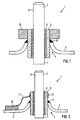
- FIG. 2 shows a second exemplary embodiment of an electrical feedthrough shown with a sacrificial electrode.
- the basic structure of the Implementation 1 according to FIG. 2 corresponds to the representation in FIG. 1 electrical conductor 2 extends through a sleeve 5. Between the sleeve 5 and the electrical conductor 2, an insulation 9 is formed.
- the sleeve 5 is formed in a through opening 4 of the jacket 3. The sleeve is welded to the jacket 3.
- the sacrificial electrode 10 On the jacket 3 of a housing of a catalytic converter is one Sacrificial electrode 10 arranged.
- the sacrificial electrode 10 cannot on one bolt shown, which is connected to the jacket 3 placed be.
- the sacrificial electrode 10 is via an electrical line 11, which preferably consists of copper, connected to the sleeve 5.
- an electrical line 11 which preferably consists of copper
- the cuff 12 is connected to the electrical line 11.
- FIG. 2 has the advantage that an exchange the sacrificial electrode 10 can be done relatively easily. Furthermore, a Visual inspection of the electrode 10 can be carried out without great effort.
- the bushing 1 has a protective device in the form of an end face 13 and the outer jacket of the sleeve 5 does not cover electrically conductive protective layer 14.
- the protective layer 14 extends to Jacket 3, whereby the sleeve 5 in connection with the insulation 9 of the electrical conductor 2 is decoupled from the outside.
- the protective layer 14 is formed in one layer. It is also possible, the protective layer 14, if this seems appropriate, multilayer to train. A multilayer protective layer can then be of interest if there is a different thermal expansion behavior of the sleeve 5, of the jacket 3 is present, so that no thermal in the protective layer 14 conditioned stress cracks arise.
- the protective layer is preferred non-porous, so that an accumulation of water on the protective layer 14 is avoided.
- Fig. 4 is a known implementation by a for comparison Ground potential housing shown.
- an electrical conductor 2 is through passed a metallic jacket 3 of a catalytic converter.
- the jacket 3 has a through opening 4 through which a sleeve 5 extends extends to.
- the sleeve 5 consists of a metallic material.
- Within the sleeve 5 is a electrical insulation 9 is provided which surrounds the conductor 2.
- a protective device is to prevent electrical corrosion on the bushing 15 provided that the jacket 3 and thus the sleeve 5 through an electrical connection to the jacket 3 and thus the sleeve to ground potential puts.
- the protective device 15 has a connection 16, which is extends through an opening 17 in the jacket 3.
- the connection 16 is welded to the jacket 3 at position 18.
- the connection 16 and the conductor 2 are made of the same metallic material.
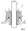
- FIG. 5 is a fifth embodiment of an electrically insulating Implementation 1 of an electrical conductor 2 through a metallic jacket 3 of an exhaust system of an internal combustion engine, in particular one electrically heated catalytic converter shown.
- a through opening 4 is formed through which a sleeve 5 extends through.
- the metallic sleeve 5 is along with the jacket 3 the weld 6 is welded.
- the conductor extends through the sleeve 5 2, the end of the conductor 2 protruding into the jacket 3 in the electrical Contact with a catalytic converter, not shown.
- the end 8 of the conductor 2 protruding from the sleeve 5 from the jacket 3 serves for electrical coupling to an electrical line 29, which with a voltage source, not shown, is connected.
- the coupling of the Conductor 2 to the electrical line 29 takes place by means of a contact body 27. In the exemplary embodiment shown, the electrical line 29 projects into the contact body 27.
- the contact body 27 For mechanical and electrical coupling of the contact body 27 the conductor 2, the contact body 27 has a blind hole 30.
- the Bore 30 and the conductor 2 each have a circular cross section on.
- the connection between the contact body 27 and the electrical Conductor 2 is made by means of a press fit, for which the bore 30 correspondingly has a smaller diameter than the conductor 2.
- An anodic protective layer 28 is provided on the contact body 27.
- the protective layer is preferably made of zinc.
- the sacrificial electrode 10 is arranged on the contact body 27. The positioning shown in FIG. 7 the sacrificial electrode 10 on the contact body 27 is exemplary and can be varied accordingly, always ensuring that the sacrificial electrode remains functional as such.
- FIG. 6 A further embodiment is shown in FIG. 6.
- this embodiment is the sacrificial electrode 10 directly on the electrical Line 29 arranged, which is connected to the contact body 27.
- the Connection of the sacrificial electrode 10 to the electrical line 29 can by the sacrificial electrode 10 on the electrical line 29 is puffed up.
- the sacrificial anode can also be opened directly if necessary be attached to the conductor or its end 8, insofar as this is not complete are covered by the contact body 27.
Description
Die vorliegende Erfindung betrifft eine elektrisch isolierende Durchführung wenigstens eines elektrischen Leiters durch einen metallischen Mantel eines Abgassystems einer Verbrennungskraftmaschine, insbesondere eines elektrisch beheizbaren katalytischen Konverters.The present invention relates to an electrically insulating bushing at least one electrical conductor through a metallic sheath Exhaust system of an internal combustion engine, in particular an electric one heatable catalytic converter.
Luftverschmutzung bedingt durch Autoabgase steht im Mittelpunkt des umweltpolitischen Interesses. Es besteht die Absicht der europäischen Kommission, bis September 1995 den Entwurf für eine weitere Stufe der Abgasgesetzgebung vorzulegen, die dann ab dem Jahre 2000 für Neuwagen gilt. Durch diese Vorschriften soll der Ausstoß an Schadstoffen aus Verbrennungsmotoren reduziert werden. Mit den steigenden Anforderungen an einer Verringerung der Schadstoffe in Abgasen aus Kraftfahrzeugen werden zunehmend komplexere Abgasreinigungssysteme für Verbrennungskraftmaschinen eingesetzt. Insbesondere zur Verringerung des Schadstoffausstosses während der Kaltstartphase eines Verbrennungsmotors werden neben geregelten Drei-Wege-Katalysatoren elektrisch beheizbare katalytische Konverter eingesetzt. Eine solche Anordnung ist z. B. durch die WO 92/02714 bekannt. Problematisch bei solchen elektrisch beheizbaren katalytischen Konvertern ist die elektrische Durchführung elektrischer Leiter von einer Spannungsquelle zu dem elektrisch beheizbaren katalytischen Konverter. Ein Lösungsvorschlag für eine elektrische Durchführung ist durch die WO 94/18442 bekannt. Air pollution caused by car emissions is the focus of the environmental interest. The European Commission intends to: by September 1995 the draft for a further stage of exhaust gas legislation to submit, which then from 2000 for new cars applies. These regulations are designed to emit pollutants from internal combustion engines be reduced. With the increasing demands on a reduction in pollutants in exhaust gases from motor vehicles increasingly complex exhaust gas purification systems for internal combustion engines used. In particular to reduce pollutant emissions during the cold start phase of an internal combustion engine are controlled in addition Three-way catalytic converters electrically heated catalytic converters used. Such an arrangement is e.g. B. known from WO 92/02714. Problematic with such electrically heatable catalytic converters is the electrical passage of electrical conductors from a voltage source to the electrically heated catalytic converter. A Proposed solution for an electrical implementation is through WO 94/18442 known.
Durch die EP-A-0 490 222 ist eine elektrisch isolierende Durchführung eines elektrischen Leiters durch einen metallischen Mantel eines Abgassystems einer Verbrennungskraftmaschine, insbesondere eines elektrisch beheizbaren katalytischen Konverters, bekannt. Der Mantel weist im Bereich der Durchführung eine Hülse aus einem metallischen Werkstoff auf. Die Hülse ist mit dem Mantel verbunden. Durch die Hülse erstreckt sich der elektrische Leiter. Der elektrische Leiter ist mit einer Spannungsquelle verbunden. EP-A-0 490 222 describes an electrically insulating feedthrough of an electrical Conductor through a metallic jacket of an exhaust system of an internal combustion engine, especially an electrically heatable catalytic Converter, known. The jacket has a in the area of the implementation Sleeve made of a metallic material. The sleeve is with the coat connected. The electrical conductor extends through the sleeve. Of the electrical conductor is connected to a voltage source.
Es ist festgestellt worden, daß die elektrische Durchführung und/oder elektrische Leiter durch Korrosion zerstört werden können.It has been found that the electrical implementation and / or electrical Conductors can be destroyed by corrosion.
Der vorliegenden Erfindung liegt die Aufgabe zugrunde, die gattungsbildende elektrisch isolierende Durchführung so weiter zu entwickeln, daß diese korrosionsbeständiger wird.The present invention has for its object the generic to develop electrically insulating implementation so that this becomes more corrosion resistant.
Diese Aufgabe wird erfindungsgemäß durch eine elektrisch isolierende
Durchführung mit den Merkmalen des Anspruchs 1, 11 oder 19 gelöst. Vorteilhafte
Weiterbildungen sind Gegenstand der Unteransprüche.This object is achieved by an electrically insulating
Implemented with the features of
Die erfindungsgemäße elektrisch isolierende Durchführung wenigstens eines elektrischen Leiters durch einen metallischen Mantel eines Abgassystems einer Verbrennungskraftmaschine, insbesondere eines elektrisch beheizbaren Konverters, wobei der Mantel im Bereich der Durchführung eine Hülse aus einem metallischen Werkstoff aufweist, die mit dem Mantel verbunden ist und durch die sich der Leiter erstreckt, zeichnet sich dadurch aus, daß die Durchführung eine Schutzeinrichtung aufweist, durch die Elektrokorrosion der Durchführung vermieden wird. Die Schutzeinrichtung umfaßt wenigstens eine Opferelektrode, die mit der Hülse elektrisch verbunden ist. Der Erfindung liegt der Gedanke zugrunde, daß die Korrosion der Durchführung im wesentlichen durch die Ausbildung galvanischer Elemente im Bereich der Durchführung bedingt ist. Aufgrund der verschiedenen metallischen Werkstoffe in der Durchführung, wobei einzelne Bauteile auf unterschiedlichen elektrischen Potentialen liegen, entstehen galvanische Elemente, wenn ein Elektrolyt hinzukommt. Bei einem Elektrolyten kann es sich um Wasser, insbesondere Salzwasser handeln. Um der durch die Ausbildung galvanischer Elemente bedingten Elektrokorrosion Einhalt zu gebieten, ist die Durchführung mit einer Schutzeinrichtung versehen. The electrically insulating bushing according to the invention has at least one electrical conductor through a metallic jacket of an exhaust system an internal combustion engine, in particular an electrically heatable Converter, the jacket in the area of the implementation of a sleeve has a metallic material which is connected to the jacket and through which the conductor extends is characterized in that the Implementation has a protective device by the electrical corrosion of the Implementation is avoided. The protective device comprises at least one sacrificial electrode which is electrically connected to the sleeve connected is. The invention is based on the idea that the corrosion is essentially due to training galvanic elements in the area of implementation is conditional. Because of of the various metallic materials in the implementation, whereby individual components are at different electrical potentials galvanic elements when an electrolyte is added. At a Electrolytes can be water, especially salt water. Around the electrical corrosion caused by the formation of galvanic elements To prevent this, the implementation is equipped with a protective device.
Die Ausbildung galvanischer Elemente wird zwar nicht verhindert, eine Elektrokorrosion wird jedoch von den Bauteilen der Durchführung auf die Opferelektrode hin verlagert. Hierdurch wird eine Korrosion der Durchführung verringert.The formation of galvanic elements is not prevents electrical corrosion from Components of the bushing are moved to the sacrificial electrode. Hereby corrosion of the bushing is reduced.
Bevorzugt ist eine Ausführungsform der Schutzeinrichtung, bei der die Opferelektrode auf der Hülse angeordnet ist. Die Opferelektrode ist dabei ringförmig ausgebildet und kraft- und/oder formschlüssig mit der Hülse verbunden. Durch die Verbindung der Opferelektrode mit der Hülse kann die Opferelektrode bei Bedarf ausgetauscht werden. Die Anbringung der Opferelektrode auf der Hülse hat auch den Vorteil, daß die Opferelektrode einer Sichtprüfung unterzogen werden kann, ohne daß umfangreiche Demontagearbeiten notwendig sind. Zur kraftschlüssigen Verbindung der Opferelektrode mit der Hülse wird vorgeschlagen, die Opferelektrode auf die Hülse zu pressen oder warm aufzuschrumpfen.An embodiment is preferred the protective device with the sacrificial electrode on the Sleeve is arranged. The sacrificial electrode is ring-shaped and non-positively and / or positively connected to the sleeve. Through the Connection of the sacrificial electrode to the sleeve can help the sacrificial electrode Need to be exchanged. The attachment of the sacrificial electrode on the Sleeve also has the advantage that the sacrificial electrode is a visual inspection can be subjected without extensive dismantling work being necessary are. For the non-positive connection of the sacrificial electrode with the sleeve it is suggested to press the sacrificial electrode onto the sleeve or warm shrink.
Gemäß eines weiteren vorteilhaften Gedankens wird vorgeschlagen, die Opferelektrode auf dem Mantel anzuordnen und elektrisch mit der Hülse zu verbinden. Die Verbindung der Opferelektrode mit dem Mantel ist vorzugsweise lösbar ausgebildet. Hierzu wird vorgeschlagen, die Opferelektrode auf einem mit dem Mantel festverbundenen Bolzen anzuordnen. Durch diese Ausbildung wird der Ersatz der Opferelektrode vereinfacht. Ferner wird die Möglichkeit geboten, mehrere Opferelektroden auf dem Mantel anzuordnen, so daß eine räumliche Begrenzung der Opferelektrode, wie dies bei einer Anordnung der Opferelektrode auf der Hülse der Fall sein kann, vermieden wird. Die Verbindung der Opferelektrode mit der Hülse erfolgt vorzugsweise mittels einer Leitung aus einem elektrisch gut leitenden Werkstoff, insbesondere mittels einer Kupferleitung. According to a further advantageous idea, it is proposed that Arrange sacrificial electrode on the jacket and electrically with the sleeve connect. The connection of the sacrificial electrode to the jacket is preferred designed to be detachable. For this purpose, it is proposed to put the sacrificial electrode on to arrange a bolt firmly connected to the jacket. Through this Training, the replacement of the sacrificial electrode is simplified. Furthermore, the Offered the possibility of placing several sacrificial electrodes on the jacket, so that a spatial limitation of the sacrificial electrode, as in a Arrangement of the sacrificial electrode on the sleeve may be avoided becomes. The sacrificial electrode is preferably connected to the sleeve by means of a line made of an electrically highly conductive material, in particular by means of a copper line.
Der Leiter der Durchführung wird über eine elektrische Leitung mit einer Spannungsquelle verbunden. Zur Verbindung der elektrischen Leitung mit dem Leiter werden Kontaktkörper verwendet. Es wird vorgeschlagen am Kontaktkörper die Opferelektrode auszubilden. Diese Ausbildung hat den Vorteil, daß der bisherige Herstellungsprozeß eines elektrisch beheizbaren katalytischen Konverters beibehalten werden kann. Um einen sicheren Kontakt zwischen dem Leiter und dem Kontaktkörper herzustellen, wird vorgeschlagen, den Leiter mit dem Kontaktkörper kraft- und/oder formschlüssig verbindbar auszubilden.The head of the implementation is connected to an electrical line Power source connected. To connect the electrical line with contact bodies are used for the conductor. It is proposed on Contact body to form the sacrificial electrode. This training has the Advantage that the previous manufacturing process of an electrically heated catalytic converter can be maintained. For a safe contact between the conductor and the contact body, it is proposed the conductor with the contact body non-positively and / or positively trainable.
Gemäß einem weiteren Vorschlag ist der Kontaktkörper mit einer Schutzschicht versehen, die direkt auf dem Kontaktkörper aufgebracht ist. Die Schutzschicht kann beispielsweise aus Zink bestehen. Sie wirkt anodisch.According to a further proposal, the contact body is with a Provide protective layer that is applied directly to the contact body. The protective layer can consist of zinc, for example. It has an anodic effect.
Neben den vorstehend beschriebenen Alternativen der Anordnung einer Opferelektrode kann diese auch unmittelbar auf einer elektrischen Leitung, die einesends mit dem Leiter und anderenends mit einer Spannungsquelle verbunden ist, angeordnet sein. Die Opferelektrode kann dabei beispielsweise auf der elektrischen Leitung aufgequetscht sein.In addition to the alternatives described above, the arrangement of a Sacrificial electrode can also be directly on an electrical line, one with the conductor and the other with a voltage source is connected to be arranged. The sacrificial electrode can, for example be squeezed on the electrical wire.
Gemäß einem weiteren vorteilhaften Gedanken wird vorgeschlagen, die Opferelektrode aus einem Werkstoff herzustellen, der gegenüber dem Werkstoff des Leiters und der Hülse in der Spannungsreihe der Metalle unedler ist. Vorzugsweise besteht die Elektrode aus Zink. Zink hat in der Spannungsreihe ein Normalpotential von -0,76 V. Eine Elektrode aus Nickel hat ein Normalpotential von -0,24 V. Beide Opferelektroden bilden den Negativpol des galvanischen Elementes.According to a further advantageous idea, the Produce sacrificial electrode from a material that is compared to the material of the conductor and the sleeve in the voltage series of the metals less noble is. The electrode is preferably made of zinc. Zinc has in the voltage series has a normal potential of -0.76 V. An electrode made of nickel a normal potential of -0.24 V. Both sacrificial electrodes form the negative pole of the galvanic element.
Gemäß einem weiteren erfinderischen Gedanken wird vorgeschlagen, die
Durchführung mit einer eine Elektrokorrosion der Durchführung
vermeidenden Schutzeinrichtung zu versehen, durch die eine
Wegstrecke für einen elektrischen Strom eines sich bildenden galvanischen
Elementes sich verlängert. Dadurch, daß der elektrische Widerstand unter
anderem auch davon abhängt, wie lang die elektrische Führung ist, wird
durch die Verlängerung des Stromweges ein Widerstand erzielt, durch den
ein Stromfluß und die daraus resultierende Elektrokorrosion verringert. Die
Verlängerung der Wegstrecke für einen elektrischen Strom ist insbesondere
im Zusammenhang mit elektrischbeheizbaren katalytischen Konvertern von
Interesse, die bei höheren Spannungen betrieben werden. Beispielsweise kann
ein solcher elektrisch beheizbarer katalytischer Konverter mit einer Spannung
ca. 30 Volt betrieben werden. Zur konkreteren Ausgestaltung der Schutzeinrichtung
wird vorgeschlagen, daß die Schutzeinrichtung durch eine wenigstens
die aus dem Mantel ragende Stirnfläche der Hülse abdeckende elektrisch
nicht leitende wenigstens eine Lage aufweisende Schutzschicht gebildet wird.
Vorzugsweise besteht die Schutzschicht oder die äußere Lage der Schutzschicht
aus einem hydrophoben Werkstoff. Hierdurch wird vermieden, daß
auf der Schutzschicht Elektrolytansammlungen in Form von Wasser sich
bilden, die erst das Entstehen einer Elektrokorrosion bedingen.According to a further inventive idea, the
Implementation with an electrical corrosion of the implementation
preventive protective device, through which one
Path for an electrical current of a galvanic
Element is extended. The fact that the electrical resistance under
also depends on how long the electrical guide is
achieved a resistance by extending the current path through which
a current flow and the resulting electrical corrosion is reduced. The
Extending the distance for an electric current is particularly important
in connection with electrically heated catalytic converters from
Interest that operate at higher voltages. For example
such an electrically heated catalytic converter with a
Gemäß eines weiteren vorteilhaften Gedankens wird vorgeschlagen, die Schutzschicht aus wenigstens einer Lage eines Kunststoffes auszubilden, vorzugsweise aus Silikon. Alternativ zu Silikon kann die Schutzschicht aus Glas bestehen. Die Schutzschicht sollte generell aus einem Werkstoff bestehen, der porenfrei ist.According to a further advantageous idea, it is proposed that To form a protective layer from at least one layer of plastic, preferably made of silicone. As an alternative to silicone, the protective layer can be made of Glass exist. The protective layer should generally consist of a material that is non-porous.
Gemäß einem weiteren erfinderischen Gedanken wird eine Durchführung vorgeschlagen, bei der eine Elektrokorrosion dadurch vermieden wird, daß die Schutzeinrichtung durch eine elektrische Verbindung des Mantels mit Massepotential gebildet wird. Hierdurch wird ein Potentialaufbau im Bereich des elektrischen Minuspols der elektrischen Durchführung verhindert, wodurch der Effekt der Elektrokorrosion wirksam verhindert wird. According to a further inventive idea, an implementation proposed in which an electrical corrosion is avoided in that the protective device with an electrical connection of the jacket Ground potential is formed. This creates a potential in the area of the electrical negative pole of the electrical feedthrough prevented, whereby the effect of electrical corrosion is effectively prevented.
Weitere Vorteile und Einzelheiten der erfindungsgemäßen elektrisch isolierenden Durchführung werden anhand der in der Zeichnung bevorzugten Ausführungsbeispiele erläutert. Es zeigen:
- Fig. 1
- im Schnitt ein erstes Ausführungsbeispiel einer Durchführung mit einer Opferelektrode,
- Fig. 2
- im Schnitt ein zweites Ausführungsbeispiel einer Durchführung mit einer Opferelektrode,
- Fig. 3
- im Schnitt ein drittes Ausführungsbeispiel einer elektrischen Durchführung mit einer Schutzschicht,
- Fig. 4
- im Schnitt ein Beispiel einer Durchführung gemäß dem Stand der Technik mit Anschluß des Gehäuses an Masse potential,
- Fig. 5
- im Schnitt ein fünftes Ausführungsbeispiel einer Durchführung mit einem Gehäuse und
- Fig. 6
- im Schnitt ein sechstes Ausführungsbeispiel einer Durchführung mit einem Gehäuse.
- Fig. 1
- in section a first embodiment of a bushing with a sacrificial electrode,
- Fig. 2
- in section a second embodiment of a bushing with a sacrificial electrode,
- Fig. 3
- on average a third exemplary embodiment of an electrical feedthrough with a protective layer,
- Fig. 4
- on average an example of a implementation according to the prior art with connection of the housing to ground potential,
- Fig. 5
- on average a fifth embodiment of a bushing with a housing and
- Fig. 6
- in section, a sixth embodiment of a bushing with a housing.
In der Fig. 1 ist ein erstes Ausführungsbeispiel einer elektrisch isolierenden
Durchführung 1 eines elektrischen Leiters 2 durch einen metallischen Mantel
3 eines Abgassystems einer Verbrennungskraftmaschine, insbesondere eines
elektrisch beheizbaren katalytischen Konverters dargestellt. Der Aufbau eines
solchen katalytischen Konverters ist beispielsweise in der WO 92/02714
beschrieben.1 is a first embodiment of an electrically insulating
Implementation 1 of an
In dem Mantel 3 ist eine Durchgangsöffnung 4 ausgebildet, durch welche
sich eine Hülse 5 hindurcherstreckt. Die metallische Hülse 5 ist mit dem
Mantel 3 verschweißt. Mit 6 ist die Schweißnaht zwischen der Hülse 5 und
dem Mantel 3 bezeichnet. Durch die Hülse 5 erstreckt sich der Leiter 2.
Das in den Mantel 3 hineinragende Ende 7 des Leiters 2 steht in elektrischem
Kontakt mit einem nicht dargestellten katalytischen Konverter. Das
aus der Hülse 5 vom Mantel 3 wegragende Ende 8 des Leiters 2 dient zu
elektrischen Ankopplung an einen elektrischen Leiter, welcher nicht dargestellt
ist, der mit einer Spannungsquelle verbunden ist.A through opening 4 is formed in the
Zwischen dem Leiter 2 und der Hülse 5 ist eine elektrische Isolierung 9
angebracht, so daß eine elektrische Entkopplung zwischen der Hülse 5 und
dem Leiter 2 gewährleistet ist. Bei der Isolierung 9 kann es sich beispielsweise
um Aluminiumoxid handeln.
Wie aus der Fig. 1 ersichtlich ist, ragt die Hülse 5 aus dem Mantel 3 nach
außen heraus. An diesem vorstehenden Endbereich der Hülse 5 ist eine
Opferelektrode 10 angebracht. Die Opferelektrode 10 ist kraftschlüssig mit
der Hülse 5 verbunden. Die Opferelektrode 10 ist ringförmig ausgebildet. As can be seen from FIG. 1, the
Die Innen- und Außenkonturen der Opferelektrode 10 kann an die baulichen
Gegebenheiten z. B. der Hülse 5 angepaßt sein.The inner and outer contours of the
Die Opferelektrode 10 besteht vorzugsweise aus Zink. Sammelt sich ein
Elektrolyt z. B. in der Form von Salzwasser oberhalb der Hülse 5 und es
kommt zu einem Kontakt zwischen dem Leiter 2 und der Hülse 5, so fließt
ein elektrischer Strom über die Opferelektrode 10, wodurch die Opferelektrode
10 korrodiert. Hierdurch wird vermieden, daß die Hülse 5 bzw. der
Leiter 2 korrodiert.The
In der Fig. 2 ist ein zweites Ausführungsbeispiel einer elektrischen Durchführung
mit einer Opferelektrode dargestellt. Der prinzipielle Aufbau der
Durchführung 1 nach Fig. 2 entspricht der Darstellung in der Fig. 1. Der
elektrische Leiter 2 erstreckt sich durch eine Hülse 5. Zwischen der Hülse
5 und dem elektrischen Leiter 2 ist eine Isolierung 9 ausgebildet. Die Hülse
5 ist in einer Durchgangsöffnung 4 des Mantels 3 ausgebildet. Die Hülse ist
mit dem Mantel 3 verschweißt.2 shows a second exemplary embodiment of an electrical feedthrough
shown with a sacrificial electrode. The basic structure of the
Implementation 1 according to FIG. 2 corresponds to the representation in FIG. 1
Auf dem Mantel 3 eines Gehäuses eines katalytischen Konverters ist eine
Opferelektrode 10 angeordnet. Die Opferelektrode 10 kann auf einem nicht
weiter dargestellten Bolzen, der mit dem Mantel 3 verbunden ist aufgesetzt
sein. Die Opferelektrode 10 ist über eine elektrische Leitung 11, welche
vorzugsweise aus Kupfer besteht, mit der Hülse 5 verbunden. In dem in der
Fig. 2 dargestellten Ausführungsbeispiel ist auf der Hülse 5 eine Manschette
12, die aus einem elektrisch gut leitendem Werkstoff besteht, angeordnet.
Die Manschette 12 ist mit der elektrischen Leitung 11 verbunden. Die in
der Fig. 2 dargestellte Ausführungsform hat den Vorteil, daß ein Austausch
der Opferelektrode 10 relativ einfach erfolgen kann. Ferner kann eine
Sichtprüfung der Elektrode 10 ohne großen Aufwand erfolgen. On the
In der Fig. 3 ist ein drittes Ausführungsbeispiel einer erfindungsgemäßen
elektrisch isolierenden Durchführung eines elektrischen Leiters 2 durch einen
metallischen Mantel 3 eines Abgassystems einer Verbrennungskraftmaschine
dargestellt. Der Mantel 3 weist im Bereich der Durchführung 1 eine Durchgangsöffnung
4 durch die sich eine Hülse 5 hindurcherstreckt, auf. Die
Hülse 5 ist mit dem Mantel 3 mittels einer Schweißnaht 6 verschweißt.3 is a third embodiment of an inventive
electrically insulating passage of an
Zwischen der Hülse 5 und dem elektrischen Leiter 2 ist eine elektrische
Isolierung 9 ausgebildet, die den Leiter 2 von der Hülse 5 und somit dem
Mantel 3 elektrisch entkoppelt.Between the
Die Durchführung 1 weist eine Schutzeinrichtung in Form einer die Stirnfläche
13 und den Außenmantel der Hülse 5 abdeckenden elektrisch nicht
leitenden Schutzschicht 14. Die Schutzschicht 14 erstreckt sich bis zum
Mantel 3, wodurch die Hülse 5 in Verbindung mit der Isolierung 9 von
dem elektrischen Leiter 2 von außen her entkoppelt ist. In dem dargestellten
Ausführungsbeispiel ist die Schutzschicht 14 einlagig ausgebildet. Es ist auch
möglich, die Schutzschicht 14, wenn dies zweckmäßig erscheint, mehrlagig
auszubilden. Eine mehrlagige Schutzschicht kann dann von Interesse sein,
wenn ein unterschiedliches thermisches Ausdehnungsverhalten der Hülse 5,
des Mantels 3 vorhanden ist, so daß in der Schutzschicht 14 keine thermisch
bedingten Spannungsrisse entstehen. Die Schutzschicht ist vorzugsweise
porenfrei, so daß eine Ansammlung von Wasser auf der Schutzschicht 14
vermieden wird.The bushing 1 has a protective device in the form of an
In der Fig. 4 ist zum Vergleich eine an sich bekannte Durchführung durch ein an
Masse potential liegendes Gehäuse dargestellt.
In der Durchführung 1 wird ein elektrischer Leiter 2 durch
einen metallischen Mantel 3 eines katalytischen Konverters hindurchgeführt.
Der Mantel 3 weist eine Durchgangsöffnung 4 durch die sich eine Hülse 5
erstreckt auf. Die Hülse 5 besteht aus einem metallischen Werkstoff. Der
Mantel 3 ist mit der Hülse 5 verschweißt. Innerhalb der Hülse 5 ist eine
elektrische Isolierung 9 vorgesehen, welche den Leiter 2 umgibt.In Fig. 4 is a known implementation by a for comparison
Ground potential housing shown.
In the implementation 1, an
Zur Vermeidung einer Elektrokorrosion an der Durchführung ist eine Schutzeinrichtung
15 vorgesehen, die den Mantel 3 und somit die Hülse 5 durch
eine elektrische Verbindung den Mantel 3 und somit die Hülse auf Massepotential
setzt. Die Schutzeinrichtung 15 weist einen Anschluß 16 auf, der sich
durch eine Öffnung 17 im Mantel 3 hindurcherstreckt. Der Anschluß 16 ist
mit dem Mantel 3 an der Position 18 verschweißt. Der Anschluß 16 und
der Leiter 2 bestehen aus gleichem metallischen Werkstoff. A protective device is to prevent electrical corrosion on the
In der Fig. 5 ist ein fünftes Ausführungsbeispiel einer elektrisch isolierenden
Durchführung 1 eines elektrischen Leiters 2 durch einen metallischen Mantel
3 eines Abgassystems einer Verbrennungskraftmaschine, insbesondere eines
elektrisch beheizbaren katalytischen Konverters dargestellt. In dem Mantel 3
ist eine Durchgangsöffnung 4 ausgebildet, durch die sich eine Hülse 5
hindurch erstreckt. Die metallische Hülse 5 ist mit dem Mantel 3 entlang
der Schweißnaht 6 verschweißt. Durch die Hülse 5 erstreckt sich der Leiter
2, wobei das in den Mantel 3 hineinragende Ende des Leiters 2 im elektrischen
Kontakt mit einem nicht dargestellten katalytischen Konverters steht.
Das aus der Hülse 5 vom Mantel 3 wegragende Ende 8 des Leiters 2 dient
zur elektrischen Ankopplung an eine elektrische Leitung 29, die mit einer
nicht dargestellten Spannungsquelle verbunden ist. Die Ankopplung des
Leiters 2 an die elektrische Leitung 29 erfolgt mittels eines Kontaktkörpers
27. In dem dargestellten Ausführungsbeispiel ragt die elektrische Leitung 29
in den Kontaktkörper 27 hinein.5 is a fifth embodiment of an electrically insulating
Implementation 1 of an
Zur mechanischen und elektrischen Ankopplung des Kontaktkörpers 27 an
den Leiter 2 weist der Kontaktkörper 27 einen Sacklochbohrung 30 auf. Die
Bohrung 30 und der Leiter 2 weisen jeweils einen kreisförmigen Querschnitt
auf. Die Verbindung zwischen dem Kontaktkörper 27 und dem elektrischen
Leiter 2 erfolgt mittels eines Press-Sitzes, wofür die Bohrung 30 entsprechend
einen geringeren Durchmesser aufweist als der Leiter 2.For mechanical and electrical coupling of the
Auf dem Kontaktkörper 27 ist eine anodische Schutzschicht 28 vorgesehen.
Die Schutzschicht besteht vorzugsweise aus Zink. An dem Kontaktkörper 27
ist die Opferelektrode 10 angeordnet. Die in der Fig. 7 dargestellte Positionierung
der Opferelektrode 10 auf dem Kontaktkörper 27 ist beispielhaft und
kann entsprechend variiert werden, wobei stets sichergestellt werden soll,
daß die Opferelektrode auch als solche funktionsfähig bleibt.An anodic
In der Fig. 6 ist eine weitere Ausführungsform dargestellt. In dieser Ausführungsform
ist die Opfereleketrode 10 unmittelbar an der elektrischen
Leitung 29 angeordnet, die mit dem Kontaktkörper 27 verbunden ist. Die
Verbindung der Opferelektrode 10 mit der elektrischen Leitung 29 kann
dadurch erfolgen, daß die Opferelektrode 10 auf der elektrischen Leitung 29
aufgequescht ist. Natürlich kann bei Bedarf auch die Opferanode direkt auf
dem Leiter oder dessen Ende 8 angebracht sein, soweit diese nicht vollständig
von dem Kontaktkörper 27 abgedeckt sind. A further embodiment is shown in FIG. 6. In this embodiment
is the
- 11
- Durchführungexecution
- 22nd
- Leiterladder
- 33rd
- Mantelcoat
- 44th
- DurchgangsöffnungThrough opening
- 55
- HülseSleeve
- 66
- SchweißnahtWeld
- 7, 87, 8
- EndeThe End
- 99
- Isolierunginsulation
- 1010th
- OpferelektrodeSacrificial electrode
- 1111
- Leitungmanagement
- 1212th
- Manschettecuff
- 1313
- StirnflächeFace
- 1414
- SchutzschichtProtective layer
- 1515
- SchutzeinrichtungProtective device
- 1616
- AnschlußConnection
- 1717th
- Öffnungopening
- 1818th
- SchweißnahtWeld
- 2727
- KontaktkörperContact body
- 2828
- Schutzschicht Protective layer
- 2929
- elektrische Leitungelectrical line
- 3030th
- SacklochzahnungBlind toothing
Claims (19)
- An electrically insulating lead-through assembly (1) for at least one electric conductor (2) through a metal casing (3) of an exhaust gas system of an internal combustion engine, in particular an electrically heatable catalytic converter, wherein in the region of the lead-through assembly (1) the casing (3) has a sleeve (5) which comprises a metal material and which is connected to the casing (3) and through which the conductor (2) extends. characterised in that the lead-through assembly (1) has a protection means (15) which avoids electrocorrosion of the lead-through assembly (1) and which includes at least one sacrificial electrode (10) which is electrically connected to the sleeve (5)
- A lead-through assembly according to claim 1 characterised in that the sacrificial electrode (10) is arranged on the sleeve (5).
- A lead-through assembly according to claim 2 characterised in that the sacrificial electrode (10) is of an annular configuration.
- A lead-through assembly according to claim 3 characterised in that the sacrificial electrode (10) is force-lockingly and/or positively lockingly connected to the sleeve (5).
- A lead-through assembly according to claim 1 characterised in that the sacrificial electrode (10) is arranged on the casing (3) and is electrically connected to the sleeve (5).
- A lead-through assembly according to claim 5 characterised in that the sacrificial electrode (10) is releasably connected to the casing (3).
- A lead-through assembly according to claim 5 characterised in that the sacrificial electrode (10) is arranged on a bolt or pin fixedly connected to the casing (3).
- A lead-through assembly according to claim 5, claim 6 or claim 7 characterised in that the electrical connection between the sacrificial electrode (10) and the casing (3) is formed by a lead of a material which is a good electrical conductor, in particular copper.
- A lead-through assembly according to one of claims 1 through 8 characterised in that the sacrificial electrode (10) comprises a material which is baser in the electromotive series than the material of the conductor (2).
- A lead-through assembly according to claim 9 characterised in that the sacrificial electrode (10) comprises zinc.
- An electrically insulating lead-through assembly (1) for at least one electric conductor (2) through a metal casing (3) of an exhaust gas system of an internal combustion engine, in particular an electrically heatable catalytic converter, wherein in the region of the lead-through assembly (1) the casing (3) has a sleeve (5) which comprises a metal material and which is connected to the casing (3) and through which the conductor (2) extends, characterised in that the lead-through assembly (1) has a protection means (15) which avoids electrocorrosion of the lead-through assembly (1) and by which a path for an electric current of a galvanic element which is formed is increased in length.
- A lead-through assembly according to claim 1 or claim 11 characterised in that the protection means (15) is formed by an electrically non-conducting protection layer (14) which has at least one layer portion and which covers at least the end surface (13) of the sleeve (5), which projects out of the casing.
- A lead-through assembly according to claim 12 characterised in that the protection layer (14) or the outer layer portion thereof is pore-free.
- A lead-through assembly according to claim 12 or claim 13 characterised in that the protection layer (14) or the outer layer portion of the protection layer (14) comprises a hydrophobic material.
- A lead-through assembly according to claim 12, claim 13 or claim 14 characterised in that the protection layer (14) has at least one layer portion of a plastics material, preferably silicone.
- A lead-through assembly according to one of claims 12 through 14 characterised in that the protection layer (14) has at least one layer portion of glass.
- A lead-through assembly according to one of claims 12 through 16 characterised in that the protection layer (14) completely encloses the outside surface of the sleeve (5).
- A lead-through assembly according to claim 17 characterised in that the protection layer (14) is at least partially formed on the casing (3).
- A lead-through assembly according to one of the claims 11 through 18 characterised in that the casing (3) has an electrical connection to ground potential.
Applications Claiming Priority (3)
| Application Number | Priority Date | Filing Date | Title |
|---|---|---|---|
| DE19533088A DE19533088A1 (en) | 1995-09-07 | 1995-09-07 | Electrical insulating bushing with an electrical corrosion protection device |
| DE19533088 | 1995-09-07 | ||
| PCT/EP1996/003809 WO1997009519A1 (en) | 1995-09-07 | 1996-08-29 | Electrical insulation lead-through with a device protecting against the electrocorrosion |
Publications (2)
| Publication Number | Publication Date |
|---|---|
| EP0848785A1 EP0848785A1 (en) | 1998-06-24 |
| EP0848785B1 true EP0848785B1 (en) | 1999-05-19 |
Family
ID=7771526
Family Applications (1)
| Application Number | Title | Priority Date | Filing Date |
|---|---|---|---|
| EP96930982A Expired - Lifetime EP0848785B1 (en) | 1995-09-07 | 1996-08-29 | Electrical insulation lead-through with a device protecting against the electrocorrosion |
Country Status (9)
| Country | Link |
|---|---|
| US (1) | US6025578A (en) |
| EP (1) | EP0848785B1 (en) |
| JP (1) | JPH11512166A (en) |
| CN (1) | CN1081728C (en) |
| AU (1) | AU6985396A (en) |
| DE (2) | DE19533088A1 (en) |
| ES (1) | ES2134636T3 (en) |
| RU (1) | RU2151890C1 (en) |
| WO (1) | WO1997009519A1 (en) |
Cited By (4)
| Publication number | Priority date | Publication date | Assignee | Title |
|---|---|---|---|---|
| EP3819484B1 (en) * | 2019-11-05 | 2023-01-25 | Purem GmbH | Exhaust gas system for an internal combustion engine and method of manufacturing of an exhaust gas system |
| WO2023011926A1 (en) * | 2021-08-06 | 2023-02-09 | Vitesco Technologies GmbH | Segmented electrical feedthrough |
| DE202021105177U1 (en) | 2021-09-27 | 2023-03-29 | Hjs Emission Technology Gmbh & Co. Kg | Temperature-resistant electrical connection of an electrical consumer contained in a housing and an electrical heating unit equipped with it |
| DE102021124891A1 (en) | 2021-09-27 | 2023-03-30 | Hjs Emission Technology Gmbh & Co. Kg | Temperature-resistant electrical connection of an electrical consumer contained in a housing and an electrical heating unit equipped with it |
Families Citing this family (22)
| Publication number | Priority date | Publication date | Assignee | Title |
|---|---|---|---|---|
| DE10051562A1 (en) * | 2000-10-18 | 2002-04-25 | Emitec Emissionstechnologie | Electrically heated honeycomb body used for removing hydrocarbons or nitrogen oxides from I.C. engine exhaust gases comprises two zones with different coatings arranged behind each other in the flow direction |
| DE202005006046U1 (en) * | 2005-04-16 | 2005-07-07 | Heinrich Gillet Gmbh | exhaust system |
| US20110014825A1 (en) * | 2009-07-16 | 2011-01-20 | Delphi Technologies, Inc. | Electrical terminal connection with galvanic sacrificial metal |
| DE102010045507A1 (en) * | 2010-09-15 | 2012-03-15 | Emitec Gesellschaft Für Emissionstechnologie Mbh | Arrangement for a power supply of a component in an exhaust system |
| EP2591855B1 (en) * | 2010-11-11 | 2016-02-10 | Toyota Jidosha Kabushiki Kaisha | Electrically heated catalyst |
| CN102678232A (en) * | 2012-05-14 | 2012-09-19 | 无锡威孚力达催化净化器有限责任公司 | Electrode column component of device for burning carbon particles by electric energy heating |
| US11613814B2 (en) * | 2018-10-04 | 2023-03-28 | Sensus Spectrum, Llc | Sacrificial anodes for use in meters |
| DE102018217437A1 (en) * | 2018-10-11 | 2020-04-16 | Continental Automotive Gmbh | Exhaust gas treatment device |
| FR3091729B1 (en) * | 2019-01-10 | 2021-04-09 | Faurecia Systemes Dechappement | Exhaust gas heater, comprising an advanced power supply rod |
| DE102019121345A1 (en) * | 2019-08-07 | 2021-02-11 | Faurecia Emissions Control Technologies, Germany Gmbh | Heating device for preheating an exhaust gas flow and vehicle |
| DE102019212133B4 (en) * | 2019-08-13 | 2021-05-27 | Vitesco Technologies GmbH | Electrically heated catalytic converter |
| EP3967857A1 (en) | 2020-01-14 | 2022-03-16 | Hidria d.o.o. | Electrical connection |
| FR3108677B1 (en) * | 2020-03-30 | 2022-05-27 | Faurecia Systemes Dechappement | Exhaust gas heater, associated exhaust line and vehicle |
| DE102020206293A1 (en) | 2020-05-19 | 2021-11-25 | Vitesco Technologies GmbH | Electrical implementation |
| FR3115563B1 (en) * | 2020-10-27 | 2022-11-04 | Faurecia Systemes Dechappement | Heating device for a space-saving exhaust gas purification device |
| FR3118675B1 (en) * | 2021-01-04 | 2024-03-01 | Faurecia Systemes Dechappement | Electrical assembly for transporting electrical energy subjected to high temperature |
| DE102021110048A1 (en) * | 2021-04-21 | 2022-10-27 | Schott Ag | Feedthrough through a housing component, especially for harsh, mechanically and thermally stressed environments |
| DE102021113741B3 (en) | 2021-05-27 | 2022-10-06 | Benteler Automobiltechnik Gmbh | Exhaust gas treatment device for arrangement in an exhaust system of a motor vehicle |
| DE102021121835A1 (en) * | 2021-08-24 | 2023-03-02 | Purem GmbH | connection unit |
| DE102021211205A1 (en) | 2021-10-05 | 2023-04-06 | Vitesco Technologies GmbH | Electrical feedthrough and method of making same |
| US20230151749A1 (en) * | 2021-11-18 | 2023-05-18 | Faurecia Emissions Control Technologies, Usa, Llc | Exhaust aftertreatment system with electrical connector |
| DE102021213735B4 (en) | 2021-12-02 | 2023-11-16 | Vitesco Technologies GmbH | Electrical feedthrough with contact protection |
Family Cites Families (16)
| Publication number | Priority date | Publication date | Assignee | Title |
|---|---|---|---|---|
| US3116401A (en) * | 1960-06-22 | 1963-12-31 | Wiegand Co Edwin L | Electric heaters |
| US3176115A (en) * | 1963-05-20 | 1965-03-30 | Gen Electric | Electric water heater |
| US3838384A (en) * | 1971-09-07 | 1974-09-24 | Aluminum Co Of America | Protected electrode lead for use in a corrosive environment |
| US4152578A (en) * | 1977-10-03 | 1979-05-01 | Emerson Electric Co. | Electric heating elements |
| US4219857A (en) * | 1977-12-22 | 1980-08-26 | General Electric Company | Protective method and circuits for sheathed electrical resistance heating units |
| AT364202B (en) * | 1978-04-13 | 1981-10-12 | Thurner Anton Dipl Ing Dr | CORROSION PROTECTION FOR EXHAUST SYSTEMS |
| US4543469A (en) * | 1982-04-26 | 1985-09-24 | Emerson Electric Co. | Grounding arrangement for metal sheathed heating element having a plastic mounting member |
| JPS61110786A (en) * | 1984-11-02 | 1986-05-29 | Sanyo Electric Co Ltd | Electrode device for preventing corrosion |
| US4830724A (en) * | 1987-08-20 | 1989-05-16 | A. O. Smith Corporation | Stamped metal anode cap assembly |
| US5023928A (en) * | 1989-08-30 | 1991-06-11 | A. O. Smith Corporation | Apparatus for reducing the current drain on the sacrificial anode in a water heater |
| EP0541585B1 (en) * | 1990-07-30 | 1994-01-19 | Emitec Gesellschaft für Emissionstechnologie mbH | Electrically heated honeycomb body, in particular a catalytic converter body, with internal support structures |
| DE4129893A1 (en) * | 1991-09-09 | 1993-03-11 | Emitec Emissionstechnologie | ARRANGEMENT FOR MEASURING TEMPERATURE AND / OR HEATING AND USE THEREOF IN A HONEYCOMB BODY, IN PARTICULAR CATALYST CARRIER BODY |
| ES2073969B1 (en) * | 1992-11-06 | 1998-04-01 | Estevez Andres Herrera | SYSTEM FOR PROTECTION AGAINST CORROSION OF THE SMOKE EXHAUST PIPE AND THE ANTI-CONTAMINATION CATALYST OF INTERNAL COMBUSTION MOTOR VEHICLES. |
| US5335311A (en) * | 1993-01-19 | 1994-08-02 | Glengarry Industries Ltd. | Modular galvanic current control resistor assembly for mounting on an electric immersion heater |
| DE4303581A1 (en) * | 1993-02-08 | 1994-08-11 | Emitec Emissionstechnologie | Electrically insulating gas-tight passage of at least one electrical conductor through a metallic jacket |
| JP3078736B2 (en) * | 1994-12-07 | 2000-08-21 | 日本碍子株式会社 | Electrode structure and electric heating heater |
-
1995
- 1995-09-07 DE DE19533088A patent/DE19533088A1/en not_active Withdrawn
-
1996
- 1996-08-29 WO PCT/EP1996/003809 patent/WO1997009519A1/en active IP Right Grant
- 1996-08-29 DE DE59601955T patent/DE59601955D1/en not_active Expired - Fee Related
- 1996-08-29 CN CN96196802A patent/CN1081728C/en not_active Expired - Fee Related
- 1996-08-29 EP EP96930982A patent/EP0848785B1/en not_active Expired - Lifetime
- 1996-08-29 AU AU69853/96A patent/AU6985396A/en not_active Abandoned
- 1996-08-29 RU RU98106392/06A patent/RU2151890C1/en not_active IP Right Cessation
- 1996-08-29 ES ES96930982T patent/ES2134636T3/en not_active Expired - Lifetime
- 1996-08-29 JP JP9510838A patent/JPH11512166A/en active Pending
-
1998
- 1998-03-09 US US09/037,000 patent/US6025578A/en not_active Expired - Fee Related
Cited By (4)
| Publication number | Priority date | Publication date | Assignee | Title |
|---|---|---|---|---|
| EP3819484B1 (en) * | 2019-11-05 | 2023-01-25 | Purem GmbH | Exhaust gas system for an internal combustion engine and method of manufacturing of an exhaust gas system |
| WO2023011926A1 (en) * | 2021-08-06 | 2023-02-09 | Vitesco Technologies GmbH | Segmented electrical feedthrough |
| DE202021105177U1 (en) | 2021-09-27 | 2023-03-29 | Hjs Emission Technology Gmbh & Co. Kg | Temperature-resistant electrical connection of an electrical consumer contained in a housing and an electrical heating unit equipped with it |
| DE102021124891A1 (en) | 2021-09-27 | 2023-03-30 | Hjs Emission Technology Gmbh & Co. Kg | Temperature-resistant electrical connection of an electrical consumer contained in a housing and an electrical heating unit equipped with it |
Also Published As
| Publication number | Publication date |
|---|---|
| EP0848785A1 (en) | 1998-06-24 |
| RU2151890C1 (en) | 2000-06-27 |
| ES2134636T3 (en) | 1999-10-01 |
| JPH11512166A (en) | 1999-10-19 |
| DE59601955D1 (en) | 1999-06-24 |
| US6025578A (en) | 2000-02-15 |
| CN1196106A (en) | 1998-10-14 |
| CN1081728C (en) | 2002-03-27 |
| DE19533088A1 (en) | 1997-03-13 |
| AU6985396A (en) | 1997-03-27 |
| WO1997009519A1 (en) | 1997-03-13 |
Similar Documents
| Publication | Publication Date | Title |
|---|---|---|
| EP0848785B1 (en) | Electrical insulation lead-through with a device protecting against the electrocorrosion | |
| DE2702432C3 (en) | Sensor for recording the oxygen concentration | |
| EP0830695B1 (en) | Electrically insulating gastight feedthrough | |
| EP3869622B1 (en) | Charging socket for an electric vehicle | |
| DE19727314B4 (en) | crimp | |
| EP2091121A1 (en) | Device for a connection point between two electrical high voltage cables having different diameters | |
| DE102007047752A1 (en) | Conductor for motor vehicles, has contact part, which is connected with conductor by connecting part, which comprises two crimp connections sealing metallic areas of conductor | |
| DE102008051169A1 (en) | Device for exhaust gas treatment with a sensor film | |
| DE2710218A1 (en) | MEASURING SENSOR FOR DETERMINING THE OXYGEN CONTENT IN EXHAUST GASES | |
| DE102019219683A1 (en) | Method of manufacturing a hairpin stator core, stator core and electric motor | |
| DE102013201531A1 (en) | Electrical contact connection structure for screen of protected spacer and component e.g. fuse box in motor car, has contact bush that is provided with sleeve portion and radially projecting leg portion which is secured in aperture | |
| EP2507868A1 (en) | Method for establishing a sealed connection | |
| DE102009033168B4 (en) | Contact device for producing a detachable electrical connection between two components | |
| DE4002244C1 (en) | ||
| EP3771042B1 (en) | Production of a flat connection between an electrical conductor and a contact piece | |
| DE102012220820B4 (en) | Electrical contact connection, in particular for a motor vehicle | |
| DE102021122082A1 (en) | Exhaust gas heater and method of manufacturing an exhaust gas heater | |
| DE3308635A1 (en) | ELECTRIC FUEL | |
| DE19962311B4 (en) | Catalytic emission control device | |
| EP2747205B1 (en) | Method for the electrically conductive connection of a stranded conductor with a contact element | |
| DE102014206283B3 (en) | Electrical contact connection and method for producing a contact connection | |
| DE4428954C2 (en) | sensor | |
| DE102012218608A1 (en) | Battery measuring clamp for vehicle battery of motor car, has protection device that is provided with closed pore foam which is designed to prevent moisture transportation from environment to battery sensor | |
| EP3379652B1 (en) | Arrangement for contacting an electrical conductor and method therefor | |
| EP1437487B1 (en) | Heating device for filtering element especially for a particle filter and particle filter |
Legal Events
| Date | Code | Title | Description |
|---|---|---|---|
| PUAI | Public reference made under article 153(3) epc to a published international application that has entered the european phase |
Free format text: ORIGINAL CODE: 0009012 |
|
| 17P | Request for examination filed |
Effective date: 19980319 |
|
| AK | Designated contracting states |
Kind code of ref document: A1 Designated state(s): DE ES FR GB IT |
|
| 17Q | First examination report despatched |
Effective date: 19980723 |
|
| GRAG | Despatch of communication of intention to grant |
Free format text: ORIGINAL CODE: EPIDOS AGRA |
|
| GRAG | Despatch of communication of intention to grant |
Free format text: ORIGINAL CODE: EPIDOS AGRA |
|
| GRAH | Despatch of communication of intention to grant a patent |
Free format text: ORIGINAL CODE: EPIDOS IGRA |
|
| GRAH | Despatch of communication of intention to grant a patent |
Free format text: ORIGINAL CODE: EPIDOS IGRA |
|
| GRAA | (expected) grant |
Free format text: ORIGINAL CODE: 0009210 |
|
| AK | Designated contracting states |
Kind code of ref document: B1 Designated state(s): DE ES FR GB IT |
|
| REF | Corresponds to: |
Ref document number: 59601955 Country of ref document: DE Date of ref document: 19990624 |
|
| ITF | It: translation for a ep patent filed |
Owner name: STUDIO JAUMANN P. & C. S.N.C. |
|
| GBT | Gb: translation of ep patent filed (gb section 77(6)(a)/1977) |
Effective date: 19990729 |
|
| ET | Fr: translation filed | ||
| REG | Reference to a national code |
Ref country code: ES Ref legal event code: FG2A Ref document number: 2134636 Country of ref document: ES Kind code of ref document: T3 |
|
| PLBE | No opposition filed within time limit |
Free format text: ORIGINAL CODE: 0009261 |
|
| STAA | Information on the status of an ep patent application or granted ep patent |
Free format text: STATUS: NO OPPOSITION FILED WITHIN TIME LIMIT |
|
| 26N | No opposition filed | ||
| REG | Reference to a national code |
Ref country code: GB Ref legal event code: IF02 |
|
| PGFP | Annual fee paid to national office [announced via postgrant information from national office to epo] |
Ref country code: ES Payment date: 20080820 Year of fee payment: 13 Ref country code: DE Payment date: 20080826 Year of fee payment: 13 |
|
| PGFP | Annual fee paid to national office [announced via postgrant information from national office to epo] |
Ref country code: IT Payment date: 20080826 Year of fee payment: 13 Ref country code: FR Payment date: 20080822 Year of fee payment: 13 |
|
| PGFP | Annual fee paid to national office [announced via postgrant information from national office to epo] |
Ref country code: GB Payment date: 20080826 Year of fee payment: 13 |
|
| GBPC | Gb: european patent ceased through non-payment of renewal fee |
Effective date: 20090829 |
|
| REG | Reference to a national code |
Ref country code: FR Ref legal event code: ST Effective date: 20100430 |
|
| PG25 | Lapsed in a contracting state [announced via postgrant information from national office to epo] |
Ref country code: FR Free format text: LAPSE BECAUSE OF NON-PAYMENT OF DUE FEES Effective date: 20090831 Ref country code: DE Free format text: LAPSE BECAUSE OF NON-PAYMENT OF DUE FEES Effective date: 20100302 |
|
| REG | Reference to a national code |
Ref country code: ES Ref legal event code: FD2A Effective date: 20090831 |
|
| PG25 | Lapsed in a contracting state [announced via postgrant information from national office to epo] |
Ref country code: GB Free format text: LAPSE BECAUSE OF NON-PAYMENT OF DUE FEES Effective date: 20090829 |
|
| PG25 | Lapsed in a contracting state [announced via postgrant information from national office to epo] |
Ref country code: IT Free format text: LAPSE BECAUSE OF NON-PAYMENT OF DUE FEES Effective date: 20090829 |
|
| PG25 | Lapsed in a contracting state [announced via postgrant information from national office to epo] |
Ref country code: ES Free format text: LAPSE BECAUSE OF NON-PAYMENT OF DUE FEES Effective date: 20090830 |