EP0701070B1 - A universal joint yoke and a steering apparatus containing same - Google Patents
A universal joint yoke and a steering apparatus containing same Download PDFInfo
- Publication number
- EP0701070B1 EP0701070B1 EP95306267A EP95306267A EP0701070B1 EP 0701070 B1 EP0701070 B1 EP 0701070B1 EP 95306267 A EP95306267 A EP 95306267A EP 95306267 A EP95306267 A EP 95306267A EP 0701070 B1 EP0701070 B1 EP 0701070B1
- Authority
- EP
- European Patent Office
- Prior art keywords
- end portion
- bellows
- yoke
- coupling
- coupling portion
- Prior art date
- Legal status (The legal status is an assumption and is not a legal conclusion. Google has not performed a legal analysis and makes no representation as to the accuracy of the status listed.)
- Expired - Lifetime
Links
- 230000008878 coupling Effects 0.000 claims description 87
- 238000010168 coupling process Methods 0.000 claims description 87
- 238000005859 coupling reaction Methods 0.000 claims description 87
- 230000002093 peripheral effect Effects 0.000 claims description 14
- 238000007493 shaping process Methods 0.000 claims description 11
- 239000002184 metal Substances 0.000 claims description 2
- 230000035939 shock Effects 0.000 description 10
- 229910000975 Carbon steel Inorganic materials 0.000 description 4
- 239000010962 carbon steel Substances 0.000 description 4
- 239000000463 material Substances 0.000 description 4
- 125000006850 spacer group Chemical group 0.000 description 4
- 238000004519 manufacturing process Methods 0.000 description 3
- 230000005540 biological transmission Effects 0.000 description 2
- 230000006835 compression Effects 0.000 description 2
- 238000007906 compression Methods 0.000 description 2
- 230000000694 effects Effects 0.000 description 2
- 230000007246 mechanism Effects 0.000 description 2
- 238000003466 welding Methods 0.000 description 2
- 241000239290 Araneae Species 0.000 description 1
- 229910000831 Steel Inorganic materials 0.000 description 1
- 238000005520 cutting process Methods 0.000 description 1
- 230000002452 interceptive effect Effects 0.000 description 1
- 238000003825 pressing Methods 0.000 description 1
- 239000010935 stainless steel Substances 0.000 description 1
- 229910001220 stainless steel Inorganic materials 0.000 description 1
- 239000010959 steel Substances 0.000 description 1
Images


Classifications
-
- F—MECHANICAL ENGINEERING; LIGHTING; HEATING; WEAPONS; BLASTING
- F16—ENGINEERING ELEMENTS AND UNITS; GENERAL MEASURES FOR PRODUCING AND MAINTAINING EFFECTIVE FUNCTIONING OF MACHINES OR INSTALLATIONS; THERMAL INSULATION IN GENERAL
- F16D—COUPLINGS FOR TRANSMITTING ROTATION; CLUTCHES; BRAKES
- F16D3/00—Yielding couplings, i.e. with means permitting movement between the connected parts during the drive
- F16D3/16—Universal joints in which flexibility is produced by means of pivots or sliding or rolling connecting parts
- F16D3/26—Hooke's joints or other joints with an equivalent intermediate member to which each coupling part is pivotally or slidably connected
- F16D3/38—Hooke's joints or other joints with an equivalent intermediate member to which each coupling part is pivotally or slidably connected with a single intermediate member with trunnions or bearings arranged on two axes perpendicular to one another
- F16D3/382—Hooke's joints or other joints with an equivalent intermediate member to which each coupling part is pivotally or slidably connected with a single intermediate member with trunnions or bearings arranged on two axes perpendicular to one another constructional details of other than the intermediate member
- F16D3/387—Fork construction; Mounting of fork on shaft; Adapting shaft for mounting of fork
-
- B—PERFORMING OPERATIONS; TRANSPORTING
- B62—LAND VEHICLES FOR TRAVELLING OTHERWISE THAN ON RAILS
- B62D—MOTOR VEHICLES; TRAILERS
- B62D1/00—Steering controls, i.e. means for initiating a change of direction of the vehicle
- B62D1/02—Steering controls, i.e. means for initiating a change of direction of the vehicle vehicle-mounted
- B62D1/16—Steering columns
- B62D1/18—Steering columns yieldable or adjustable, e.g. tiltable
- B62D1/19—Steering columns yieldable or adjustable, e.g. tiltable incorporating energy-absorbing arrangements, e.g. by being yieldable or collapsible
- B62D1/192—Yieldable or collapsible columns
-
- F—MECHANICAL ENGINEERING; LIGHTING; HEATING; WEAPONS; BLASTING
- F16—ENGINEERING ELEMENTS AND UNITS; GENERAL MEASURES FOR PRODUCING AND MAINTAINING EFFECTIVE FUNCTIONING OF MACHINES OR INSTALLATIONS; THERMAL INSULATION IN GENERAL
- F16D—COUPLINGS FOR TRANSMITTING ROTATION; CLUTCHES; BRAKES
- F16D1/00—Couplings for rigidly connecting two coaxial shafts or other movable machine elements
- F16D1/06—Couplings for rigidly connecting two coaxial shafts or other movable machine elements for attachment of a member on a shaft or on a shaft-end
- F16D1/08—Couplings for rigidly connecting two coaxial shafts or other movable machine elements for attachment of a member on a shaft or on a shaft-end with clamping hub; with hub and longitudinal key
- F16D1/0852—Couplings for rigidly connecting two coaxial shafts or other movable machine elements for attachment of a member on a shaft or on a shaft-end with clamping hub; with hub and longitudinal key with radial clamping between the mating surfaces of the hub and shaft
- F16D1/0864—Couplings for rigidly connecting two coaxial shafts or other movable machine elements for attachment of a member on a shaft or on a shaft-end with clamping hub; with hub and longitudinal key with radial clamping between the mating surfaces of the hub and shaft due to tangential loading of the hub, e.g. a split hub
-
- F—MECHANICAL ENGINEERING; LIGHTING; HEATING; WEAPONS; BLASTING
- F16—ENGINEERING ELEMENTS AND UNITS; GENERAL MEASURES FOR PRODUCING AND MAINTAINING EFFECTIVE FUNCTIONING OF MACHINES OR INSTALLATIONS; THERMAL INSULATION IN GENERAL
- F16D—COUPLINGS FOR TRANSMITTING ROTATION; CLUTCHES; BRAKES
- F16D3/00—Yielding couplings, i.e. with means permitting movement between the connected parts during the drive
- F16D3/50—Yielding couplings, i.e. with means permitting movement between the connected parts during the drive with the coupling parts connected by one or more intermediate members
- F16D3/72—Yielding couplings, i.e. with means permitting movement between the connected parts during the drive with the coupling parts connected by one or more intermediate members with axially-spaced attachments to the coupling parts
-
- F—MECHANICAL ENGINEERING; LIGHTING; HEATING; WEAPONS; BLASTING
- F16—ENGINEERING ELEMENTS AND UNITS; GENERAL MEASURES FOR PRODUCING AND MAINTAINING EFFECTIVE FUNCTIONING OF MACHINES OR INSTALLATIONS; THERMAL INSULATION IN GENERAL
- F16F—SPRINGS; SHOCK-ABSORBERS; MEANS FOR DAMPING VIBRATION
- F16F15/00—Suppression of vibrations in systems; Means or arrangements for avoiding or reducing out-of-balance forces, e.g. due to motion
- F16F15/10—Suppression of vibrations in rotating systems by making use of members moving with the system
-
- F—MECHANICAL ENGINEERING; LIGHTING; HEATING; WEAPONS; BLASTING
- F16—ENGINEERING ELEMENTS AND UNITS; GENERAL MEASURES FOR PRODUCING AND MAINTAINING EFFECTIVE FUNCTIONING OF MACHINES OR INSTALLATIONS; THERMAL INSULATION IN GENERAL
- F16D—COUPLINGS FOR TRANSMITTING ROTATION; CLUTCHES; BRAKES
- F16D1/00—Couplings for rigidly connecting two coaxial shafts or other movable machine elements
- F16D1/10—Quick-acting couplings in which the parts are connected by simply bringing them together axially
- F16D2001/103—Quick-acting couplings in which the parts are connected by simply bringing them together axially the torque is transmitted via splined connections
-
- Y—GENERAL TAGGING OF NEW TECHNOLOGICAL DEVELOPMENTS; GENERAL TAGGING OF CROSS-SECTIONAL TECHNOLOGIES SPANNING OVER SEVERAL SECTIONS OF THE IPC; TECHNICAL SUBJECTS COVERED BY FORMER USPC CROSS-REFERENCE ART COLLECTIONS [XRACs] AND DIGESTS
- Y10—TECHNICAL SUBJECTS COVERED BY FORMER USPC
- Y10T—TECHNICAL SUBJECTS COVERED BY FORMER US CLASSIFICATION
- Y10T403/00—Joints and connections
- Y10T403/32—Articulated members
- Y10T403/32008—Plural distinct articulation axes
- Y10T403/32041—Universal
-
- Y—GENERAL TAGGING OF NEW TECHNOLOGICAL DEVELOPMENTS; GENERAL TAGGING OF CROSS-SECTIONAL TECHNOLOGIES SPANNING OVER SEVERAL SECTIONS OF THE IPC; TECHNICAL SUBJECTS COVERED BY FORMER USPC CROSS-REFERENCE ART COLLECTIONS [XRACs] AND DIGESTS
- Y10—TECHNICAL SUBJECTS COVERED BY FORMER USPC
- Y10T—TECHNICAL SUBJECTS COVERED BY FORMER US CLASSIFICATION
- Y10T403/00—Joints and connections
- Y10T403/45—Flexibly connected rigid members
Definitions
- This invention relates to yoke for a universal joint and a steering apparatus having a universal joint incorporating the yoke.
- a steering apparatus of an automobile is constructed as shown, for example, in Figure 11 of the accompanying drawings.
- the movement of a steering wheel 1 is transmitted to a steering gear 4 through a steering shaft 2 and a connecting shaft 3, and road wheels (not shown) are steered by the steering gear 4.
- road wheels (not shown) are steered by the steering gear 4.
- the connecting shaft 3 has been provided between the shafts 2 and 5, and the opposite end portions of this connecting shaft 3 and the end portions of the steering shaft 2 and the input shaft 5 have been coupled together through universal joints 6 and 6 so that power transmission can be effected between the steering shaft 2 and the input shaft 5, which are not on the same straight line.
- the universal joint 6 incorporated in such a power transmitting mechanism or the like has heretofore been comprised of first and second yokes 7 and 8 each formed into a bifurcated shape, and a cruciform shaft or spider 9 for displaceably coupling the yokes 7 and 8 together, as shown in Figure 12 of the accompanying drawings.
- the yokes are made by pressing a metallic plate.
- Japanese Patent Application Laid-Open No. 3-41220 & FR-A-2 649 375
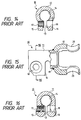
- a yoke as shown in Figures 13 - 14 or 15 - 16 of the accompanying drawings.
- Each of the yokes 10 described in the above-mentioned publication is constructed by fitting a coupling cylinder 11 and a coupling arm 12 to each other, and further welding them to each other.
- the coupling cylinder 11 is made into a tubular shape by press-shaping a metallic plate having sufficient rigidity such as a carbon steel plate, and has a split 13 formed in a circumferential portion thereof and a serration groove 14 formed in the inner peripheral surface thereof. Also, on one end portion (the left end portion as viewed in Figures 13 and 15) of the coupling cylinder 11, a pair of flange portions 15 and 16 are provided integrally with the coupling cylinder 11 with the split 13 interposed therebetween. These flange portions 15 and 16 are formed thickly by gathering portions of the metallic plate constituting the coupling cylinder 11 (the case of Figures 13 - 14) or by turning back a portion of the metallic plate by 180° (the case of Figures 15 - 16).
- flange portion 15 is formed with a threaded hole 17 and the other (the right as viewed in Figures 14 and 16) flange portion 16 is formed with a through-hole 18.
- the threaded hole 17 and the through-hole 18 are formed concentrically with each other, and the inner diameter of the through-hole 18 is made sufficiently larger than the inner diameter of the threaded hole 17, whereby the fore end portion of a bolt inserted in the through-hole 18 is threadably engageable with the threaded hole 17.
- the coupling arm 12 is made by press-shaping also a metallic plate having sufficient rigidity such as a carbon steel into a U-shape.
- the base portion of this coupling arm 12 is formed with a through-hole 19 and the opposite end portions of the coupling arm 12 are formed with concentric circular holes 20 and 20, respectively.
- the other end portion (the right end portion as viewed in Figures 13 and 15) of the coupling cylinder 11 is fitted in the through-hole 19 formed in the base portion of the coupling arm 12 and also, the outer peripheral surface of the other end portion of the coupling cylinder 11 and the marginal edge portion of the through-hole 19 in the base portion of the coupling arm 12 are welded to each other thereby providing a yoke 10 for the universal joint.
- one end portion of the bellows is coupled to the outer peripheral surface of the other end portion of the coupling cylinder 11 and the other end portion of the bellows is coupled to the base end portion of the coupling arm 12, both by welding.
- the bellows effect the transmission of a rotational force between the coupling cylinder 11 and the coupling arm 12 to thereby make steering possible.
- the bellows are crushed to thereby prevent any change in the inclination of the steering wheel or the pressure from below the steering wheel, thus alleviating the shock applied to the driver's body.
- the bellows are subjected to stress in the direction of rotation each time the steering wheel 1 is operated and therefore, when the diameter thereof is small, internal strain becomes great and sufficient durability cannot be secured.
- the thickness of the bellows is made great, it will be possible to secure durability, but it will become difficult for the bellows to be crushed on the occasion of a collision accident and shock energy absorbing capability will become insufficient. If the diameter of the bellows is made large without the thickness thereof being made great, durability and shock energy absorbing capability could be secured sufficiently.
- An aim of the invention is to mitigate or overcome at least some of the above-mentioned problems.
- the invention provides a yoke for a universal joint for a steering apparatus, the yoke comprising a first coupling portion and a second coupling portion each made by press-shaping a metallic plate, and a bellows-shaped member connecting said first coupling portion and said second coupling portion in series with each other;
- said bellows-shaped member is made by press-shaping an outer periphery of a thin-walled metal pipe into a waved shape.
- each of the flange portions of said first coupling portion is thickly formed by turning back a portion of a metallic plate by 180°.
- each of the flange portions of said first coupling portion is formed by gathering portions of a metallic plate.
- the invention also includes a steering apparatus having a universal joint incorporating the yoke.
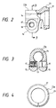
- a yoke 22 for a universal joint for a steering apparatus comprises a first coupling portion, or a coupling cylinder, 11a and a second coupling portion, or a coupling arm, 12a each made by press-shaping a metallic plate having sufficient rigidity such as a thick carbon steel plate and connected in series with each other by a metallic bellows-shaped member, or bellows, 21 interposed therebetween.
- the yoke 22 is incorporated into a universal joint with an other yoke and a cruciform shaft to thereby form a steering apparatus.
- the coupling cylinder 11a like the coupling cylinder 11 (see Figures 13 to 16) constituting the aforedescribed prior-art yoke 10, has an end portion formed into the shape of a substantially circular tube having an axially extending split 13 therein serrations 14 on an inner peripheral surface thereof, as shown in Figures 2 to 4.
- a pair of flange portions 15 and 16 are provided on an axially extending end portion (the left end portion as viewed in Figures 1 and 2) of the coupling cylinder lla with the split 13 interposed therebetween.
- flange portion 15 is formed with a threaded hole 17 and the other (the right as viewed in Figure 3) flange portion 16 is formed with a through-hole 18 concentric with the threaded hole 17.
- a bolt threadably engaged with the threaded hole 17 is inserted in the through-hole 18. Accordingly, the inner diameter of the through-hole 18 is larger than the inner diameter of the threaded hole 17 but smaller than the outer diameter of the head of the bolt.
- the other, opposite, end portion, or first coupling cylinder portion, 23 (the right end portion as viewed in Figures 1 and 2) of the coupling cylinder 11a is larger in diameter than the first mentioned end portion on which the serrations 14 are formed and permits one end portion (the left end portion as viewed in Figure 1) of the bellows 21 to be fitted to the outer peripheral surface thereof.
- the bellows 21 is made of a plastically deformable thin steel plate such as carbon steel or stainless steel, and has a waved portion 28 formed on the intermediate portion thereof and cylindrical portions 29 and 29 on the opposite end portions thereof.
- a thick metallic plate is first punched to thereby make a plate material blank, or plate, 24 as shown in Figures 5 and 6, and then this plate 24 is rounded into the shape of a circular tube, and a portion thereof is turned back to thereby make a blank 25 as shown in Figures 7 to 9.
- the first coupling cylinder portion 23 of a large diameter is formed on this blank 25.
- a pair of cut-aways 26 and 26 are formed in the intermediate portion of the plate 24 from the opposite end edges thereof and therefore, without the flange portions 15, 16 interfering with the first coupling cylinder portion 23, the work of forming these portions 15, 16 and 23 can be done.
- the first coupling cylinder portion 23 can be formed into an accurate cylindrical shape of a sufficiently large diameter and moreover, the pair of flange portions 15 and 16 can be made rightly parallel to each other.
- the threaded nole 17 and the through-hole 18 are then formed in the flange portions 15 and 16 of the blank 25 to thereby provide the coupling cylinder lla as shown in Figures 2 to 4.
- that portion of the outer peripheral surface of the first coupling cylinder portion 23 which is near the fore end thereof is cut as by lathing to thereby form a stepped portion 27 having a highly accurate cylindrical surface.
- the outer diameter of this stepped portion 27 is made substantially equal to the inner diameter of the cylindrical portion 29 of the bellows 21, and the level difference thereof from the remaining portion is preferably of a degree corresponding to the thickness of the bellows 21.
- the coupling arm 12a is made into a shape as shown in Figures 1 and 10 by press-shaping also a thick metallic plate into a U-shape.
- the mutually opposite free end portions of arms of this coupling arm 12a are formed with circular holes 20 and 20 concentric with each other and extending laterally of an axis of the yoke 22.
- a bearing cup (not shown) containing therein a needle bearing for supporting the cruciform shaft 9 ( Figure 12) is fitted into and fixed to the circular holes 20 and 20.
- a through-hole 19 extending in the direction of an axis of the yoke 22 is formed in a base end portion, or second coupling cylinder portion, 30 of the coupling arm 12a, and the base end portion 30 is substantially cylindrical.
- a stepped portion 31 having a highly accurate cylindrical surface is formed also on the outer peripheral surface of the second coupling cylinder portion 30 by cutting work such as lathing. The outer diameter of this stepped portion 31 is also made substantially equal to the inner diameter of the cylindrical portion 29 of the bellows 21.
- the cylindrical portion 29 on one end side of the bellows 21 is fitted onto the first coupling cylinder portion 23 and that portion of the outer peripheral surface of the first coupling cylinder portion 23 which is near the base end thereof and one end edge of the bellows 21 are welded together, as shown in Figure 1. Also, the cylindrical portion 29 on the other end side of the bellows 21 is fitted onto the second coupling cylinder portion 30 and that portion of the outer peripheral surface of the second coupling cylinder portion 30 which is near the base end thereof and the other end edge of the bellows 21 are welded together.
- the yoke 22 made in this manner is coupled to an other yoke through a cruciform shaft (not shown) like the aforedescribed prior-art yoke (see Figure 12), to thereby constitute a universal joint.
- This universal joint is incorporated into a steering apparatus as shown, for example, in Figure 11, and transmits the movement of a steering wheel 1 to a steering gear 4.
- the bellows 21 transmits rotational movement.
- an impact forced in a direction of compression over the axial direction (the left to right direction as viewed in Figure 1) is applied to the yoke 22, and the bellows 21 are crushed (the full length is shortened) by this impact force. Thereby, any change in the inclination of the steering wheel 1 or the pressure from below the steering wheel is prevented to alleviate the shock applied to a driver's body.
- the first coupling cylinder portion 23 formed on the coupling cylinder 11a can be made sufficiently large as compared with the outer diameter of the above-mentioned prior art coupling cylinder. Accordingly, the diameter of the bellows 21 provided between the coupling cylinder 11a and the coupling arm 12a can also be made sufficiently large. As a result, bellows of a small thickness and a large diameter are used as the bellows 21, whereby the durability of the bellows can be secured sufficiently and yet the absorbing performance for shock energy during collision can be secured.
- the pair of flange portions 15 and 16 are formed on the coupling cylinder 11a by turning back a metallic plate by 180°, but alternatively these flanges 15 and 16 may be formed by gathering portions of the metallic plate constituting the coupling cylinder 11a as in the prior-art structure shown in Figures 13 and 14. Also, the phase of the coupling cylinder 11a and the phase of the coupling arm 12a can be freely set to thereby improve the assembly property of the universal joint as in the case of the prior-art structure shown in Figures 13 to 16.
- the yoke 22 for a universal joint for a steering apparatus as described above with reference to Figures 1 to 10 can therefore obtain the following effects:
Landscapes
- Engineering & Computer Science (AREA)
- General Engineering & Computer Science (AREA)
- Mechanical Engineering (AREA)
- Chemical & Material Sciences (AREA)
- Combustion & Propulsion (AREA)
- Transportation (AREA)
- Physics & Mathematics (AREA)
- Acoustics & Sound (AREA)
- Aviation & Aerospace Engineering (AREA)
- Steering Controls (AREA)
- Diaphragms And Bellows (AREA)
Description
Claims (5)
- A yoke (22) for a universal joint for a steering apparatus, the yoke (22) comprising a first coupling portion (11a) and a second coupling portion (12a) each made by press-shaping a metallic plate, and a bellows-shaped member (21) connecting said first coupling portion (11a) and said second coupling portion (12a) in series with each other;said first coupling portion (11a) having an end portion formed into the shape of a substantially circular tube having an axially extending split (13) therein, serrations (14) on an inner peripheral surface thereof and a pair of flange portions (15, 16) provided integrally with the end portion with said split interposed therebetween, a threaded hole (17) being formed in one of said flange portions (15, 16) and a through-hole (18) which is concentric with said threaded hole (17) and into which a bolt threadably engageable with said threaded hole (17) is insertable being formed in the other flange portion (15, 16), said first coupling portion (lla) also having a substantially cylindrical opposite end portion (23), which has a larger outer diameter than said first mentioned end portion and to the outer peripheral surface of which one end portion of said bellows-shaped member (21) is fitted;said second coupling portion (12a) being made by press-shaping a metallic plate into a U-shape, having concentric substantially circular holes (20) in free end portions thereof, and having a substantially cylindrical base end portion (30) to which the other end portion of said bellows-shaped member (21) is fitted;said substantially cylindrical opposite end portion (23) of said first coupling portion (11a) and said first mentioned end portion of said bellows-shaped member (21) being welded to each other, and said substantially cylindrical base end portion (30) of said second coupling portion (12a) and said other end portion of said bellows-shaped member (21) being welded to each other.
- A yoke as claimed in claim 1, wherein said bellows-shaped member (21) is made by press-shaping an outer periphery of a thin-walled metal pipe into a waved shape.
- A yoke as claimed in claim 1 or 2, wherein each of the flange portions (15, 16) of said first coupling portion (lla) is thickly formed by turning back a portion of a metallic plate by 180°.
- A yoke as claimed in claim 1 or 2, wherein each of the flange portions (15, 16) of said first coupling portion (11a) is formed by gathering portions of a metallic plate.
- A steering apparatus having a universal joint incorporating a yoke (22) as claimed in any one of claims 1 to 4.
Applications Claiming Priority (2)
| Application Number | Priority Date | Filing Date | Title |
|---|---|---|---|
| JP215497/94 | 1994-09-09 | ||
| JP21549794A JP3186456B2 (en) | 1994-09-09 | 1994-09-09 | Yoke of universal joint for steering device |
Publications (2)
| Publication Number | Publication Date |
|---|---|
| EP0701070A1 EP0701070A1 (en) | 1996-03-13 |
| EP0701070B1 true EP0701070B1 (en) | 1998-07-29 |
Family
ID=16673376
Family Applications (1)
| Application Number | Title | Priority Date | Filing Date |
|---|---|---|---|
| EP95306267A Expired - Lifetime EP0701070B1 (en) | 1994-09-09 | 1995-09-07 | A universal joint yoke and a steering apparatus containing same |
Country Status (4)
| Country | Link |
|---|---|
| US (1) | US6022047A (en) |
| EP (1) | EP0701070B1 (en) |
| JP (1) | JP3186456B2 (en) |
| DE (1) | DE69503725T2 (en) |
Families Citing this family (18)
| Publication number | Priority date | Publication date | Assignee | Title |
|---|---|---|---|---|
| KR100369544B1 (en) * | 1996-10-29 | 2003-03-26 | 기아자동차주식회사 | Intermediate shaft for shock absorption of automotive steering gear |
| DE19812223A1 (en) * | 1998-03-19 | 1999-09-23 | Mayr Christian Gmbh & Co Kg | Corrugated tube transmits torque from one shaft to another |
| US6062982A (en) * | 1998-05-12 | 2000-05-16 | Trw Inc. | Force transmitting apparatus |
| JP3850209B2 (en) * | 2000-06-07 | 2006-11-29 | 株式会社日立製作所 | Power transmission shaft for vehicles |
| JP2002173040A (en) * | 2000-09-29 | 2002-06-18 | Honda Motor Co Ltd | Power steering device |
| US6949026B2 (en) | 2000-12-18 | 2005-09-27 | Timken Us Corporation | Axially compliant isolator |
| KR100418667B1 (en) * | 2001-04-18 | 2004-02-11 | 기아자동차주식회사 | Intermed shaft in steering arrangement for a motor vehicle |
| WO2003024204A2 (en) * | 2001-09-14 | 2003-03-27 | Crane Plastics Company Llc | Fence assembly with connectors |
| US6908109B2 (en) | 2002-03-14 | 2005-06-21 | Thyssenkrupp Presta Aktiengesellschaft | Steering gear shaft for a steering column of a motor vehicle |
| DE10211743A1 (en) | 2002-03-14 | 2003-11-06 | Thyssenkrupp Presta Ag Eschen | Steering spindle of a steering column for a motor vehicle |
| US6896290B2 (en) | 2002-03-14 | 2005-05-24 | Thyssenkrupp Presta Aktiengessellschaft | Steering gear shaft for a steering column of a motor vehicle |
| US7188866B2 (en) * | 2004-02-26 | 2007-03-13 | Delphi Technologies, Inc | Steering column assembly and method of fabricating the same |
| US20060035714A1 (en) * | 2004-08-13 | 2006-02-16 | Yi Qu | Collapsible vehicle driveshaft |
| JP2009006956A (en) * | 2007-06-29 | 2009-01-15 | Jtekt Corp | Shock absorbing vehicle steering system |
| JP5500378B2 (en) * | 2010-08-31 | 2014-05-21 | 株式会社ジェイテクト | Joint structure of shaft and universal joint yoke and vehicle steering system |
| JP5445660B2 (en) * | 2012-11-12 | 2014-03-19 | 日本精工株式会社 | Steering device |
| US9086097B2 (en) * | 2012-11-21 | 2015-07-21 | GM Global Technology Operations LLC | Universal joint |
| CN105235736A (en) * | 2015-11-03 | 2016-01-13 | 北汽银翔汽车有限公司 | Novel steering transmission shaft energy absorption and vibration reduction structure |
Family Cites Families (26)
| Publication number | Priority date | Publication date | Assignee | Title |
|---|---|---|---|---|
| US2114663A (en) * | 1937-01-23 | 1938-04-19 | James B Bradshaw | Safety steering post for automobiles |
| GB522590A (en) * | 1938-12-10 | 1940-06-21 | George Cheswick | Improvements in exhaust gas systems of internal-combustion engines |
| US3232076A (en) * | 1962-12-31 | 1966-02-01 | Edward V Sundt | Flexible coupling for rotating shafts |
| US3401576A (en) * | 1966-05-23 | 1968-09-17 | Robert E. Eckels | Collapsible steering column |
| US3482466A (en) * | 1967-01-24 | 1969-12-09 | Helmut Orlich | Torsion device for steering columns |
| US3434367A (en) * | 1967-09-01 | 1969-03-25 | Chrysler Corp | Steering column |
| FR2133343A5 (en) * | 1971-04-16 | 1972-11-24 | Glaenzer Spicer Sa | |
| DE2212713C3 (en) * | 1972-03-16 | 1985-08-29 | Adam Opel AG, 6090 Rüsselsheim | Safety steering column for vehicles, in particular motor vehicles |
| US4009622A (en) * | 1975-10-28 | 1977-03-01 | Hinderks M V | Collapsible member |
| JPS5383231A (en) * | 1976-12-29 | 1978-07-22 | Toray Ind Inc | Automotive drive propelling shaft |
| DE2738179A1 (en) * | 1977-08-24 | 1979-03-01 | Klein Kg Eugen | Safety steering column for vehicle - has shaft with collapsible sleeve manufactured by pressing or extrusion and welding seams |
| SE406303B (en) * | 1977-12-12 | 1979-02-05 | Saab Scania Ab | ARRANGEMENTS AT STEERING INSTALLATIONS IN MOTOR VEHICLES |
| DE3446749A1 (en) * | 1984-12-21 | 1986-07-03 | Messerschmitt-Bölkow-Blohm GmbH, 8012 Ottobrunn | Safety steering column for motor vehicles |
| JPS6313634A (en) * | 1986-07-07 | 1988-01-20 | Toyota Motor Corp | Manufacture of energy absorbing member for steering shaft |
| JPS6313863A (en) * | 1986-07-07 | 1988-01-21 | Toyota Motor Corp | Primary collision prevention steering shaft |
| DE3711917A1 (en) * | 1987-04-09 | 1988-08-18 | Daimler Benz Ag | Steering system for motor vehicles |
| DE3828665A1 (en) * | 1988-08-24 | 1990-03-15 | Kurt Ehrenberg | Joint fork formed from a sheet-metal blank |
| US5259818A (en) * | 1989-04-14 | 1993-11-09 | Fuji Kiko Company, Limited | Stroke absorbing type intermediate shaft for vehicular steering column and method for assembling the same |
| US5222913A (en) * | 1989-05-30 | 1993-06-29 | Nippon Seiko Kabushiki Kaisha | Resilient connector for steering shaft |
| JP2534772B2 (en) * | 1989-07-07 | 1996-09-18 | 日本精工株式会社 | Universal joint yoke manufacturing method |
| FR2655110B1 (en) * | 1989-11-30 | 1992-03-27 | Ecia Equip Composants Ind Auto | DEVICE FOR FILTERING VIBRATIONS BETWEEN TWO SHAFTS, PARTICULARLY BETWEEN TWO PARTS OF A STEERING COLUMN. |
| IT1240950B (en) * | 1990-06-12 | 1993-12-27 | Fiat Auto Spa | STEERING COLUMN WITH ENERGY ABSORPTION COLLASSING SYSTEM |
| JPH05155342A (en) * | 1991-12-04 | 1993-06-22 | Toyota Motor Corp | Shock absorbing steering column |
| US5293973A (en) * | 1991-12-16 | 1994-03-15 | Volkswagen Ag | Deformation member having an eversion portion |
| JP3094053B2 (en) * | 1994-02-25 | 2000-10-03 | 富士機工株式会社 | Vehicle steering system |
| US5740699A (en) * | 1995-04-06 | 1998-04-21 | Spar Aerospace Limited | Wrist joint which is longitudinally extendible |
-
1994
- 1994-09-09 JP JP21549794A patent/JP3186456B2/en not_active Expired - Fee Related
-
1995
- 1995-08-25 US US08/519,614 patent/US6022047A/en not_active Expired - Lifetime
- 1995-09-07 DE DE69503725T patent/DE69503725T2/en not_active Expired - Lifetime
- 1995-09-07 EP EP95306267A patent/EP0701070B1/en not_active Expired - Lifetime
Also Published As
| Publication number | Publication date |
|---|---|
| JPH0872730A (en) | 1996-03-19 |
| EP0701070A1 (en) | 1996-03-13 |
| JP3186456B2 (en) | 2001-07-11 |
| US6022047A (en) | 2000-02-08 |
| DE69503725T2 (en) | 1999-02-25 |
| DE69503725D1 (en) | 1998-09-03 |
Similar Documents
| Publication | Publication Date | Title |
|---|---|---|
| EP0701070B1 (en) | A universal joint yoke and a steering apparatus containing same | |
| US4269043A (en) | Coupling for resiliently connecting two shafts for transmission of torque | |
| JP2534772B2 (en) | Universal joint yoke manufacturing method | |
| EP1772346B1 (en) | Slip joint for use in steering system | |
| US5188474A (en) | Yoke for universal joint | |
| JP3646556B2 (en) | Elastic shaft coupling | |
| KR0161568B1 (en) | Elastic universal joint | |
| JP3186424B2 (en) | Energy absorbing intermediate shaft | |
| JP2532378Y2 (en) | Elastic universal joint | |
| JP2017136889A (en) | Steering device | |
| US6190259B1 (en) | Steering joint device for a car | |
| EP0957276A2 (en) | Force transmitting apparatus | |
| WO2020153408A1 (en) | Torque transmission shaft | |
| JP7671053B2 (en) | Intermediate Shaft | |
| JPH0422111Y2 (en) | ||
| US6623363B2 (en) | Universal joint yoke and method of making same | |
| JP2001012490A (en) | Yoke for universal joint | |
| CN100451370C (en) | Vehicle steering device | |
| JP3389721B2 (en) | Elastic universal joint | |
| EP1632419B1 (en) | Joint section between shaft and universal joint yoke | |
| JP4070567B2 (en) | Elastic universal joint | |
| US7393282B2 (en) | Coupling structure of steering torque transmitting member for steering shaft | |
| JP2572521Y2 (en) | Yoke for universal joint | |
| JP3769846B2 (en) | Elastic universal joint | |
| JPH09324823A (en) | Double Cardan constant velocity joint |
Legal Events
| Date | Code | Title | Description |
|---|---|---|---|
| PUAI | Public reference made under article 153(3) epc to a published international application that has entered the european phase |
Free format text: ORIGINAL CODE: 0009012 |
|
| AK | Designated contracting states |
Kind code of ref document: A1 Designated state(s): DE FR GB |
|
| 17P | Request for examination filed |
Effective date: 19960531 |
|
| 17Q | First examination report despatched |
Effective date: 19961113 |
|
| GRAG | Despatch of communication of intention to grant |
Free format text: ORIGINAL CODE: EPIDOS AGRA |
|
| GRAG | Despatch of communication of intention to grant |
Free format text: ORIGINAL CODE: EPIDOS AGRA |
|
| GRAH | Despatch of communication of intention to grant a patent |
Free format text: ORIGINAL CODE: EPIDOS IGRA |
|
| GRAH | Despatch of communication of intention to grant a patent |
Free format text: ORIGINAL CODE: EPIDOS IGRA |
|
| GRAA | (expected) grant |
Free format text: ORIGINAL CODE: 0009210 |
|
| AK | Designated contracting states |
Kind code of ref document: B1 Designated state(s): DE FR GB |
|
| PG25 | Lapsed in a contracting state [announced via postgrant information from national office to epo] |
Ref country code: FR Free format text: LAPSE BECAUSE OF FAILURE TO SUBMIT A TRANSLATION OF THE DESCRIPTION OR TO PAY THE FEE WITHIN THE PRESCRIBED TIME-LIMIT Effective date: 19980729 |
|
| REF | Corresponds to: |
Ref document number: 69503725 Country of ref document: DE Date of ref document: 19980903 |
|
| EN | Fr: translation not filed | ||
| PLBE | No opposition filed within time limit |
Free format text: ORIGINAL CODE: 0009261 |
|
| STAA | Information on the status of an ep patent application or granted ep patent |
Free format text: STATUS: NO OPPOSITION FILED WITHIN TIME LIMIT |
|
| 26N | No opposition filed | ||
| REG | Reference to a national code |
Ref country code: GB Ref legal event code: IF02 |
|
| REG | Reference to a national code |
Ref country code: GB Ref legal event code: 746 Effective date: 20030915 |
|
| PGFP | Annual fee paid to national office [announced via postgrant information from national office to epo] |
Ref country code: GB Payment date: 20080910 Year of fee payment: 14 |
|
| GBPC | Gb: european patent ceased through non-payment of renewal fee |
Effective date: 20090907 |
|
| PG25 | Lapsed in a contracting state [announced via postgrant information from national office to epo] |
Ref country code: GB Free format text: LAPSE BECAUSE OF NON-PAYMENT OF DUE FEES Effective date: 20090907 |
|
| PGFP | Annual fee paid to national office [announced via postgrant information from national office to epo] |
Ref country code: DE Payment date: 20140903 Year of fee payment: 20 |
|
| REG | Reference to a national code |
Ref country code: DE Ref legal event code: R071 Ref document number: 69503725 Country of ref document: DE |