EP0701036A1 - Elektronisches schloss "chiplock" - Google Patents
Elektronisches schloss "chiplock" Download PDFInfo
- Publication number
- EP0701036A1 EP0701036A1 EP94930840A EP94930840A EP0701036A1 EP 0701036 A1 EP0701036 A1 EP 0701036A1 EP 94930840 A EP94930840 A EP 94930840A EP 94930840 A EP94930840 A EP 94930840A EP 0701036 A1 EP0701036 A1 EP 0701036A1
- Authority
- EP
- European Patent Office
- Prior art keywords
- bar
- electronic lock
- blocking
- lock
- limiter
- Prior art date
- Legal status (The legal status is an assumption and is not a legal conclusion. Google has not performed a legal analysis and makes no representation as to the accuracy of the status listed.)
- Granted
Links
Images

Classifications
-
- E—FIXED CONSTRUCTIONS
- E05—LOCKS; KEYS; WINDOW OR DOOR FITTINGS; SAFES
- E05B—LOCKS; ACCESSORIES THEREFOR; HANDCUFFS
- E05B47/00—Operating or controlling locks or other fastening devices by electric or magnetic means
- E05B47/06—Controlling mechanically-operated bolts by electro-magnetically-operated detents
- E05B47/0603—Controlling mechanically-operated bolts by electro-magnetically-operated detents the detent moving rectilinearly
Definitions
- the invention relates to an automatic that uses fixing mechanisms and locking devices, and particularly to electronic locks for doors, safes, vehicles etc.
- a disadvantage of locks of this type is in a power coupling between the bar and the control element, which coupling is performed via a sufficiently powerful electromagnet. Because of a high power consumption of such a lock it may operate only from external mains, or energy-intensive battery.
- This invention provides a reduction of a power consumed by the electronic lock.
- an electronic lock comprising a bar, a bar shift mechanism, and a blocking device;
- said blocking device is made in the form of an electromechanical catch including interactive elements mounted with the possibility of their mutual shifting and of their electroadhesive fixing and said blocking device is coupled to a limiter blocking the shift of said bar.
- the Applicant does not know locking devices and more particularly electronic locks having the same set of essential features. This permits to consider the present invention being met the PCT criterion of novelty (N).
- the Applicant knows systems in which the electroadhesive effect is employed for fixing processed details on a working plate (USSR Author's Certificates N o 1291395, Int. Cl. B 25 J 15/06, published 1987; N o 1320057, Int. Cl. B 25 J 15/06, published 1987; N o 1451000, Int. Cl. B 25 J 15/06, published 1989).
- USSR Author's Certificates N o 1291395, Int. Cl. B 25 J 15/06, published 1987; N o 1320057, Int. Cl. B 25 J 15/06, published 1987; N o 1451000, Int. Cl. B 25 J 15/06, published 1989.
- the employing of the electro-adhesive effect to blocking elements mutually moved in mechanical devices and more particularly in door locks isn't known from the Applicant. This permits to consider the present invention being met the PCT criterion of inventive step (IS).
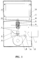
- Fig. 1 to 3 shows, in a schematical view, locations of main units of the electronic lock in different phases of its operating.
- An electronic lock includes a bar 1, a bar shift mechanism consisting of a riegel 2 (bolt) and a control lever 3 having a peg 4.
- a vertical hole (marked on the local cross-section) is made in a body of the riegel (bolt) 2, in which hole a cylindric pin 7 is inserted having a transversal tip 5 going out of a slot in the lower plane part of the riegel 2 (bolt).
- the pin 7 is under an effect of a returning spring 6 by means of the transversal tip 5.
- a bar shifting blocking device has a limiter 8 moved by the pin 7 and a spring 10 in a fixed bush 9 and coupled to a moving plate 11 of the electromechanical catch by a chain 13, a second plate 12 of the catch is fixed in a lock body 14.
- the catch plates 11, 12 are divided by a thin dielectric clearance, and in the simplest case the surfaces of that both plates 11, 12, turned one to the other, are produced with a high polishing degree and have a conductivity. From the electrical point of view the catch is equivalent to a capacitor: once a voltage is applied on its plates they are charging by opposite polar charges. As known from the background art and particularly from the above mentioned references, the electrostatic attraction arises between the charged plates 11, 12 leading, under some condition, to a considerable mutual adhesion of these plates 11, 12, that is so called electroadhesive interaction . In a shown schematic structure these catch plates 11, 12 are able to move mutually and their mutual location may be fixed at an arbitrary moment due to the electroadhesion, by applying an electrical charge to these plates 11, 12.
- Fig. 1 shows a starting state of the electronic lock mechanism.
- the bar 1 is slid out of the body 14 (the state of "lock is closed"), the limiter 8 of the blocking device is lowered into the vertical hole of the riegel 2 (bolt) by the spring 10 thus blocking a shift of the bar 1.
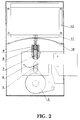
- Fig.2 illustrates "cocking" of the blocking device.
- the control lever 3 When the control lever 3 is turned clockwise, its left cam forces the tip 5 and raises the pin 7 which in its turn raises the limiter 8. In the final position shown in the Fig.2 the pin 7 comes into the fixed bush 9 thus operating as a limiter.
- the moving plate 11 of the electromechanical catch shifts away from its starting position with regard to the fixed plate 12.
- control lever 3 After the control lever 3 is turned counter-clockwise to its starting position there are two possible versions of the whole mechanism to operate.
- the first version "idling" takes place when the catch plates 11, 12 are not supplied by the voltage. In this case an interaction between these plates is absent, and they are free in their mutual movement.
- the spring 10 lowers the limiter 8 after the pin 7 is lowered to its starting position (Fig. 1).
- the second version "deblocking the lock" takes place when the catch plates 11, 12 are supplied by the voltage big enough for such an electroadhesive coupling of plates 11, 12 that counteracts a force of the tensed spring 10 and thus keeps the limiter 8 in a "cocked” state.
- the pin 7 is being hid by its returning spring 6 into the vertical hole of the riegel 2 (bolt) enabling it to shift longitudinally.
- Fig.3 shows the final state of the lock mechanism.
- the bar 1 is drew into the lock body 14 (the state of "lock is open”).
- the longitudinal shift of the bar riegel 2 (bolt) is performed by the peg 4 of the control lever 3 acting onto the vertical slot of the riegel 2 (bolt).
- this invention may be used as the electromechanical blocking mechanism in automatic systems and particularly for its proper purpose, i.e. as an electronic lock for doors of premises, safes, vehicles, etc.
- a simple design of the discussed electronic lock allows to produce it in a large-scale production.
- a use of the electroadhesive effect based on electrostatic interaction of mechanism elements for blocking the mechanisms requires much smaller power consumption unlike of the use of the electrodynamic interaction in known blocking mechanisms having electromagnetic coils.
- this invention allows to use the piezoelectricity (and the triboelectricity, or other types and methods of a quasistatic charge accumulation) to supply electronic locks having electroadhesive blocking devices.
- the described lock elements the bar, the bar shifting mechanism, methods for mechanical blocking of the bar shifting mechanism by means of the limiter, the form and the constructions of electroadhesive catch elements etc., may differ.
Landscapes
- Lock And Its Accessories (AREA)
- Oscillators With Electromechanical Resonators (AREA)
- Nitrogen And Oxygen Or Sulfur-Condensed Heterocyclic Ring Systems (AREA)
- Mounting Of Printed Circuit Boards And The Like (AREA)
- Control Of Fluid Gearings (AREA)
- Electrophonic Musical Instruments (AREA)
- Fixed Capacitors And Capacitor Manufacturing Machines (AREA)
Applications Claiming Priority (3)
| Application Number | Priority Date | Filing Date | Title |
|---|---|---|---|
| RU93027411/12A RU2042028C1 (ru) | 1993-05-12 | 1993-05-12 | Электронный замок |
| RU93027411 | 1993-05-12 | ||
| PCT/RU1994/000117 WO1994027012A1 (fr) | 1993-05-12 | 1994-05-11 | Serrure electronique 'chiplock' |
Publications (3)
| Publication Number | Publication Date |
|---|---|
| EP0701036A1 true EP0701036A1 (de) | 1996-03-13 |
| EP0701036A4 EP0701036A4 (de) | 1996-08-28 |
| EP0701036B1 EP0701036B1 (de) | 1999-09-15 |
Family
ID=20141882
Family Applications (1)
| Application Number | Title | Priority Date | Filing Date |
|---|---|---|---|
| EP94930840A Expired - Lifetime EP0701036B1 (de) | 1993-05-12 | 1994-05-11 | Elektronisches schloss "chiplock" |
Country Status (9)
| Country | Link |
|---|---|
| EP (1) | EP0701036B1 (de) |
| AT (1) | ATE184672T1 (de) |
| AU (1) | AU6939094A (de) |
| CA (1) | CA2162863C (de) |
| DE (1) | DE69420722T2 (de) |
| ES (1) | ES2140564T3 (de) |
| FI (1) | FI111748B (de) |
| RU (1) | RU2042028C1 (de) |
| WO (1) | WO1994027012A1 (de) |
Cited By (2)
| Publication number | Priority date | Publication date | Assignee | Title |
|---|---|---|---|---|
| US7334443B2 (en) | 2002-02-22 | 2008-02-26 | Master Lock Company Llc | Radio frequency electronic lock |
| EP1178597A4 (de) * | 1999-04-14 | 2010-08-04 | Martyn Sergeevich Nunuparov | Elektrostatische Vorrichtung zum mechanischen Festklemmen |
Families Citing this family (1)
| Publication number | Priority date | Publication date | Assignee | Title |
|---|---|---|---|---|
| RU2580094C1 (ru) * | 2015-01-12 | 2016-04-10 | Дмитрий Юрьевич Яковлев | Электронный навесной замок |
Family Cites Families (7)
| Publication number | Priority date | Publication date | Assignee | Title |
|---|---|---|---|---|
| US4053939A (en) * | 1974-11-25 | 1977-10-11 | Kokusai Gijutsu Kaihatsu Kabushiki Kaisha | Electric lock system |
| DE2833453A1 (de) * | 1978-07-29 | 1980-02-07 | Ymos Metallwerke Wolf & Becker | Magnetschloss |
| GB2069590B (en) * | 1981-02-13 | 1984-01-11 | Malkmus Doernemann Carola | Lock bolt arrangement |
| HU187947B (en) * | 1983-07-06 | 1986-03-28 | Elzett Muevek,Hu | Magnetic lock insert |
| EP0299642B1 (de) * | 1987-07-16 | 1992-03-25 | John Chu | Elektrostatisch aktivierte Schaltvorrichtung |
| GB8908386D0 (en) * | 1989-04-13 | 1989-06-01 | Chubb Lips Nederland Bv | Locks |
| SU1694066A3 (ru) * | 1990-06-29 | 1991-11-23 | В.Н. Фаерман | Электромагнитный замок |
-
1993
- 1993-05-12 RU RU93027411/12A patent/RU2042028C1/ru not_active IP Right Cessation
-
1994
- 1994-05-11 AT AT94930840T patent/ATE184672T1/de active
- 1994-05-11 AU AU69390/94A patent/AU6939094A/en not_active Abandoned
- 1994-05-11 EP EP94930840A patent/EP0701036B1/de not_active Expired - Lifetime
- 1994-05-11 ES ES94930840T patent/ES2140564T3/es not_active Expired - Lifetime
- 1994-05-11 WO PCT/RU1994/000117 patent/WO1994027012A1/ru not_active Ceased
- 1994-05-11 DE DE69420722T patent/DE69420722T2/de not_active Expired - Fee Related
- 1994-05-11 CA CA002162863A patent/CA2162863C/en not_active Expired - Fee Related
-
1995
- 1995-11-10 FI FI955423A patent/FI111748B/fi not_active IP Right Cessation
Cited By (2)
| Publication number | Priority date | Publication date | Assignee | Title |
|---|---|---|---|---|
| EP1178597A4 (de) * | 1999-04-14 | 2010-08-04 | Martyn Sergeevich Nunuparov | Elektrostatische Vorrichtung zum mechanischen Festklemmen |
| US7334443B2 (en) | 2002-02-22 | 2008-02-26 | Master Lock Company Llc | Radio frequency electronic lock |
Also Published As
| Publication number | Publication date |
|---|---|
| ATE184672T1 (de) | 1999-10-15 |
| CA2162863C (en) | 1999-11-16 |
| DE69420722T2 (de) | 2000-04-27 |
| FI955423A0 (fi) | 1995-11-10 |
| WO1994027012A1 (fr) | 1994-11-24 |
| CA2162863A1 (en) | 1994-11-24 |
| DE69420722D1 (de) | 1999-10-21 |
| EP0701036A4 (de) | 1996-08-28 |
| RU2042028C1 (ru) | 1995-08-20 |
| AU6939094A (en) | 1994-12-12 |
| FI111748B (fi) | 2003-09-15 |
| ES2140564T3 (es) | 2000-03-01 |
| FI955423L (fi) | 1995-11-10 |
| EP0701036B1 (de) | 1999-09-15 |
Similar Documents
| Publication | Publication Date | Title |
|---|---|---|
| US5839306A (en) | Electronic lock "chiplock" | |
| US5000018A (en) | Hardware, in particular for doors or the like | |
| CN1200427A (zh) | 用于电子锁的由螺线管操纵的锁簧控制 | |
| EP0877134A2 (de) | Solenoidsteuerung mit elektronischer Rücksetzschaltung für ein elektronisches Schloss | |
| KR101067945B1 (ko) | 전자 잠금기구 및 이를 포함한 자물쇠 | |
| AU2007257628A1 (en) | Locking device | |
| US8047031B2 (en) | Lock portion with piezo-electric actuator and anti-tamper circuit | |
| WO2000031757A1 (en) | Autosecuring solenoid | |
| WO2006109299A2 (en) | Inertial blocking mechanism | |
| EP0701036A1 (de) | Elektronisches schloss "chiplock" | |
| KR20200133342A (ko) | 해제 기구, 에너지 하베스팅 장치 및 전자식 잠금 시스템 | |
| RU2441968C2 (ru) | Электронный замок с пассивным средством блокировки | |
| EP0299642B1 (de) | Elektrostatisch aktivierte Schaltvorrichtung | |
| EP0886285A3 (de) | Bistabile selbstnachstellende Betätigungseinrichtung | |
| RU2666310C1 (ru) | Электромеханический замок | |
| GB2123078A (en) | Electrically lockable fastening | |
| RU2174581C1 (ru) | Электромеханический замок | |
| RU2615713C1 (ru) | Электромагнитный замок | |
| EP2017410B1 (de) | Elektronischer Sperrmechanismus | |
| RU2266383C1 (ru) | Запирающее устройство | |
| CN209723904U (zh) | 一种自助机开门用的新型电子锁 | |
| CN209687047U (zh) | 一种防技术开启的电磁离合器 | |
| CN109610943A (zh) | 一种自助机开门用的新型电子锁 | |
| RU2283411C1 (ru) | Электромагнитный замок | |
| CN214273256U (zh) | 一种锁控装置以及设备 |
Legal Events
| Date | Code | Title | Description |
|---|---|---|---|
| PUAI | Public reference made under article 153(3) epc to a published international application that has entered the european phase |
Free format text: ORIGINAL CODE: 0009012 |
|
| 17P | Request for examination filed |
Effective date: 19951211 |
|
| AK | Designated contracting states |
Kind code of ref document: A1 Designated state(s): AT BE CH DE DK ES FR GB GR IE IT LI LU MC NL PT SE |
|
| A4 | Supplementary search report drawn up and despatched | ||
| AK | Designated contracting states |
Kind code of ref document: A4 Designated state(s): AT BE CH DE DK ES FR GB GR IE IT LI LU MC NL PT SE |
|
| 17Q | First examination report despatched |
Effective date: 19980421 |
|
| GRAG | Despatch of communication of intention to grant |
Free format text: ORIGINAL CODE: EPIDOS AGRA |
|
| GRAG | Despatch of communication of intention to grant |
Free format text: ORIGINAL CODE: EPIDOS AGRA |
|
| GRAG | Despatch of communication of intention to grant |
Free format text: ORIGINAL CODE: EPIDOS AGRA |
|
| GRAH | Despatch of communication of intention to grant a patent |
Free format text: ORIGINAL CODE: EPIDOS IGRA |
|
| GRAH | Despatch of communication of intention to grant a patent |
Free format text: ORIGINAL CODE: EPIDOS IGRA |
|
| GRAA | (expected) grant |
Free format text: ORIGINAL CODE: 0009210 |
|
| AK | Designated contracting states |
Kind code of ref document: B1 Designated state(s): AT BE CH DE DK ES FR GB GR IE IT LI LU MC NL PT SE |
|
| PG25 | Lapsed in a contracting state [announced via postgrant information from national office to epo] |
Ref country code: SE Free format text: THE PATENT HAS BEEN ANNULLED BY A DECISION OF A NATIONAL AUTHORITY Effective date: 19990915 Ref country code: LI Free format text: LAPSE BECAUSE OF FAILURE TO SUBMIT A TRANSLATION OF THE DESCRIPTION OR TO PAY THE FEE WITHIN THE PRESCRIBED TIME-LIMIT Effective date: 19990915 Ref country code: GR Free format text: LAPSE BECAUSE OF NON-PAYMENT OF DUE FEES Effective date: 19990915 Ref country code: CH Free format text: LAPSE BECAUSE OF FAILURE TO SUBMIT A TRANSLATION OF THE DESCRIPTION OR TO PAY THE FEE WITHIN THE PRESCRIBED TIME-LIMIT Effective date: 19990915 Ref country code: BE Free format text: LAPSE BECAUSE OF FAILURE TO SUBMIT A TRANSLATION OF THE DESCRIPTION OR TO PAY THE FEE WITHIN THE PRESCRIBED TIME-LIMIT Effective date: 19990915 Ref country code: AT Free format text: LAPSE BECAUSE OF FAILURE TO SUBMIT A TRANSLATION OF THE DESCRIPTION OR TO PAY THE FEE WITHIN THE PRESCRIBED TIME-LIMIT Effective date: 19990915 |
|
| REF | Corresponds to: |
Ref document number: 184672 Country of ref document: AT Date of ref document: 19991015 Kind code of ref document: T |
|
| REG | Reference to a national code |
Ref country code: CH Ref legal event code: EP |
|
| REF | Corresponds to: |
Ref document number: 69420722 Country of ref document: DE Date of ref document: 19991021 |
|
| REG | Reference to a national code |
Ref country code: IE Ref legal event code: FG4D |
|
| ITF | It: translation for a ep patent filed | ||
| PG25 | Lapsed in a contracting state [announced via postgrant information from national office to epo] |
Ref country code: PT Free format text: LAPSE BECAUSE OF FAILURE TO SUBMIT A TRANSLATION OF THE DESCRIPTION OR TO PAY THE FEE WITHIN THE PRESCRIBED TIME-LIMIT Effective date: 19991215 Ref country code: DK Free format text: LAPSE BECAUSE OF FAILURE TO SUBMIT A TRANSLATION OF THE DESCRIPTION OR TO PAY THE FEE WITHIN THE PRESCRIBED TIME-LIMIT Effective date: 19991215 |
|
| ET | Fr: translation filed | ||
| REG | Reference to a national code |
Ref country code: ES Ref legal event code: FG2A Ref document number: 2140564 Country of ref document: ES Kind code of ref document: T3 |
|
| REG | Reference to a national code |
Ref country code: CH Ref legal event code: PL |
|
| PG25 | Lapsed in a contracting state [announced via postgrant information from national office to epo] |
Ref country code: LU Free format text: LAPSE BECAUSE OF NON-PAYMENT OF DUE FEES Effective date: 20000511 Ref country code: IE Free format text: LAPSE BECAUSE OF NON-PAYMENT OF DUE FEES Effective date: 20000511 |
|
| PLBE | No opposition filed within time limit |
Free format text: ORIGINAL CODE: 0009261 |
|
| STAA | Information on the status of an ep patent application or granted ep patent |
Free format text: STATUS: NO OPPOSITION FILED WITHIN TIME LIMIT |
|
| 26N | No opposition filed | ||
| PG25 | Lapsed in a contracting state [announced via postgrant information from national office to epo] |
Ref country code: MC Free format text: LAPSE BECAUSE OF NON-PAYMENT OF DUE FEES Effective date: 20001130 |
|
| REG | Reference to a national code |
Ref country code: IE Ref legal event code: MM4A |
|
| REG | Reference to a national code |
Ref country code: GB Ref legal event code: IF02 |
|
| PGFP | Annual fee paid to national office [announced via postgrant information from national office to epo] |
Ref country code: NL Payment date: 20060515 Year of fee payment: 13 |
|
| PGFP | Annual fee paid to national office [announced via postgrant information from national office to epo] |
Ref country code: ES Payment date: 20060530 Year of fee payment: 13 |
|
| PGFP | Annual fee paid to national office [announced via postgrant information from national office to epo] |
Ref country code: IT Payment date: 20060531 Year of fee payment: 13 |
|
| PGFP | Annual fee paid to national office [announced via postgrant information from national office to epo] |
Ref country code: DE Payment date: 20070522 Year of fee payment: 14 |
|
| PGFP | Annual fee paid to national office [announced via postgrant information from national office to epo] |
Ref country code: GB Payment date: 20070522 Year of fee payment: 14 |
|
| PG25 | Lapsed in a contracting state [announced via postgrant information from national office to epo] |
Ref country code: NL Free format text: LAPSE BECAUSE OF NON-PAYMENT OF DUE FEES Effective date: 20071201 |
|
| NLV4 | Nl: lapsed or anulled due to non-payment of the annual fee |
Effective date: 20071201 |
|
| PGFP | Annual fee paid to national office [announced via postgrant information from national office to epo] |
Ref country code: FR Payment date: 20070516 Year of fee payment: 14 |
|
| REG | Reference to a national code |
Ref country code: ES Ref legal event code: FD2A Effective date: 20070512 |
|
| PG25 | Lapsed in a contracting state [announced via postgrant information from national office to epo] |
Ref country code: ES Free format text: LAPSE BECAUSE OF NON-PAYMENT OF DUE FEES Effective date: 20070512 |
|
| GBPC | Gb: european patent ceased through non-payment of renewal fee |
Effective date: 20080511 |
|
| REG | Reference to a national code |
Ref country code: FR Ref legal event code: ST Effective date: 20090119 |
|
| PG25 | Lapsed in a contracting state [announced via postgrant information from national office to epo] |
Ref country code: FR Free format text: LAPSE BECAUSE OF NON-PAYMENT OF DUE FEES Effective date: 20080602 Ref country code: DE Free format text: LAPSE BECAUSE OF NON-PAYMENT OF DUE FEES Effective date: 20081202 |
|
| PG25 | Lapsed in a contracting state [announced via postgrant information from national office to epo] |
Ref country code: GB Free format text: LAPSE BECAUSE OF NON-PAYMENT OF DUE FEES Effective date: 20080511 |
|
| PG25 | Lapsed in a contracting state [announced via postgrant information from national office to epo] |
Ref country code: IT Free format text: LAPSE BECAUSE OF NON-PAYMENT OF DUE FEES Effective date: 20070511 |