EP0701017A1 - Method and device for treating stitches of textile products - Google Patents
Method and device for treating stitches of textile products Download PDFInfo
- Publication number
- EP0701017A1 EP0701017A1 EP95830327A EP95830327A EP0701017A1 EP 0701017 A1 EP0701017 A1 EP 0701017A1 EP 95830327 A EP95830327 A EP 95830327A EP 95830327 A EP95830327 A EP 95830327A EP 0701017 A1 EP0701017 A1 EP 0701017A1
- Authority
- EP
- European Patent Office
- Prior art keywords
- needle
- mesh
- punch
- stitch
- punches
- Prior art date
- Legal status (The legal status is an assumption and is not a legal conclusion. Google has not performed a legal analysis and makes no representation as to the accuracy of the status listed.)
- Granted
Links
- 239000004753 textile Substances 0.000 title claims description 28
- 238000000034 method Methods 0.000 title claims description 16
- 238000012546 transfer Methods 0.000 claims abstract description 25
- 238000009940 knitting Methods 0.000 claims abstract description 17
- 210000000056 organ Anatomy 0.000 claims description 13
- 238000004519 manufacturing process Methods 0.000 claims description 8
- 238000013459 approach Methods 0.000 claims description 4
- 230000002269 spontaneous effect Effects 0.000 claims description 4
- 230000002457 bidirectional effect Effects 0.000 claims description 3
- 230000000694 effects Effects 0.000 claims description 3
- 238000006243 chemical reaction Methods 0.000 claims description 2
- 230000008021 deposition Effects 0.000 claims 1
- 238000005070 sampling Methods 0.000 description 7
- 238000009941 weaving Methods 0.000 description 5
- 238000006073 displacement reaction Methods 0.000 description 3
- 210000001520 comb Anatomy 0.000 description 2
- 230000008878 coupling Effects 0.000 description 2
- 238000010168 coupling process Methods 0.000 description 2
- 238000005859 coupling reaction Methods 0.000 description 2
- 238000000151 deposition Methods 0.000 description 2
- 229940082150 encore Drugs 0.000 description 2
- 230000000717 retained effect Effects 0.000 description 2
- 238000007493 shaping process Methods 0.000 description 2
- 238000011282 treatment Methods 0.000 description 2
- 229920000742 Cotton Polymers 0.000 description 1
- 210000003323 beak Anatomy 0.000 description 1
- 230000015572 biosynthetic process Effects 0.000 description 1
- 238000011161 development Methods 0.000 description 1
- 239000004744 fabric Substances 0.000 description 1
- 238000003754 machining Methods 0.000 description 1
- 230000014759 maintenance of location Effects 0.000 description 1
- 238000012545 processing Methods 0.000 description 1
- 238000003307 slaughter Methods 0.000 description 1
- 238000012549 training Methods 0.000 description 1
- 238000013519 translation Methods 0.000 description 1
Images


Classifications
-
- D—TEXTILES; PAPER
- D04—BRAIDING; LACE-MAKING; KNITTING; TRIMMINGS; NON-WOVEN FABRICS
- D04B—KNITTING
- D04B9/00—Circular knitting machines with independently-movable needles
- D04B9/40—Circular knitting machines with independently-movable needles with provision for transfer of knitted goods from one machine to another
-
- D—TEXTILES; PAPER
- D04—BRAIDING; LACE-MAKING; KNITTING; TRIMMINGS; NON-WOVEN FABRICS
- D04B—KNITTING
- D04B15/00—Details of, or auxiliary devices incorporated in, weft knitting machines, restricted to machines of this kind
- D04B15/02—Loop-transfer points
Definitions
- the present invention relates to a method and a device for removing one or more stitches from a knitted manufactured product, weaving needles of a textile machine and for their transfer and placement on other textile organs, in the same way machine or another.
- cover we conceive a condition conceived by a momentary coupling between the head of a punch and that of a needle, one on the extension of the other, with no solution of continuity, such as to allow transfer of a needle stitch to the punches, and / or vice versa, without obstacle.
- Said punches are in an even number to the number of weaving needles loaded with the meshes to be taken, shaped so as to be able to be hooked by the head on the hook of the needles, and grouped in blocks, usually called "combs", each of which comprises a predetermined number punches.
- combs each of which comprises a predetermined number punches.
- the movement of said combs is very difficult and most often manual, it requires good experience in handling these textile organs, and therefore requires the use of specialized labor and involves a high cost of manufacturing the finished product.
- their application to circular machines is difficult to achieve given the complexity of managing the mechanical organs necessary for the automatic conduct of said operations.
- the main purpose of the present invention is to eliminate said drawbacks.
- the number of meshes thus removed is indifferent, in a manner compatible with the structural characteristics of the manufactured product and of the textile machine in charge of its formation: said meshes can also be sampled by adjacent mesh groups, each group being formed by a predetermined number of meshes.
- the advantages deriving from the present invention essentially consist in the fact that it is possible to operate the removal and transfer of all the meshes or of a part of them of a manufactured product between textile organs of the same machine, or different machines, completely automatically and with a production significantly higher than that obtained with traditional equipment, which allows to drastically reduce the cost of manufacturing finished products; that an operational process according to the invention is achievable either with rectilinear machines, than with circular or mixed machines; that a device according to the invention is relatively simple, economical and reliable to manufacture even after an extended period of use.
- FIG. 1 schematically shows the detail of a textile machine predisposed to allow the removal and transfer of the meshes of a knitted manufactured product in accordance with the invention, said machine being of the type with mobile plates (2), where a needle is visible weaving of the valve type at the end of the lifting phase, in the position with closed plates and with the respective mesh in the unloaded position;
- Fig. 2 represents the needle of FIG. 1 in the descent phase, with the corresponding mesh (3) near the hinge of the relative valve;
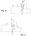
- FIG. 3 schematically represents the needle of FIG. 2 in the phase of another descent, with the means for removing the mesh approached at the head of the needle, that is to say in the cover position, and with the knitted mesh of the respective flap;
- FIG. 4 represents yet another downside, with the means for removing the mesh advanced with respect to the previous phase and with the mesh invested on them:
- FIG. 5 shows the needle of FIG. 4, with the removal means raised with respect to the previous phase and release of the respective plate, and means for supporting the mesh invested on the aforementioned removal means;
- Fig. 6 schematically represents the means for removing and transferring the mesh, in accordance with an alternative embodiment;
- FIG. 7 schematically represents the means for removing the mesh, with the support means of the same, and the means (13) for transferring the mesh from the respective removal means to a needle (10) of the same machine or of a another textile machine, in the initial phase of depositing or unloading the mesh;
- Fig. 8 represents the means of FIG. 7 in the deposited mesh position;
- Fig. 9 schematically represents the means for removing and transferring the mesh of FIG. 7, in the initial phase of depositing the mesh on a stitching point (11);
- Fig. 10 shows the means of FIG. 9, in the deposited mesh position;
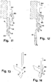
- Fig. 11 schematically represents the means for removing the mesh, according to an alternative embodiment, placed in the mesh retaining position;
- Fig. 12 shows the means of FIG.
- Fig. 13 schematically represents the means for removing the mesh, in accordance with a form alternative embodiment, in retained mesh position;
- Fig. 14 shows the means of FIG. 13, in the initial release phase of the mesh;
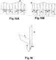
- Fig. 15A schematically represents a group of sampling devices of a length between two different values;
- Fig. 15B schematically represents a group of sampling organs. different length between three different values;
- Fig. 16 shows the means of FIG. 13 in the final phase of predisposition of the same to the release of the mesh;
- Fig. 17 schematically represents the means for removing and supporting the mesh with the respective support members;
- Fig. 18 schematically represents the means for removing the mesh with the respective movement members, according to a first embodiment;
- Fig. 15A schematically represents a group of sampling devices of a length between two different values
- Fig. 15B schematically represents a group of sampling organs. different length between three different values
- Fig. 16 shows the means of FIG. 13 in the final phase of pre
- FIG. 19 schematically represents the means for removing the mesh with the respective movement members, according to another embodiment
- Fig. 20 schematically represents the means used to control the means of FIG. 16
- Fig. 21 schematically represents a group of sampling members with means of movement in two directions orthogonal to each other.
- the device for carrying out said operational process comprises cam means, per se already known, for the movement of said needles (1), and further comprises means for the removal and transfer of said meshes (3), one by one, with a fundamentally flat element (6), called “punch", for each mesh (3) to be sampled and transferred, which is below provided with a groove (60) with a concavity fundamentally turned towards the head of a needle (1) loaded with the mesh (3) to allow the narrow approach to the hook of the needle (1) corresponding so as to achieve the cover of the needle (1) and the element (6) by closing the valve (5): said punch (6) being expediently supported by a member (61) to which it is connected so as to result in fixed or otherwise longitudinally sliding action against it.
- each of the punches (6) is provided with a heel (64) slaved to an external control organ for activate the movement, such as a cam (63) or a control bar (65) to obtain the movement of the punches (6) in sequence or all together.
- the downward movement of the punch (6) can be exploited to obtain the corresponding lowering of the respective needle (1) after contact between the punch (6) and the needle (1).
- Each punch (6) can be provided with any member for interfacing the punch with a corresponding control member.
- the distance between two adjacent punches (6) is equal to the pitch or center distance between said needles (1) or a multiple of said pitch.
- Said punches (6) are all of the same length or of a different length, in relation to the type of processing of the meshes (3) to be executed. More precisely, with reference to FIGS. 15A and 15B of the appended drawings, if intended to carry out the simultaneous removal of all the meshes (3) of the manufactured product, said punches (6) are all of the same length, so that the respective ends free (7), that is to say those intended for the coupling of cover with the respective needles (1), always result at the same level with respect to the felling plane (4) of the machine.
- the punches (6) adjacent to each other are of a different length, so that the free ends (7) of the punches (6) operating the removal meshes (3) result at a different level, compared to the felling plane (4) of the machine, from that of the other punches (6) of the group. This avoids an'eccessive expansion of the meshes (3) thus treated.
- said punches (6) are fixed to the support (61).
- the movement of the punches (6) is obtained with the corresponding movement of the support (61), which is actionable, in turn, by means of producing cylinders and guided on corresponding or similar rails.
- said punches (6) are housed one by one in corresponding fundamentally rectilinear grooves (62) of the support (61), so as to allow bidirectional movement in the respective longitudinal direction relative to the support (61).
- the movement of the punches (6) relative to the support (61) is obtainable with cam means (63) or with a control bar (65), acting on the relative heels (64) or equivalent bodies, according to whether one wishes to carry out the movement of the punches (6) one by one, in sequence, or their simultaneous translation from and to the textile head of the machine.
- said grooves (62) can have different shape and development from those illustrated in the figures of the accompanying drawings.
- the movement of the punches (6) for carrying out the removal and transfer of the meshes (3) is achievable by combining the movement of the support (61), for the displacements of major amplitude, with that of the punches (6) relative to the support (61), for displacements of minor amplitude. In this way it is also possible to differentiate the relative displacements between the different punches of the support and / or to select the punches to be moved.
- said support (61) is subdivided into several separate sections, each of which with a predetermined number of punches (6), so as to further differentiate the movement of the punches (6) of the device and thus enlarge subsequently the range of mesh withdrawals (3) that can be carried out, in order to obtain a greater number of possible machining operations.
- Each of said punches (6) can also be shaped so as to present a rod with the axis inclined relative to the portion of the anterior end (7), as illustrated in Figg. 13 and 14 of the accompanying drawings.
- means are provided for retaining each of said meshes (3) in a fixed and predetermined position on the corresponding punch (6).
- Said means are shaped, according to a first embodiment, by a recess (9) which is provided on each of said punches (6) at a predetermined distance from the respective free end (7) and it is intended to retain the corresponding mesh (3) removed by the effect of the inherent elasticity of this one.
- said means for retaining the mesh (3) on the punch (6) are formed by a blade (8) placed, on command, below the mesh (3) invested on the respective punch (6) so as to prevent spontaneous release.
- Said blade (8) can be associated with a corresponding control member which consists, for example, of a pile (80) intended to cause rotation thereof around a pivot (81) for connecting the blade (8 ) to a corresponding support member (82).
- the function performed by the aforementioned pile (80) can otherwise be performed by a cam pivoting about an axis parallel to that of the punch (6), or by a realizing cylinder, acting on the blade (8). This makes it possible to prevent the fabric from slipping out of the punches (6) during the mesh transfer operations (3). Means are also advantageously provided for releasing each mesh (3) from the respective punch (6).
- Said mesh release means (3) consist, according to a first embodiment, by a flat element (13) acting on the mesh (3) invested on the punch (6), so as to cause the movement thereof. pushed towards the free end of the punch (6), and thus the transfer to the textile member where it is intended, such as for example the needle (10) or the tip (11) illustrated in the figures of the appended drawings.
- a pile (12) pivoting around a pivot (92) for connecting the pile (12) is provided.
- said mesh release means (3) consist of a pile with a basically straight axis (14) in the free end is intended to slide adjacent to the corresponding end of the punch (6), which is conveniently shaped with a rectilinear groove (96) to allow the approach of the pile (14) so as to provide the covering, respectively the uncovering, of the respective recess (9) and so as to be inserted inside the mesh (3) by expanding it, thus allowing unloading.
- the free end of said pile (14) is wedge-shaped and folded laterally so as to result oriented towards the punch (6).
Landscapes
- Engineering & Computer Science (AREA)
- Textile Engineering (AREA)
- Treatment Of Fiber Materials (AREA)
- Knitting Machines (AREA)
- Chemical Or Physical Treatment Of Fibers (AREA)
Abstract
Description
La presente invention concerne un procédé et un dispositif pour le prélèvement d'une ou plusieurs mailles d'un produit manufacturé tricoté, des aiguilles de tissage d'une machine textile et pour leur transfert et placement sur d'autres organes textiles, de la même machine ou d'une autre.The present invention relates to a method and a device for removing one or more stitches from a knitted manufactured product, weaving needles of a textile machine and for their transfer and placement on other textile organs, in the same way machine or another.
Il est connu par les hommes du metiér que dans les machines textiles à tricoter, plus particulièrement les machines rectilignes, par exemple dans les métiers à tisser du type Cotton, pour permettre la réalisation de différentes opérations de tricotage après la réalisation d'un produit manufacturé en tricot, comme par exemple le tricotage de deux parties différentes d'un même produit manufacturé, les mailles formées en dernier, ou une partie d'entre elles, sont prélèvées par les respectives aiguilles de formation au moyen d'organes, en jargon appelés "poinçons", aptes à couvrir lesdites aiguilles de manière à permettre le transfert des mailles de ces-ci aux poinçons. Les mailles ainsi prélèvées sont donc transférées, avec lesdits poinçons, sur d'autres aiguilles de la même machine ou d'une machine différente. Avec le terme "couverture" on conçoit une condition conçue par un accouplement momentané entre la tête d'un poinçon et celle d'une aiguille, l'un sur le prolongement de l'autre, sans solution de continuité, telle de permettre le transfert d'une maille de l'aiguille au poinçons, et/ou vice versa, sans obstacle.It is known by those skilled in the art that in textile knitting machines, more particularly rectilinear machines, for example in weaving looms of the Cotton type, to allow the carrying out of different knitting operations after the production of a manufactured product. in knitting, such as for example the knitting of two different parts of the same manufactured product, the stitches formed last, or a part of them, are taken up by the respective training needles by means of organs, in jargon called "punches", capable of covering said needles so as to allow the transfer of the meshes from these to the punches. The meshes thus taken are therefore transferred, with said punches, to other needles of the same machine or of a different machine. With the term "cover" we conceive a condition conceived by a momentary coupling between the head of a punch and that of a needle, one on the extension of the other, with no solution of continuity, such as to allow transfer of a needle stitch to the punches, and / or vice versa, without obstacle.
Lesdits poinçons sont en nombre pair au nombre des aiguilles de tissage chargées des mailles à prélèver, façonnés de manière à pouvoir être accrochés par la tête au crochet des aiguilles, et regroupés en bloques, habituellement appellés "peignes", chacun desquels comprend un nombre prédetérminé de poinçons.
Mais le mouvement desdits peignes est très difficile et le plus souvent manuelle, ce-ci requiért une bonne expérience dans la manipulation de ces organes textiles, et donc requiért l'emploi de main-d'oeuvre spécialisée et comporte un coût élevé de fabrication du produit terminé. En outre leur application aux machines circulaires est difficile à réaliser vu la complexité de gestion des organes mécaniques necessaires au déroulement automatique desdites opérations.Said punches are in an even number to the number of weaving needles loaded with the meshes to be taken, shaped so as to be able to be hooked by the head on the hook of the needles, and grouped in blocks, usually called "combs", each of which comprises a predetermined number punches.
But the movement of said combs is very difficult and most often manual, it requires good experience in handling these textile organs, and therefore requires the use of specialized labor and involves a high cost of manufacturing the finished product. In addition, their application to circular machines is difficult to achieve given the complexity of managing the mechanical organs necessary for the automatic conduct of said operations.
Le but principale de la presente invention est celui d'éliminer lesdits inconvenients.The main purpose of the present invention is to eliminate said drawbacks.
A ce resultat on est parvenus, conformément à l'invention, en adoptant un procédé opérationnel comprenant une phase préparatoire de fabbrication d'un produit manufacturé tricoté avec une machine pourvue de plusieurs aiguilles de tricotage automatiques, particulierement du type à clapet ou à coulisse et d'un plan d'abattage des mailles, lequel comporte, pour chaque maille du produit manufacturé qui faut prélèver et transférer, les suivantes phases opérationnelles:
- soulever l'aiguille de tissage qui supporte la maille, de manière à la placer en position de déchargé sur l'aiguille, c'est-à-dire inférieurement au clapet ou coulisse dans sa position ouverte;
- abaisser l'aiguille ainsi soulevée, de manière à obliger ladite maille à se placer sur le plan d'abattage de la machine et, avec un'autre descente de l'aiguille, obliger la maille à se placer sur le cou de celle-ci en se plaçant en proximité du respectif clapet ou de la coulisse en position ouverte;
- abaisser ultérieurement ladite aiguille, de manière à provoquer la fermeture du clapet respectif ou l'actionnemmnt de la coulisse sur la tête de l'aiguille par la même maille et, avant de la complète fermeture du clapet, ou de l'actionnement de la coulisse, de l'aiguille, raprocher un élément de prélèvement de la maille à la tête de l'aiguille jusqu'à son contact avec celle-ci, de manière à réaliser sa couverture et celle de l'organe de prélèvement au moment de la fermeture dudit clapet ou coulisse;
- abaisser encore ladite aiguille et, ensemble, ledit élément de prélèvement de la maille, de manière à l'insérer à l'intérieur de la même et ainsi obtenir le transfert automatique de ladite aiguille sur l'élément de prélèvement;
- transférer ailleur la maille ainsi prélèvée, par exemple la déposer sur une aiguille ou autre organe de la même machine ou d'une autre machine textile.
- lift the weaving needle which supports the mesh, so as to place it in the unloaded position on the needle, that is to say below the valve or slides in its open position;
- lower the needle thus raised, so as to force said stitch to be placed on the felling plane of the machine and, with another descent of the needle, oblige the stitch to be placed on the neck thereof by placing themselves near the respective valve or slide in the open position;
- subsequently lower said needle so as to cause the closure of the respective valve or the actuation of the slide on the head of the needle by the same mesh and, before complete closure of the valve, or actuation of the slide , of the needle, close a sampling element of the mesh at the head of the needle until it contacts it, so as to provide cover and that of the sampling organ at the time of closing said valve or slide;
- further lowering said needle and, together, said sampling element of the stitch, so as to insert it inside the same and thus obtain the automatic transfer of said needle onto the sampling element;
- transfer the mesh thus removed elsewhere, for example deposit it on a needle or other member of the same machine or of another textile machine.
Avantageusement, conformément à l'invention, le nombre des mailles ainsi prélèvées est indifférent, de façon compatible avec les caractéristiques structurales du produit manufacturé et de la machine textile préposée à sa formation: ledites mailles peuvent en outre être prélèvées par groupes de mailles adjacentes, chacun groupe étant formé par un nombre prédéterminé de mailles.Advantageously, in accordance with the invention, the number of meshes thus removed is indifferent, in a manner compatible with the structural characteristics of the manufactured product and of the textile machine in charge of its formation: said meshes can also be sampled by adjacent mesh groups, each group being formed by a predetermined number of meshes.
Pour ce qu'il concerne la réalisation dudit procédé opérationel, il comprend, en combinaison: - des moyens por le mouvement de chacune desdites aiguilles de formation des mailles dans la direction du respectif axe longitudinal;
- des moyens pour le prélèvement des mailles desdites aiguilles et pour leur transfert sur d'autres organes textiles de la même machine ou d'une autre machine textile;
- des moyens pour le mouvement desdits moyens de prélèvement et transfert des mailles.
- means for removing the stitches from said needles and for transferring them to other textile members of the same machine or of another textile machine;
- means for the movement of said means for removing and transferring meshes.
Les avantages qui dérivent de la presente invention consistent essentiellement en ce que il est possible opérer le prélèvement et le transfert de toutes les mailles ou d'une partie d'entre elles d'un produit manufacturé entre organes textiles d'une même machine, ou de machines différentes, de manière complètement automatique et avec une production sensiblement plus importante de celle obtenue avec des appareillages traditionaux, ce qu'il permet de réduire de façon draconienne le coût de fabrication des produits finis; qu'un procédé opérationnel conformément à l'invention est réalisable soit avec des machines rectilignes, que avec des machines circulaires ou mixtes; qu'un dispositif conformément à l'invention est de fabrication relativement simple, économique et fiable même après un temps prolongé d'utilisation.The advantages deriving from the present invention essentially consist in the fact that it is possible to operate the removal and transfer of all the meshes or of a part of them of a manufactured product between textile organs of the same machine, or different machines, completely automatically and with a production significantly higher than that obtained with traditional equipment, which allows to drastically reduce the cost of manufacturing finished products; that an operational process according to the invention is achievable either with rectilinear machines, than with circular or mixed machines; that a device according to the invention is relatively simple, economical and reliable to manufacture even after an extended period of use.
Ces avantages et caractéristiques de l'invention ainsi que d'autres seront plus et mieux compris de chaque homme du métier à la lumière de la description qui va suivre et à l'aide des dessins annexés donnés à titre d'exemplification pratique d'une forme concrète de réalisation, mais à ne pas considérer dans le sens limitatif, sur lesquels: la Fig. 1 représente schématiquement le détail d'une machine textile prédisposée pour permettre le prélèvement et le transfert des mailles d'un produit manufacturé tricoté conformément à l'invention, ladite machine étant du type à platines (2) mobiles, où est visible une aiguille de tissage du type à clapet au terme de la phase de son soulevement, dans la position à platines fermées et avec la respective maille in position de déchargé; la Fig. 2 représente l'aiguille de la Fig. 1 dans la phase de déscente, avec la correspondante maille (3) en proximité de la charnière du relatif clapet; la Fig. 3 représente schématiquement l'aiguille de la Fig. 2 dans la phase d'une autre déscente, avec les moyens de prélèvement de la maille approchée à la tête de l'aiguille, c'est-à-dire en position de couverture, et avec la maille à cheval de respectif clapet; la Fig. 4 représente encore une autre déscente, avec les moyens de prélèvement de la maille avancés par rapport à la phase précéndente et avec la maille investie sur eux: la Fig. 5 représente l'aiguille de la Fig. 4, avec les moyens de prélèvement soulevés par rapport à la phase précèdente et de dégagement de la respective platine, et des moyens de soutien de la maille investie sur les précités moyens de prélèvement; la Fig. 6 représente schématiquement les moyens de prélèvement et transfert de la maille, conformément à une forme alternative de réalisation; la Fig. 7 représente schématiquement les moyens de prélèvement de la maille, avec les moyens de soutien de la même, et les moyens (13) de transfert de la maille des respectifs moyens de prélèvement à une aiguille (10) de la même machine ou d'une autre machine textile, dans la phase initiale de dépôt ou déchargement de la maille; la Fig. 8 représente les moyens de la Fig. 7 en position de maille déposée; la Fig. 9 représente schématiquement les moyens de prélèvement et transfert de la maille de la Fig. 7, dans la phase initiale de dépôt de la maille sur une pointe de remailleuse (11); la Fig. 10 représente les moyens de la Fig. 9, en position de maille déposée; la Fig. 11 représente schématiquement les moyens de prélèvement de la maille, selon une forme alternative de réalisation, placés en position de retenue de la maille; la Fig. 12 représente les moyens de la Fig. 11 en position de libération consentie de la maille; la Fig. 13 représente schématiquement les moyens de prélèvement de la maille, conformément à une forme alternative de réalisation, en position de maille retenue; la Fig. 14 représente les moyens de la Fig. 13, en phase initiale de libération consentie de la maille; la Fig. 15A représente schématiquement un groupe d'organes de prélèvement d'une longuer comprise entre deux valeurs différentes; la Fig. 15B représente schématiquement un groupe d'organes de prélèvement. de longuer différente comprise entre trois valeurs différentes; la Fig. 16 représente les moyens de la Fig. 13 dans la phase finale de prédisposition des mêmes à la libération de la maille; la Fig. 17 représente schématiquement les moyens de prélèvement et de soutien de la maille avec les respectifs organes de soutien; la Fig. 18 représente schématiquement les moyens de prélèvement de la maille avec les respectifs organes de mouvement, selon une première forme de réalisation; la Fig. 19 représente schématiquement les moyens de prélèvement de la maille avec les respectifs organes de mouvement, selon un'autre forme de réalisation; la Fig. 20 représente schématiquement les moyens préposés à la commande des moyens de la Fig. 16; la Fig. 21 représente schématiquement un groupe d'organes de prélèvement avec des moyens de mouvement selon deux directions orthogonales entre elles.These advantages and characteristics of the invention as well as others will be more and better understood by each person skilled in the art in the light of the description which follows and with the aid of the appended drawings given by way of practical example of a concrete embodiment, but not to be considered in the limiting sense, on which: FIG. 1 schematically shows the detail of a textile machine predisposed to allow the removal and transfer of the meshes of a knitted manufactured product in accordance with the invention, said machine being of the type with mobile plates (2), where a needle is visible weaving of the valve type at the end of the lifting phase, in the position with closed plates and with the respective mesh in the unloaded position; Fig. 2 represents the needle of FIG. 1 in the descent phase, with the corresponding mesh (3) near the hinge of the relative valve; Fig. 3 schematically represents the needle of FIG. 2 in the phase of another descent, with the means for removing the mesh approached at the head of the needle, that is to say in the cover position, and with the knitted mesh of the respective flap; Fig. 4 represents yet another downside, with the means for removing the mesh advanced with respect to the previous phase and with the mesh invested on them: FIG. 5 shows the needle of FIG. 4, with the removal means raised with respect to the previous phase and release of the respective plate, and means for supporting the mesh invested on the aforementioned removal means; Fig. 6 schematically represents the means for removing and transferring the mesh, in accordance with an alternative embodiment; Fig. 7 schematically represents the means for removing the mesh, with the support means of the same, and the means (13) for transferring the mesh from the respective removal means to a needle (10) of the same machine or of a another textile machine, in the initial phase of depositing or unloading the mesh; Fig. 8 represents the means of FIG. 7 in the deposited mesh position; Fig. 9 schematically represents the means for removing and transferring the mesh of FIG. 7, in the initial phase of depositing the mesh on a stitching point (11); Fig. 10 shows the means of FIG. 9, in the deposited mesh position; Fig. 11 schematically represents the means for removing the mesh, according to an alternative embodiment, placed in the mesh retaining position; Fig. 12 shows the means of FIG. 11 in the released position of the mesh; Fig. 13 schematically represents the means for removing the mesh, in accordance with a form alternative embodiment, in retained mesh position; Fig. 14 shows the means of FIG. 13, in the initial release phase of the mesh; Fig. 15A schematically represents a group of sampling devices of a length between two different values; Fig. 15B schematically represents a group of sampling organs. different length between three different values; Fig. 16 shows the means of FIG. 13 in the final phase of predisposition of the same to the release of the mesh; Fig. 17 schematically represents the means for removing and supporting the mesh with the respective support members; Fig. 18 schematically represents the means for removing the mesh with the respective movement members, according to a first embodiment; Fig. 19 schematically represents the means for removing the mesh with the respective movement members, according to another embodiment; Fig. 20 schematically represents the means used to control the means of FIG. 16; Fig. 21 schematically represents a group of sampling members with means of movement in two directions orthogonal to each other.
Réduit à sa structure essentielle et en référence aux figures des dessins annexés, un procédé pour le prélèvement d'une ou plusieurs mailles d'un produit manufacturé par des aiguille dei tricotage d'une machine textile et pour leur transfert et dépôt sur d'autres organes textiles, de la même ou d'une autre machine, comprenant la phase préliminaire de fabriquer un produit manufacturé tricoté avec une machine pourvue de plusieurs aiguilles de tricotage (1) du type à clapet et d'un plan d'abattage (4) des mailles (3), conformément à l'invention comporte, pour chaque maille (3) du produit manufacturé à prélèver et transférer, les suivantes phases opérationnelles:
- (a) soulever l'aiguille (1) de tricotage qui supporte la maille (3), avec les platines (2) avancées, c'est-à-dire fermées, de manière à placer la maille (3) en position de déchargé (niveau S de la Fig. 1), c'est-à-dire inférieurement au clapet (5) ouvert de l'aiguille (1);
- (b) abaisser ladite aiguille (1), de manière à obliger la maille (3) à se placer sur le plan d'abatage (4), lequel est délimité dans ce cas par les platines (2) et, avec une autre déscente de l'aiguille (1), obliger la maille (3) à bouger sur le cou de l'aiguille (1) en se plaçant en proximité de la charnière du respectif clapet (5);
- (c) abaisser encore ladite aiguille (1), de manière à provoquer la fermeture du respectif clapet (5) du côté de la même maille (3) investie sur ladite maille, laquelle ne peut glisser ensemble à l'aiguille (1) puisque elle est appuiée sur le plan (4) d'abattage, et, avant la complète fermeture du clapet (5), raprocher un élément (6) de prélèvement de la maille à la tête dell'aiguille (1) jusqu'à son contact avec celle-ci, de manière à réaliser la couverture de l'aiguille (1) et dudit élément (6) avec le clapet ainsi mouvementé;
- (d) abaisser ultérieurement l'aiguille (1) et ledit élément (6), de manière à insérer cette dernière à l'intérieur de la maille (3), et ainsi en obtenir le transfet automatique de l'aiguille (1) sur l'élément (6);
- (e) transférer ailleur la maille (3) ainsi prélèvée, de manière à permettre des traitements successifs, comme par exemple la poursuite du tricotage du produit manufaturé sur un'autre machine ou sur un'aiguille d'une différente fonture de la même machine ou sur un'autre zone de la même fonture d'aiguilles, ou le positionnement de la maille à une distance prédéterminée de l'aiguille (1) en attente, et permettre la poursuite du tricotage, ou la mise en train d'un cycle successif de façonnage, sur l'aiguille (1) libérée de la maille (3).
- (a) raise the knitting needle (1) which supports the mesh (3), with the plates (2) advanced, that is to say closed, so as to place the mesh (3) in the unloaded position (level S of FIG. 1), that is to say below the valve (5) open to the needle (1);
- (b) lower said needle (1), so as to force the mesh (3) to be placed on the felling plane (4), which is in this case delimited by the plates (2) and, with another descent of the needle (1), force the stitch (3) to move on the neck of the needle (1) by placing itself near the hinge of the respective valve (5);
- (c) further lowering said needle (1), so as to cause the closure of the respective valve (5) on the side of the same stitch (3) invested on said stitch, which cannot slide together with the needle (1) since it is supported on the felling plane (4), and, before the valve is completely closed (5), attach an element (6) for removing the mesh from the needle head (1) until it contacts with it, so as to achieve the covering the needle (1) and said element (6) with the valve thus actuated;
- (d) subsequently lower the needle (1) and said element (6), so as to insert the latter inside the mesh (3), and thus obtain the automatic transfer of the needle (1) to the element (6);
- (e) transfer the mesh (3) thus taken elsewhere, so as to allow successive treatments, such as for example the continued knitting of the manufatured product on another machine or on a needle of a different needle bed of the same machine or on another zone of the same needle bed, or the positioning of the stitch at a predetermined distance from the waiting needle (1), and allow the continuation of knitting, or the setting in motion of a cycle successive shaping, on the needle (1) released from the mesh (3).
Il va de soi que lesdites opérations peuvent être répetées plusieurs fois, de manière que un même élément (6) peut prélèver plusieurs mailles (3) en succession. Après les mailles (3) ainsi prélèvées peuvent être dirigées à des façonnages successifs. De tel façon, il est possible par exemple prélèver les mailles (3) terminales de deux ou plusieurs produits manufacturés, ou d'une ou plusieurs parties de produits manufacturés, pour les transférer sur une machine à remailler et en effectuer l'assemblage, ou pour les transférer sur une autre machine textile pour en poursuivre le tricotage au moyen de cette dernière.It goes without saying that said operations can be repeated several times, so that the same element (6) can take several meshes (3) in succession. After the meshes (3) thus removed can be directed to successive shapings. In this way, it is possible, for example, to take off the terminal meshes (3) of two or more manufactured products, or of one or more parts of manufactured products, to transfer them to a re-stitching machine and to assemble them, or to transfer them to another textile machine to continue the knitting using the latter.
Conformément à l'invention il est possible réaliser le traitement sur-mentionné d'un quelconque nombre de mailles (3) du produit manufacturé, selon les caracteristiques élastiques et dimensionnelles des mailles (3). Dans le cas de prélèvement de toutes les mailles on obtient le prélèvement et le transfert du produit manufacturé entier. Les mailles (3) peuvent être ainsi prélèvées et transférées même par groupes, chaque groupe comprendant un nombre prédéterminé de mailles (3). Avantageusement, conformément à l'invention, il est prevu d'opérer l'éloignement de la maille (3) de ladite aiguille (1) en opérant avant la retenue de la maille (3) en position fixe et prédéterminée sur lesdits moyens (6), pour en empêcher la libération spontanée.In accordance with the invention it is possible to carry out the above-mentioned treatment of any number of meshes (3) of the manufactured product, according to the elastic and dimensional characteristics of the meshes (3). In the case of removal of all meshes, the removal and transfer of the entire manufactured product is obtained. The meshes (3) can thus be removed and transferred even in groups, each group comprising a predetermined number of meshes (3). Advantageously, in accordance with the invention, it is planned to operate the removal of the mesh (3) from said needle (1) by operating before the retention of the mesh (3) in a fixed and predetermined position on said means (6 ), to prevent spontaneous release.
Avantageusement, conformément à l'invention et en référence aux Figg. 8 et 9 des dessins annexés, successivemnt à ladite phase (e) d'éloignement de la maille (3) de l'aiguille correspondante (1) il est prevu d'opérer les suivantes autres phases opérationnelles:
- mouvementer lesdits moyens (6) de manière à placer la maille (3) au-dessus de la tête d'une aiguille (10) différente de celle du départ (1). Ladite aiguille (10) peut être, par exemple, du type à clapet, à coulisse ou à bec;
- libérer la maille (3) desdits moyens (6) et l'investir sur le cou de l'aiguille (10).
- moving said means (6) so as to place the stitch (3) above the head of a needle (10) different from that of the start (1). Said needle (10) can be, for example, of the valve, slide or beak type;
- release the stitch (3) from said means (6) and invest it on the neck of the needle (10).
Avantageusement, conformément à l'invention et en référence aux Figg. 9 et 10 des dessins annexés, successivement à ladite phase (e) d'éloignement de la maille (3) de l'aiguille (1), il est prevu de déposer la maille (3) sur une pointe de remaillage (11), par exemple pour le finissage des mailles terminales du produit manufacturé, ou pour l'union de deux ou plusieurs parties de produits manufacturés tricotés, ou moyen du remaillage.Advantageously, in accordance with the invention and with reference to Figg. 9 and 10 of the appended drawings, successively to said phase (e) of moving the mesh (3) away from the needle (1), it is planned to deposit the mesh (3) on a remeshing point (11), for example for the finishing of the final stitches of the manufactured product, or for the union of two or more parts of knitted manufactured products, or by means of remeshing.
Pour ce qu'il concerne le dispositif pour la réalisation dudit procédé opérationnel, il comprend des moyens à came, en soi déjà connus, pour le mouvement desdites aiguilles (1), et en outre comprend des moyens pour le prélèvement et le transfert desdites mailles (3), une par une, avec un élément (6) fondamentalement plat, appellés "poinçon", pour chaque maille (3) à prélèver et transférer, lequel est inférieurement pourvu d'une gorge (60) avec une concavité fondamentallement retournée vers la tête d'une aiguille (1) chargée de la maille (3) pour en permettre l'etroit approchement au crochet de l'aiguille (1) correspondante de manière à réaliser la couverture de l'aiguille (1) et de l'élément (6) par la fermeture du clapet (5): ledit poinçon (6) étant opportunement supporté par un organe (61) auquel est lié de manière à resulter fixe ou autrement longitudinalement coulissant par rappot à celui-ci. Avantageusement, conformément à l'invention, chacun des poinçons (6) est pourvu d'un tallon (64) asservis à un organ extérieur de commande pour en activer le mouvement, comme par exemple une came (63) ou une barre de commande (65) pour obtenir le mouvement des poinçons (6) en sequence ou tous ensemble. Le mouvement vers le bas du poinçon (6) peut être exploité pour obtenir l'abbaissement correspondant de la respective aiguille (1) après le contact entre le poinçon (6) et l'aiguille (1). Chaque poinçon (6) peut être pourvu d'un quelconque organe d'interface du poinçon avec un organe de commande correspondant.As regards the device for carrying out said operational process, it comprises cam means, per se already known, for the movement of said needles (1), and further comprises means for the removal and transfer of said meshes (3), one by one, with a fundamentally flat element (6), called "punch", for each mesh (3) to be sampled and transferred, which is below provided with a groove (60) with a concavity fundamentally turned towards the head of a needle (1) loaded with the mesh (3) to allow the narrow approach to the hook of the needle (1) corresponding so as to achieve the cover of the needle (1) and the element (6) by closing the valve (5): said punch (6) being expediently supported by a member (61) to which it is connected so as to result in fixed or otherwise longitudinally sliding action against it. Advantageously, in accordance with the invention, each of the punches (6) is provided with a heel (64) slaved to an external control organ for activate the movement, such as a cam (63) or a control bar (65) to obtain the movement of the punches (6) in sequence or all together. The downward movement of the punch (6) can be exploited to obtain the corresponding lowering of the respective needle (1) after contact between the punch (6) and the needle (1). Each punch (6) can be provided with any member for interfacing the punch with a corresponding control member.
Avantageusement, conformément à l'invention, la distance entre deux poinçons (6) adjacents est égale au pas ou entraxe entre lesdites aiguilles (1) ou un multiple dudit pas.
Lesdits poinçons (6) sont tous de la même longuer ou d'une longuer différente, en relation au type de traitement des mailles (3) à executer. Plus precisement, en référence aux figures 15A et 15B des dessins annexés, si destinés à executer le prélèvement simultané de toutes les mailles (3) du produit manufacturé, lesdits poinçons (6) sont tous de la même longuer, de manière que les respectives extrémitées libres (7), c'est-à-dire celles destinées à l'accouplement de couverture avec les respectives aiguilles (1), resultent toujour à un même niveau par rapport au plan d'abattage (4) de la machine. Si destinés à ne pas opérer le prélèvement simultané des mailles (3) adjacentes, les poinçons (6) adjacents entre eux sont d'une longuer différente, de manière que l'extrémitées libres (7) des poinçons (6) opérants le prélèvement des mailles (3) resultent à un niveau différent, par rapport au plan d'abattage (4) de la machine, de celle des autres poinçons (6) du groupe. Ce-ci permet d'éviter un'eccessive dilatation des mailles (3) ainsi traitées.Advantageously, according to the invention, the distance between two adjacent punches (6) is equal to the pitch or center distance between said needles (1) or a multiple of said pitch.
Said punches (6) are all of the same length or of a different length, in relation to the type of processing of the meshes (3) to be executed. More precisely, with reference to FIGS. 15A and 15B of the appended drawings, if intended to carry out the simultaneous removal of all the meshes (3) of the manufactured product, said punches (6) are all of the same length, so that the respective ends free (7), that is to say those intended for the coupling of cover with the respective needles (1), always result at the same level with respect to the felling plane (4) of the machine. If intended not to operate the simultaneous removal of the meshes (3) adjacent, the punches (6) adjacent to each other are of a different length, so that the free ends (7) of the punches (6) operating the removal meshes (3) result at a different level, compared to the felling plane (4) of the machine, from that of the other punches (6) of the group. This avoids an'eccessive expansion of the meshes (3) thus treated.
Selon une première forme de réalisation de l'invention, lesdits poinçons (6) sont fixes au support (61). Dans ce cas, le mouvement des poinçons (6) est obtenu avec le mouvement correspondant du support (61), lequel est actionable, à son tour, au moyen de cylindres réalisateurs et guidé sur des railles correspondantes ou du même genre.
Conformément à une deuxième forme de réalisation de l'invention, lesdits poinçons (6) sont logés un par un dans des gorges correspondantes fondalmentelement rectilignes (62) du support (61), de manière à en permettre le mouvement bidirectional dans la respective direction longitudinale par rapport au support (61). Dans ce cas, le mouvement des poinçons (6) par rapport au support (61) est obtenible avec des moyens à came (63) ou avec une barre de commande (65), agissants sur les relatifs tallons (64) ou organes equivalents, selon qu'on veuille réaliser le mouvement des poinçons (6) un par un, en sequence, ou leur translation simultanée de et vers la tête textile de la machine. De toutes les manières, lesdites gorges (62) peuvent avoir forme et dévelloppement différents de ces illustrés dans les figures des dessins annexés.According to a first embodiment of the invention, said punches (6) are fixed to the support (61). In this case, the movement of the punches (6) is obtained with the corresponding movement of the support (61), which is actionable, in turn, by means of producing cylinders and guided on corresponding or similar rails.
According to a second embodiment of the invention, said punches (6) are housed one by one in corresponding fundamentally rectilinear grooves (62) of the support (61), so as to allow bidirectional movement in the respective longitudinal direction relative to the support (61). In this case, the movement of the punches (6) relative to the support (61) is obtainable with cam means (63) or with a control bar (65), acting on the relative heels (64) or equivalent bodies, according to whether one wishes to carry out the movement of the punches (6) one by one, in sequence, or their simultaneous translation from and to the textile head of the machine. In any case, said grooves (62) can have different shape and development from those illustrated in the figures of the accompanying drawings.
Dans le cas des poinçons (6) mobiles par rapport audit support (61), le mouvement des poinçons (6) pour effectuer le prélèvement et le transfert des mailles (3) est réalisable en combinant le mouvement du support (61), pour les déplacements d'amplitude majeure, avec celui des poinçons (6) par rapport au support (61), pour les déplacements d'amplitude mineure. De cette manière il est possible aussi différencier les déplacements relatifs entre les differents poinçons du support et/ou selectioner les poinçons à mouvementer.In the case of the punches (6) movable relative to said support (61), the movement of the punches (6) for carrying out the removal and transfer of the meshes (3) is achievable by combining the movement of the support (61), for the displacements of major amplitude, with that of the punches (6) relative to the support (61), for displacements of minor amplitude. In this way it is also possible to differentiate the relative displacements between the different punches of the support and / or to select the punches to be moved.
Avantageusement, conformément à l'invention, ledit support (61) est subdivisé en plusieurs sections distinctes, chacune desquelles avec un nombre prédéterminés de poinçons (6), de manière à différencier encore plus le mouvement des poinçons (6) du dispositif et ainsi agrandir ultérieurement la gamme des prélèvements de mailles (3) effectuables, au fin d'obtenir un plus grand nombre d'usinages possibles.
Chacun desdits poinçons (6) peut être aussi façonné de manière à presenter une tige avec l'axe incliné par rapport à la portion de l'extrémité antérieure (7), comme illustré dans les Figg. 13 et 14 des dessins annexés.Advantageously, in accordance with the invention, said support (61) is subdivided into several separate sections, each of which with a predetermined number of punches (6), so as to further differentiate the movement of the punches (6) of the device and thus enlarge subsequently the range of mesh withdrawals (3) that can be carried out, in order to obtain a greater number of possible machining operations.
Each of said punches (6) can also be shaped so as to present a rod with the axis inclined relative to the portion of the anterior end (7), as illustrated in Figg. 13 and 14 of the accompanying drawings.
Avantageusement, conformément à l'invention, des moyens sont prevus pour retenir chacune desdites mailles (3) en position fixe et prédéterminée sur le poinçon correspondant (6). Lesdits moyens sont façonnés, selon une première forme de réalisation, par un'évidure (9) laquelle est prevue sur chacun desdits poinçons (6) à une distance prédéterminée de la respective extrémité libre (7) et elle est destinée à retenir la correspondante maille (3) prélèveée par effet de l'elasticité propre de celle-ci. Alternativement, lesdits moyens de retenue de la maille (3) sur le poinçon (6) sont formés d'une lame (8) placée, à commande, inférieurement à la maille (3) investie sur le respectif poinçon (6) de manière à en empêcher la libération spontanée. Ladite lame (8) on peut l'associer à un organe correspondant de commande lequel est constitué, par exemple, d'un pieu (80) déstiné à en provoquer la rotation autour à un pivot (81) de réliement de la lame (8) à un organe correspondant de support (82). La function réalisée par le précité pieu (80) peut autrement être réalisée par une came pivotante autour à un axe parallel à celui du poinçon (6), ou par un cylindre réalisateur, agissants sur la lame (8).
Ce-ci permet d'empêcher au tissu de se désenfiler des poinçons (6) pendant les opérations de transfert des mailles (3).
Sont aussi avantageusement prevus des moyens pour libérer chacune maille (3) du respectif poinçon (6). Lesdits moyens de libération de la maille (3) sont constitués, selon une première forme de réalisation, par un élément plat (13) agissant sur la maille (3) investie sur le poinçon (6), de manière à en provoquer le mouvement à poussée, vers l'extrémité libre du poinçon (6), et ainsi le transfert à l'organe textile où elle est destinée, comme par exemple l'aiguille (10) ou la pointe (11) illustrée dans les figures des dessins annexés. En alternative, pour permettre la libération de la maille (3) retenue par l'évidure (9) du respectif poinçon (6), il est prevu un pieu (12) pivotant autour à un pivot (92) de réliement du pieu (12) au poinçon (6) de manière à permettre, à commande, la couverture de l'évidure (9) qui se départ du pieu (12) et ainsi la libération de la maille (3) de l'évidure (9) ledit pieu (12) étant actionable avec des moyens à came (90) agissants latéralement sur l'extrémité libre supérieure (91) du pieu (12) quand le poinçon (6) est mouvementé dans la respective direction longitudinale, de manière à réaliser la couverture de l'évidure (9) avec le soulevement du poiçon (6) dù à la réaction exercée par l'organe textile - par exemple la précitée aiguille (10) - sur lequel est appuié et, respectivement, le découvrement de l'évidure (9) avec l'abbaissement du poinçon (6) dans la phase de prédisposition du même au prélèvement de la respective maille (3). Dans une autre solution alternative, comme illustré dans les Figg. 13 et 14 des dessins annexés, lesdits moyens de libération de la maille (3) sont constitués par un pieu à axe fondamentalement rectiligne (14) dans l'extrémité libre est destiné à glisser adjacente à la correspondante extrémité du poinçon (6), laquelle est opportunement façonnée avec une rainure rectiligne (96) pour permettre l'approchement du pieu (14) de manière à réaliser la couverture, respectivement le découvrement, de la respective évidure (9) et en maniére à s'insérer à l'intérieur de la maille (3) en la dilatant, ainsi d'en permettre le déchargement.
Avantageusement, conformément à l'invention, l'extrémité libre dudit pieu (14) est cunéiforme et pliée latéralement de manière à resulter orientée vers le poinçon (6).Advantageously, in accordance with the invention, means are provided for retaining each of said meshes (3) in a fixed and predetermined position on the corresponding punch (6). Said means are shaped, according to a first embodiment, by a recess (9) which is provided on each of said punches (6) at a predetermined distance from the respective free end (7) and it is intended to retain the corresponding mesh (3) removed by the effect of the inherent elasticity of this one. Alternatively, said means for retaining the mesh (3) on the punch (6) are formed by a blade (8) placed, on command, below the mesh (3) invested on the respective punch (6) so as to prevent spontaneous release. Said blade (8) can be associated with a corresponding control member which consists, for example, of a pile (80) intended to cause rotation thereof around a pivot (81) for connecting the blade (8 ) to a corresponding support member (82). The function performed by the aforementioned pile (80) can otherwise be performed by a cam pivoting about an axis parallel to that of the punch (6), or by a realizing cylinder, acting on the blade (8).
This makes it possible to prevent the fabric from slipping out of the punches (6) during the mesh transfer operations (3).
Means are also advantageously provided for releasing each mesh (3) from the respective punch (6). Said mesh release means (3) consist, according to a first embodiment, by a flat element (13) acting on the mesh (3) invested on the punch (6), so as to cause the movement thereof. pushed towards the free end of the punch (6), and thus the transfer to the textile member where it is intended, such as for example the needle (10) or the tip (11) illustrated in the figures of the appended drawings. Alternatively, to allow the mesh (3) retained by the recess (9) of the respective punch (6) to be released, a pile (12) pivoting around a pivot (92) for connecting the pile (12) is provided. ) with the punch (6) so as to allow, on command, the cover of the recess (9) which departs from the pile (12) and thus the release of the mesh (3) of the recess (9) said pile (12) being operable with cam means (90) acting laterally on the upper free end (91) of the pile (12) when the punch (6) is moved in the respective longitudinal direction, so as to provide the cover for the recess (9) with the lifting of the punch (6) due to the reaction exerted by the textile member - for example the aforementioned needle (10) - on which is supported and, respectively, the uncovering of the recess (9 ) with the lowering of the punch (6) in the predisposition phase of the same to the removal of the respective mesh (3). In another alternative solution, as illustrated in Figg. 13 and 14 of the accompanying drawings, said mesh release means (3) consist of a pile with a basically straight axis (14) in the free end is intended to slide adjacent to the corresponding end of the punch (6), which is conveniently shaped with a rectilinear groove (96) to allow the approach of the pile (14) so as to provide the covering, respectively the uncovering, of the respective recess (9) and so as to be inserted inside the mesh (3) by expanding it, thus allowing unloading.
Advantageously, in accordance with the invention, the free end of said pile (14) is wedge-shaped and folded laterally so as to result oriented towards the punch (6).
Claims (26)
- mouvementer lesdits moyens (6) de manière à placer la maille (3) au-dessus de la tête d'une aiguille (10) différente de celle du départ (1); - libérer la maille (3) desdits moyens (6) et l'investir sur le cou de l'aiguille (10). 3) Method according to claim 1 characterized in that successive to said phase (e) of removal of the mesh (3) from the corresponding needle (1) it is planned to operate the following other operational phases:
- moving said means (6) so as to place the stitch (3) above the head of a needle (10) different from that of the start (1); - Release the stitch (3) from said means (6) and invest it on the neck of the needle (10).
Applications Claiming Priority (2)
| Application Number | Priority Date | Filing Date | Title |
|---|---|---|---|
| ITFI940170A IT1269399B (en) | 1994-09-07 | 1994-09-07 | METHOD AND DEVICE FOR THE TREATMENT OF TEXTILE MANUFACTURED SHIRTS |
| ITFI940170 | 1994-09-07 |
Publications (2)
| Publication Number | Publication Date |
|---|---|
| EP0701017A1 true EP0701017A1 (en) | 1996-03-13 |
| EP0701017B1 EP0701017B1 (en) | 1999-02-03 |
Family
ID=11350988
Family Applications (1)
| Application Number | Title | Priority Date | Filing Date |
|---|---|---|---|
| EP95830327A Expired - Lifetime EP0701017B1 (en) | 1994-09-07 | 1995-07-27 | Method and device for treating stitches of textile products |
Country Status (6)
| Country | Link |
|---|---|
| US (1) | US5586453A (en) |
| EP (1) | EP0701017B1 (en) |
| AT (1) | ATE176506T1 (en) |
| DE (1) | DE69507673T2 (en) |
| ES (1) | ES2130559T3 (en) |
| IT (1) | IT1269399B (en) |
Families Citing this family (5)
| Publication number | Priority date | Publication date | Assignee | Title |
|---|---|---|---|---|
| ITFI980040A1 (en) * | 1998-02-20 | 1999-08-20 | Fabritex Srl | DEVICE FOR HANDLING KNITWEAR OF TEXTILE ARTICLES. |
| TWI448595B (en) * | 2010-04-06 | 2014-08-11 | Da Kong Entpr Co Ltd | Sock body delivery device and method thereof |
| US8443633B1 (en) * | 2012-09-05 | 2013-05-21 | Da Kong Enterprise Co., Ltd. | Apparatus and method for transferring loops from the knitting machine needle |
| TWI509121B (en) * | 2013-11-15 | 2015-11-21 | Da Kong Entpr Co Ltd | Socks sewing device |
| TWI539050B (en) * | 2013-11-15 | 2016-06-21 | Da Kong Entpr Co Ltd | Sewing sock machine needle plate |
Citations (3)
| Publication number | Priority date | Publication date | Assignee | Title |
|---|---|---|---|---|
| DE71482C (en) * | Firma SeYFERT & DONNER, GESELLSCHAFT MIT BESCHRÄNKTER HAFTUNG, in Chemnitz | Aufstoffsapparat for knitting machines | ||
| US1542593A (en) * | 1923-02-23 | 1925-06-16 | Louis N D Williams | Device for transferring knitted webs |
| EP0594169A1 (en) * | 1992-10-22 | 1994-04-27 | Shima Seiki Mfg., Ltd. | A flat knitting machine having a transferring mechanism |
Family Cites Families (7)
| Publication number | Priority date | Publication date | Assignee | Title |
|---|---|---|---|---|
| DE224848C (en) * | 1908-07-22 | 1910-08-03 | Schubert & Salzer Maschinen | Lifting ring lifting device for automatic circular knitting machines |
| US1544085A (en) * | 1923-02-23 | 1925-06-30 | Louis N D Williams | Device for transferring knitted fabrics |
| US1612684A (en) * | 1923-02-24 | 1926-12-28 | Louis N D Williams | Mechanism for transferring knitted webs to the needles of knitting machines |
| US1743948A (en) * | 1923-12-12 | 1930-01-14 | Scott & Williams Inc | Mechanism for transferring knitted webs |
| US2062935A (en) * | 1934-07-28 | 1936-12-01 | Scott & Williams Inc | Point for transfer rings |
| US2107548A (en) * | 1936-03-16 | 1938-02-08 | Riggs Clyde Alvin | Work transferring device for knitting machines |
| IT1259688B (en) * | 1992-10-09 | 1996-03-25 | Conti Florentia Srl | METHOD AND DEVICE TO CARRY OUT THE COMBINATION OF TWO SIDES OF A TUBULAR KNIT FABRIC MANUFACTURE AT THE END OF ITS TRAINING |
-
1994
- 1994-09-07 IT ITFI940170A patent/IT1269399B/en active IP Right Grant
-
1995
- 1995-07-27 EP EP95830327A patent/EP0701017B1/en not_active Expired - Lifetime
- 1995-07-27 DE DE69507673T patent/DE69507673T2/en not_active Expired - Fee Related
- 1995-07-27 ES ES95830327T patent/ES2130559T3/en not_active Expired - Lifetime
- 1995-07-27 AT AT95830327T patent/ATE176506T1/en not_active IP Right Cessation
- 1995-08-24 US US08/519,115 patent/US5586453A/en not_active Expired - Lifetime
Patent Citations (3)
| Publication number | Priority date | Publication date | Assignee | Title |
|---|---|---|---|---|
| DE71482C (en) * | Firma SeYFERT & DONNER, GESELLSCHAFT MIT BESCHRÄNKTER HAFTUNG, in Chemnitz | Aufstoffsapparat for knitting machines | ||
| US1542593A (en) * | 1923-02-23 | 1925-06-16 | Louis N D Williams | Device for transferring knitted webs |
| EP0594169A1 (en) * | 1992-10-22 | 1994-04-27 | Shima Seiki Mfg., Ltd. | A flat knitting machine having a transferring mechanism |
Also Published As
| Publication number | Publication date |
|---|---|
| US5586453A (en) | 1996-12-24 |
| ATE176506T1 (en) | 1999-02-15 |
| IT1269399B (en) | 1997-04-01 |
| DE69507673T2 (en) | 1999-09-30 |
| ITFI940170A0 (en) | 1994-09-07 |
| EP0701017B1 (en) | 1999-02-03 |
| DE69507673D1 (en) | 1999-03-18 |
| ES2130559T3 (en) | 1999-07-01 |
| ITFI940170A1 (en) | 1996-03-07 |
Similar Documents
| Publication | Publication Date | Title |
|---|---|---|
| EP0635593B1 (en) | Method and device for connecting the two edges of a tubular knitted product during its manufacture | |
| FR2527657A1 (en) | KNITTING AND GUIDING PLATE FOR V-BED RECTILLINE KNITTING MACHINES WITH SLIDING NEEDLES | |
| FR2585042A1 (en) | KNITTED KNITTING MACHINE HAVING ARTICULATED NEEDLES | |
| US6223564B1 (en) | Method for manufacturing tubular items, such as hosiery items or the like, which are closed at an axial end, using a single-cylinder circular machine | |
| EP1999306A2 (en) | Machine for automatically closing the end edge of a knitted tubular fabric, such as a stocking or a sock | |
| JPH09188946A (en) | Single cylindeical knitting machine | |
| US5551260A (en) | Method for joining two edges of a knitted tubular article upon completion thereof | |
| EP0701017B1 (en) | Method and device for treating stitches of textile products | |
| FR2585043A1 (en) | KNITTED KNITTING MACHINE HAVING ARTICULATED NEEDLES | |
| FR2549863A1 (en) | COMBINED KNITTING AND TRANSFER CAM UNIT FOR A V-FIT KNITTING MACHINE WITH SLIDING NEEDLES | |
| EP0636724B1 (en) | Method for making the connection of two edges of a tubular knitted product at the end of its manufacture | |
| FR2518593A1 (en) | SLIDING NEEDLE, PARTICULARLY FOR STRAIGHT KNITTING MACHINES | |
| EP0430900A2 (en) | Method and apparatus for turning socks inside out outside the corresponding processing machine | |
| EP0924326B1 (en) | Method and device for making tubular articles | |
| JP3584177B2 (en) | Equipment for driving stitches in textile products | |
| BE526000A (en) | ||
| FR2653790A1 (en) | Methods for producing a double rib end and for modifying a knitting machine to this end and hosiery articles and knitting machine relating thereto | |
| FR2512850A1 (en) | CIRCULAR KNITTING PROCESS AND MATERIAL FOR MAKING MESH FABRICS CONTAINING INSERTED FUR YARNS | |
| CH252731A (en) | Circular knitting machine for the manufacture of tubular hosiery articles intended to be subjected to forming. | |
| US2720092A (en) | Knitting machines | |
| FR2667620A1 (en) | Method for knitting a piece of tubular knitwear made of cotton yarn mixed with wool, silk or nylon on a circular loom, and circular loom for implementing the method | |
| FR2574818A1 (en) | METHOD AND DEVICE FOR KNITTING AN INTERSIA JERSEY FABRIC ON A CIRCULAR KNITTING MACHINE | |
| CH99254A (en) | Knitting loom. | |
| SU93399A1 (en) | Method and device for fancy work at round-filling automatic machines of products with closed toe, starting from toe | |
| FR2687694A1 (en) | Cam system for a double-cylinder circular knitting machine |
Legal Events
| Date | Code | Title | Description |
|---|---|---|---|
| PUAI | Public reference made under article 153(3) epc to a published international application that has entered the european phase |
Free format text: ORIGINAL CODE: 0009012 |
|
| AK | Designated contracting states |
Kind code of ref document: A1 Designated state(s): AT BE CH DE DK ES FR GB GR IE IT LI LU MC NL PT SE |
|
| 17P | Request for examination filed |
Effective date: 19960712 |
|
| 17Q | First examination report despatched |
Effective date: 19980205 |
|
| GRAG | Despatch of communication of intention to grant |
Free format text: ORIGINAL CODE: EPIDOS AGRA |
|
| GRAG | Despatch of communication of intention to grant |
Free format text: ORIGINAL CODE: EPIDOS AGRA |
|
| GRAH | Despatch of communication of intention to grant a patent |
Free format text: ORIGINAL CODE: EPIDOS IGRA |
|
| GRAH | Despatch of communication of intention to grant a patent |
Free format text: ORIGINAL CODE: EPIDOS IGRA |
|
| GRAA | (expected) grant |
Free format text: ORIGINAL CODE: 0009210 |
|
| AK | Designated contracting states |
Kind code of ref document: B1 Designated state(s): AT BE CH DE DK ES FR GB GR IE IT LI LU MC NL PT SE |
|
| PG25 | Lapsed in a contracting state [announced via postgrant information from national office to epo] |
Ref country code: SE Free format text: THE PATENT HAS BEEN ANNULLED BY A DECISION OF A NATIONAL AUTHORITY Effective date: 19990203 Ref country code: NL Free format text: LAPSE BECAUSE OF FAILURE TO SUBMIT A TRANSLATION OF THE DESCRIPTION OR TO PAY THE FEE WITHIN THE PRESCRIBED TIME-LIMIT Effective date: 19990203 Ref country code: GR Free format text: LAPSE BECAUSE OF NON-PAYMENT OF DUE FEES Effective date: 19990203 |
|
| REF | Corresponds to: |
Ref document number: 176506 Country of ref document: AT Date of ref document: 19990215 Kind code of ref document: T |
|
| REG | Reference to a national code |
Ref country code: CH Ref legal event code: EP |
|
| REG | Reference to a national code |
Ref country code: IE Ref legal event code: FG4D Free format text: FRENCH |
|
| REF | Corresponds to: |
Ref document number: 69507673 Country of ref document: DE Date of ref document: 19990318 |
|
| ITF | It: translation for a ep patent filed | ||
| REG | Reference to a national code |
Ref country code: CH Ref legal event code: NV Representative=s name: KIRKER & CIE SA |
|
| PG25 | Lapsed in a contracting state [announced via postgrant information from national office to epo] |
Ref country code: DK Free format text: LAPSE BECAUSE OF FAILURE TO SUBMIT A TRANSLATION OF THE DESCRIPTION OR TO PAY THE FEE WITHIN THE PRESCRIBED TIME-LIMIT Effective date: 19990503 |
|
| GBT | Gb: translation of ep patent filed (gb section 77(6)(a)/1977) |
Effective date: 19990423 |
|
| NLV1 | Nl: lapsed or annulled due to failure to fulfill the requirements of art. 29p and 29m of the patents act | ||
| REG | Reference to a national code |
Ref country code: ES Ref legal event code: FG2A Ref document number: 2130559 Country of ref document: ES Kind code of ref document: T3 |
|
| PG25 | Lapsed in a contracting state [announced via postgrant information from national office to epo] |
Ref country code: LU Free format text: LAPSE BECAUSE OF NON-PAYMENT OF DUE FEES Effective date: 19990727 |
|
| PG25 | Lapsed in a contracting state [announced via postgrant information from national office to epo] |
Ref country code: BE Free format text: LAPSE BECAUSE OF NON-PAYMENT OF DUE FEES Effective date: 19990731 |
|
| PLBE | No opposition filed within time limit |
Free format text: ORIGINAL CODE: 0009261 |
|
| STAA | Information on the status of an ep patent application or granted ep patent |
Free format text: STATUS: NO OPPOSITION FILED WITHIN TIME LIMIT |
|
| 26N | No opposition filed | ||
| BERE | Be: lapsed |
Owner name: FRULLINI PAOLO Effective date: 19990731 Owner name: FRULLINI ALBERTO Effective date: 19990731 |
|
| PG25 | Lapsed in a contracting state [announced via postgrant information from national office to epo] |
Ref country code: MC Free format text: LAPSE BECAUSE OF NON-PAYMENT OF DUE FEES Effective date: 20000131 |
|
| REG | Reference to a national code |
Ref country code: GB Ref legal event code: IF02 |
|
| REG | Reference to a national code |
Ref country code: CH Ref legal event code: PUE Owner name: FABRITEX S.R.L. Free format text: FRULLINI, ALBERTO#VIA DI BROZZI, 151/A#50145 FIRENZE (IT) $ FRULLINI, PAOLO#VIA DELL'OSTERIA 86#50145 FIRENZE (IT) -TRANSFER TO- FABRITEX S.R.L.#VIA DELLE MOLINA, 21/M#50013 CAMPI BISENZIO (IT) |
|
| REG | Reference to a national code |
Ref country code: GB Ref legal event code: 732E |
|
| REG | Reference to a national code |
Ref country code: FR Ref legal event code: TP |
|
| REG | Reference to a national code |
Ref country code: PT Ref legal event code: PC4A Owner name: FABRITEX S.R.L., IT Effective date: 20070326 |
|
| PGFP | Annual fee paid to national office [announced via postgrant information from national office to epo] |
Ref country code: PT Payment date: 20080620 Year of fee payment: 14 |
|
| PGFP | Annual fee paid to national office [announced via postgrant information from national office to epo] |
Ref country code: IE Payment date: 20080618 Year of fee payment: 14 Ref country code: ES Payment date: 20080728 Year of fee payment: 14 Ref country code: CH Payment date: 20080731 Year of fee payment: 14 |
|
| PGFP | Annual fee paid to national office [announced via postgrant information from national office to epo] |
Ref country code: FR Payment date: 20080627 Year of fee payment: 14 Ref country code: AT Payment date: 20080701 Year of fee payment: 14 |
|
| PGFP | Annual fee paid to national office [announced via postgrant information from national office to epo] |
Ref country code: GB Payment date: 20080618 Year of fee payment: 14 |
|
| PGFP | Annual fee paid to national office [announced via postgrant information from national office to epo] |
Ref country code: DE Payment date: 20080930 Year of fee payment: 14 |
|
| REG | Reference to a national code |
Ref country code: PT Ref legal event code: MM4A Free format text: LAPSE DUE TO NON-PAYMENT OF FEES Effective date: 20100127 |
|
| REG | Reference to a national code |
Ref country code: CH Ref legal event code: PL |
|
| GBPC | Gb: european patent ceased through non-payment of renewal fee |
Effective date: 20090727 |
|
| REG | Reference to a national code |
Ref country code: FR Ref legal event code: ST Effective date: 20100331 |
|
| REG | Reference to a national code |
Ref country code: IE Ref legal event code: MM4A |
|
| PG25 | Lapsed in a contracting state [announced via postgrant information from national office to epo] |
Ref country code: PT Free format text: LAPSE BECAUSE OF NON-PAYMENT OF DUE FEES Effective date: 20100127 Ref country code: LI Free format text: LAPSE BECAUSE OF NON-PAYMENT OF DUE FEES Effective date: 20090731 Ref country code: FR Free format text: LAPSE BECAUSE OF NON-PAYMENT OF DUE FEES Effective date: 20090731 Ref country code: CH Free format text: LAPSE BECAUSE OF NON-PAYMENT OF DUE FEES Effective date: 20090731 |
|
| PG25 | Lapsed in a contracting state [announced via postgrant information from national office to epo] |
Ref country code: GB Free format text: LAPSE BECAUSE OF NON-PAYMENT OF DUE FEES Effective date: 20090727 |
|
| PG25 | Lapsed in a contracting state [announced via postgrant information from national office to epo] |
Ref country code: DE Free format text: LAPSE BECAUSE OF NON-PAYMENT OF DUE FEES Effective date: 20100202 Ref country code: AT Free format text: LAPSE BECAUSE OF NON-PAYMENT OF DUE FEES Effective date: 20090727 |
|
| PG25 | Lapsed in a contracting state [announced via postgrant information from national office to epo] |
Ref country code: IE Free format text: LAPSE BECAUSE OF NON-PAYMENT OF DUE FEES Effective date: 20090727 |
|
| REG | Reference to a national code |
Ref country code: ES Ref legal event code: FD2A Effective date: 20090728 |
|
| PG25 | Lapsed in a contracting state [announced via postgrant information from national office to epo] |
Ref country code: ES Free format text: LAPSE BECAUSE OF NON-PAYMENT OF DUE FEES Effective date: 20090728 |
|
| PGFP | Annual fee paid to national office [announced via postgrant information from national office to epo] |
Ref country code: IT Payment date: 20140627 Year of fee payment: 20 |