EP0700875A2 - Method and apparatus for continuous solubilizing of organic compounds of a flowable material containing insoluble inorganic compounds - Google Patents
Method and apparatus for continuous solubilizing of organic compounds of a flowable material containing insoluble inorganic compounds Download PDFInfo
- Publication number
- EP0700875A2 EP0700875A2 EP95112854A EP95112854A EP0700875A2 EP 0700875 A2 EP0700875 A2 EP 0700875A2 EP 95112854 A EP95112854 A EP 95112854A EP 95112854 A EP95112854 A EP 95112854A EP 0700875 A2 EP0700875 A2 EP 0700875A2
- Authority
- EP
- European Patent Office
- Prior art keywords
- outlet
- treated
- axis
- agitator
- grinding
- Prior art date
- Legal status (The legal status is an assumption and is not a legal conclusion. Google has not performed a legal analysis and makes no representation as to the accuracy of the status listed.)
- Granted
Links
Images


Classifications
-
- C—CHEMISTRY; METALLURGY
- C02—TREATMENT OF WATER, WASTE WATER, SEWAGE, OR SLUDGE
- C02F—TREATMENT OF WATER, WASTE WATER, SEWAGE, OR SLUDGE
- C02F11/00—Treatment of sludge; Devices therefor
Definitions
- the invention relates to a method for the continuous digestion of organic constituents of a treatment material containing flowable, insoluble inorganic particles, in particular sludge, and a device for carrying out the method.
- a rotating disc which is built into a cylindrical vessel, is driven at high speed, as a result of which small balls contained in the housing, which are grinding aid bodies, are stirred vigorously. These small balls exert a shear force on the material to be treated and break it up.
- Auxiliary grinding media with a diameter of 0.05 to 1 mm are used to make sludge soluble.
- a speed of rotation for the turntable between 1000 to 3000 min ⁇ 1 corresponding to a speed of 10 to 30 m / sec is provided.
- a treatment time of 5 to 60 minutes should be appropriate.
- Such flowable material to be treated in particular sludge, can be very low-viscosity, so that the grinding auxiliary body wear in the agitator mill or agitator mill is extremely high. Furthermore, such material to be treated very often has relatively large foreign particles which can clog the separating device, which in turn then severely impairs the separation of the auxiliary grinding bodies from the material to be treated during continuous operation. For this reason, it is extremely difficult to separate the grinding aids from the treated material in continuous operation.
- the invention has for its object to provide a method and an apparatus of the type specified that enables continuous digestion of the organic components of the material to be treated in a particularly simple manner.
- the essence of the invention is that the insoluble inorganic particles already contained in the material to be treated are concentrated with a greater density than the organic constituents to be broken down by the centrifugal effects exerted on them in the treatment room and are used as it were as auxiliary grinding bodies. So no independent grinding aids are used; furthermore, no auxiliary grinding device retention device is necessary since the insoluble inorganic constituents, which act as auxiliary grinding elements, are components of the material to be treated.
- the treatment room can be - preferably - the grinding room of a device constructed in the manner of an agitator mill; however, a centrifuge or the like can also be used after appropriate adaptation.
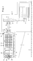
- FIGS. 1 to 3 are basically so-called horizontal agitator mills. These have in the usual way a stand 1 which is supported on the floor 2. At the front 3 of the stand 1, a support arm 4 is attached.
- the drive shaft 9 is rotatably supported in the stand 1 by means of a plurality of bearings 10.
- An essentially cylindrical grinding container 12 is supported on the support arm 4 in corresponding receptacles 11.
- the grinding container 12 has a cylindrical wall 13 and is closed at one end facing the stand 1 by means of a cover 14 and at the opposite end by means of a base 15. It encloses a grinding room 16.
- An agitator shaft 18, which passes through the cover 14, is arranged in the grinding chamber 16 concentrically to the common central longitudinal axis 17 of the grinding container 12 and the drive shaft 9.
- the grinding chamber 16 is sealed by means of seals 19 between the cover 14 and the shaft 18.
- the shaft 18 is overhung, that is, it is no longer supported in the region of the bottom 15. It is provided over its length in the grinding chamber 16 with stirring tools 20, which in the present case are stirring disks 21.
- stirring disks 21 can additionally be provided with stirring bars 22 which extend parallel to the axis 17 and are arranged in the form of a cage and by means of which the centrifugal forces are increased.
- the grinding container 12 is provided with an outlet which is designed differently in the different embodiments. Common to all outlets is that a grinding aid retaining device, as is generally customary in agitator mills, is not provided.
- auxiliary grinding device retention devices are either sieves in various configurations or so-called separating gap separating devices, as are described for example in DE-PS 14 82 391 (corresponding to GB-PS 1 056 257).
- an outlet pipe 25 is arranged in the bottom 15 coaxially with the axis 17 and is provided with an opening 26 on the end face.
- This outlet pipe 25 extends close to the agitator shaft 18, i.e. up to the vicinity of the end-side agitator disc 21.
- a frusto-conical short tube section 27, which is open towards the bottom 15, is attached, which leaves a passage channel 28 free to the bottom 15.
- the outlet pipe 25 and the pipe section 27 overlap one another in the direction of the axis 17.
- the agitator shaft 18 is provided with outlet openings 29 adjacent to its free end, namely between the two last agitator disks 21, which open out into an outlet channel 30 in the hollow agitator shaft 18.
- the drain channel 30 opens out in the region of the end of the agitator shaft 18 lying outside the grinding container 12.
- the stirring bars 22 mentioned can be in the region of the opening 29.
- the agitator shaft 18 is provided with outlet openings 31 in the region of its free end and also there between the two last adjacent stirring disks 21 which open into a drainage channel open towards the free end of the agitator shaft 18 32 flow into. This in turn opens into an outlet pipe 33 arranged in the bottom 15, the end face of which leaves only as small a gap as possible with respect to the free end of the agitator shaft 18.
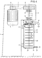
- the embodiment according to FIG. 4 is formed by a vertical agitator mill.
- the inlet connection 23 is provided in the area of the bottom 15 'below, which is provided with an emptying flap 24 '.
- the outlet is housed in the cover 14 ', where no seal is necessary or provided with respect to the agitator shaft 18.
- the outlet is formed by an outlet connector 34 surrounding the agitator shaft 18, between which and the shaft 18 an annular outlet channel 35 is delimited. This opens into an outlet cup 36 located above the lid 14 ', from which in turn a discharge line 37 opens.
- the agitator disk 21 adjacent to the cover 14 ' is only arranged with the release of a very narrow outlet gap 38 to the cover 14', so that high centrifugal forces are generated in the outlet gap 38.
- FIGS. 1 to 4 are agitator mills
- the embodiment according to FIG. 5 is constructed in the manner of a mixer which can be driven at high speed.
- parts that are functionally similar are provided with the same reference numbers, to which, however, a raised double line is added. To this extent, no further description is given.
- the agitator shaft 18 '' is mounted on the one hand in a bearing 10 '' in the area of the cover 14 '' and on the other hand in a bearing 10 '' in the area of the bottom 15 '', i.e. it is not flying, but is mounted on both ends.
- seals 19 ′′ are provided at the passage of the agitator shaft 18 ′′ through the cover 14 ′′ on the one hand and the bottom 15 ′′ on the other hand seals 19 ′′ are provided.
- the agitator shaft 18 ′′ is provided with agitating tools 20, which can again be agitating disks 21; the stirring tools 20 can, however, also be designed as classic shovel-like mixing tools 39, as is also shown in FIG. 5.
- An inlet connection 23 is provided adjacent to the cover 14 ′′, which opens into the grinding chamber 16 ′′.
- outlet openings 31 ′′ are formed in the agitator shaft 18 ′′, which lead into an outlet channel formed in the agitator mill 32 '', which in turn emerges behind the cover-side bearing 10 ''.
- the stirring bars 22 described can also be provided here.
- a storage container 40 is provided, which is connected to the inlet connection 23 via a feed line 41.
- a pump 43 driven by a motor 42 is connected, by means of which the material to be treated is transported.
- the drain channel 32 ′′ is in turn connected to the reservoir 40 via a return line 44.
- the grinding container 12 '' ' has a plurality of inlet connections 23' '' distributed over its length between the lid 14 '' 'and the bottom 15' '', which are supplied by means of a common feed line 41.
- An outlet pipe 25 '' ' opens out of the bottom 15' '' and runs concentrically to the central longitudinal axis 17.
- the drive shaft 9 is provided with a pot-shaped agitator, which is formed from a rotor disk 45 attached to the drive shaft 9, on which runs parallel and concentrically to the central longitudinal axis 17 and extends essentially over the length of the grinding container 12 '' ' Rods 46 are attached, which can be connected at their ends adjacent to the floor 15 '' 'for stiffening with a connecting ring 47.
- the rotor disk 45 with the bars 46 therefore forms a type of cage.
- Shovels or paddles 48 serving as stirring tools 20 are attached to the bars 46 and extend into the vicinity of the wall 13 '' 'of the grinding container 12' ''.
- the stirring tools 20 therefore only sweep over the radially outer region of the grinding chamber 16 '' '.
- the same reference numerals as in the previous figures have been used in FIG. 6 insofar as parts are identical. As far as parts are functionally identical, but structurally slightly different, they are identified by the same reference number but with a triple prime.
- the described embodiments of continuously operating devices are generally used in sewage treatment plants in order to subject the sludge accumulating there at different points to mechanical cell disruption. As can be seen from the above explanations results, all devices operate continuously. Any sludge that still contains organic components with mechanically unlockable cell walls is suitable for this mechanical treatment. In addition to the organic components, the sludge also contains a number of inorganic components. In the case of fresh sludge obtained, for example, by sedimentation or raw sludge already freed from coarse impurities by a rake, the organic fraction based on the dry matter is about 60% by weight and the inorganic fraction is therefore 40% by weight before such mechanical cell disruption. Furthermore, return sludge coming from flotation can also be subjected to the mechanical treatment.
- digested sludge discharged from a digestion tower in order to also carry out mechanical cell disruption in this.
- the organic fraction is usually approximately 50% by weight and consequently the inorganic fraction is also 50% by weight.
- Such digested sludge can be easily circulated by removing digested sludge from the digested container, subjecting it to mechanical cell disruption in a device and then feeding it back to the digested container.
- the inorganic constituents are finely dispersed sand and numerous insoluble metal compounds, usually in the form of salts, for example calcium phosphate, calcium carbonate, iron phosphate, etc.
- the treatment material described is placed in the grinding container 12 or 12 'or 12''or12''' supplied through the inlet connection 23 or the inlet connection 23 '''and intensively loaded by the stirring tools 20 rotating at high speed with the agitator shaft 18 or 18''.
- the grinding containers 12 or 12 'or 12''or12''' are completely filled with the material to be treated.
- This still untreated material to be treated has only a small proportion of inorganic constituents with a larger particle diameter, for example> 100 ⁇ m.
- inorganic particles of larger diameter contained in the material to be treated are, due to their greater density compared to the organic constituents, in the outer region, ie in the direction of the wall 13 or 13 '' or 13 '''of the grinding container 12, 12', 12 '' or 12 '''thrown. They form a ring of material close to the respective one Wall 13, 13 '' or 13 '''.
- outlets have a minimum width a, which is significantly larger than the inorganic particles of larger diameter or the existing foreign particles of larger diameter.
- the minimum width a of an outlet is at least 5 mm, usually at least 10 mm.
- the emptying flap 24 or 24 'or 24''or24''' can be used to remove inorganic contaminants if necessary.
- the proportion of the inorganic insoluble particles in the grinding chamber 16, 16 ′′, 16 ′′ ′′ should be very high in order to carry out the mechanical cell disruption as intensively as possible. So that such inorganic particles are strongly concentrated in the grinding chamber, the agitator speed on the one hand and the throughput of the material to be treated on the other hand must be optimally matched to one another.
- the power consumption of the drive motor 5 or 5 ′′ or its current consumption can serve as a key figure for this.
- the basic aim of regulation is to achieve a maximum of power consumption. This is again achieved through a high concentration of inorganic particles of large diameter.
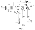
- a speed detection unit 49 is connected to the drive shaft 9 and thus to the agitator shaft 18, which outputs a signal corresponding to the speed to a regulating and control device 50.
- the power consumption of the drive motor 5 is also recorded by means of a power detection device 51 and passed on to the regulating and control device 50.
- a pump throughput detection device is also assigned to the pump 43, which outputs a signal corresponding to the throughput per unit time to the control control device 50.
- the throughput detection device 52 can be a speed measuring device, since the speed is a measure of the throughput in the case of pumps operating without slip or with constant slip.
- the drive motor 5 is assigned a speed adjustment device 53, which can be a frequency converter, for example.
- the drive motor 42 of the pump 43 is assigned a speed adjustment device 54, which can also be a frequency converter.
- the speed of the drive shaft 9, the power consumption of the drive motor 5 and the throughput of the pump 43 are entered as inputs 55, 56, 57 in the regulating and control device 50.
- a nominal value for the power consumption is input into the regulating and control device 50 via an input 58.
- the speed control device 53 of the drive motor 5 and the speed control device of the motor 41 of the pump 43 are controlled by the regulating and control device 50 according to the control scheme specified above via outputs 59, 60. In the first case, the speed of the agitator is changed; in the second case the throughput of the pump 43 is changed.
Landscapes
- Life Sciences & Earth Sciences (AREA)
- Hydrology & Water Resources (AREA)
- Engineering & Computer Science (AREA)
- Environmental & Geological Engineering (AREA)
- Water Supply & Treatment (AREA)
- Chemical & Material Sciences (AREA)
- Organic Chemistry (AREA)
- Treatment Of Sludge (AREA)
- Crushing And Grinding (AREA)
- Mixers Of The Rotary Stirring Type (AREA)
- Separation Of Solids By Using Liquids Or Pneumatic Power (AREA)
Abstract
Description
Die Erfindung betrifft ein Verfahren zum kontinuierlichen Aufschließen von organischen Bestandteilen eines fließfähigen, unlösliche anorganische Partikel enthaltenden Behandlungsguts, insbesondere von Schlamm, und eine Vorrichtung zur Durchführung des Verfahrens.The invention relates to a method for the continuous digestion of organic constituents of a treatment material containing flowable, insoluble inorganic particles, in particular sludge, and a device for carrying out the method.
Aus der DE 39 19 176 C2 ist es bekannt, organischen Schlamm, wie Klär-Schlamm und Schlamm aus landwirtschaftlichen und Fisch-Abfallprodukten anaerob abzubauen. Um den anaeroben Abbau zu verbessern bzw. zum Teil erst zu ermöglichen, werden die organischen Bestandteile des Schlammes mechanisch aufgeschlossen, indem deren Zellwände mechanisch zerstört werden. Hierzu wird eine Naßmahlbehandlung in einer Walzenmühle, einer vibrierenden Kugelmühle, einer Zentrifugenkugelmühle, einer mittelgroßen Rührmühle und einer Kolloidmühle vorgeschlagen. Konkret wird hierbei beschrieben, eine Vorrichtung einzusetzen, bei der eine sich drehende Scheibe, die in ein zylindrisches Gefäß eingebaut ist, mit hoher Drehzahl angetrieben wird, wodurch in dem Gehäuse enthaltene kleine Kugeln, bei denen es sich um Mahlhilfskörper handelt, kräftig gerührt werden. Diese kleinen Kugeln üben eine Scherkraft auf das Behandlungsgut aus und zertrümmern es. Für das Löslichmachen von Schlamm werden Mahlhilfskörper mit einem Durchmesser von 0,05 bis 1 mm eingesetzt. Bei Verwendung von Mahlhilfskörpern dieser Größe ist eine Umdrehungsgeschwindigkeit für die Drehscheibe zwischen 1000 bis 3000 min⁻¹ entsprechend einer Umlaufgeschwindigkeit von 10 bis 30 m/sec vorgesehen. Bei Behandlung von normalem Schlamm soll eine Behandlungsdauer von 5 bis 60 Minuten angemessen sein.It is known from DE 39 19 176 C2 to anaerobically break down organic sludge, such as sewage sludge and sludge, from agricultural and fish waste products. In order to improve the anaerobic degradation or to enable it in part, the organic components of the sludge are mechanically broken down by mechanically destroying their cell walls. For this purpose, a wet grinding treatment in a roller mill, a vibrating ball mill, a centrifuge ball mill, a medium-sized agitator mill and a colloid mill is proposed. Specifically, it is described here to use a device in which a rotating disc, which is built into a cylindrical vessel, is driven at high speed, as a result of which small balls contained in the housing, which are grinding aid bodies, are stirred vigorously. These small balls exert a shear force on the material to be treated and break it up. Auxiliary grinding media with a diameter of 0.05 to 1 mm are used to make sludge soluble. When using grinding aids of this size, a speed of rotation for the turntable between 1000 to 3000 min⁻¹ corresponding to a speed of 10 to 30 m / sec is provided. When treating normal sludge, a treatment time of 5 to 60 minutes should be appropriate.
Derartiges fließfähiges Behandlungsgut, und zwar insbesondere Schlamm, kann sehr niedrigviskos sein, so daß der Mahlhilfskörperverschleiß in der Rührmühle bzw. Rührwerksmühle außerordentlich hoch ist. Des weiteren weist derartiges Behandlungsgut sehr oft verhältnismäßig große Fremdpartikel auf, die die Trenneinrichtung zusetzen können, wodurch dann wiederum die Abtrennung der Mahlhilfskörper vom behandelten Gut bei einem kontinuierlichen Betrieb stark beeinträchtigt wird. Deshalb ist die Abtrennung der Mahlhilfskörper vom behandelten Gut bei einem kontinuierlichen Betrieb außerordentlich schwierig.Such flowable material to be treated, in particular sludge, can be very low-viscosity, so that the grinding auxiliary body wear in the agitator mill or agitator mill is extremely high. Furthermore, such material to be treated very often has relatively large foreign particles which can clog the separating device, which in turn then severely impairs the separation of the auxiliary grinding bodies from the material to be treated during continuous operation. For this reason, it is extremely difficult to separate the grinding aids from the treated material in continuous operation.
Aus der DE 40 30 668 A1 ist es ebenfalls bekannt, biologisch gebildete Schlämme durch Desintegration aufzubrechen. Hierbei werden die Zellwände der den organischen Anteil des Schlammes ausmachenden Mikroorganismen zerstört.From DE 40 30 668 A1 it is also known to disintegrate biologically formed sludges by disintegration. This destroys the cell walls of the microorganisms that make up the organic part of the sludge.
Der Erfindung liegt die Aufgabe zugrunde, ein Verfahren und eine Vorrichtung der eingangs angegebenen Art zu schaffen, das einen kontinuierlichen Aufschluß der organischen Bestandteile des Behandlungsguts in besonders einfacher Weise ermöglicht.The invention has for its object to provide a method and an apparatus of the type specified that enables continuous digestion of the organic components of the material to be treated in a particularly simple manner.
Diese Aufgabe wird bei einem Verfahren der eingangs angegebenen Art durch die Merkmale des Anspruches 1 gelöst. Sie wird weiterhin bei einer Vorrichtung der eingangs genannten Art durch die Merkmale des Anspruches 6 gelöst. Der Kern der Erfindung besteht darin, daß die ohnehin im Behandlungsgut enthaltenen unlöslichen anorganischen Partikel mit einer größeren Dichte als die aufzuschließenden organischen Bestandteile durch die auf sie ausgeübten Zentrifugalwirkungen im Behandlungsraum aufkonzentriert und dort gleichsam als Mahlhilfskörper verwendet werden. Es werden also keine eigenständigen Mahlhilfskörper verwendet; weiterhin ist keine Mahlhilfskörper-Rückhaltevorrichtung notwendig, da die unlöslichen anorganischen Bestandteile, die die Funktion von Mahlhilfskörpern ausüben, Bestandteile des Behandlungsguts sind. Bei dem Behandlungsraum kann es sich - bevorzugt - um den Mahlraum einer nach Art einer Rührwerksmühle aufgebauten Vorrichtung handeln; es kann aber auch eine Zentrifuge oder dergleichen nach entsprechender Anpassung eingesetzt werden.This object is achieved in a method of the type specified at the outset by the features of
Zahlreiche zum Teil erfinderische Ausgestaltungen ergeben sich aus den Unteransprüchen.Numerous configurations, some of which are inventive, result from the subclaims.
Weitere Merkmale, Vorteile und Einzelheiten der Erfindung ergeben sich aus der nachfolgenden Beschreibung von fünf Ausführungsbeispielen anhand der Zeichnung. Es zeigt
- Fig. 1
- eine erste nach Art einer Rührwerksmühle aufgebaute Ausführungsform einer Vorrichtung zum Aufschluß von Schlamm im Vertikalschnitt in schematischer Darstellung,
- Fig. 2
- eine zweite nach Art einer Rührwerksmühle aufgebaute Ausführungsform einer Vorrichtung zum Aufschluß von Schlamm im Vertikalschnitt in schematischer Darstellung,
- Fig. 3
- eine dritte nach Art einer Rührwerksmühle aufgebaute Ausführungsform einer Vorrichtung zum Aufschluß von Schlamm im Vertikalschnitt in schematischer Darstellung,
- Fig. 4
- eine vierte nach Art einer Rührwerksmühle aufgebaute Ausführungsform einer Vorrichtung zum Aufschluß von Schlamm im Vertikalschnitt in schematischer Darstellung,
- Fig. 5
- eine fünfte nach Art eines Ringmischers aufgebaute Ausführungsform einer Vorrichtung zum Aufschluß von Schlamm im Vertikalschnitt in schematischer Darstellung,
- Fig. 6
- eine sechste nach Art einer Rührwerksmühle aufgebaute Ausführungsform einer Vorrichtung zum Aufschluß von Schlamm im Vertikalschnitt in schematischer Darstellung und
- Fig. 7
- ein Regelungs-Blockschaltbild für eine Rührwerksmühle.
- Fig. 1
- 1 shows a first embodiment of a device for disintegrating sludge, constructed in the manner of an agitator mill, in a vertical section in a schematic illustration,
- Fig. 2
- A second embodiment of a device for disintegrating sludge constructed in the manner of a stirrer mill in vertical section in a schematic representation,
- Fig. 3
- A third embodiment of a device for disintegrating sludge constructed in the manner of an agitator mill in vertical section in a schematic representation,
- Fig. 4
- 4 shows a fourth embodiment of a device for digesting sludge, constructed in the manner of an agitator mill, in vertical section in a schematic illustration,
- Fig. 5
- A fifth embodiment of a device for disintegrating sludge constructed in the manner of a ring mixer in vertical section in a schematic representation,
- Fig. 6
- a sixth constructed in the manner of an agitator mill embodiment of a device for digesting sludge in vertical section in a schematic representation and
- Fig. 7
- a control block diagram for an agitator mill.
Bei den Ausführungsformen nach den Fig. 1 bis 3 handelt es sich im Grundsatz um sogenannte liegende Rührwerksmühlen. Diese weisen in üblicher Weise einen Ständer 1 auf, der auf dem Boden 2 abgestützt ist. An der Vorderseite 3 des Ständers 1 ist ein Tragarm 4 angebracht.The embodiments according to FIGS. 1 to 3 are basically so-called horizontal agitator mills. These have in the usual way a
Im Ständer ist ein gegebenenfalls drehzahlregelbarer Antriebsmotor 5 untergebracht, der mit einer Keilriemenscheibe 6 versehen ist, von der über Keilriemen 7 und eine weitere Keilriemenscheibe 8 eine Antriebswelle 9 drehantreibbar ist. Die Antriebswelle 9 ist im Ständer 1 mittels mehrerer Lager 10 drehbar gelagert.A
Auf dem Tragarm 4 ist in entsprechenden Aufnahmen 11 ein im wesentlichen zylindrischer Mahlbehälter 12 abgestützt. Der Mahlbehälter 12 weist eine zylindrische Wand 13 auf und ist an einem, dem Ständer 1 zugewandten Ende mittels eines Deckels 14 und am gegenüberliegenden Ende mittels eines Bodens 15 verschlossen. Er umschließt einen Mahlraum 16.An essentially
Konzentrisch zur gemeinsamen Mittel-Längs-Achse 17 von Mahlbehälter 12 und Antriebswelle 9 ist im Mahlraum 16 eine Rührwerks-Welle 18 angeordnet, die den Deckel 14 durchsetzt. Der Mahlraum 16 ist mittels Dichtungen 19 zwischen dem Deckel 14 und der Welle 18 abgedichtet. Die Welle 18 ist fliegend gelagert, also im Bereich des Bodens 15 nicht mehr gelagert. Sie ist über ihre Länge im Mahlraum 16 mit Rührwerkzeugen 20 versehen, bei denen es sich im vorliegenden Fall um Rührscheiben 21 handelt. Diese Rührscheiben 21 können - wie in Fig. 1 rechts dargestellt - zusätzlich mit sich parallel zur Achse 17 erstreckenden, in Form eines Käfigs angeordneten Rührstäben 22 versehen sein, mittels derer die Zentrifugalkräfte erhöht werden.An
Am Mahlbehälter 12 ist - benachbart zum Deckel 14 - ein Zulaufstutzen 23 angebracht, durch den zu behandelndes Gut, in der Regel also Schlamm, zugeführt wird. An der unten liegenden Seite der Wand 13 des Mahlbehälters 12 ist eine sich über einen wesentlichen Teil der Länge des Mahlbehälters 12 zwischen den Aufnahmen 11 erstreckende Entleerungsklappe 24 angebracht.On the grinding container 12 - adjacent to the lid 14 - there is an
Bei allen Ausführungsformen ist der Mahlbehälter 12 mit einem Auslaß versehen, der bei den verschiedenen Ausführungsformen unterschiedlich ausgestaltet ist. Gemeinsam ist allen Auslässen, daß eine Mahlhilfskörper-Rückhaltevorrichtung, wie sie bei Rührwerksmühlen generell üblich ist, nicht vorgesehen ist. Bei derartigen Mahlhilfskörper-Rückhaltevorrichtungen handelt es sich entweder um Siebe in vielerlei Ausgestaltungen oder um sogenannte Trennspalt-Abtrennvorrichtungen, wie sie beispielsweise in der DE-PS 14 82 391 (entspr. GB-PS 1 056 257) beschrieben sind.In all embodiments, the grinding
Bei der Ausführungsform nach Fig. 1 ist im Boden 15 koaxial zur Achse 17 ein Auslaß-Rohr 25 angeordnet, das stirnseitig mit einer Öffnung 26 versehen ist. Dieses Auslaß-Rohr 25 reicht bis in die Nähe der Rührwerks-Welle 18, d.h. bis in die Nähe der endseitigen Rührscheibe 21. An dieser endseitigen Rührscheibe 21 ist ein beispielsweise kegelstumpfförmiger, zum Boden 15 hin offener kurzer Rohr-Abschnitt 27 angebracht, der zum Boden 15 einen Durchtrittskanal 28 frei läßt. Das Auslaß-Rohr 25 und der Rohr-Abschnitt 27 überdecken einander in Richtung der Achse 17.In the embodiment according to FIG. 1, an
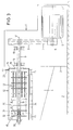
Bei der Ausführungsform nach Fig. 2 ist die Rührwerks-Welle 18 benachbart zu ihrem freien Ende, und zwar zwischen den beiden letzten Rührscheiben 21, mit Auslaß-Öffnungen 29 versehen, die in einen Ablaufkanal 30 in der hohlen Rührwerks-Welle 18 einmünden. Der Ablaufkanal 30 mündet im Bereich des außerhalb des Mahlbehälters 12 liegenden Endes der Rührwerks-Welle 18 aus dieser aus. Zur Verstärkung des Zentrifugaleffektes können im Bereich der Öffnung 29 die erwähnten Rührstäbe 22 sein.In the embodiment according to FIG. 2, the
Bei der Ausführungsform nach Fig. 3 ist die Rührwerks-Welle 18 im Bereich ihres freien Endes und auch dort zwischen den beiden letzten einander benachbarten Rührscheiben 21 mit Auslaß-Öffnungen 31 versehen, die in einen zum freien Ende der Rührwerks-Welle 18 hin offenen Ablaufkanal 32 einmünden. Dieser mündet wiederum in ein im Boden 15 angeordnetes Auslaß-Rohr 33, das mit seiner Stirnseite gegenüber dem freien Ende der Rührwerks-Welle 18 nur einen möglichst kleinen Spalt frei läßt.In the embodiment according to FIG. 3, the
Die Ausführungsform nach Fig. 4 wird durch eine vertikale Rührwerksmühle gebildet. Soweit die Teile identisch sind, werden gleiche Bezugsziffern wie bei den Fig. 1 bis 3 verwendet, soweit einzelne Teile nur konstruktiv unterschiedlich, funktionell aber gleich sind, werden die gleichen Bezugsziffern wie bei den Ausführungsformen nach den Fig. 1 bis 3 verwendet, jedoch mit einem hochgesetzten Strich versehen. Der Zulaufstutzen 23 ist hierbei im Bereich des unten liegenden Bodens 15' vorgesehen, der mit einer Entleerungsklappe 24' versehen ist. Der Auslaß ist im Deckel 14' untergebracht, wo gegenüber der Rührwerks-Welle 18 keine Dichtung notwendig bzw. vorgesehen ist. Der Auslaß wird durch einen die Rührwerks-Welle 18 umgebenden Auslaß-Stutzen 34 gebildet, zwischen dem und der Welle 18 ein ringförmiger Auslaß-Kanal 35 begrenzt wird. Dieser mündet in eine oberhalb des Deckels 14' befindliche Auslaß-Tasse 36, aus der wiederum eine Abführ-Leitung 37 ausmündet.The embodiment according to FIG. 4 is formed by a vertical agitator mill. Insofar as the parts are identical, the same reference numerals are used as in FIGS. 1 to 3, and insofar as individual parts are only structurally different but functionally the same, the same reference numerals are used as in the embodiments according to FIGS. 1 to 3, but with put a dash. The
Die dem Deckel 14' benachbarte Rührscheibe 21 ist nur unter Freilassung eines sehr schmalen Auslaßspaltes 38 zum Deckel 14' angeordnet, so daß gerade im Auslaßspalt 38 hohe Zentrifugalkräfte erzeugt werden.The
Während die Ausführungsformen nach den Fig. 1 bis 4 Rührwerksmühlen sind, ist die Ausführungsform nach Fig. 5 nach Art eines hochtourig antreibbaren Mischers aufgebaut. Mit den Ausführungsformen nach den Fig. 1 bis 3 funktionell gleichartige Teile werden mit den gleichen Bezugsziffern versehen, denen jedoch ein hochgesetzter Doppelstrich beigefügt wird. Von einer erneuten Beschreibung wird insoweit Abstand genommen.While the embodiments according to FIGS. 1 to 4 are agitator mills, the embodiment according to FIG. 5 is constructed in the manner of a mixer which can be driven at high speed. With the embodiments according to FIGS. 1 to 3, parts that are functionally similar are provided with the same reference numbers, to which, however, a raised double line is added. To this extent, no further description is given.
Die Rührwerks-Welle 18'' ist einerseits in einem Lager 10'' im Bereich des Deckels 14'' und andererseits in einem Lager 10'' im Bereich des Bodens 15'' gelagert, d.h. sie ist nicht fliegend, sondern beidendig gelagert. Am Durchtritt der Rührwerks-Welle 18'' durch den Deckel 14'' einerseits und den Boden 15'' andererseits sind Dichtungen 19'' vorgesehen. Die Rührwerks-Welle 18'' ist mit Rührwerkzeugen 20 versehen, bei denen es sich ebenfalls wieder um Rührscheiben 21 handeln kann; die Rührwerkzeuge 20 können aber auch als klassische schaufelartige Mischwerkzeuge 39 ausgebildet sein, wie es ebenfalls in Fig. 5 dargestellt ist.The agitator shaft 18 '' is mounted on the one hand in a bearing 10 '' in the area of the cover 14 '' and on the other hand in a bearing 10 '' in the area of the bottom 15 '', i.e. it is not flying, but is mounted on both ends. At the passage of the
Benachbart zum Deckel 14'' ist ein Zulaufstutzen 23 vorgesehen, der in den Mahlraum 16'' einmündet.An
Benachbart zum Boden 15'', und zwar auch dort zwischen den beiden letzten Rührscheiben 21, sind in der Rührwerks-Welle 18'' Auslaß-Öffnungen 31'' ausgebildet, die in einen in der Rührwerksmühle ausgebildeten Ablaufkanal 32'' münden, der wiederum hinter dem deckelseitigen Lager 10'' austritt. Auch hier können selbstverständlich die geschilderten Rührstäbe 22 vorgesehen werden.Adjacent to the
Nur in Fig. 5 ist angedeutet, daß das Behandlungsgut dem Behandlungsprozeß mehrfach zugeführt wird. Hierzu ist ein Vorratsbehälter 40 vorgesehen, der über eine Zuführleitung 41 mit dem Zulaufstutzen 23 verbunden ist. In diese Zuführleitung 41 ist eine von einem Motor 42 angetriebene Pumpe 43 geschaltet, mittels derer der Transport des Behandlungsguts erfolgt. Der Ablaufkanal 32'' ist wiederum über eine Rückführleitung 44 mit dem Vorratsbehälter 40 verbunden.Only in Fig. 5 is indicated that the material to be treated is fed to the treatment process several times. For this purpose, a
Bei der Ausführungsform nach Fig. 6 weist der Mahlbehälter 12''' über seine Länge zwischen dem Deckel 14''' und dem Boden 15''' verteilt mehrere Zulaufstutzen 23''' auf, die mittels einer gemeinsamen Zuführleitung 41 versorgt werden. Aus dem Boden 15''' mündet ein Auslaß-Rohr 25''' aus, das konzentrisch zur Mittel-Längs-Achse 17 verläuft. Die Antriebswelle 9 ist mit einem topfförmigem Rührwerk versehen, das aus einer an der Antriebswelle 9 angebrachten Rotorscheibe 45 gebildet ist, an dem parallel und konzentrisch zur Mittel-Längs-Achse 17 verlaufende, sich im wesentlichen über die Länge des Mahlbehälters 12''' erstreckende Stäbe 46 angebracht sind, die an ihren benachbart zum Boden 15''' befindlichen Enden zur Aussteifung mit einem Verbindungsring 47 verbunden sein können. Die Rotorscheibe 45 mit den Stäben 46 bildet daher eine Art Käfig. An den Stäben 46 sind als Rührwerkzeuge 20 dienende Schaufeln bzw. Paddel 48 angebracht, die sich bis in die Nähe der Wand 13''' des Mahlbehälters 12''' erstrecken. Die Rührwerkzeuge 20 überstreichen also nur den radial außenliegenden Bereich des Mahlraumes 16'''. Im übrigen sind in Fig. 6 dieselben Bezugsziffern wie in den vorherigen Figuren verwendet worden, soweit Teile identisch sind. Soweit Teile funktionell identisch, aber konstruktiv geringfügig anders sind, sind sie mit derselben Bezugsziffer aber mit einem hochgesetzten Dreifachstrich bezeichnet.In the embodiment according to FIG. 6, the grinding container 12 '' 'has a plurality of inlet connections 23' '' distributed over its length between the lid 14 '' 'and the bottom 15' '', which are supplied by means of a
Die geschilderten Ausführungsformen von kontinuierlich arbeitenden Vorrichtungen werden in der Regel in Kläranlagen eingesetzt, um den dort an unterschiedlichen Stellen anfallenden Schlamm einem mechanischen Zellaufschluß zu unterwerfen. Wie sich aus den vorstehenden Erläuterungen ergibt, arbeiten alle Vorrichtungen kontinuierlich. Jeder Schlamm, der noch organische Bestandteile mit mechanisch aufschließbaren Zellwänden aufweist, ist für diese mechanische Behandlung geeignet. Außer den organischen Anteilen enthält der Schlamm auch eine Reihe von anorganischen Bestandteilen. Bei beispielsweise durch Sedimentation gewonnenem Frischschlamm oder bereits durch einen Rechen von groben Verunreinigungen befreitem Rohschlamm beträgt vor einem solchen mechanischen Zellaufschluß der organische Anteil bezogen auf die Trockensubstanz ca. 60 Gew.% und der anorganische Anteil somit 40 Gew.%. Weiterhin kann auch aus einer Flotation kommender Rücklaufschlamm der mechanischen Behandlung unterworfen werden. Weiterhin ist es möglich, den verschiedenen Ausführungsformen von Vorrichtungen aus einem Faulturm ausgetragenen Faulschlamm zuzuführen, um auch bei diesem einen mechanischen Zellaufschluß durchzuführen. Bei aus einem Faulbehälter ausgetragenem Faulschlamm liegt - ebenfalls bezogen auf die Trockensubstanz - der organische Anteil üblicherweise bei ca. 50 Gew.% und demzufolge der anorganische Anteil ebenfalls bei 50 Gew.%. Gerade derartiger Faulschlamm kann ohne weiteres im Kreislauf geführt werden, indem dem Faulbehälter Faulschlamm entnommen, dieser in einer Vorrichtung einem mechanischen Zellaufschluß unterworfen und dann wieder dem Faulbehälter zugeführt wird.The described embodiments of continuously operating devices are generally used in sewage treatment plants in order to subject the sludge accumulating there at different points to mechanical cell disruption. As can be seen from the above explanations results, all devices operate continuously. Any sludge that still contains organic components with mechanically unlockable cell walls is suitable for this mechanical treatment. In addition to the organic components, the sludge also contains a number of inorganic components. In the case of fresh sludge obtained, for example, by sedimentation or raw sludge already freed from coarse impurities by a rake, the organic fraction based on the dry matter is about 60% by weight and the inorganic fraction is therefore 40% by weight before such mechanical cell disruption. Furthermore, return sludge coming from flotation can also be subjected to the mechanical treatment. Furthermore, it is possible to supply the various embodiments of devices with digested sludge discharged from a digestion tower in order to also carry out mechanical cell disruption in this. In the case of digested sludge discharged from a digester, also based on the dry matter, the organic fraction is usually approximately 50% by weight and consequently the inorganic fraction is also 50% by weight. Such digested sludge can be easily circulated by removing digested sludge from the digested container, subjecting it to mechanical cell disruption in a device and then feeding it back to the digested container.
Bei den anorganischen Bestandteilen handelt es sich um feindispersen Sand und zahlreiche unlösliche Metallverbindungen, üblicherweise in Form von Salzen, beispielsweise Calciumphosphat, Calciumcarbonat, Eisenphosphat, usw. Das geschilderte Behandlungsgut wird dem Mahlbehälter 12 bzw. 12' bzw. 12'' bzw. 12''' durch den Zulaufstutzen 23 bzw. die Zulaufstutzen 23''' zugeführt und durch die hochtourig mit der Rührwerks-Welle 18 bzw. 18'' umlaufenden Rührwerkzeuge 20 intensiv beaufschlagt. Die Mahlbehälter 12 bzw. 12' bzw. 12'' bzw. 12''' sind mit dem Behandlungsgut vollständig gefüllt. Dieses noch unbehandelte Behandlungsgut weist nur einen kleinen Anteil anorganischer Bestandteile mit einem größeren Partikeldurchmesser, beispielsweise > 100 µm, auf. Diese im Behandlungsgut enthaltenen anorganischen Partikel größeren Durchmessers werden aufgrund ihrer größeren Dichte im Vergleich zu den organischen Bestandteilen in den Außenbereich, d.h. in Richtung zur Wand 13 bzw. 13'' bzw. 13''' des Mahlbehälters 12, 12', 12'' bzw. 12''' geschleudert. Sie bilden einen Materialring in der Nähe der jeweiligen Wand 13, 13'' bzw. 13'''. Da das Behandlungsgut im Bereich der Achse 17 bzw. der Welle 18 bzw. 18'' durch die geschilderten Auslässe 25, 29, 31, 31'', 34, 25''' aus dem Mahlraum 16, 16'', 16''' austritt, verbleiben diese größeren anorganischen Partikel - und naturgemäß auch kleinere anorganische Partikel - im Mahlraum 16, 16'', 16'''; sie werden im Mahlraum 16, 16'', 16''' aufkonzentriert. Diese von den Rührwerkzeugen 20 aktivierten Partikel bewirken als Mahlhilfskörper den Aufschluß des Behandlungsgutes durch Zerstörung der Zellwände der organischen Bestandteile des Behandlungsgutes. Soweit derartige anorganische Partikel größeren Durchmessers mit dem behandelten Mahlgut ausgetragen werden, können sie nicht eine Rückhaltevorrichtung zusetzen, da eine solche nicht vorhanden ist. Entsprechendes gilt im Hinblick auf im Behandlungsgut vorhandene Fremdpartikel größeren Durchmessers. Alle Auslässe weisen eine minimale Weite a, die deutlich größer als die anorganischen Partikel größeren Durchmessers bzw. die vorhandenen Fremdpartikel größeren Durchmessers ist. Die minimale Weite a eines Auslasses beträgt mindestens 5 mm in der Regel mindestens 10 mm.The inorganic constituents are finely dispersed sand and numerous insoluble metal compounds, usually in the form of salts, for example calcium phosphate, calcium carbonate, iron phosphate, etc. The treatment material described is placed in the grinding
Die Entleerungsklappe 24 bzw. 24' bzw. 24'' bzw. 24''' kann dazu verwendet werden, anorganische Verunreinigungen bei Bedarf zu entfernen. Der Anteil der anorganischen unlöslichen Partikel im Mahlraum 16, 16'', 16''' sollte sehr hoch sein, um den mechanischen Zellaufschluß möglichst intensiv durchzuführen. Damit eine starke Aufkonzentration solcher anorganischen Partikel im Mahlraum erfolgt, müssen die Rührwerksdrehzahl einerseits und der Durchsatz des Behandlungsgutes andererseits einander optimal angepaßt werden. Als Kennzahl hierfür kann die Leistungsaufnahme des Antriebsmotors 5 bzw. 5'' oder aber dessen Stromaufnahme dienen. Grundsätzliches Ziel einer Regelung ist es, ein Maximum der Leistungsaufnahme zu erreichen. Dies wird wiederum erreicht durch eine hohe Konzentration von anorganischen Partikeln großen Durchmessers. Wenn bei einer Steigerung des Durchsatzes die Leistungsaufnahme abnimmt, so ist daraus zu schließen, daß die anorganischen Partikel größeren Durchmessers aus dem Mahlraum 16, 16'' mit dem behandelten Mahlgut ausgetragen werden, so daß der Mahleffekt verringert wird. In diesem Fall muß entweder der Durchsatz an Behandlungsgut reduziert werden, oder aber bei Vorhandensein eines drehzahlregelbaren Antriebsmotors 5 die Drehzahl der Rührwerkswelle 18, 18'' erhöht werden.The emptying
Konkret kann die Regelung in der in Fig. 7 dargestellten Weise durchgeführt werden. Mit der Antriebswelle 9 und damit mit der Rührwerks-Welle 18 ist eine Drehzahl-Erfassungseinheit 49 verbunden, die ein der Drehzahl entsprechendes Signal auf eine Regel- und Steuereinrichtung 50 gibt. Es wird weiterhin die Leistungsaufnahme des Antriebsmotors 5 mittels eines Leistungs-Erfassungsgerätes 51 aufgenommen und an die Regel- und Steuereinrichtung 50 gegeben. Es ist weiterhin der Pumpe 43 ein Durchsatz-Erfassungseinrichtung zugeordnet, die ein dem Durchsatz pro Zeiteinheit entsprechendes Signal an die Regel-Steuereinrichtung 50 abgibt. Bei der Durchsatz-Erfassungseinrichtung 52 kann es sich um ein Drehzahlmeßgerät handeln, da bei schlupffrei oder mit konstantem Schlupf arbeitenden Pumpen die Drehzahl ein Maß für den Durchsatz ist. Weiterhin ist dem Antriebsmotor 5 eine Drehzahlverstellvorrichtung 53 zugeordnet, bei der es sich beispielsweise um einen Frequenzumrichter handeln kann. In gleicher Weise ist dem Antriebsmotor 42 der Pumpe 43 eine Drehzahlverstellvorrichtung 54 zugeordnet, bei der es sich ebenfalls um einen Frequenzumrichter handeln kann. Die Drehzahl der Antriebswelle 9, die Leistungsaufnahme des Antriebsmotors 5 und der Durchsatz der Pumpe 43 werden als Eingänge 55, 56, 57 in die Regel- und Steuereinrichtung 50 eingegeben. Weiterhin wird ein Sollwert für die Leistungsaufnahme über einen Eingang 58 in die Regel- und Steuereinrichtung 50 eingegeben. Von der Regel- und Steuereinrichtung 50 wird nach dem vorstehend angegebenen Regelungsschema über Ausgänge 59, 60 die Drehzahlverstellvorrichtung 53 des Antriebsmotors 5 und die Drehzahlverstellvorrichtung des Motors 41 der Pumpe 43 angesteuert. Im ersten Fall wird die Drehzahl des Rührwerks geändert; im zweiten Fall wird der Durchsatz der Pumpe 43 geändert.Specifically, the regulation can be carried out in the manner shown in FIG. 7. A speed detection unit 49 is connected to the
Claims (24)
wobei das Behandlungsgut in einem Behandlungsraum (16, 16'', 16''') konzentrisch zu einer Achse (Mittel-Längs-Achse 17) in Rotation versetzt wird und
wobei die unlöslichen anorganischen Partikel im Behandlungsraum (16, 16'', 16''') aufkonzentriert werden.Process for the continuous digestion of organic constituents of a treatment material containing flowable insoluble inorganic particles, in particular sludge,
wherein the material to be treated is rotated in a treatment room (16, 16 ″, 16 ″ ″) concentrically to an axis (central longitudinal axis 17) and
the insoluble inorganic particles being concentrated in the treatment room (16, 16 '', 16 ''').
mit einem einen mahlhilfskörperfreien Mahlraum (16, 16'', 16''') umschließenden Mahlbehälter (12, 12', 12'', 12'''),
mit einem konzentrisch zur Achse (Mittel-Längs-Achse 17) des Mahlbehälters (12, 12', 12'', 12''') in diesem drehbar angeordneten Rührwerk,
mit an dem Rührwerk angebrachten Rührwerkzeugen (20),
mit einem mit dem Rührwerk gekoppelten Antriebsmotor (5, 5''),
mit mindestens einem in den Mahlraum (16, 16'', 16''') mündenden Zulaufstutzen (23, 23''') für Behandlungsgut und
mit mindestens einem im Bereich der Achse (Mittel-Längs-Achse 17) angeordneten, keine Mahlhilfskörper-Rückhaltevorrichtung aufweisenden Auslaß (Auslaß-Rohr 25, 25''',
Auslaß-Öffnung 29, Auslaß-Öffnung 31, 31'', Auslaß-Stutzen 34) für behandeltes Behandlungsgut.Device for carrying out the method according to one of claims 1 to 5,
with a grinding container (12, 12 ', 12'',12''') enclosing a grinding chamber (16, 16 '', 16 ''') which is free of grinding aids,
with a concentric to the axis (central longitudinal axis 17) of the grinding container (12, 12 ', 12'',12''') in this rotatably arranged agitator,
with stirring tools (20) attached to the agitator,
with a drive motor (5, 5 '') coupled to the agitator,
with at least one inlet connection (23, 23 ''') opening into the grinding chamber (16, 16'',16''') for the material to be treated and
with at least one outlet (outlet pipe 25, 25 ''') arranged in the region of the axle (central longitudinal axle 17) and not having any auxiliary grinding device retention device,
Outlet opening 29, outlet opening 31, 31 '', outlet nozzle 34) for treated material to be treated.
Applications Claiming Priority (2)
| Application Number | Priority Date | Filing Date | Title |
|---|---|---|---|
| DE4432154 | 1994-09-09 | ||
| DE4432154A DE4432154A1 (en) | 1994-09-09 | 1994-09-09 | Method and device for the continuous digestion of organic components of a flowable material to be treated |
Publications (3)
| Publication Number | Publication Date |
|---|---|
| EP0700875A2 true EP0700875A2 (en) | 1996-03-13 |
| EP0700875A3 EP0700875A3 (en) | 1998-01-28 |
| EP0700875B1 EP0700875B1 (en) | 2000-03-01 |
Family
ID=6527818
Family Applications (1)
| Application Number | Title | Priority Date | Filing Date |
|---|---|---|---|
| EP95112854A Expired - Lifetime EP0700875B1 (en) | 1994-09-09 | 1995-08-16 | Method and apparatus for continuous solubilizing of organic compounds of a flowable material containing insoluble inorganic compounds |
Country Status (4)
| Country | Link |
|---|---|
| EP (1) | EP0700875B1 (en) |
| JP (1) | JPH0889835A (en) |
| AT (1) | ATE190047T1 (en) |
| DE (2) | DE4432154A1 (en) |
Cited By (1)
| Publication number | Priority date | Publication date | Assignee | Title |
|---|---|---|---|---|
| CN109647609A (en) * | 2019-01-14 | 2019-04-19 | 乌拉特中旗毅腾矿业有限责任公司 | A kind of raw coal initial stage cleaning treatment technique |
Families Citing this family (2)
| Publication number | Priority date | Publication date | Assignee | Title |
|---|---|---|---|---|
| DE102010049827A1 (en) * | 2010-10-27 | 2012-05-03 | Netzsch-Feinmahltechnik Gmbh | stirred ball mill |
| DE202020104352U1 (en) * | 2020-07-28 | 2020-08-06 | ADS Advanced Diagnosis Systems AG | Device for the mechanical disintegration of sewage sludge |
Citations (3)
| Publication number | Priority date | Publication date | Assignee | Title |
|---|---|---|---|---|
| DE1482391B1 (en) | 1964-06-20 | 1970-08-20 | Draiswerke Gmbh | Agitator mill |
| DE4030668A1 (en) | 1990-09-28 | 1992-04-02 | Peter Prof Dr Kunz | Appts. for redn. of vol. of biological sludge - has cell structure of sludge is broken down by mechanicaldisintegrator and resulting material is subjected to further biological treatment |
| DE3919176C2 (en) | 1988-09-16 | 1992-12-10 | Fujita Corp., Tokio/Tokyo, Jp |
Family Cites Families (11)
| Publication number | Priority date | Publication date | Assignee | Title |
|---|---|---|---|---|
| DE2254844A1 (en) * | 1972-11-09 | 1974-05-22 | Loesche Kg | METHOD AND EQUIPMENT FOR THE PROCESSING OF MUELL |
| GB1464517A (en) * | 1974-11-25 | 1977-02-16 | Electrolux Ab | Method of processing waste in a ship and apparatus and arrangement for carrying out the method |
| DE2827865A1 (en) * | 1978-06-24 | 1980-01-17 | Draiswerke Gmbh | Grinding mill for resinous dispersions - in which cooled shaft rotates spurs meshing with spurs from barrel |
| AT367657B (en) * | 1978-08-24 | 1982-07-26 | Buehler Ag Geb | AGITATOR BALL MILL CONTROL |
| DE2845763A1 (en) * | 1978-10-20 | 1980-04-30 | Goepfert Peter | Domestic refuse preparation system - homogenises by intensive mixing before burning |
| DE3106062A1 (en) * | 1981-02-19 | 1982-09-09 | Draiswerke Gmbh, 6800 Mannheim | AGITATOR MILL |
| DE3345680A1 (en) * | 1983-12-16 | 1985-06-20 | Gebrüder Netzsch, Maschinenfabrik GmbH & Co, 8672 Selb | AGITATOR MILL |
| DE3437866A1 (en) * | 1984-10-16 | 1986-04-17 | Basf Farben + Fasern Ag, 2000 Hamburg | DISPERSION METHOD AND STIRRING MILL FOR ITS IMPLEMENTATION |
| DE3615565C1 (en) * | 1986-05-09 | 1987-10-29 | Berlin Consult Gmbh | Method for the joint preparation of coal and organic refuse for subsequent combustion in a fluidized bed |
| DE3836906A1 (en) * | 1988-10-29 | 1990-05-03 | Goema Dr Goetzelmann Kg Physik | Process for treating sewage sludge |
| US5251383A (en) * | 1992-07-06 | 1993-10-12 | Williams Robert M | Apparatus for and a method of disposing of wet sludge |
-
1994
- 1994-09-09 DE DE4432154A patent/DE4432154A1/en not_active Withdrawn
-
1995
- 1995-08-16 EP EP95112854A patent/EP0700875B1/en not_active Expired - Lifetime
- 1995-08-16 AT AT95112854T patent/ATE190047T1/en not_active IP Right Cessation
- 1995-08-16 DE DE59507875T patent/DE59507875D1/en not_active Expired - Fee Related
- 1995-09-08 JP JP7231507A patent/JPH0889835A/en active Pending
Patent Citations (3)
| Publication number | Priority date | Publication date | Assignee | Title |
|---|---|---|---|---|
| DE1482391B1 (en) | 1964-06-20 | 1970-08-20 | Draiswerke Gmbh | Agitator mill |
| DE3919176C2 (en) | 1988-09-16 | 1992-12-10 | Fujita Corp., Tokio/Tokyo, Jp | |
| DE4030668A1 (en) | 1990-09-28 | 1992-04-02 | Peter Prof Dr Kunz | Appts. for redn. of vol. of biological sludge - has cell structure of sludge is broken down by mechanicaldisintegrator and resulting material is subjected to further biological treatment |
Cited By (2)
| Publication number | Priority date | Publication date | Assignee | Title |
|---|---|---|---|---|
| CN109647609A (en) * | 2019-01-14 | 2019-04-19 | 乌拉特中旗毅腾矿业有限责任公司 | A kind of raw coal initial stage cleaning treatment technique |
| CN109647609B (en) * | 2019-01-14 | 2020-12-01 | 乌拉特中旗毅腾矿业有限责任公司 | Initial clean treatment process for raw coal |
Also Published As
| Publication number | Publication date |
|---|---|
| JPH0889835A (en) | 1996-04-09 |
| DE4432154A1 (en) | 1996-03-14 |
| DE59507875D1 (en) | 2000-04-06 |
| ATE190047T1 (en) | 2000-03-15 |
| EP0700875B1 (en) | 2000-03-01 |
| EP0700875A3 (en) | 1998-01-28 |
Similar Documents
| Publication | Publication Date | Title |
|---|---|---|
| DE602004010705T2 (en) | Apparatus and method for treating manure containing wastewater | |
| DE60022087T2 (en) | METHOD FOR CONTINUOUSLY SEPARATING PLANT BIOMASS IN A LIQUID PHASE AND IN A SOLID-RESISTANT PHASE WITH A BRAZY CONSISTENCY | |
| DD297145A5 (en) | CONTINUOUS AND AUTOMATIC WORKING DEVICE FOR HEATING A SLUDGE, ESPECIALLY CLAUSE SLUDGE | |
| DE2848479A1 (en) | RUBBER BALL MILL | |
| EP3450536A1 (en) | Method for optimising the operation of a grafting current fermenter for the anaerobic fermentation of organic waste | |
| EP3666382A2 (en) | Simple refinement of biochar in a crushing device with high sustainability of use in feed and drugs | |
| EP0700724B2 (en) | Method and apparatus for continously autogenously milling a flowable processing material | |
| DE3038794C2 (en) | Agitator mill | |
| DE19835555B4 (en) | Method and device for wet grinding and dispersing of solid particles in liquids | |
| EP0700875B1 (en) | Method and apparatus for continuous solubilizing of organic compounds of a flowable material containing insoluble inorganic compounds | |
| DE844116C (en) | Shredding machine for the treatment of cellulose and / or waste paper | |
| DE3224705A1 (en) | METHOD FOR PROCESSING WASTE PAPER | |
| EP1884564A1 (en) | Preparation of liquid manure and organic solids for a fermentation | |
| DE19834397B4 (en) | agitating mill | |
| DE875296C (en) | Method and device for the production of animal feed | |
| DE2559160C2 (en) | ||
| EP1013614A1 (en) | Dewatering of fermentation products with screw press | |
| EP1890973B1 (en) | Method ands device for purification of effluent | |
| DE2254844A1 (en) | METHOD AND EQUIPMENT FOR THE PROCESSING OF MUELL | |
| EP0176943A2 (en) | Method and device for draining sludge | |
| EP1941792B1 (en) | Method for separating a dispersion containing biological material | |
| DE2740075A1 (en) | DEVICE FOR PROCESSING FIBER MATERIAL | |
| DE3637425A1 (en) | Process and apparatus for dewatering sludge-like materials | |
| DE19807116A1 (en) | Process and plant for separating or separating heavy and light materials from a suspension | |
| EP2635368A1 (en) | Device for mixing non-pumpable biomass with a fluid |
Legal Events
| Date | Code | Title | Description |
|---|---|---|---|
| PUAI | Public reference made under article 153(3) epc to a published international application that has entered the european phase |
Free format text: ORIGINAL CODE: 0009012 |
|
| AK | Designated contracting states |
Kind code of ref document: A2 Designated state(s): AT BE CH DE DK FR LI NL SE |
|
| PUAL | Search report despatched |
Free format text: ORIGINAL CODE: 0009013 |
|
| AK | Designated contracting states |
Kind code of ref document: A3 Designated state(s): AT BE CH DE DK FR LI NL SE |
|
| 17P | Request for examination filed |
Effective date: 19980616 |
|
| GRAG | Despatch of communication of intention to grant |
Free format text: ORIGINAL CODE: EPIDOS AGRA |
|
| GRAG | Despatch of communication of intention to grant |
Free format text: ORIGINAL CODE: EPIDOS AGRA |
|
| GRAH | Despatch of communication of intention to grant a patent |
Free format text: ORIGINAL CODE: EPIDOS IGRA |
|
| 17Q | First examination report despatched |
Effective date: 19990812 |
|
| GRAH | Despatch of communication of intention to grant a patent |
Free format text: ORIGINAL CODE: EPIDOS IGRA |
|
| RAP1 | Party data changed (applicant data changed or rights of an application transferred) |
Owner name: DRAISWERKE GMBH |
|
| RIN1 | Information on inventor provided before grant (corrected) |
Inventor name: STEHR, NORBERT, DR.-ING. |
|
| GRAA | (expected) grant |
Free format text: ORIGINAL CODE: 0009210 |
|
| AK | Designated contracting states |
Kind code of ref document: B1 Designated state(s): AT BE CH DE DK FR LI NL SE |
|
| PG25 | Lapsed in a contracting state [announced via postgrant information from national office to epo] |
Ref country code: SE Free format text: THE PATENT HAS BEEN ANNULLED BY A DECISION OF A NATIONAL AUTHORITY Effective date: 20000301 Ref country code: NL Free format text: LAPSE BECAUSE OF FAILURE TO SUBMIT A TRANSLATION OF THE DESCRIPTION OR TO PAY THE FEE WITHIN THE PRESCRIBED TIME-LIMIT Effective date: 20000301 |
|
| REF | Corresponds to: |
Ref document number: 190047 Country of ref document: AT Date of ref document: 20000315 Kind code of ref document: T |
|
| REG | Reference to a national code |
Ref country code: CH Ref legal event code: EP |
|
| REF | Corresponds to: |
Ref document number: 59507875 Country of ref document: DE Date of ref document: 20000406 |
|
| ET | Fr: translation filed | ||
| PG25 | Lapsed in a contracting state [announced via postgrant information from national office to epo] |
Ref country code: DK Free format text: LAPSE BECAUSE OF FAILURE TO SUBMIT A TRANSLATION OF THE DESCRIPTION OR TO PAY THE FEE WITHIN THE PRESCRIBED TIME-LIMIT Effective date: 20000601 |
|
| NLV1 | Nl: lapsed or annulled due to failure to fulfill the requirements of art. 29p and 29m of the patents act | ||
| PG25 | Lapsed in a contracting state [announced via postgrant information from national office to epo] |
Ref country code: AT Free format text: LAPSE BECAUSE OF NON-PAYMENT OF DUE FEES Effective date: 20000816 |
|
| PG25 | Lapsed in a contracting state [announced via postgrant information from national office to epo] |
Ref country code: BE Free format text: LAPSE BECAUSE OF NON-PAYMENT OF DUE FEES Effective date: 20000831 |
|
| PLBE | No opposition filed within time limit |
Free format text: ORIGINAL CODE: 0009261 |
|
| STAA | Information on the status of an ep patent application or granted ep patent |
Free format text: STATUS: NO OPPOSITION FILED WITHIN TIME LIMIT |
|
| 26N | No opposition filed | ||
| BERE | Be: lapsed |
Owner name: DRAISWERKE G.M.B.H. Effective date: 20000831 |
|
| REG | Reference to a national code |
Ref country code: CH Ref legal event code: PUE Owner name: BUEHLER GMBH Free format text: DRAISWERKE GMBH#SPECKWEG 43-51#68305 MANNHEIM (DE) -TRANSFER TO- BUEHLER GMBH#ERNST-AMME-STRASSE 19#38114 BRAUNSCHWEIG (DE) Ref country code: CH Ref legal event code: NV Representative=s name: BUEHLER AG PATENTABTEILUNG |
|
| PGFP | Annual fee paid to national office [announced via postgrant information from national office to epo] |
Ref country code: DE Payment date: 20080829 Year of fee payment: 14 Ref country code: CH Payment date: 20080710 Year of fee payment: 14 |
|
| PGFP | Annual fee paid to national office [announced via postgrant information from national office to epo] |
Ref country code: FR Payment date: 20080807 Year of fee payment: 14 |
|
| REG | Reference to a national code |
Ref country code: CH Ref legal event code: PL |
|
| PG25 | Lapsed in a contracting state [announced via postgrant information from national office to epo] |
Ref country code: LI Free format text: LAPSE BECAUSE OF NON-PAYMENT OF DUE FEES Effective date: 20090831 Ref country code: CH Free format text: LAPSE BECAUSE OF NON-PAYMENT OF DUE FEES Effective date: 20090831 |
|
| REG | Reference to a national code |
Ref country code: FR Ref legal event code: ST Effective date: 20100430 |
|
| PG25 | Lapsed in a contracting state [announced via postgrant information from national office to epo] |
Ref country code: FR Free format text: LAPSE BECAUSE OF NON-PAYMENT OF DUE FEES Effective date: 20090831 Ref country code: DE Free format text: LAPSE BECAUSE OF NON-PAYMENT OF DUE FEES Effective date: 20100302 |