EP0700724B2 - Method and apparatus for continously autogenously milling a flowable processing material - Google Patents
Method and apparatus for continously autogenously milling a flowable processing material Download PDFInfo
- Publication number
- EP0700724B2 EP0700724B2 EP95113662A EP95113662A EP0700724B2 EP 0700724 B2 EP0700724 B2 EP 0700724B2 EP 95113662 A EP95113662 A EP 95113662A EP 95113662 A EP95113662 A EP 95113662A EP 0700724 B2 EP0700724 B2 EP 0700724B2
- Authority
- EP
- European Patent Office
- Prior art keywords
- grinding
- agitator
- grinding chamber
- particles
- stock
- Prior art date
- Legal status (The legal status is an assumption and is not a legal conclusion. Google has not performed a legal analysis and makes no representation as to the accuracy of the status listed.)
- Expired - Lifetime
Links
Images


Classifications
-
- B—PERFORMING OPERATIONS; TRANSPORTING
- B02—CRUSHING, PULVERISING, OR DISINTEGRATING; PREPARATORY TREATMENT OF GRAIN FOR MILLING
- B02C—CRUSHING, PULVERISING, OR DISINTEGRATING IN GENERAL; MILLING GRAIN
- B02C17/00—Disintegrating by tumbling mills, i.e. mills having a container charged with the material to be disintegrated with or without special disintegrating members such as pebbles or balls
- B02C17/16—Mills in which a fixed container houses stirring means tumbling the charge
Definitions
- the invention relates to a method for continuously autogenous grinding of a flowable, insoluble particles of different diameter containing material to be treated according to the preamble of claim 1, and an apparatus for performing the method according to the preamble of claim. 7
- a grinding aid body restraint device In the area of the grinding material outlet, a grinding aid body restraint device must be provided by means of which the auxiliary grinding bodies can be separated from the material to be treated, so that the latter can emerge without the aid of a grinding aid.
- EP 0 247 895 A and EP 0 367 403 A each disclose an apparatus and a method for autogenous grinding of hard solids according to the preambles of claims 1 and 7, respectively.
- An agitating mill is used with a grinding container having a wall and a bottom.
- a cylindrical sieve is provided as a retaining device.
- the material to be treated is fed to the grinding chamber from below through the bottom and taken from above through the screen enclosing the grinding chamber. Through this sieve large particles are retained, while material to be treated can emerge with powdered particles. There is a significant risk of clogging of the screen and considerable screen wear.
- the larger diameter particles sitting in front of the sieve hardly participate in the autogenous grinding process.
- a vertical agitator mill which has a vertical cylindrical container with a coaxially arranged in this rotary drivable agitator.
- the agitator mill is filled to a part with their Mahlraumsentenden or limiting Mahlos stressesn.
- an inlet nozzle for material to be treated and an outlet for treated material to be treated are arranged above this grinding chamber.
- An outlet opening for Mahlospian is provided in the lower region of the container.
- the invention has for its object to provide a method and an apparatus of the type described, which allow a continuous autogenous grinding of material to be treated in a particularly simple manner, even at high throughputs without malfunction.
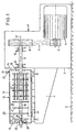
- FIGS. 1 to 3 are in principle so-called horizontal agitator mills. These have in the usual way a stand 1, which is supported on the bottom 2. At the front 3 of the stand 1, a support arm 4 is attached.
- stator an optionally variable speed drive motor 5 is housed, which is provided with a V-belt pulley 6, from which via V-belts 7 and another V-belt pulley 8, a drive shaft 9 is rotationally driven.
- the drive shaft 9 is rotatably supported in the stator 1 by means of several bearings 10.
- a substantially cylindrical grinding container 12 is supported in corresponding receptacles 11.
- the grinding container 12 has a cylindrical wall 13 and is at one, the stator 1 facing end by means of a lid 14 and at the opposite end by means of a bottom 15 are sealed. He encloses a grinding room 16.
- a stirring shaft 18 is arranged in the grinding chamber 16, which passes through the lid 14.
- the grinding chamber 16 is sealed by means of seals 19 between the cover 14 and the shaft 18.
- the shaft 18 is cantilevered, so no longer stored in the region of the bottom 15. It is provided over its length in the grinding chamber 16 with stirring tools 20, which in the present case is agitating disks 21.
- These stirring discs 21 can - as shown in Fig. 1 right - additionally be provided with parallel to the axis 17 extending, arranged in the form of a cage Rrockstäben 22, by means of which the centrifugal forces are increased.
- an inlet pipe 23 is attached, is supplied through the material to be treated.
- On the lower side of the wall 13 of the grinding container 12 is a over a substantial part of the length of the grinding container 12 between the receptacles 11 extending emptying flap 24 is attached.
- the grinding container 12 is provided with an outlet which is configured differently in the various embodiments.
- an outlet which is configured differently in the various embodiments.
- a Mahltosterrorism restraint device as is generally customary in stirred mills, is not provided.
- Mahltosterrorism restraint devices are either sieves in many configurations or so-called separation gap separating devices, as described for example in DE-PS 14 82 391 (corresponding to GB-PS 1 056 257).
- an outlet pipe 25 is disposed in the bottom 15 coaxial with the axis 17, which is provided with an opening 26 on the front side.
- This outlet tube 25 extends into the vicinity of the agitator shaft 18, i. up to the vicinity of the end-side stirrer disk 21.
- a frustoconical, open to the bottom 15 open short pipe section 27 is attached to the bottom 15 leaves a passageway 28 free.
- the outlet tube 25 and the tube portion 27 overlap each other in the direction of the axis 17th
- the agitator shaft 18 is adjacent to its free end, namely, between the two last stirring discs 21, provided with outlet openings 29, which open into a discharge channel 30 in the hollow agitator shaft 18.
- the drainage channel 30 opens in the region of the outside of the grinding container 12 lying end of the agitator shaft 18 from this.
- the stirring rods 22 mentioned may be in the region of the opening 29.
- the agitator shaft 18 is provided in the region of its free end and also there between the two last adjacent stirring discs 21 with outlet openings 31 in an open towards the free end of the agitator shaft 18 outflow channel 32 open. This in turn opens into a arranged in the bottom 15 outlet pipe 33, which leaves only a smallest possible gap with its front side opposite the free end of the agitator shaft 18.
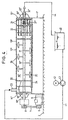
- the embodiment according to FIG. 4 is constructed in the manner of a high-speed drivable mixer. Parts of the embodiments according to FIGS. 1 to 3 are provided with the same reference numerals but with the same reference numerals attached with a double hyphen. From a new description is taken to the extent distance.
- the agitator shaft 18 is mounted on the one hand in a bearing 10" in the region of the cover 14 "and on the other hand in a bearing 10" in the region of the bottom 15 “, ie it is not flying, but mounted at both ends 18 "are provided by the lid 14" on the one hand and the bottom 15 "on the other hand seals 19"
- the agitator shaft 18 is provided with stirrers 20, which may also be stirring discs 21 again;
- the stirring tools 20 may also be designed as classic blade-like mixing tools 39, as also shown in Fig. 4.
- a reservoir 40 is provided, which is connected via a feed line 41 to the inlet port 23.
- this feed line 41 is driven by a motor 42 driven pump 43, by means of which the transport of the material to be treated takes place.
- the drain channel 32 is in turn connected via a return line 44 to the reservoir 40.
- the described continuously operating devices are used, inter alia, for grinding particularly hard material to be treated; these are, for example, silicates and carbides. But they are also used for grinding of low quality bulk goods, such as calcium carbonate, sand (SiO 2 ), mineral Substances and in particular ores used.
- the material to be treated is brought into flowable form in water or another suitable liquid and fed to the grinding container 12 or 12 "through the inlet connection 23 and intensively moved by the high-speed rotating stirring tools 20.
- larger diameter particles enter the respective grinding chamber 16 , 16 "entered.
- two case groups can be distinguished. In one case, coarse particles are introduced with liquid at the beginning of the grinding process and then constantly yielding fine particles, which are crushed. If the coarse particles are partially rubbed off, they must be refilled. In the other case group, coarse particles and fine particles are introduced from the beginning, the coarse particles being concentrated in the grinding chamber.
- the coarse particles that is, the larger diameter particles, have a size of 0.1 to 5.0, and usually 1.0 to 2.0 mm.
- the lower limit of their diameter is 0.1 to 0.3 mm, the usual upper limit at 3.0 to 4.0 mm.
- the fine particles, ie the particles of smaller diameter of the material to be treated should be smaller by a factor of 0.3 to 0.05 than the larger diameter particles used as grinding aid bodies.
- the grinding containers 12 and 12 "are completely filled with the material to be treated.
- the particles of larger diameter contained in the material to be treated are increasingly thrown into the outside area, ie in the direction of the wall 13 or 13" of the grinding container 12, 12 ", ie they are in the grinding chamber 16, 16 "concentrated.
- the particles of larger diameter participate in the grinding process, and indeed they grind as a Mahlosharm the smaller particles, whereby they themselves are also abraded until the desired particle size distribution, is reached. Since the material to be treated exits the grinding chamber 16, 16 "in the region of the axis 17 or the shaft 18 or 18" through the described outlets 25, 29, 31, 31 ", these larger particles remain at least predominantly in the grinding chamber 16 , 16 ".
- the agitator speed on the one hand and the throughput of the treated material on the other hand must be optimally adapted to each other.
- the basic purpose of a control is to achieve a maximum of the power consumption, which in turn is achieved by a high concentration of particles of large diameter in the grinding chamber an increase in the throughput decreases the power consumption, it can be concluded that the proportion of larger diameter particles in the grinding chamber 16 or 16 "has decreased, either by abrasion or by discharge. In this case must be added from particles of larger diameter existing material to be treated. If the power consumption increases again, the problem is solved. If this is not the case, then recognizable larger diameter particles are discharged; In this case, either the throughput of material to be treated must be reduced or, in the presence of a variable-speed drive motor 5, the speed of the agitator shaft 18, 18 "must be increased.
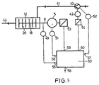
- the control can be performed in the manner shown in FIG.
- a speed detection unit 49 is connected, which outputs a signal corresponding to the speed of a control and regulating device 50.
- the power consumption of the drive motor 5 is recorded by means of a power detection device 51 and given to the control and regulation device 50.
- a flow rate detection device which outputs a the flow rate per unit time corresponding signal to the rule control device 50.
- the throughput detection device 52 may be a tachometer, since the speed is a measure of the throughput in pumps operating without slip or with constant slip.
- the drive motor 5 is associated with a Drehiereverstellvorraum 53, which may be, for example, a frequency converter.
- the drive motor 42 of the pump 43 is associated with a speed adjustment device 54, which may also be a frequency converter.
- the speed of the drive shaft 9, the power of the drive motor 5 and the flow rate of the pump 43 are input as inputs 55, 56, 57 in the control and control device 50.
- a desired value for the power consumption via an input 58 is input to the control and regulating device 50.
- the speed adjustment device 53 of the drive motor 5 and the Drehtogetherverstellvorides the motor 41 of the pump 43 is driven by the above-mentioned control scheme via outputs 59, 60.
- the speed of the agitator is changed; in the second case, the flow rate of the pump 43 is changed.
Description
Die Erfindung betrifft ein Verfahren zum kontinuierlich autogenen Mahlen eines fließfähigen, unlösliche Partikel unterschiedlichen Durchmessers enthaltenden Behandlungsgutes nach dem Oberbegriff des Anspruches 1, und eine Vorrichtung zur Durchführung des Verfahrens nach dem Oberbegriff des Anspruches 7.The invention relates to a method for continuously autogenous grinding of a flowable, insoluble particles of different diameter containing material to be treated according to the preamble of
Das Mahlen von besonders harten Materialien, wie Silicaten und Carbiden ist aufwendig. Es ist durch Benutzung in der Praxis bekannt geworden, hierzu Rührwerksmühlen einzusetzen, die jeweils einen zylindrischen Behälter aufweisen, in dem konzentrisch ein hochtourig antreibbares Rührwerk angeordnet ist. Der Mahlbehälter ist zumindest im wesentlichen mit Mahlhilfskörpern gefüllt. Das Behandlungsgut wird in fließfähiger Form, beispielsweise also mit Wasser aufgeschlämmt, dem Behälter an einem Ende zugeführt und verläßt den Behälter am anderen Ende. Das Gemisch aus Behandlungsgut und Mahlhilfskörpern wird durch das Rührwerk in eine intensive Bewegung versetzt, so daß ein intensives Mahlen stattfindet. Im Bereich des Mahlgut-Auslasses muß eine Mahlhilfskörper-Rückhaltevorrichtung vorgesehen sein, mittels derer die Mahlhilfskörper vom Behandlungsgut getrennt werden können, so daß letzteres mahlhilfskörperfrei austreten kann. Beim Mahlen extrem harter Partikel ist der Verschleiß der Mahlhilfskörper groß. Wenn dagegen geringwertige Mahlgüter als Massenprodukte gemahlen werden, dann sind - auch wenn der Mahlhilfskörperverschleiß nicht allzu groß ist - die Kosten des Mahlhilfskörperverschleisses im Vergleich zum Wert des Mahlgutes nicht tragbar. Darüber hinaus ist die Gefahr sehr groß, daß die Mahlhilfskörper-Rückhalte-vorrichtung durch noch zu große Mahlgutpartikel und/oder verschlissene Mahlhilfskörper zugesetzt wird, was zumindest zu Betriebsstörungen oder auch zu einer teilweisen Zerstörung der Rührwerksmühle führen kann. Diese Gefahr besteht ganz besonders dann, wenn mit hohen Durchsätzen an Behandlungsgut, also entsprechend hohen Strömungsgeschwindigkeiten des Behandlungsgutes in der Rührwerksmühle gearbeitet wird.The grinding of particularly hard materials, such as silicates and carbides is expensive. It has become known through use in practice to use this agitator mills, each having a cylindrical container in which a high-speed drivable agitator is arranged concentrically. The grinding container is at least substantially filled with Mahlhilfskörpern. The material to be treated is in a flowable form, for example slurried with water, fed to the container at one end and leaves the container at the other end. The mixture of treated and Mahlhilfskörpern is mixed by the agitator in an intensive movement, so that an intensive grinding takes place. In the area of the grinding material outlet, a grinding aid body restraint device must be provided by means of which the auxiliary grinding bodies can be separated from the material to be treated, so that the latter can emerge without the aid of a grinding aid. When grinding extremely hard particles, the wear of Mahlhilfskörper is large. If, on the other hand, low-grade millbases are mass-milled, even if the auxiliary grinding tool wear is not too great, the costs of grinding auxiliary body wear are not sustainable compared to the value of the millbase. In addition, the risk is very great that the Mahlhilfskörper retaining device is added by still too large Mahlgutpartikel and / or worn Mahlhilfskörper, which can lead to at least malfunction or even partial destruction of the agitator mill. This danger is especially true when working with high throughputs of items to be treated, ie correspondingly high flow rates of the material to be treated in the agitator mill.
Aus der EP 0 247 895 A und der EP 0 367 403 A ist jeweils eine Vorrichtung und ein Verfahren zum autogenen Mahlen von harten Feststoffen gemäß den Oberbegriffen der Ansprüche 1 bzw. 7 bekannt. Eingesetzt wird eine Rührwerksmühle mit einem eine Wand und einen Boden aufweisenden Mahlbehälter. Am oberen Rand der Wand des Mahlraums ist ein zylindrisches Sieb als Rückhaltevorrichtung vorgesehen. Das Behandlungsgut wird dem Mahlraum von unten durch den Boden zugeführt und oben durch das den Mahlraum einhüllende Sieb entnommen. Durch dieses Sieb werden große Partikel zurückgehalten, während Behandlungsgut mit zu Pulver gemahlenen Partikeln austreten kann. Es besteht eine erhebliche Gefahr des Zusetzens des Siebes und eines erheblichen Siebverschleisses. Im übrigen nehmen die Partikel größeren Durchmessers, die vor dem Sieb sitzen, kaum noch am autogenen Mahlprozeß teil.EP 0 247 895 A and EP 0 367 403 A each disclose an apparatus and a method for autogenous grinding of hard solids according to the preambles of
Aus der DE 34 31 636 C2 (entspr. EP 0 219 740 B1) ist eine Ringspalt-Kugelmühle zum kontinuierlichen Feinzerkleinern, insbesondere von mineralischen Hartstoffen, mit einem geschlossenen Mahlbehälter bekannt, in dem ein Rotor angeordnet ist, dessen Außenfläche mit der Innenfläche des Mahlbehälters einen Mahlspalt begrenzt. In dem Mahlspalt sind sogenannte Mahlperlen, d.h. Mahlhilfskörper, angeordnet, die aus dem gleichen Material wie das zu zerkleinernde Behandlungsgut bestehen können. Das Oberteil und das Unterteil des Rotors verjüngen sich in entgegengesetzten Richtungen. Aufgrund der doppelt konischen Ausgestaltung des Mahlspaltes wird eine Austragung der Mahlhilfskörper mit dem Behandlungsgut durch eine Auslaßöffnung und damit eine Reduzierung der Mahlhilfskörpermenge bzw. der Mahlwirkung verhindert. Dies ist darauf zurückzuführen, daß ein vorgegebener Mahlhilfskörper-Überschuß sich in der radialen ringförmigen Kammer am oberen Ende des Mahlspaltes, d.h. im Bereich des größten Rotordurchmessers, sammelt, und dort eine schwimmende Sperrschicht bildet, die die aktiven Mahlhilfskörper im Mahlspalt zurückhält, ohne nach der Art eines Siebes oder dergleichen den Austritt des feinstgemahlenen Behandlungsgutes aus dem Mahlspalt in Richtung der Auslaßöffnung zu behindern. Eine nachträgliche Trennung von Mahlhilfskörpern und Behandlungsgut entfällt somit. Dies gilt allerdings nur bei niedrigen Durchsätzen, d.h. bei geringer Strömungsgeschwindigkeit des gemahlenen Behandlungsgutes im Mahlspalt. Bei größeren Durchsätzen und entsprechend höheren Strömungsgeschwindigkeiten des Behandlungsgutes im Mahlspalt werden die Mahlhilfskörper mit ausgetragen, so daß hierbei auch eine nachträgliche Trennung von Mahlhilfskörpern und Behandlungsgut notwendig ist. Die vorstehend angesprochenen Probleme des Mahlkörperverschleisses bestehen hierbei im übrigen auch.From DE 34 31 636 C2 (corresponding to EP 0 219 740 B1) an annular gap ball mill for continuous comminuting, in particular mineral hard materials, with a closed grinding container is known, in which a rotor is arranged, whose outer surface with the inner surface of the grinding container limited a grinding gap. In the grinding gap, so-called milling beads, i. Mahlhilfskörper arranged, which may consist of the same material as the material to be crushed. The top and bottom of the rotor taper in opposite directions. Due to the double-conical configuration of the grinding gap, a discharge of Mahlhilfskörper with the material to be treated by an outlet opening and thus a reduction in Mahlhilfskörpermenge or the grinding action is prevented. This is because a given grinding aid excess is found in the radial annular chamber at the top of the grinding gap, i. in the region of the largest rotor diameter, collects, and there forms a floating barrier layer, which retains the active Mahlhilfskörper in the grinding gap without hindering the emergence of finely ground material to be treated from the grinding gap in the direction of the outlet opening in the manner of a sieve or the like. A subsequent separation of Mahlhilfskörpern and treated so deleted. However, this only applies at low flow rates, i. at low flow rate of the ground material to be treated in the grinding gap. For larger throughputs and correspondingly higher flow rates of the material to be treated in the grinding gap Mahlhilfskörper be discharged, so that in this case also a subsequent separation of Mahlhilfskörpern and Behandlungsgut is necessary. The above-mentioned problems of Mahlkörperverschleisses here are incidentally also.
Aus der EP 0 278 041 A1 ist eine vertikale Rührwerksmühle bekannt, die einen vertikalen zylindrischen Behälter mit einem koaxial in diesem angeordneten drehantreibbaren Rührwerk aufweist. Die Rührwerksmühle ist zu einem Teil mit ihren Mahlraum bildenden beziehungsweise begrenzenden Mahlhilfskörpern gefüllt. Oberhalb dieses Mahlraums sind ein Zulaufstutzen für Behandlungsgut und ein Auslass für behandeltes Behandlungsgut angeordnet. Eine Auslassöffnung für Mahlhilfskörper ist im unteren Bereich des Behälters vorgesehen. Es wird ein Fluid, nämlich Luft oder Flüssigkeit, von unten zugeführt, durch die nach Art einer Windsichtung das fein gemahlene Behandlungsgut nach oben ausgetragen wird.From EP 0 278 041 A1 a vertical agitator mill is known, which has a vertical cylindrical container with a coaxially arranged in this rotary drivable agitator. The agitator mill is filled to a part with their Mahlraumbildenden or limiting Mahlhilfskörpern. Above this grinding chamber, an inlet nozzle for material to be treated and an outlet for treated material to be treated are arranged. An outlet opening for Mahlhilfskörper is provided in the lower region of the container. There is a fluid, namely air or liquid supplied from below, through which the finely ground material to be treated is discharged upward in the manner of an air classification.
Der Erfindung liegt die Aufgabe zugrunde, ein Verfahren und eine Vorrichtung der eingangs angegebenen Art zu schaffen, die ein kontinuierliches autogenes Mahlen von Behandlungsgut in besonders einfacher Weise auch bei hohen Durchsätzen ohne Betriebsstörungen ermöglichen.The invention has for its object to provide a method and an apparatus of the type described, which allow a continuous autogenous grinding of material to be treated in a particularly simple manner, even at high throughputs without malfunction.
Diese Aufgabe wird bei einem Verfahren der eingangs angegebenen Art durch die Merkmale des Anspruches 1 gelöst. Sie wird weiterhin bei einer Vorrichtung der eingangs genannten Art durch die Merkmale des Anspruches 7 gelöst. Der Kern der Erfindung besteht darin, daß die Partikel mit größerem Durchmesser im Mahlraum aufkonzentriert und dort einerseits gleichsam als Mahlhilfskörper zur Mahlung der Partikel kleineren Durchmessers verwendet und andererseits hierbei selber an ihrer Außenseite abgerieben werden. Es werden also keine eigenständigen artfremden Mahlhilfskörper verwendet; weiterhin ist keine Mahlhitfskörper-Rückhaltevorrichtung notwendig, da die gleichsam als Mahlhilfskörper eingesetzten Partikel im Mahlraum verbleiben. Betriebsstörungen aufgrund des Zusetzens einer Mahlhilfskörper-Rückhaltevorrichtung können also nicht mehr auftreten. Das Behandlungsgut wird klassiert und zwar in Partikel größeren Durchmessers, die zum Mahlen eingesetzt werden und in Partikel kleineren Durchmessers, die gemahlen werden sollen. Die Partikel größeren Durchmesser werden in den Mahlraum der Rührwerksmühle eingegeben und verbleiben dort. Anschließend wird zum Mahlen nur das vorklassierte Behandlungsgut mit Partikeln kleineren Durchmessers durch den Mahlraum geführt.This object is achieved in a method of the type specified by the features of
Zahlreiche zum Teil erfinderische Ausgestaltungen ergeben sich aus den Unteransprüchen.Numerous partly inventive embodiments emerge from the subclaims.
Weitere Merkmale, Vorteile und Einzelheiten der Erfindung ergeben sich aus der nachfolgenden Beschreibung von fünf Ausführungsbeispielen anhand der Zeichnung. Es zeigt
- Fig. 1
- eine erste nach Art einer Rührwerksmühle aufgebaute Ausführungsform einer Vorrichtung zum autogenen Mahlen im Vertikalschnitt in schematischer Darstellung,
- Fig. 2
- eine zweite nach Art einer Rührwerksmühle aufgebaute Ausführungsform einer Vorrichtung zum autogenen Mahlen im Vertikalschnitt in schematischer Darstellung,
- Fig. 3
- eine dritte nach Art einer Rührwerksmühle aufgebaute Ausführungsform einer Vorrichtung zum autogenen Mahlen im Vertikalschnitt in schematischer Darstellung,
- Fig. 4
- eine vierte nach Art eines Ringmischers aufgebaute Ausführungsform einer Vorrichtung zum autogenen Mahlen im Vertikalschnitt in schematischer Darstellung und
- Fig. 5
- ein Regelungs-Blockschaltbild für eine Rührwerksmühle.
- Fig. 1
- a first constructed in the manner of a stirred mill embodiment of a device for autogenous grinding in vertical section in a schematic representation,
- Fig. 2
- a second embodiment of a device for autogenous grinding constructed in the manner of a stirred mill in a vertical section in a schematic representation,
- Fig. 3
- a third embodiment of a device for autogenous grinding constructed in the manner of an agitator mill in a vertical section in a schematic representation,
- Fig. 4
- a fourth constructed in the manner of a ring mixer embodiment of a device for autogenous grinding in vertical section in a schematic representation and
- Fig. 5
- a control block diagram for an agitator mill.
Bei den Ausführungsformen nach den Fig. 1 bis 3 handelt es sich im Grundsatz um sogenannte liegende Rührwerksmühlen. Diese weisen in üblicher Weise einen Ständer 1 auf, der auf dem Boden 2 abgestützt ist. An der Vorderseite 3 des Ständers 1 ist ein Tragarm 4 angebracht.The embodiments according to FIGS. 1 to 3 are in principle so-called horizontal agitator mills. These have in the usual way a
Im Ständer ist ein gegebenenfalls drehzahlregelbarer Antriebsmotor 5 untergebracht, der mit einer Keilriemenscheibe 6 versehen ist, von der über Keilriemen 7 und eine weitere Keilriemenscheibe 8 eine Antriebswelle 9 drehantreibbar ist. Die Antriebswelle 9 ist im Ständer 1 mittels mehrerer Lager 10 drehbar gelagert.In the stator an optionally variable
Auf dem Tragarm 4 ist in entsprechenden Aufnahmen 11 ein im wesentlichen zylindrischer Mahlbehälter 12 abgestützt. Der Mahlbehälter 12 weist eine zylindrische Wand 13 auf und ist an einem, dem Ständer 1 zugewandten Ende mittels eines Deckels 14 und am gegenüberliegenden Ende mittels eines Bodens 15 verschlässen. Er umschließt einen Mahlraum 16.On the
Konzentrisch zur gemeinsamen Mittel-LängsAchse 17 von Mahlbehälter 12 und Antriebswelle 9 ist im Mahlraum 16 eine Rührwerks-Welle 18 angeordnet, die den Deckel 14 durchsetzt. Der Mahlraum 16 ist mittels Dichtungen 19 zwischen dem Deckel 14 und der Welle 18 abgedichtet. Die Welle 18 ist fliegend gelagert, also im Bereich des Bodens 15 nicht mehr gelagert. Sie ist über ihre Länge im Mahlraum 16 mit Rührwerkzeugen 20 versehen, bei denen es sich im vorliegenden Fall um Rührscheiben 21 handelt. Diese Rührscheiben 21 können - wie in Fig. 1 rechts dargestellt - zusätzlich mit sich parallel zur Achse 17 erstreckenden, in Form eines Käfigs angeordneten Rührstäben 22 versehen sein, mittels derer die Zentrifugalkräfte erhöht werden.Concentric to the common central
Am Mahlbehälter 12 ist - benachbart zum Dekkel 14 - ein Zulaufstutzen 23 angebracht, durch den zu behandelndes Gut zugeführt wird. An der unten liegenden Seite der Wand 13 des Mahlbehälters 12 ist eine sich über einen wesentlichen Teil der Länge des Mahlbehälters 12 zwischen den Aufnahmen 11 erstreckende Entleerungsklappe 24 angebracht.At the grinding container 12 - adjacent to the lid 14 - an
Bei allen Ausführungsformen ist der Mahlbehälter 12 mit einem Auslaß versehen, der bei den verschiedenen Ausführungsformen unterschiedlich ausgestaltet ist. Gemeinsam ist allen Auslässen, daß eine Mahlhilfskörper-Rückhaltevorrichtung, wie sie bei Rührwerksmühlen generell üblich ist, nicht vorgesehen ist. Bei derartigen Mahlhilfskörper-Rückhaltevorrichtungen handelt es sich entweder um Siebe in vielerlei Ausgestaltungen oder um sogenannte Trennspalt-Abtrennvorrichtungen, wie sie beispielsweise in der DE-PS 14 82 391 (entspr. GB-PS 1 056 257) beschrieben sind.In all embodiments, the grinding
Bei der Ausführungsform nach Fig. 1 ist im Boden 15 koaxial zur Achse 17 ein Auslaß-Rohr 25 angeordnet, das stirnseitig mit einer Öffnung 26 versehen ist. Dieses Auslaß-Rohr 25 reicht bis in die Nähe der Rührwerks-Welle 18, d.h. bis in die Nähe der endseitigen Rührscheibe 21. An dieser endseitigen Rührscheibe 21 ist ein beispielsweise kegelstumpfförmiger, zum Boden 15 hin offener kurzer Rohr-Abschnitt 27 angebracht, der zum Boden 15 einen Durchtrittskanal 28 frei läßt. Das Auslaß-Rohr 25 und der Rohr-Abschnitt 27 überdecken einander in Richtung der Achse 17.In the embodiment of FIG. 1, an
Bei der Ausführungsform nach Fig. 2 ist die Rührwerks-Welle 18 benachbart zu ihrem freien Ende, und zwar zwischen den beiden letzten Rührscheiben 21, mit Auslaß-Öffnungen 29 versehen, die in einen Ablaufkanal 30 in der hohlen Rührwerks-Welle 18 einmünden. Der Ablaufkanal 30 mündet im Bereich des außerhalb des Mahlbehälters 12 liegenden Endes der Rührwerkswelle 18 aus dieser aus. Zur Verstärkung des Zentrifugaleffektes können im Bereich der Öffnung 29 die erwähnten Rührstäbe 22 sein.In the embodiment of Fig. 2, the
Bei der Ausführungsform nach Fig. 3 ist die Rührwerks-Welle 18 im Bereich ihres freien Endes und auch dort zwischen den beiden letzten einander benachbarten Rührscheiben 21 mit Auslaß-Öffnungen 31 versehen, die in einen zum freien Ende der Rührwerks-Welle 18 hin offenen Ablaufkanal 32 einmünden. Dieser mündet wiederum in ein im Boden 15 angeordnetes Auslaß-Rohr 33, das mit seiner Stirnseite gegenüber dem freien Ende der Rührwerks-Welle 18 nur einen möglichst kleinen Spalt frei läßt.In the embodiment of FIG. 3, the
Während die Ausführungsformen nach den Fig. 1 bis 3 Rührwarksmühlen sind, ist die Ausführungsform nach Fig. 4 nach Art eines hochtourig antreibbaren Mischers aufgebaut Mit den Ausführungsformen nach den Fig. 1 bis 3 funktionell gleichartige Teile werden mit den gleichen Bezugsziffern versehen, denen jedoch ein hochgesetzter Doppelstrich beigefügt wird. Von einer erneuten Beschreibung wird insoweit Abstand genommen.Whereas the embodiments according to FIGS. 1 to 3 are stirred mills, the embodiment according to FIG. 4 is constructed in the manner of a high-speed drivable mixer. Parts of the embodiments according to FIGS. 1 to 3 are provided with the same reference numerals but with the same reference numerals attached with a double hyphen. From a new description is taken to the extent distance.
Die Rührwerks-Welle 18" ist einerseits in einem Lager 10" im Bereich des Deckels 14" und andererseits in einem Lager 10" im Bereich des Bodens 15" gelagert, d.h. sie ist nicht fliegend, sondern beidendig gelagert. Am Durchtritt der Rührwerks-Welle 18" durch den Deckel 14" einerseits und den Boden 15" andererseits sind Dichtungen 19" vorgesehen. Die Rührwerks-Welle 18" ist mit Rührwerkzeugen 20 versehen, bei denen es sich ebenfalls wieder um Rührscheiben 21 handeln kann; die Rührwerkzeuge 20 können aber auch als klassische schaufelartige Mischwerkzeuge 39 ausgebildet sein, wie es ebenfalls in Fig. 4 dargestellt ist.The
Benachbart zum Deckel 14" ist ein Zulaufstutzen 23 vorgesehen, der in den Mahlraum 16" einmündet.Adjacent to the
Benachbart zum Boden 15", und zwar auch dort zwischen den beiden letzten Rührscheiben 21, sind in der Rührwerks-Welle 18" Auslaß-Öffnungen 31" ausgebildet, die in einen in der Rührwerksmühle ausgebildeten Ablaufkanal 32" münden, der wiederum hinter dem deckelseitigen Lager 10" austritt. Auch hier können selbstverständlich die geschilderten Rührstäbe 22 vorgesehen werden.Adjacent to the bottom 15 ", and there also between the last two stirring
Nur in Fig. 4 ist angedeutet, daß das Behandlungsgut dem Behandlungsprozeß mehrfach zugeführt wird. Hierzu ist ein Vorratsbehälter 40 vorgesehen, der über eine Zuführleitung 41 mit dem Zulaufstutzen 23 verbunden ist. In diese Zuführleitung 41 ist eine von einem Motor 42 angetriebene Pumpe 43 geschaltet, mittels derer der Transport des Behandlungsguts erfolgt. Der Ablaufkanal 32" ist wiederum über eine Rückführleitung 44 mit dem Vorratsbehälter 40 verbunden.Only in Fig. 4 is indicated that the material to be treated is fed to the treatment process several times. For this purpose, a
Die geschilderten kontinuierlich arbeitenden Vorrichtungen werden u.a. zum Mahlen von besonders hartem Behandlungsgut eingesetzt; hierbei handelt es sich beispielsweise um Silicate und Carbide. Sie werden aber auch zum Mahlen von geringwertigen Massengütem, wie Kalziumkarbonat, Sand (SiO2), mineralischen Stoffen und insbesondere Erzen, eingesetzt. Das Behandlungsgut wird in Wasser oder einer anderen geeigneten Flüssigkeit in fließfähige Form gebracht und dem Mahlbehälter 12 bzw. 12" durch den Zulaufstutzen 23 zugeführt und durch die hochtourig umlaufenden Rührwerkzeuge 20 intensiv bewegt. Zu Beginn eines Mahtvorgangs werden Partikel größeren Durchmessers in den jeweiligen Mahlraum 16, 16" eingegeben. Hierbei können zwei Fallgruppen unterschieden werden. In einem Fall werden zu Beginn des Mahlprozesses grobe Partikel mit Flüssigkeit eingegeben und dann Feinpartikel laufend nachgegeben, die zerkleinert werden. Wenn die groben Partikel teilweise abgerieben sind, müssen diese wieder nachgefüllt werden. In der anderen Fallgruppe werden von Anfang an grobe Partikel und feine Partikel eingegeben, wobei die groben Partikel im Mahlraum aufkonzentriert werden.The described continuously operating devices are used, inter alia, for grinding particularly hard material to be treated; these are, for example, silicates and carbides. But they are also used for grinding of low quality bulk goods, such as calcium carbonate, sand (SiO 2 ), mineral Substances and in particular ores used. The material to be treated is brought into flowable form in water or another suitable liquid and fed to the grinding
Die groben Partikel, also die Partikel größeren Durchmessers, haben eine Größe von 0,1 bis 5,0 und üblicherweise von 1,0 bis 2,0 mm. Die untere Grenze ihres Durchmessers liegt bei 0,1 bis 0,3 mm, die übliche Obergrenze bei 3,0 bis 4,0 mm. Die feinen Partikel, also die Partikel kleineren Durchmessers des Behandlungsgutes sollten um den Faktor 0,3 bis 0,05 kleiner sein als die gleichsam als Mahlhilfskörper eingesetzten Partikel größeren Durchmessers. Die Mahlbehälter 12 bzw. 12" sind mit dem Behandlungsgut vollständig gefüllt. Die im Behandlungsgut enthaltenen Partikel größeren Durchmessers werden verstärkt in den Außenbereich, d.h. in Richtung zur Wand 13 bzw. 13" des Mahlbehälters 12, 12" geschleudert, sie werden also im Mahlraum 16, 16" aufkonzentriert. Die Partikel größeren Durchmessers nehmen am Mahlprozeß teil, und zwar mahlen sie gleichsam als Mahlhilfskörper die kleineren Partikel, wobei sie selber ebenfalls abgerieben werden, bis die angestrebte Partikelgrößenverteilung, erreicht ist. Da das Behandlungsgut im Bereich der Achse 17 bzw. der Welle 18 bzw. 18" durch die geschilderten Auslässe 25, 29, 31, 31", 34, aus dem Mahlraum 16, 16" austritt, verbleiben diese größeren Partikel zumindest überwiegend im Mahlraum 16, 16". Wenn das Behandlungsgut mehrfach durch den Mahlraum 16 bzw. 16" geführt wird, dann sind am Ende auch die größeren Partikel zumindest teilweise zerkleinert. Soweit Partikel größeren Durchmessers mit dem behandelten Mahlgut ausgetragen werden, können sie nicht eine Rückhaltevorrichtung zusetzen, da eine solche nicht vorhanden ist. Alle Auslässe weisen eine minimale Weite a auf, die deutlich größer als die Partikel größeren Durchmessers ist. Die minimale Weite eines Auslasses beträgt mindestens 5 mm in der Regel min destens 10 mm.The coarse particles, that is, the larger diameter particles, have a size of 0.1 to 5.0, and usually 1.0 to 2.0 mm. The lower limit of their diameter is 0.1 to 0.3 mm, the usual upper limit at 3.0 to 4.0 mm. The fine particles, ie the particles of smaller diameter of the material to be treated, should be smaller by a factor of 0.3 to 0.05 than the larger diameter particles used as grinding aid bodies. The grinding
Wenn bei einer Kreislaufmahlung das im Vorratsbehälter 40 befindliche Behandlungsgut bis auf eine vorgegebene Partikelgrößenverteilung gemahlen ist, dann kann die im Vorratsbehälter 40 befindliche Charge ausgewechselt werden, wobei die im Mahlraum 16 bzw. 16" befindliche Menge an Behandlungsgut nicht mit ausgetauscht wird, da in diesem noch ein höherer Anteil an Partikeln größeren Durchmessers enthalten ist. Diese Maßnahmen zum Mehrfachdurchlauf von Behandlungsgut durch den Mahlraum 16 bzw. 16" können in gleicher Weise auch bei allen anderen Ausführungsformen angewendet werden.If in a Kreislaufmahlung the material in the
Damit eine starke Aufkonzentration der Partikel größeren Durchmessers im Mahlraum erfolgt, müssen die Rührwerksdrehzahl einerseits und der Durchsatz des Behandlungsgutes andererseits einander optimal angepaßt werden. Als Kennzahl hierfür kann die Leistungsaufnahme des Antriebsmotors 5 bzw. 5" oder aber dessen Stromaufnahme dienen. Grundsätzliches Ziel einer Regelung ist es, ein Maximum der Leistungsaufnahme zu erreichen. Dies wird wiederum erreicht durch eine hohe Konzentration von Partikeln großen Durchmessers im Mahlraum. Wenn bei einer Steigerung des Durchsatzes die Leistungsaufnahme abnimmt, so ist daraus zu schließen, daß der Anteil an Partikeln größeren Durchmessers im Mahlraum 16 bzw. 16" abgenommen hat und zwar entweder durch Abrieb oder aber durch Austrag. In diesem Fall muß aus Partikeln größeren Durchmessers bestehendes Behandlungsgut zugegeben werden. Wenn hierbei die Leistungsaufnahme wieder zunimmt, ist das Problem gelöst. Wenn dies nicht der Fall ist, dann werden erkennbar Partikel größeren Durchmessers ausgetragen; in diesem Fall muß entweder der Durchsatz an Behandlungsgut reduziert werden, oder aber bei Vorhandensein eines drehzahlregelbaren Antriebsmotors 5 die Drehzahl der Rührwerkswelle 18, 18" erhöht werden.In order for a strong concentration of particles larger diameter in the grinding chamber, the agitator speed on the one hand and the throughput of the treated material on the other hand must be optimally adapted to each other. The basic purpose of a control is to achieve a maximum of the power consumption, which in turn is achieved by a high concentration of particles of large diameter in the grinding chamber an increase in the throughput decreases the power consumption, it can be concluded that the proportion of larger diameter particles in the grinding
Konkret kann die Regelung in der in Fig. 5 dargestellten Weise durchgeführt werden. Mit der Antriebswelle 9 und damit mit der Rührwerks-Welle 18 ist eine Drehzahl-Erfassungseinheit 49 verbunden, die ein der Drehzahl entsprechendes Signal auf eine Regel- und Steuereinrichtung 50 gibt. Es wird weiterhin die Leistungsaufnahme des Antriebsmotors 5 mittels eines Leistungs-Erfassungsgerätes 51 aufgenommen und an die Regel- und Steuereinrichtung 50 gegeben. Es ist weiterhin der Pumpe 43 ein Durchsatz-Erfassungseinrichtung zugeordnet, die ein dem Durchsatz pro Zeiteinheit entsprechendes Signal an die Regel-Steuereinrichtung 50 abgibt. Bei der Durchsatz-Erfassungseinrichtung 52 kann es sich um ein Drehzahlmeßgerät handeln, da bei schlupffrei oder mit konstantem Schlupf arbeitenden Pumpen die Drehzahl ein Maß für den Durchsatz ist. Weiterhin ist dem Antriebsmotor 5 eine Drehzahlverstellvorrichtung 53 zugeordnet, bei der es sich beispielsweise um einen Frequenzumrichter handeln kann. In gleicher Weise ist dem Antriebsmotor 42 der Pumpe 43 eine Drehzahlverstellvorrichtung 54 zugeordnet, bei der es sich ebenfalls um einen Frequenzumrichter handeln kann. Die Drehzahl der Antriebswelle 9, die Leistungsaufnahme des Antriebsmotors 5 und der Durchsatz der Pumpe 43 werden als Eingänge 55, 56, 57 in die Regel- und Steuereinrichtung 50 eingegeben.Concretely, the control can be performed in the manner shown in FIG. With the
Weiterhin wird ein Sollwert für die Leistungsaufnahme über einen Eingang 58 in die Regel- und Steuereinrichtung 50 eingegeben. Von der Regel- und Steuereinrichtung 50 wird nach dem vorstehend angegebenen Regelungsschema über Ausgänge 59, 60 die Drehzahlverstellvorrichtung 53 des Antriebsmotors 5 und die Drehzählverstellvorrichtung des Motors 41 der Pumpe 43 angesteuert. Im ersten Fall wird die Drehzahl des Rührwerks geändert; im zweiten Fall wird der Durchsatz der Pumpe 43 geändert.Furthermore, a desired value for the power consumption via an
Claims (18)
- A method for the continuous autogenous grinding of stock formed with liquid to be free-flowing, containing insoluble particles of varying diameter,
wherein the stock is supplied to a grinding chamber (16) located in a grinding receptacle (12, 12") which has a wall (13, 13") and a bottom (15, 15"), where it is set rotating concentrically of a horizontal axis (17), and wherein insoluble particles of greater diameter in the grinding chamber (16) are increasingly centrifuged towards the wall and thus concentrated superproportionally as compared to particles of smaller diameter,
characterized
in that at an end of the grinding chamber (16) completely filled with stock and closed by a lid (14, 14") the stock is discharged from the grinding chamber (16) through an outlet aperture in the vicinity of the axis (17), the minimum width a of the outlet aperture being substantially greater than the particles of greater diameter. - A method according to claim 1, characterized in that the particles of smaller diameter are smaller than the particles of greater diameter by the factor 0.3 to 0.05.
- A method according to claim 1 or 2, characterized in that predominantly particles of greater diameter are supplied to the grinding chamber (16) at the beginning of a grinding operation, particles of smaller diameter being predominantly supplied during the ensuing grinding operation.
- A method according to one of claims 1 to 3, characterized in that - referred to the axis (17) - stock is supplied to one end of the grinding chamber (16) and is discharged from the grinding chamber (16) at the other end.
- A method according to one of claims 1 to 4, characterized in that the stock is repeatedly run through the grinding chamber (16, 16"').
- A method according to one of claims 1 to 5, characterized in that for the discharge of inorganic particles of higher density and/or greater diameter from the grinding chamber (16), the supply of stock to the grinding chamber (16) is reduced and/or the rotation is increased.
- An apparatus for putting into practice the method according to one of claims 1 to 6, comprising
a horizontally arranged grinding receptacle (12, 12") enclosing a grinding chamber (16), which is free from auxiliary grinding bodies, by means of a wall (13, 13") and a bottom (15, 15");
an agitator unit rotatably disposed in the grinding receptacle (12, 12") concentrically of the axis (17) thereof;
agitator elements (20) attached to the agitator unit; a drive motor (5, 5') coupled with the agitator unit;
at least one stock supply connector (23) opening into the grinding chamber (16) - referred to the axis (17) - at one end of the grinding chamber (16), and at least one outlet (25, 25'''; 29; 31, 31"; 34) arranged at the other end of the grinding chamber (16) for treated stock
characterized
in that the grinding chamber (16, 16) is closed by a lid (14, 14', 14", 14'''); and in that the at least one outlet (25, 25'''; 29; 31,31"; 34) is disposed in the vicinity of the axis (17) and does not comprise an auxiliary grinding body retaining device. - An apparatus according to claim 7, characterized in that the outlet is an outlet pipe (25), which is disposed concentrically of a cantilevered agitator shaft (18) and which is open frontally thereto.
- An apparatus according to claim 8, characterized in that in the direction of the axis (17), the outlet pipe (25) is at least partially covered by a pipe section (27) connected with the agitator shaft (18).
- An apparatus according to claim 8 or 9, characterized in that a passage (28) is formed between the pipe section (27) and an adjacent bottom (15) of the grinding receptacle (12) and/or between the outlet pipe (25) and the agitator shaft (18).
- An apparatus according to one of claims 7 to 10, characterized in that the outlet is formed by at least one outlet aperture (29, 31, 31") provided in an agitator shaft (18, 18") and opening into a discharge conduit (30, 32, 32") located in the agitator shaft (18, 18").
- An apparatus according to one of claims 7 to 11, characterized in that at least one agitator element (20) is provided in direct vicinity to an outlet (25; 29; 31, 31"; 34).
- An apparatus according to claims 11 and 12, characterized in that - referred to the axis (17) - at least one agitator element (20) is mounted on the agitator shaft (18, 18") on either side of the at least one outlet aperture (29, 31, 31").
- An apparatus according to one of claims 7 to 13, characterized in that the agitator elements (20) are agitator disks (21).
- An apparatus according to one of claims 7 to 14, in particular according to claim 13, characterized in that agitator rods (22) disposed in the way of a cage approximately parallel to the axis (17) are provided on the agitator elements (20).
- An apparatus according to claim 7, characterized in that the agitator unit is provided with rods (46) in the way of a cup-shaped cage, which extend parallel and concentrically of the axis (17) and to which agitator elements (20) are attached in the way of blades or paddles (48), respectively.
- An apparatus according to claim 7, characterized in that the at least one outlet (25; 29; 31, 31") for treated stock has a minimum width (a) of at least 5 mm and preferably at least 10 mm.
- An apparatus according to one of claims 7 to 17, characterized in that a control unit (50) is provided for the increase of the speed of the agitator unit and/or for the reduction of the supply of stock upon decrease of the power draw of the drive motor (5, 5").
Applications Claiming Priority (3)
| Application Number | Priority Date | Filing Date | Title |
|---|---|---|---|
| DE4432153A DE4432153A1 (en) | 1994-09-09 | 1994-09-09 | Method and device for the continuous autogenous grinding of a flowable material to be treated |
| DE4432153 | 1994-09-09 | ||
| US08/524,639 US5570846A (en) | 1994-09-09 | 1995-09-07 | Method and apparatus for the continuous autogenous grinding of free-flowing stock |
Publications (3)
| Publication Number | Publication Date |
|---|---|
| EP0700724A1 EP0700724A1 (en) | 1996-03-13 |
| EP0700724B1 EP0700724B1 (en) | 2000-01-26 |
| EP0700724B2 true EP0700724B2 (en) | 2005-09-21 |
Family
ID=25939982
Family Applications (1)
| Application Number | Title | Priority Date | Filing Date |
|---|---|---|---|
| EP95113662A Expired - Lifetime EP0700724B2 (en) | 1994-09-09 | 1995-08-31 | Method and apparatus for continously autogenously milling a flowable processing material |
Country Status (8)
| Country | Link |
|---|---|
| US (1) | US5570846A (en) |
| EP (1) | EP0700724B2 (en) |
| JP (1) | JPH0889836A (en) |
| CN (1) | CN1041998C (en) |
| BR (1) | BR9503976A (en) |
| CA (1) | CA2157700A1 (en) |
| DE (1) | DE4432153A1 (en) |
| ZA (1) | ZA957582B (en) |
Families Citing this family (11)
| Publication number | Priority date | Publication date | Assignee | Title |
|---|---|---|---|---|
| DE19528958A1 (en) * | 1995-08-08 | 1997-02-13 | Hoechst Ag | Autogenous grinding of silicon nitride |
| DE19635500B4 (en) * | 1996-09-03 | 2008-01-10 | Zoz Gmbh | Apparatus for the high-energy and / or pulverization of solids and method for its operation |
| EP2488290B2 (en) | 2009-10-15 | 2022-03-30 | Bühler AG | Method and use for comminution |
| DE102010012620A1 (en) * | 2010-03-24 | 2011-09-29 | Siemens Aktiengesellschaft | Method for operating a mill |
| CN102553686B (en) * | 2012-03-15 | 2013-07-24 | 李强 | Shaft-driven ball grinding mill |
| DE102013215257A1 (en) | 2013-08-02 | 2015-02-05 | Wacker Chemie Ag | Process for comminuting silicon and use of comminuted silicon in a lithium-ion battery |
| DE102013021757A1 (en) * | 2013-12-20 | 2015-06-25 | Netzsch Trockenmahltechnik Gmbh | Machine with floating rotor |
| TW201540358A (en) * | 2014-04-29 | 2015-11-01 | Univ Nat Cheng Kung | Exfoliator, exfoliating apparatus and exfoliating method |
| CN106436424B (en) * | 2016-12-19 | 2017-11-10 | 重庆市沃利克环保设备有限公司 | Multi-functional paper/plastic cleaning separation, which is quenched, starches equipment |
| CN110681451A (en) * | 2019-10-18 | 2020-01-14 | 内蒙古超牌建材科技有限公司 | Slurry overflow prevention vertical wet ball mill and slurry overflow prevention control method thereof |
| CN114459222B (en) * | 2022-02-22 | 2023-01-31 | 郑州鼎力新能源设备有限公司 | Be used for saw-dust drying process device |
Citations (2)
| Publication number | Priority date | Publication date | Assignee | Title |
|---|---|---|---|---|
| DE2725685A1 (en) † | 1976-06-09 | 1977-12-15 | Funk Heporaut Kirsti | SHAFT SEAL, ESPECIALLY ON AN AGITATOR OR COLOID MILL |
| EP0278041A1 (en) † | 1987-01-23 | 1988-08-17 | Kubota Ltd. | Vertical grinding mill |
Family Cites Families (19)
| Publication number | Priority date | Publication date | Assignee | Title |
|---|---|---|---|---|
| DE1482391B1 (en) | 1964-06-20 | 1970-08-20 | Draiswerke Gmbh | Agitator mill |
| US3545687A (en) * | 1968-06-27 | 1970-12-08 | Martin Marietta Corp | Media mill |
| US3844490A (en) * | 1972-12-06 | 1974-10-29 | G Schold | Apparatus for dispersing finely divided solid particles in a liquid vehicle |
| DE2827865A1 (en) * | 1978-06-24 | 1980-01-17 | Draiswerke Gmbh | Grinding mill for resinous dispersions - in which cooled shaft rotates spurs meshing with spurs from barrel |
| US4206879A (en) * | 1978-08-10 | 1980-06-10 | Gebrueder Buehler Ag | Agitator mill |
| AT367657B (en) * | 1978-08-24 | 1982-07-26 | Buehler Ag Geb | AGITATOR BALL MILL CONTROL |
| JPS56500384A (en) * | 1979-03-27 | 1981-03-26 | ||
| DE3245825C2 (en) * | 1982-12-10 | 1994-01-27 | Buehler Ag Geb | Agitator mill |
| DE3345680A1 (en) * | 1983-12-16 | 1985-06-20 | Gebrüder Netzsch, Maschinenfabrik GmbH & Co, 8672 Selb | AGITATOR MILL |
| DE3431636C1 (en) | 1984-08-29 | 1985-10-17 | Reimbold & Strick GmbH & Co, 5000 Köln | Annular gap ball mill |
| DD227339B5 (en) * | 1984-10-15 | 1996-04-04 | Petzholdt Heidenauer Maschinen | agitating mill |
| DE3437866A1 (en) * | 1984-10-16 | 1986-04-17 | Basf Farben + Fasern Ag, 2000 Hamburg | DISPERSION METHOD AND STIRRING MILL FOR ITS IMPLEMENTATION |
| US5158239A (en) * | 1984-10-16 | 1992-10-27 | Basf Lacke & Farben Ag | Dispersing process and stirred ball mill for carrying out this process |
| US4775393A (en) * | 1985-04-11 | 1988-10-04 | The Standard Oil Company | Autogenous attrition grinding |
| CN85106019B (en) | 1985-08-27 | 1987-10-28 | 赖博尔德-斯特里克股份公司 | Annular gap type ball grinder |
| DE3614980C1 (en) * | 1986-05-02 | 1993-05-27 | Draiswerke Gmbh | Control device for a agitator mill |
| US4932166A (en) * | 1986-05-30 | 1990-06-12 | The Carborundum Company | Inert autogenous attrition grinding |
| DE4025987C2 (en) * | 1990-08-16 | 1998-04-09 | Buehler Ag | Agitator mill |
| DE9209222U1 (en) * | 1992-07-09 | 1992-09-24 | Tsay, Chung-Shyong, Lu-Chou Country, Taipeh, Tw |
-
1994
- 1994-09-09 DE DE4432153A patent/DE4432153A1/en not_active Withdrawn
-
1995
- 1995-08-31 EP EP95113662A patent/EP0700724B2/en not_active Expired - Lifetime
- 1995-09-07 CA CA002157700A patent/CA2157700A1/en not_active Abandoned
- 1995-09-07 US US08/524,639 patent/US5570846A/en not_active Expired - Lifetime
- 1995-09-08 ZA ZA957582A patent/ZA957582B/en unknown
- 1995-09-08 CN CN95116242A patent/CN1041998C/en not_active Expired - Lifetime
- 1995-09-08 BR BR9503976A patent/BR9503976A/en not_active Application Discontinuation
- 1995-09-08 JP JP7231508A patent/JPH0889836A/en active Pending
Patent Citations (2)
| Publication number | Priority date | Publication date | Assignee | Title |
|---|---|---|---|---|
| DE2725685A1 (en) † | 1976-06-09 | 1977-12-15 | Funk Heporaut Kirsti | SHAFT SEAL, ESPECIALLY ON AN AGITATOR OR COLOID MILL |
| EP0278041A1 (en) † | 1987-01-23 | 1988-08-17 | Kubota Ltd. | Vertical grinding mill |
Also Published As
| Publication number | Publication date |
|---|---|
| BR9503976A (en) | 1996-09-24 |
| US5570846A (en) | 1996-11-05 |
| EP0700724A1 (en) | 1996-03-13 |
| EP0700724B1 (en) | 2000-01-26 |
| CA2157700A1 (en) | 1996-03-10 |
| JPH0889836A (en) | 1996-04-09 |
| CN1119556A (en) | 1996-04-03 |
| ZA957582B (en) | 1996-04-15 |
| DE4432153A1 (en) | 1996-03-14 |
| CN1041998C (en) | 1999-02-10 |
Similar Documents
| Publication | Publication Date | Title |
|---|---|---|
| EP0369149B1 (en) | Stirring ball mill | |
| EP2178642B1 (en) | Stirrer mill | |
| DE4432200C1 (en) | Agitator mill | |
| DE2848479A1 (en) | RUBBER BALL MILL | |
| EP0173271B1 (en) | Annular gap pebble mill | |
| EP1468739A1 (en) | Agitator ball mill | |
| EP2327479A1 (en) | Stirring ball mill | |
| EP2178643B1 (en) | Stirrer mill | |
| EP0700724B2 (en) | Method and apparatus for continously autogenously milling a flowable processing material | |
| EP0529434A1 (en) | Agitator ball mill and method of operation thereof | |
| EP0700721B1 (en) | Agitator mill | |
| EP0913200B1 (en) | Agitator mill | |
| DE3038794C2 (en) | Agitator mill | |
| DE19835555B4 (en) | Method and device for wet grinding and dispersing of solid particles in liquids | |
| AT253337B (en) | Device for the continuous grinding and dispersing of solids in liquids | |
| DE19834397B4 (en) | agitating mill | |
| EP0665059A1 (en) | Agitator ball mill | |
| EP0700875B1 (en) | Method and apparatus for continuous solubilizing of organic compounds of a flowable material containing insoluble inorganic compounds | |
| EP1206971B1 (en) | Agitator mill | |
| EP1724021A1 (en) | Agitator mill | |
| EP1043073A1 (en) | Wet classifying device with integrated grinder | |
| DD227339A1 (en) | agitating mill | |
| DE3036280A1 (en) | Continuous grinder using water-base slurry - has pressure connection providing seal for top of agitator shaft | |
| DE2122247C3 (en) | Mill for grinding wet | |
| EP1508376A1 (en) | Agitator mill having an immersion nozzle for aspirating and separating of grinding stock and grinding bodies |
Legal Events
| Date | Code | Title | Description |
|---|---|---|---|
| PUAI | Public reference made under article 153(3) epc to a published international application that has entered the european phase |
Free format text: ORIGINAL CODE: 0009012 |
|
| AK | Designated contracting states |
Kind code of ref document: A1 Designated state(s): AT BE CH DE ES FR GB IT LI NL SE |
|
| 17P | Request for examination filed |
Effective date: 19960827 |
|
| RAP1 | Party data changed (applicant data changed or rights of an application transferred) |
Owner name: DRAISWERKE GMBH |
|
| 17Q | First examination report despatched |
Effective date: 19980924 |
|
| GRAG | Despatch of communication of intention to grant |
Free format text: ORIGINAL CODE: EPIDOS AGRA |
|
| GRAG | Despatch of communication of intention to grant |
Free format text: ORIGINAL CODE: EPIDOS AGRA |
|
| GRAH | Despatch of communication of intention to grant a patent |
Free format text: ORIGINAL CODE: EPIDOS IGRA |
|
| GRAH | Despatch of communication of intention to grant a patent |
Free format text: ORIGINAL CODE: EPIDOS IGRA |
|
| RIN1 | Information on inventor provided before grant (corrected) |
Inventor name: STEHR, NORBERT, DR.-ING. |
|
| GRAA | (expected) grant |
Free format text: ORIGINAL CODE: 0009210 |
|
| AK | Designated contracting states |
Kind code of ref document: B1 Designated state(s): AT BE CH DE ES FR GB IT LI NL SE |
|
| PG25 | Lapsed in a contracting state [announced via postgrant information from national office to epo] |
Ref country code: SE Free format text: THE PATENT HAS BEEN ANNULLED BY A DECISION OF A NATIONAL AUTHORITY Effective date: 20000126 Ref country code: NL Free format text: LAPSE BECAUSE OF FAILURE TO SUBMIT A TRANSLATION OF THE DESCRIPTION OR TO PAY THE FEE WITHIN THE PRESCRIBED TIME-LIMIT Effective date: 20000126 Ref country code: ES Free format text: THE PATENT HAS BEEN ANNULLED BY A DECISION OF A NATIONAL AUTHORITY Effective date: 20000126 |
|
| REF | Corresponds to: |
Ref document number: 189131 Country of ref document: AT Date of ref document: 20000215 Kind code of ref document: T |
|
| REG | Reference to a national code |
Ref country code: CH Ref legal event code: EP |
|
| GBT | Gb: translation of ep patent filed (gb section 77(6)(a)/1977) |
Effective date: 20000127 |
|
| REF | Corresponds to: |
Ref document number: 59507683 Country of ref document: DE Date of ref document: 20000302 |
|
| ITF | It: translation for a ep patent filed |
Owner name: STUDIO TORTA S.R.L. |
|
| ET | Fr: translation filed | ||
| NLV1 | Nl: lapsed or annulled due to failure to fulfill the requirements of art. 29p and 29m of the patents act | ||
| PG25 | Lapsed in a contracting state [announced via postgrant information from national office to epo] |
Ref country code: BE Free format text: LAPSE BECAUSE OF NON-PAYMENT OF DUE FEES Effective date: 20000831 Ref country code: AT Free format text: LAPSE BECAUSE OF NON-PAYMENT OF DUE FEES Effective date: 20000831 |
|
| PLBQ | Unpublished change to opponent data |
Free format text: ORIGINAL CODE: EPIDOS OPPO |
|
| PLBI | Opposition filed |
Free format text: ORIGINAL CODE: 0009260 |
|
| PLBF | Reply of patent proprietor to notice(s) of opposition |
Free format text: ORIGINAL CODE: EPIDOS OBSO |
|
| 26 | Opposition filed |
Opponent name: NETZSCH-FEINMAHLTECHNIK GMBH Effective date: 20001026 |
|
| BERE | Be: lapsed |
Owner name: DRAISWERKE G.M.B.H. Effective date: 20000831 |
|
| PLBF | Reply of patent proprietor to notice(s) of opposition |
Free format text: ORIGINAL CODE: EPIDOS OBSO |
|
| PLBF | Reply of patent proprietor to notice(s) of opposition |
Free format text: ORIGINAL CODE: EPIDOS OBSO |
|
| REG | Reference to a national code |
Ref country code: GB Ref legal event code: IF02 |
|
| PLBO | Opposition rejected |
Free format text: ORIGINAL CODE: EPIDOS REJO |
|
| APAC | Appeal dossier modified |
Free format text: ORIGINAL CODE: EPIDOS NOAPO |
|
| APAC | Appeal dossier modified |
Free format text: ORIGINAL CODE: EPIDOS NOAPO |
|
| RAP2 | Party data changed (patent owner data changed or rights of a patent transferred) |
Owner name: BUEHLER AG |
|
| REG | Reference to a national code |
Ref country code: CH Ref legal event code: PUE Owner name: BUEHLER GMBH Free format text: DRAISWERKE GMBH#SPECKWEG 43-51#68305 MANNHEIM (DE) -TRANSFER TO- BUEHLER GMBH#ERNST-AMME-STRASSE 19#38114 BRAUNSCHWEIG (DE) Ref country code: CH Ref legal event code: NV Representative=s name: BUEHLER AG PATENTABTEILUNG |
|
| RAP2 | Party data changed (patent owner data changed or rights of a patent transferred) |
Owner name: BUEHLER GMBH |
|
| APAA | Appeal reference recorded |
Free format text: ORIGINAL CODE: EPIDOS REFN |
|
| APBU | Appeal procedure closed |
Free format text: ORIGINAL CODE: EPIDOSNNOA9O |
|
| PUAH | Patent maintained in amended form |
Free format text: ORIGINAL CODE: 0009272 |
|
| STAA | Information on the status of an ep patent application or granted ep patent |
Free format text: STATUS: PATENT MAINTAINED AS AMENDED |
|
| 27A | Patent maintained in amended form |
Effective date: 20050921 |
|
| AK | Designated contracting states |
Kind code of ref document: B2 Designated state(s): AT BE CH DE ES FR GB IT LI NL SE |
|
| APAH | Appeal reference modified |
Free format text: ORIGINAL CODE: EPIDOSCREFNO |
|
| GBTA | Gb: translation of amended ep patent filed (gb section 77(6)(b)/1977) | ||
| REG | Reference to a national code |
Ref country code: CH Ref legal event code: AEN Free format text: AUFRECHTERHALTUNG DES PATENTES IN GEAENDERTER FORM |
|
| REG | Reference to a national code |
Ref country code: ES Ref legal event code: FD2A Effective date: 20000901 |
|
| REG | Reference to a national code |
Ref country code: GB Ref legal event code: 732E |
|
| ET3 | Fr: translation filed ** decision concerning opposition | ||
| PGFP | Annual fee paid to national office [announced via postgrant information from national office to epo] |
Ref country code: CH Payment date: 20140821 Year of fee payment: 20 Ref country code: DE Payment date: 20140821 Year of fee payment: 20 |
|
| PGFP | Annual fee paid to national office [announced via postgrant information from national office to epo] |
Ref country code: FR Payment date: 20140819 Year of fee payment: 20 Ref country code: GB Payment date: 20140821 Year of fee payment: 20 |
|
| PGFP | Annual fee paid to national office [announced via postgrant information from national office to epo] |
Ref country code: IT Payment date: 20140827 Year of fee payment: 20 |
|
| REG | Reference to a national code |
Ref country code: DE Ref legal event code: R071 Ref document number: 59507683 Country of ref document: DE |
|
| REG | Reference to a national code |
Ref country code: CH Ref legal event code: PL |
|
| REG | Reference to a national code |
Ref country code: GB Ref legal event code: PE20 Expiry date: 20150830 |
|
| PG25 | Lapsed in a contracting state [announced via postgrant information from national office to epo] |
Ref country code: GB Free format text: LAPSE BECAUSE OF EXPIRATION OF PROTECTION Effective date: 20150830 |