EP0700715A2 - Process and device for rendering reactors inert - Google Patents
Process and device for rendering reactors inert Download PDFInfo
- Publication number
- EP0700715A2 EP0700715A2 EP95112123A EP95112123A EP0700715A2 EP 0700715 A2 EP0700715 A2 EP 0700715A2 EP 95112123 A EP95112123 A EP 95112123A EP 95112123 A EP95112123 A EP 95112123A EP 0700715 A2 EP0700715 A2 EP 0700715A2
- Authority
- EP
- European Patent Office
- Prior art keywords
- nitrogen
- mixing element
- source
- density
- inerting
- Prior art date
- Legal status (The legal status is an assumption and is not a legal conclusion. Google has not performed a legal analysis and makes no representation as to the accuracy of the status listed.)
- Ceased
Links
Images

Classifications
-
- B—PERFORMING OPERATIONS; TRANSPORTING
- B01—PHYSICAL OR CHEMICAL PROCESSES OR APPARATUS IN GENERAL
- B01J—CHEMICAL OR PHYSICAL PROCESSES, e.g. CATALYSIS OR COLLOID CHEMISTRY; THEIR RELEVANT APPARATUS
- B01J19/00—Chemical, physical or physico-chemical processes in general; Their relevant apparatus
- B01J19/14—Production of inert gas mixtures; Use of inert gases in general
-
- B—PERFORMING OPERATIONS; TRANSPORTING
- B01—PHYSICAL OR CHEMICAL PROCESSES OR APPARATUS IN GENERAL
- B01J—CHEMICAL OR PHYSICAL PROCESSES, e.g. CATALYSIS OR COLLOID CHEMISTRY; THEIR RELEVANT APPARATUS
- B01J19/00—Chemical, physical or physico-chemical processes in general; Their relevant apparatus
- B01J19/0006—Controlling or regulating processes
- B01J19/002—Avoiding undesirable reactions or side-effects, e.g. avoiding explosions, or improving the yield by suppressing side-reactions
Definitions
- the invention relates to a method for inerting reactors according to the preamble of claim 1 and a device suitable for carrying out the method.
- a general problem with the inerting of such reactors is the loss of inert gas that occurs during opening and during loading.
- the gas loss increases disproportionately in relation to the diameter of the reactor opening. Since the user generally desires large, free openings in order to be able to work unhindered on the reactor, undesirable losses of inert gas occur, which impair safety and which can only be compensated for by relatively high consumption.
- the invention is therefore based on the object of providing a method and a device with which the inert gas consumption is drastically reduced.
- reactor is understood to mean all containers which are suitable for inerting, such as, for example, mixers, silos and devices such as shredders and grinding plants, and all at least partially open systems to be rendered inert.
- the drawing illustrates a device for performing the method according to the invention in schematic form.
- the reactor 1 to be rendered inert is connected by a pipeline 2 to a removal source 3 for nitrogen as the main component via a mixing element 4.
- a flow meter 5 is arranged, which is connected via a control line, to which a reference number is not assigned, to a metering device 6 which is controlled by it and which supplies a further inert gas regulated as an additional component from the extraction source 7 via the pipeline 8 into the mixing element 4.
- the mixing element 4 is connected to the extraction source via a further pipeline 9 7 connected for the additional component, which has a control device 10 with which a complete supply of the mixing element 4 with the additional component can be guaranteed.
- a pressure sensor 12 is provided, which is connected to the interior of the mixing element 4 and is connected to the control device 10 via a control line. Such a supply exclusively with the additional component is intended for emergencies in the event of failure of the main component.
- control device 10 in the pipeline 9 is replaced with the dosing device 6 by a control unit 11, which takes over the function of the control device 10 and the dosing device 6 in one unit . It is accordingly controlled by the control line, which is connected to the flow meter 5.
- the control unit 11 also has a pressure sensor 12.
- the reactor 1 is now protected against fire or explosion with an inerting gas mixture which has a higher density than the air surrounding the reactor 1.
- inerting is carried out with nitrogen, which is lighter than air.
- Nitrogen is inexpensive and can be easily provided.
- gases as an additional component to increase the density of the inerting gas mixture are, for example, Ar, CO2, Xe, SF6 and higher noble gases. The selection of the additional component is of course carried out so that it is not a reaction partner under the given conditions.
- the easily combustible to be processed Contains goods, opened, safe inerting is also guaranteed at this point in time, because the inerting gas, due to its greater density compared to the ambient air, protects the easily combustible surface of the product to be rendered inert.
- a mixing element 4 which can be designed, for example, as a buffer tank, to which a second component from the extraction source 7 is added to increase the inerting gas density.
- the extraction source 3 for the nitrogen is preferably an on-site system, for example a PSA system. However, a liquid gas tank can also be used.
- gas is additionally fed into the mixing element 4 from the extraction source 7, which contains a second component of higher density than that of nitrogen, in this case argon.
- the amount of argon added can be predefined for little fluctuating consumption of inerting gas via a fixed setting of the metering device 6 to the maximum output of the extraction source 3.
- several reactors can also be connected, not all of which are in operation at the same time. If several reactors are switched on, the amount of argon to be fed in must be set after the peak load.
- the metering device 6 can regulate the flow by switching off the supply by control Signals of the flow meter 5 is adjusted to the amount of nitrogen passing through.
- a liquid argon tank is preferably used as the extraction source 7. It can be used to add argon to nitrogen.
- the liquid argon tank is connected to the mixing element 4 via a further pipeline 9.
- the extraction source 7 can provide a further one Inertization via the pipeline 9, which is designed for this purpose with a larger pipe cross section, can be ensured.
- a control device 11 is arranged in the pipeline 9, which registers a pressure drop due to a lack of nitrogen supply in the mixing element 4 and then initiates a stronger argon removal from the removal source 7.
- the density of the inerting gas should ideally assume a value which is above that of the ambient air and below the density of the atmosphere of the reactor interior, which can be very high, for example due to the saturation of the inerting gas with solvent vapors.
- the choice of the inert gases to be mixed depends to a large extent on the media in the container. CO2 is often eliminated due to the chemical boundary conditions.
- Ar is often the gas of choice because it often has a lower density than the mixture of solvent vapors, inert gas and residual components from the ambient air. Mixing of inert gas and heavier container atmosphere is thus prevented, so that a clean overlay takes place, which ensures safe inerting.
- the density of the inerting gas can also be individually adjusted to the density ratio of the reactor head content and the ambient air.
- other suitable inert gases are also suitable for density-regulated inerting.
- the inventive method and the device ensure lower inert gas consumption. This should be shown using an example as follows:
- Table I shows pairs of values for the nitrogen consumption as a result of inerting with pure nitrogen for different opening diameters of a reactor. Like Table II below, it relates to inerting using the process of the as yet unpublished German patent application P 44 13 074.041. Table I Diameter mm N2 consumption m3 / h 100 1.5 300 11 450 25th 600 40
- Table II shows the consumption values for nitrogen and argon of the process according to the invention for an inertization at which the same oxygen limit values were maintained as for the values in Table I.
- the composition of an inerting gas for carrying out the process according to the invention was in this case: nitrogen 90% by volume, argon 8% by volume, residual oxygen 2% by volume.
- Table II Diameter mm N2 consumption m3 / h Ar consumption m3 / h N2 saving m3 / h 100 0.5 0.04 1 300 3rd 0.24 8th 450 6 0.48 19th 600 10th 0.80 30th
- the objectives of the invention can generally be achieved if the density of the inert gas mixture supplied is only slightly, preferably less than 2 to 5%, above the density of the ambient air.
- the limit of 2% is due to the possibilities of regulation.
- the upper limit is solely due to economic considerations and can also be higher, e.g. 15%.
- the direct advantage of the method according to the invention is a significantly reduced inerting gas consumption and thus a considerable cost saving.
- a liquid tank is used instead of a supply of gas bottles for the supply with the second component of higher density.
- the liquid tank for the second component offers the additional security of a backup supply for emergencies in which the supply of the main component fails or a peak demand has to be met.
- the consumption of the heavier component is lower than the supply with a conventional, light inerting gas, since, according to the invention, the goods to be protected against fire are better shielded by the higher density of the heavier inerting gas.
- By using an on-site supply by the main component a tank and its regular filling are saved, so that an overall cost advantage arises.
- Another advantage of the method according to the invention is the reduction of the gas movement in the head space of the reactor or of the system to be rendered inert, with the result that the dust discharge is further reduced.
- a reduction in the reactor extraction that may be necessary is also achieved, with the result that smaller amounts of exhaust gas and lower losses of e.g. Solvents are created by the exhaust gas.
Landscapes
- Chemical & Material Sciences (AREA)
- Organic Chemistry (AREA)
- Chemical Kinetics & Catalysis (AREA)
- Physical Or Chemical Processes And Apparatus (AREA)
Abstract
Description
Die Erfindung betrifft ein Verfahren zum Inertisieren von Reaktoren nach dem Oberbegriff des Anspruchs 1, sowie eine für die Durchführung des Verfahrens geeignete Vorrichtung.The invention relates to a method for inerting reactors according to the preamble of claim 1 and a device suitable for carrying out the method.
Leicht brennbare Inhalte von Reaktoren oder anderen Behältern müssen insbesondere dann, wenn die Reaktoren zeitweise geöffnet sind, vor Brand oder Explosion geschützt werden. Zu diesem Zweck wird in solchen Reaktoren Sauerstoffeintrag durch Inertisierung verhindert. Um eine solche Inertisierung so sicher wie möglich zu gestalten, wurden bereits verschiedene Maßnahmen getroffen. So zeigt die DE-OS 39 14 783 eine Vorrichtung, mit der eine wirksame Inertisierung bei zeitweise geöffneten Reaktoren erreicht werden kann. In der noch nicht veröffentlichten deutschen Patentanmeldung P 44 13 074.0-41 wird ein Verfahren vorgestellt, bei dem in einem geöffneten Reaktor ein niedriger konstanter Restsauerstoffgehalt sichergestellt wird, indem die Zufuhr von Inertgas und die Menge des im Kopfraum des Reaktors abgezogenen Kopfraumgases in einem konstanten Verhältnis gehalten werden. Beide Maßnahmen sind sehr gut geeignet, um Explosionen bei zwischenzeitlich geöffneten Reaktoren, die explosionsgefährdete Produkte enthalten, zu verhindern.Easily flammable contents of reactors or other containers must be protected against fire or explosion, especially when the reactors are open temporarily. For this purpose, oxygenation is prevented by inertization in such reactors. Various measures have already been taken to make such inerting as safe as possible. For example, DE-OS 39 14 783 shows a device with which effective inerting can be achieved when the reactors are temporarily open. In the still German patent application P 44 13 074.0-41, which has not been published, presents a process in which a low constant residual oxygen content is ensured in an open reactor by keeping the supply of inert gas and the amount of headspace gas drawn off in the headspace of the reactor in a constant ratio. Both measures are very well suited to prevent explosions in the meantime opened reactors, which contain explosive products.
Ein generelles Problem beim Inertisieren solcher Reaktoren sind die Verluste an Inertgas, die beim Öffen und während der Beschickung entstehen. Der Gasverlust steigt dabei überproportional im Verhältnis zum Durchmesser der Reaktoröffnung. Da der Anwender in der Regel große, freie Öffnungen wünscht, um ungehindert am Reaktor arbeiten zu können, treten hierbei unerwünschte Verluste an Inertgas auf, die die Sicherheit beeinträchtigen und die nur durch relativ hohe Verbräuche kompensiert werden können.A general problem with the inerting of such reactors is the loss of inert gas that occurs during opening and during loading. The gas loss increases disproportionately in relation to the diameter of the reactor opening. Since the user generally desires large, free openings in order to be able to work unhindered on the reactor, undesirable losses of inert gas occur, which impair safety and which can only be compensated for by relatively high consumption.
Der Erfindung liegt daher die Aufgabe zugrunde, ein Verfahren und eine Vorrichtung zu schaffen, mit denen der Inertgasverbrauch drastisch reduziert wird.The invention is therefore based on the object of providing a method and a device with which the inert gas consumption is drastically reduced.
Ausgehend von dem im Oberbegriff des Anspruchs 1 berücksichtigten Stand der Technik ist die Aufgabe erfindungsgemäß gelöst mit den im kennzeichnenden Teil des Anspruchs 1 angegebenen Merkmalen.Starting from the prior art taken into account in the preamble of claim 1, the object is achieved according to the invention with the features specified in the characterizing part of claim 1.
Mit dem erfindungsgemäßen Verfahren und der Vorrichtung ist es nunmehr möglich, eine Inertisierung zu gewährleisten, bei denen auch bei geöffneten Reaktoren eine sehr hohe Sicherheit mit minimalem Inertgasverlust gegeben ist. Zusätzlich werden die Kosten der Inertisierung deutlich reduziert.With the method and the device according to the invention, it is now possible to ensure inerting, in which there is very high safety with minimal loss of inert gas even when the reactors are open is. In addition, the costs of inerting are significantly reduced.
Vorteilhafte Weiterbildungen sind in den Unteransprüchen angegeben.Advantageous further developments are specified in the subclaims.
Im Sinne der Erfindung sind unter dem Begriff Reaktor alle für die Inertisierung in Betracht kommenden Behälter wie beispielsweise Mischer, Silos und Einrichtungen wie Shredder und Mahlanlagen, sowie alle zumindest teilweise offenen zu inertisierenden Systeme zu verstehen.For the purposes of the invention, the term reactor is understood to mean all containers which are suitable for inerting, such as, for example, mixers, silos and devices such as shredders and grinding plants, and all at least partially open systems to be rendered inert.
Die Zeichnung veranschaulicht eine Vorrichtung zur Durchführung des erfindungsgemäßen Verfahrens in schematischer Form.The drawing illustrates a device for performing the method according to the invention in schematic form.
Es zeigt:
- Fig.1:
- Eine für die Durchführung des Verfahrens geeignete Vorrichtung.
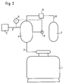
- Fig.2:
- Eine Abwandlung der Vorrichtung von Figur 1.
- Fig.1:
- A device suitable for carrying out the method.
- Fig. 2:
- A modification of the device of FIG. 1.
In Figur 1 ist der zu inertisierende Reaktor 1 durch eine Rohrleitung 2 mit einer Entnahmequelle 3 für Stickstoff als Hauptkomponente über ein Mischorgan 4 verbunden. In dem Abschnitt der Rohrleitung 2 zwischen der Entnahmequelle 3 und dem Mischorgan 4 ist ein Durchflußmesser 5 angeordnet, der über eine Steuerleitung, der kein Bezugszeichen zugeordnet ist, mit einer Dosiervorrichtung 6 verbunden ist, die von ihm angesteuert wird und die die Zufuhr eines weiteren Inertisierungsgases als Zusatzkomponente aus der Entnahmequelle 7 über die Rohrleitung 8 in das Mischorgan 4 reguliert. Das Mischorgan 4 ist über eine weitere Rohrleitung 9 mit der Entnahmequelle 7 für die Zusatzkomponente verbunden, die eine Regelvorrichtung 10 aufweist, mit der eine vollständige Versorgung des Mischorgans 4 mit der Zusatzkomponente gewährleistet werden kann. Zu diesem Zweck ist ein Drucksensor 12 vorgesehen, der mit dem Innern des Mischorgans 4 in Verbindung steht und über eine Steuerleitung an die Regelvorrichtung 10 angeschlossen ist. Eine solche Versorgung ausschließlich mit der Zusatzkomponente ist für Notfälle bei Ausfall der Hauptkomponente vorgesehen.In FIG. 1, the reactor 1 to be rendered inert is connected by a
In Figur 2, in der gleichen Vorrichtungselementen dieselben Bezugszeichen zugeordnet sind, ist die Regelvorrichtung 10 in der Rohrleitung 9 unter Wegfall der Rohrleitung 8 mit der Dosiervorrichtung 6 gegen eine Regeleinheit 11 ausgetauscht, die die Funktion der Regelvorrichtung 10 und der Dosiervorrichtung 6 in einer Einheit übernimmt. Sie wird demgemäß durch die Steuerleitung, die mit dem Durchflußmesser 5 in Verbindung steht, angesteuert. Die Regeleinheit 11 besitzt ebenfalls einen Drucksensor 12.In FIG. 2, in which the same reference numerals are assigned to the same device elements, the
Erfindungsgemäß wird nun der Reaktor 1 mit einem Inertisierungsgasgemisch vor Brand oder Explosion geschützt, das eine höhere Dichte hat als die den Reaktor 1 umgebende Luft. Hierbei geht die Erfindung davon aus, daß mit Stickstoff, welcher leichter als Luft ist, inertisiert wird. Stickstoff ist preiswert und kann leicht zur Verfügung gestellt werden. Geeignete Gase als Zusatzkomponente zur Erhöhung der Dichte des Inertisierungsgasgemisches sind beispielsweise Ar, CO₂, Xe, SF₆ und höhere Edelgase. Die Auswahl der Zusatzkomponente erfolgt selbstverständlich so, daß sie unter den gegebenen Bedingungen kein Reaktionspartner ist. Wird der Reaktor 1, der zu verarbeitende, leicht brennbare Güter enthält, geöffnet, so wird auch zu diesem Zeitpunkt eine sichere Inertisierung gewährleistet, da sich das Inertisierungsgas aufgrund seiner gegenüber der Umgebungsluft größeren Dichte schützend über die leicht brennbare Oberfläche des zu inertisierenden Produktes legt. Dies wird gewährleistet, indem dem Reaktor 1 Stickstoff über ein Mischorgan 4, das beispielsweise als Pufferbehälter ausgebildet sein kann, zugeführt wird, welchem zur Erhöhung der Inertisierungsgasdichte eine zweite Komponente aus der Entnahmequelle 7 beigemischt wird. Die Entnahmequelle 3 für den Stickstoff ist vorzugsweise eine on-site-Anlage, beispielsweise eine PSA-Anlage. Es kann aber auch ein Flüssiggastank eingesetzt werden. Zur Erhöhung der Inertisierungsgasdichte wird aus der Entnahmequelle 7, die eine zweite Komponente höherer Dichte als der des Stickstoffes, in diesem Fall Argon, enthält, zusätzlich Gas in das Mischorgan 4 eingespeist. Die Menge an zugegebenem Argon kann für wenig schwankende Verbräuche an Inertisierungsgas über eine feste Einstellung der Dosiervorrichtung 6 auf die maximale Leistung der Entnahmequelle 3 vorgegeben werden. In einer Vorrichtung dieser Art können auch mehrere Reaktoren angeschlossen sein, von denen nicht alle gleichzeitig in Betrieb sind. Bei der Zuschaltung mehrerer Reaktoren muß die Menge an zuführendem Argon nach der Spitzenbelastung eingestellt sein.According to the invention, the reactor 1 is now protected against fire or explosion with an inerting gas mixture which has a higher density than the air surrounding the reactor 1. Here, the invention assumes that inerting is carried out with nitrogen, which is lighter than air. Nitrogen is inexpensive and can be easily provided. Suitable gases as an additional component to increase the density of the inerting gas mixture are, for example, Ar, CO₂, Xe, SF₆ and higher noble gases. The selection of the additional component is of course carried out so that it is not a reaction partner under the given conditions. If the reactor 1, the easily combustible to be processed Contains goods, opened, safe inerting is also guaranteed at this point in time, because the inerting gas, due to its greater density compared to the ambient air, protects the easily combustible surface of the product to be rendered inert. This is ensured by supplying nitrogen to the reactor 1 via a mixing element 4, which can be designed, for example, as a buffer tank, to which a second component from the
Im Falle einer Unterversorgung der Reaktoren durch die Entnahmequelle 3 sinkt der Druck im Mischorgan 4. Bei der in Figur 2 dargestellten Ausführungsform wird dann über den Drucksensor 12 der Regelkreis, welcher über den Durchflußmesser 5 reguliert wird, überbrückt und der Fluß durch den Drucksensor 12 gesteuert. Alternativ kann gemäß Figur 1 die Dosiervorrichtung 6 den Fluß regulieren, indem die Zufuhr durch Steuerung aus Signalen des Durchflußmessers 5 der Menge an durchlaufendem Stickstoff angepaßt wird. Als Entnahmequelle 7 dient vorzugsweise ein Flüssig-Argontank. Aus ihm kann die Zudosierung von Argon zum Stickstoff erfolgen. Zusätzlich ist der Flüssig-Argontank über eine weitere Rohrleitung 9 mit dem Mischorgan 4 verbunden. Für den Fall, daß die Entnahmemenge aus dem Mischorgan 4 durch den Abschnitt der Rohrleitung, der das Mischorgan 4 und den Reaktor 1 verbindet, größer ist als die Entnahmequelle 7 bei maximaler Entnahmekapazität über die Dosiervorrichtung 6 liefern kann, kann durch die Entnahmequelle 7 eine weitere Inertisierung über die Rohrleitung 9, die hierfür mit einem größeren Rohrquerschnitt ausgelegt ist, gewährleistet werden. Hierzu ist in der Rohrleitung 9 eine Regelvorrichtung 11 angeordnet, die einen Druckabfall durch mangelnde Stickstoffversorgung im Mischorgan 4 registriert und darauf eine stärkere Argon-Entnahme aus der Entnahmequelle 7 einleitet. Diese Einrichtung, die für den Notfall vorgesehen ist, hat weiterhin den Vorteil, daß noch günstigere Bedingungen für die Inertisierung geschaffen werden. Die im Vergleich zum Inertisierungsgasgemisch wesentlich schwerere Komponente sinkt schnell auf das zu schützende Produkt ab und bewirkt insbesondere bei geöffnetem Reaktor einen nach wir vor sicheren Schutz.If the reactors are undersupplied by the extraction source 3, the pressure in the mixing element 4 drops. In the embodiment shown in FIG . Alternatively, according to FIG. 1, the metering device 6 can regulate the flow by switching off the supply by control Signals of the
Die Dichte des Inertisierungsgases soll im Idealfall einen Wert annehmen, der über der der Umgebungsluft und unterhalb der Dichte der Atmosphäre des Reaktorinnenraumes liegt, die beispielsweise aufgrund der Sättigung des Inertisierungsgases mit Lösungsmitteldämfen sehr hoch sein kann. Die Wahl der zuzumischenden Inertgase hängt in starkem Maße von den Medien im Behälter ab. CO₂ wird häufig aufgrund der chemischen Randbedingungen ausscheiden. Ar hingegen wird häufig das Gas der Wahl sein, da es häufig eine niedrigere Dichte als das Gemisch aus Lösungsmitteldämpfen, Inertgas und Restbestandteilen aus der Umgebungsluft, hat. Eine Durchmischung von Inertgas und schwererer Behälteratmosphäre wird somit verhindert, so daß eine saubere Überschichtung erfolgt die eine sichere Inertisierung gewährleistet. Die Dichte des Inertisierungsgases kann auch individuell auf die Dichteverhältnisse von Reaktorkopfinhalt und der Umgebungsluft eingestellt werden. Selbstverständlich kommen für die dichteregulierte Inertisierung auch andere geeignete Inertgase in Frage. Durch das erfindungsgemäße Verfahren und die Vorrichtung wird in jedem Fall ein geringerer Inertgasverbrauch gewährleistet. Dies soll an einem Beispiel wie folgt gezeigt werden:The density of the inerting gas should ideally assume a value which is above that of the ambient air and below the density of the atmosphere of the reactor interior, which can be very high, for example due to the saturation of the inerting gas with solvent vapors. The choice of the inert gases to be mixed depends to a large extent on the media in the container. CO₂ is often eliminated due to the chemical boundary conditions. Ar, on the other hand, is often the gas of choice because it often has a lower density than the mixture of solvent vapors, inert gas and residual components from the ambient air. Mixing of inert gas and heavier container atmosphere is thus prevented, so that a clean overlay takes place, which ensures safe inerting. The density of the inerting gas can also be individually adjusted to the density ratio of the reactor head content and the ambient air. Of course, other suitable inert gases are also suitable for density-regulated inerting. In any case, the inventive method and the device ensure lower inert gas consumption. This should be shown using an example as follows:
Tabelle I zeigt Wertepaare für den Stickstoffverbrauch als Ergebnis einer Inertisierung mit reinem Stickstoff für verschiedene Öffnungsdurchmesser eines Reaktores. Sie bezieht sich wie die folgende Tabelle II auf eine Inertisierung nach dem Verfahren der noch nicht veröffentlichten deutschen Patentanmeldung P 44 13 074.041.
Tabelle II zeigt die Verbrauchswerte für Stickstoff und Argon des erfindungsgemäßen Verfahrens für eine Inertisierung, bei der die gleichen Sauerstoff-Grenzwerte eingehalten wurden wie bei den Werten in Tabelle I. Die Zusammensetzung eines Inertisierungsgases für die Durchführung des erfindungsgemäßen Verfahrens war in diesem Fall: Stickstoff 90 Vol%, Argon 8 Vol%, Rest-Sauerstoff 2 Vol%.
Vergleichbare Ergebnisse werden mit einem Inertisierungsgas der Zusammensetzung Stickstoff 92 Vol%, CO₂ 6 Vol% und Rest-Sauerstoff 2 Vol% erreicht.Comparable results are achieved with an inerting gas with the composition nitrogen 92 vol%, CO₂ 6 vol% and
Die Ziele der Erfindung lassen sich in der Regel schon erreichen, wenn die Dichte des zugeführten Inertisierungsgasgemisches nur geringfügig, vorzugsweise weniger als 2 bis 5 %, über der Dichte der Umgebungsluft liegt. Die Grenze von 2 % ist durch die Möglichkeiten der Regelung bedingt. Die obere Grenze ist allein durch wirtschaftliche Überlegungen bedingt und kann auch höher sein, z.B. 15 %.The objectives of the invention can generally be achieved if the density of the inert gas mixture supplied is only slightly, preferably less than 2 to 5%, above the density of the ambient air. The limit of 2% is due to the possibilities of regulation. The upper limit is solely due to economic considerations and can also be higher, e.g. 15%.
Wie aus den Tabellen zu entnehmen ist, ist der unmittelbare Vorteil des erfindungsgemäßen Verfahrens ein deutlich reduzierter Inertisierungsgasverbrauch und somit eine erhebliche Kostenersparnis. Dies gilt auch noch dann, wenn zur Versorgung mit der Zweiten Komponente höherer Dichte ein Flüssigkeitstank anstelle einer Versorgung mit Gasflaschen eingesetzt wird. Der Flüssigkeitstank für die zweite Komponente bietet dafür die zusätzliche Sicherheit einer backup-Versorgung für den Ernstfall, bei dem die Versorgung mit der Hauptkomponente ausfällt oder ein Spitzenbedarf gedeckt werden muß. In einem solchen Ernstfall ist der Verbrauch an der schwereren Komponente geringer gegenüber der Versorgung mit einem konventionellen, leichten Inertisierungsgas, da erfindunggemäß eine bessere Abschirmung des vor Brand zu schützenden Gutes durch die höhere Dichte des schwereren Inertisierungsgases erfolgt. Dies führt zu weiteren Ersparnissen. Durch den Einsatz einer on-site-Versorgung durch die Hauptkomponente wird ein Tank und dessen regelmäßige Befüllung eingespart, so daß insgesamt ein Kostenvorteil entsteht.As can be seen from the tables, the direct advantage of the method according to the invention is a significantly reduced inerting gas consumption and thus a considerable cost saving. This also applies if a liquid tank is used instead of a supply of gas bottles for the supply with the second component of higher density. Of the The liquid tank for the second component offers the additional security of a backup supply for emergencies in which the supply of the main component fails or a peak demand has to be met. In such an emergency, the consumption of the heavier component is lower than the supply with a conventional, light inerting gas, since, according to the invention, the goods to be protected against fire are better shielded by the higher density of the heavier inerting gas. This leads to further savings. By using an on-site supply by the main component, a tank and its regular filling are saved, so that an overall cost advantage arises.
Ein weiterer Vorteil des erfindungsgemäßen Verfahrens ist die Reduktion der Gasbewegung im Kopfraum des Reaktors beziehungsweise des zu inertisierenden Systems, mit der Folge noch weiterer Minderung von Staubaustrag. Im Einzelfall wird auch eine Verringerung der gegebenenfalls notwendigen Reaktorabsaugung erreicht, mit der Folge, daß geringere Mengen am Abgas und geringere Verluste an z.B. Lösemitteln durch das Abgas entstehen.Another advantage of the method according to the invention is the reduction of the gas movement in the head space of the reactor or of the system to be rendered inert, with the result that the dust discharge is further reduced. In individual cases, a reduction in the reactor extraction that may be necessary is also achieved, with the result that smaller amounts of exhaust gas and lower losses of e.g. Solvents are created by the exhaust gas.
Claims (11)
daß neben der Hauptkomponente Stickstoff mindestens ein weiteres Inertisierungsgas als Zusatzkomponente zugeführt wird mit der Maßgabe, daß die Dichte des zugeführten Inertgasgemisches über der Dichte der Umgebungsluft liegt.Method for inerting reactors (1) containing combustible substances, which are at least temporarily open, in which nitrogen is introduced as the inerting gas into the interior of the reactor, characterized in that
that in addition to the main component nitrogen, at least one further inerting gas is supplied as an additional component, with the proviso that the density of the inert gas mixture supplied is above the density of the ambient air.
dadurch gekennzeichnet,
daß die Dichte des zugeführten Inertisierungsgasgemisches nur geringfügig, vorzugsweise weniger als 2 bis 5 %, über der Dichte der Umgebungsluft liegt.Method according to claim 1,
characterized,
that the density of the inert gas mixture supplied is only slightly, preferably less than 2 to 5%, above the density of the ambient air.
dadurch gekennzeichnet,
daß Argon und/oder Kohlendioxid als Zusatzkomponente zugeführt wird.The method of claim 1 or 2,
characterized,
that argon and / or carbon dioxide is supplied as an additional component.
dadurch gekennzeichnet,
daß die Hauptkomponente Stickstoff simultan vor Ort erzeugt wird.Method according to one of claims 1 to 3,
characterized,
that the main component nitrogen is generated simultaneously on site.
dadurch gekennzeichnet,
daß zwischen dem Reaktor (1) und der Entnahmequelle (3) für Stickstoff ein Mischorgan (4) angeordnet ist, das mit mindestens einer weiteren Entnahmequelle (7) für ein zusätzliches Inertisierungsgas durch mindestens eine Rohrleitung (8, 9) in Verbindung steht.Device for carrying out the process according to claims 1 to 4, with at least one reactor (1), a removal source (3) for nitrogen and a pipeline (2) which supplies the nitrogen to the reactor (1),
characterized,
that a mixing element (4) is arranged between the reactor (1) and the removal source (3) for nitrogen, which is connected to at least one further removal source (7) for an additional inerting gas through at least one pipeline (8, 9).
dadurch gekennzeichnet,
daß das Mischorgan (4) als Pufferbehälter ausgebildet ist.Device according to claim 5,
characterized,
that the mixing element (4) is designed as a buffer container.
dadurch gekennzeichnet,
daß eine der das Mischorgan (4) mit der Entnahmequelle (7) verbindenden Rohrleitungen (9) mit einer Regelvorrichtung (10) ausgestattet ist, die bei Abfall des Druckes des Mischorgans (4) mittels eines Drucksensors (12) auf den Betrieb aus der Entnahmequelle (7) umstellt.Apparatus according to claim 5 or 6,
characterized,
that one of the mixing element (4) with the extraction source (7) connecting pipes (9) is equipped with a control device (10) which, when the pressure of the mixing element (4) drops by means of a pressure sensor (12), for operation from the extraction source (7).
dadurch gekennzeichnet,
daß zwischen der Entnahmequelle (3) für Stickstoff und dem Mischorgan (4) ein Durchflußmesser (5) angeordnet ist, der über eine Steuerleitung mit einer Dosiereinrichtung (6) in Verbindung steht, die in einer der das Mischorgan (4) mit der Entnahmequelle (7) verbindenden Rohrleitung (8) angeordnet ist.Device according to one of claims 5 to 7,
characterized,
that between the extraction source (3) for nitrogen and the mixing element (4) a flow meter (5) is arranged, which is connected via a control line to a metering device (6) which in one of the mixing elements (4) with the extraction source ( 7) connecting pipe (8) is arranged.
dadurch gekennzeichnet,
daß die Rohrleitung (9) mit einer Regeleinheit (11) ausgestattet ist, die einerseits über eine Steuerleitung mit dem Durchflußmesser (5) als Signalgeber in Verbindung steht und die andererseits über einen mit dem Mischorgan (4) in Verbindung stehenden Drucksensor (12) verfügt, um bei Abfall des Druckes im Innern des Mischorgans (4) auf Versorgung aus der Entnahmequelle (7) umstellen zu können.Apparatus according to claim 5 or 6, in which only one pipe (9) connecting the mixing element (4) to the extraction source (7) for the additional inerting gas is provided and a flow meter (5) is provided in the pipe (2),
characterized,
that the pipe (9) is equipped with a control unit (11), which is connected on the one hand via a control line to the flow meter (5) as a signal transmitter and on the other hand has a pressure sensor (12) connected to the mixing element (4) to be able to switch to supply from the extraction source (7) when the pressure inside the mixing element (4) drops.
dadurch gekennzeichnet,
daß die Entnahmequelle (3) für Stickstoff eine on-site-Anlage ist.Device according to one of claims 5 to 9,
characterized,
that the source (3) for nitrogen is an on-site system.
dadurch gekennzeichnet,
daß die Entnahmequelle (3) für Stickstoff ein Flüssigkeitstank ist.Device according to one of claims 5 to 9,
characterized,
that the extraction source (3) for nitrogen is a liquid tank.
Applications Claiming Priority (2)
| Application Number | Priority Date | Filing Date | Title |
|---|---|---|---|
| DE4432344A DE4432344C2 (en) | 1994-09-12 | 1994-09-12 | Method and device for inerting reactors |
| DE4432344 | 1994-09-12 |
Publications (2)
| Publication Number | Publication Date |
|---|---|
| EP0700715A2 true EP0700715A2 (en) | 1996-03-13 |
| EP0700715A3 EP0700715A3 (en) | 1996-04-17 |
Family
ID=6527955
Family Applications (1)
| Application Number | Title | Priority Date | Filing Date |
|---|---|---|---|
| EP95112123A Ceased EP0700715A2 (en) | 1994-09-12 | 1995-08-02 | Process and device for rendering reactors inert |
Country Status (4)
| Country | Link |
|---|---|
| US (1) | US5837192A (en) |
| EP (1) | EP0700715A2 (en) |
| DE (1) | DE4432344C2 (en) |
| ZA (1) | ZA956283B (en) |
Families Citing this family (4)
| Publication number | Priority date | Publication date | Assignee | Title |
|---|---|---|---|---|
| US6306350B1 (en) * | 1999-05-19 | 2001-10-23 | Itt Manufacturing Enterprises, Inc. | Water sampling method and apparatus with analyte integration |
| US20040046670A1 (en) * | 2002-09-05 | 2004-03-11 | Adams Paul R. | Gas blanket management system and method |
| EP3912688A1 (en) * | 2020-05-19 | 2021-11-24 | L'air Liquide, Société Anonyme Pour L'Étude Et L'exploitation Des Procédés Georges Claude | Secure inerting device |
| CN113682666A (en) * | 2021-08-27 | 2021-11-23 | 江苏龚匠文物保护研究有限公司 | Atmospheric-pressure low-oxygen nitrogen-filled cultural relic protection airtight space |
Citations (1)
| Publication number | Priority date | Publication date | Assignee | Title |
|---|---|---|---|---|
| DE3914783A1 (en) | 1989-05-05 | 1990-11-08 | Messer Griesheim Gmbh | DEVICE FOR PREVENTING THE INTRACTION OF FOREIGN GASES BY THE FEEDING OPENING OF AN INERTIZED REACTION CONTAINER |
Family Cites Families (11)
| Publication number | Priority date | Publication date | Assignee | Title |
|---|---|---|---|---|
| DE1508423B2 (en) * | 1966-07-04 | 1970-08-06 | Messer Griesheim GmbH, 6OOO Frankfurt | Process for the production of protective gas for metallurgical purposes |
| US3899099A (en) * | 1973-06-21 | 1975-08-12 | Tank Sapp Uk Ltd | Inert gas system and method for tankers |
| DE2744767A1 (en) * | 1977-10-05 | 1979-04-12 | Ziemann Gmbh A | Inert rendering system for storage vessel - feeds in nitrogen quantity equivalent to gases removed by reactor |
| FR2410504A1 (en) * | 1977-12-05 | 1979-06-29 | Air Liquide | Safety control in chemical reactor carrying out oxidations - comprises oxygen concn. monitoring in gaseous phase and nitrogen injections if set concn. is reached |
| GB2026859A (en) * | 1978-04-07 | 1980-02-13 | Boc Ltd | Method and apparatus for storing a volatile liquid |
| US4213935A (en) * | 1978-06-19 | 1980-07-22 | John Zink Company | Apparatus for use in conjunction with boiler flue gases for generating inert blanketing gases |
| US4261950A (en) * | 1979-02-06 | 1981-04-14 | American Sterilizer Company | Sterilizing apparatus and integrated sterilizer control |
| FR2455239A1 (en) * | 1979-04-25 | 1980-11-21 | Charbonnages Ste Chimique | PROCESS FOR REDUCING THE RISK OF INFLAMMATION AND EXPLOSION RESULTING FROM THE DECOMPOSITION OF ETHYLENE UNDER HIGH PRESSURE AND DEVICE FOR CARRYING OUT SAID METHOD |
| DE4029088C1 (en) * | 1990-09-13 | 1992-02-13 | Fresenius Ag, 6380 Bad Homburg, De | |
| JP2595159B2 (en) * | 1991-12-16 | 1997-03-26 | 帝人化成株式会社 | Equipment for fumigation |
| WO1993016808A1 (en) * | 1992-02-24 | 1993-09-02 | Richter Gedeon Vegyészeti Gyár Rt. | Method of and apparatus for making inerted closed spaces |
-
1994
- 1994-09-12 DE DE4432344A patent/DE4432344C2/en not_active Expired - Fee Related
-
1995
- 1995-07-27 ZA ZA956283A patent/ZA956283B/en unknown
- 1995-08-02 EP EP95112123A patent/EP0700715A2/en not_active Ceased
- 1995-09-01 US US08/522,633 patent/US5837192A/en not_active Expired - Fee Related
Patent Citations (1)
| Publication number | Priority date | Publication date | Assignee | Title |
|---|---|---|---|---|
| DE3914783A1 (en) | 1989-05-05 | 1990-11-08 | Messer Griesheim Gmbh | DEVICE FOR PREVENTING THE INTRACTION OF FOREIGN GASES BY THE FEEDING OPENING OF AN INERTIZED REACTION CONTAINER |
Also Published As
| Publication number | Publication date |
|---|---|
| US5837192A (en) | 1998-11-17 |
| EP0700715A3 (en) | 1996-04-17 |
| DE4432344C2 (en) | 1998-11-05 |
| DE4432344A1 (en) | 1996-05-15 |
| ZA956283B (en) | 1996-03-13 |
Similar Documents
| Publication | Publication Date | Title |
|---|---|---|
| EP0120271B1 (en) | Process and apparatus for making inert a transport container | |
| EP1062005B1 (en) | Inerting method for preventing and extinguishing fires in enclosed spaces | |
| DE2855174A1 (en) | METHOD AND DEVICE FOR RETURNING THE CARRIER GAS IN GAS CHROMATOGRAPHIC SYSTEMS | |
| DE60021766T2 (en) | METHOD AND DEVICE FOR PROVIDING A GAS MIXTURE | |
| EP0700715A2 (en) | Process and device for rendering reactors inert | |
| EP3614475A1 (en) | Method for treating hydrogen and oxygen-containing residual gases of fuel cells and residual gas treatment system | |
| EP0019907B1 (en) | Process and apparatus for the recombination of hydrogen contained in the security chamber of a nuclear reactor | |
| DE102005023101A1 (en) | Inert gas e.g. nitrogen, introducing method for fire-extinguishing system, involves conducting compressed inert gas with defined flow-rate into fire-extinguishing or protection area to maintain intended room pressure | |
| DE19949154A1 (en) | Water treatment apparatus for raising oxygen solubility in high purity drinking water comprises high-pressure pump, closed container, ozone injector, cooler, and supersonic vibrator | |
| DE4020890C2 (en) | ||
| DE19535554A1 (en) | Procedure for crushing of containers used to hold reactive or dangerous substances | |
| DE4445656C1 (en) | Storage of acetylene | |
| EP0681866B1 (en) | Process for rendering reactors inert | |
| DE3034622A1 (en) | Foam generating and conveying equipment - uses foam agent-water mixture with introduction of compressed air | |
| DE2603798B1 (en) | DEVICE FOR FASTENING LIQUIDS AND / OR LIQUID-SOLID MIXTURES | |
| DE3843436C2 (en) | ||
| EP1043045B1 (en) | Fire extinguishing plant | |
| WO2002084167A1 (en) | Dimensionally unstable storage container and method for storing gases | |
| EP3626327B1 (en) | Inertisation method and inertisation system, in particular for preventing fires, and use of an inertisation system | |
| DE3413861A1 (en) | Adsorber and adsorption process using the adsorber | |
| DE1910405C3 (en) | Method and device for the production of protective gas mixtures for welding and cutting | |
| DE19722111A1 (en) | Installation for the simulation of subterranean environments | |
| DE3718132A1 (en) | GAS ENTRY DEVICE FOR SOLID PROTECTION | |
| EP1859887B1 (en) | Device and method for wave soldering | |
| DE2755881B2 (en) | Process for separating fission and activation products from a gas atmosphere and device for carrying out the process |
Legal Events
| Date | Code | Title | Description |
|---|---|---|---|
| PUAI | Public reference made under article 153(3) epc to a published international application that has entered the european phase |
Free format text: ORIGINAL CODE: 0009012 |
|
| PUAL | Search report despatched |
Free format text: ORIGINAL CODE: 0009013 |
|
| AK | Designated contracting states |
Kind code of ref document: A2 Designated state(s): DE ES FR GB NL |
|
| AK | Designated contracting states |
Kind code of ref document: A3 Designated state(s): DE ES FR GB NL |
|
| 17P | Request for examination filed |
Effective date: 19961017 |
|
| GRAG | Despatch of communication of intention to grant |
Free format text: ORIGINAL CODE: EPIDOS AGRA |
|
| 17Q | First examination report despatched |
Effective date: 19990322 |
|
| STAA | Information on the status of an ep patent application or granted ep patent |
Free format text: STATUS: THE APPLICATION HAS BEEN REFUSED |
|
| 18R | Application refused |
Effective date: 19990912 |