EP0700664B1 - Articulation for components of an external fixator - Google Patents
Articulation for components of an external fixator Download PDFInfo
- Publication number
- EP0700664B1 EP0700664B1 EP95810535A EP95810535A EP0700664B1 EP 0700664 B1 EP0700664 B1 EP 0700664B1 EP 95810535 A EP95810535 A EP 95810535A EP 95810535 A EP95810535 A EP 95810535A EP 0700664 B1 EP0700664 B1 EP 0700664B1
- Authority
- EP
- European Patent Office
- Prior art keywords
- jaws
- articulation
- bars
- grooves
- pairs
- Prior art date
- Legal status (The legal status is an assumption and is not a legal conclusion. Google has not performed a legal analysis and makes no representation as to the accuracy of the status listed.)
- Expired - Lifetime
Links
- 210000000988 bone and bone Anatomy 0.000 description 14
- 230000000903 blocking effect Effects 0.000 description 6
- 239000012634 fragment Substances 0.000 description 5
- 239000000834 fixative Substances 0.000 description 2
- 239000000463 material Substances 0.000 description 2
- 229910000831 Steel Inorganic materials 0.000 description 1
- XAGFODPZIPBFFR-UHFFFAOYSA-N aluminium Chemical compound [Al] XAGFODPZIPBFFR-UHFFFAOYSA-N 0.000 description 1
- 229910052782 aluminium Inorganic materials 0.000 description 1
- 210000001367 artery Anatomy 0.000 description 1
- 230000015556 catabolic process Effects 0.000 description 1
- 230000000295 complement effect Effects 0.000 description 1
- 239000002131 composite material Substances 0.000 description 1
- 230000006835 compression Effects 0.000 description 1
- 238000007906 compression Methods 0.000 description 1
- 238000007596 consolidation process Methods 0.000 description 1
- 210000003275 diaphysis Anatomy 0.000 description 1
- 230000000694 effects Effects 0.000 description 1
- 210000002745 epiphysis Anatomy 0.000 description 1
- 238000003780 insertion Methods 0.000 description 1
- 230000037431 insertion Effects 0.000 description 1
- 229910001234 light alloy Inorganic materials 0.000 description 1
- 210000005036 nerve Anatomy 0.000 description 1
- 230000000399 orthopedic effect Effects 0.000 description 1
- 230000002787 reinforcement Effects 0.000 description 1
- 230000000717 retained effect Effects 0.000 description 1
- 238000010079 rubber tapping Methods 0.000 description 1
- 239000010959 steel Substances 0.000 description 1
- 210000001519 tissue Anatomy 0.000 description 1
Images

Classifications
-
- A—HUMAN NECESSITIES
- A61—MEDICAL OR VETERINARY SCIENCE; HYGIENE
- A61B—DIAGNOSIS; SURGERY; IDENTIFICATION
- A61B17/00—Surgical instruments, devices or methods, e.g. tourniquets
- A61B17/56—Surgical instruments or methods for treatment of bones or joints; Devices specially adapted therefor
- A61B17/58—Surgical instruments or methods for treatment of bones or joints; Devices specially adapted therefor for osteosynthesis, e.g. bone plates, screws, setting implements or the like
- A61B17/60—Surgical instruments or methods for treatment of bones or joints; Devices specially adapted therefor for osteosynthesis, e.g. bone plates, screws, setting implements or the like for external osteosynthesis, e.g. distractors, contractors
-
- F—MECHANICAL ENGINEERING; LIGHTING; HEATING; WEAPONS; BLASTING
- F16—ENGINEERING ELEMENTS AND UNITS; GENERAL MEASURES FOR PRODUCING AND MAINTAINING EFFECTIVE FUNCTIONING OF MACHINES OR INSTALLATIONS; THERMAL INSULATION IN GENERAL
- F16B—DEVICES FOR FASTENING OR SECURING CONSTRUCTIONAL ELEMENTS OR MACHINE PARTS TOGETHER, e.g. NAILS, BOLTS, CIRCLIPS, CLAMPS, CLIPS OR WEDGES; JOINTS OR JOINTING
- F16B7/00—Connections of rods or tubes, e.g. of non-circular section, mutually, including resilient connections
- F16B7/04—Clamping or clipping connections
- F16B7/044—Clamping or clipping connections for rods or tubes being in angled relationship
- F16B7/048—Clamping or clipping connections for rods or tubes being in angled relationship for rods or for tubes without using the innerside thereof
- F16B7/0493—Clamping or clipping connections for rods or tubes being in angled relationship for rods or for tubes without using the innerside thereof forming a crossed-over connection
-
- A—HUMAN NECESSITIES
- A61—MEDICAL OR VETERINARY SCIENCE; HYGIENE
- A61B—DIAGNOSIS; SURGERY; IDENTIFICATION
- A61B17/00—Surgical instruments, devices or methods, e.g. tourniquets
- A61B17/56—Surgical instruments or methods for treatment of bones or joints; Devices specially adapted therefor
- A61B17/58—Surgical instruments or methods for treatment of bones or joints; Devices specially adapted therefor for osteosynthesis, e.g. bone plates, screws, setting implements or the like
- A61B17/60—Surgical instruments or methods for treatment of bones or joints; Devices specially adapted therefor for osteosynthesis, e.g. bone plates, screws, setting implements or the like for external osteosynthesis, e.g. distractors, contractors
- A61B17/64—Devices extending alongside the bones to be positioned
- A61B17/645—Devices extending alongside the bones to be positioned comprising a framework
-
- A—HUMAN NECESSITIES
- A61—MEDICAL OR VETERINARY SCIENCE; HYGIENE
- A61B—DIAGNOSIS; SURGERY; IDENTIFICATION
- A61B17/00—Surgical instruments, devices or methods, e.g. tourniquets
- A61B17/56—Surgical instruments or methods for treatment of bones or joints; Devices specially adapted therefor
- A61B17/58—Surgical instruments or methods for treatment of bones or joints; Devices specially adapted therefor for osteosynthesis, e.g. bone plates, screws, setting implements or the like
- A61B17/60—Surgical instruments or methods for treatment of bones or joints; Devices specially adapted therefor for osteosynthesis, e.g. bone plates, screws, setting implements or the like for external osteosynthesis, e.g. distractors, contractors
- A61B17/64—Devices extending alongside the bones to be positioned
- A61B17/6466—Devices extending alongside the bones to be positioned with pin-clamps movable along a solid connecting rod
Definitions
- the present invention is in the field of orthopedics and relates more particularly to a joint for positioning and fixing components cylindrical - fixation bars or bone plugs - an external fixator.
- fixators components whose components are put in place after the plugs have been inserted in the optimal position relative to the bone fragment to be maintained and to the tissue surrounding him.
- the fixing bars constituting the frame of the fixative are then placed between the plugs and joints provide the connection between the bars and the plugs or between stiffening bars. It is obviously necessary that these joints allow hold bars or plugs at an angle variable.
- European patent EP-0.321.472 (WO-88/01152) describes an articulation for the relative positioning of fixation bars or bone plugs of a fixer external.
- This joint comprises several pairs of jaws having grooves on their adjacent faces which form a passage intended to receive a bar or a plug, means for blocking the angular position between said pairs and clamping means crossing said pairs of jaws to clamp the bars or plugs in a relative position.
- the jaws forming a pair are provided respectively a positioning projection and a clearance complementary form.
- the present invention aims to overcome these drawbacks and relates to a hinge for positioning relative of fixing bars or plugs of a external fixator, articulation comprising several pairs jaws having on their adjacent faces grooves which form a passage intended to receive a bar or plug, position locking means angular between said pairs and clamping means crossing said pairs of jaws to clamp the bars or plugs retained between the jaws in a relative position.
- elastic means are interposed between said pairs of jaws and in that the grooves forming said passage are positioned and arranged so as to have an opening exterior allowing the bar or plug to be clipped by pressure from the latter, from the opening of the jaw in said passage, against the elastic means which press the adjacent faces of the jaws against each other the other to maintain the joint on the bars or plugs before blocking the joint.
- the means of clamping consist of a shaft which cooperates with a stopper to maintain stacking of jaws around the clamping shaft, when loosening this one.
- the invention also extends to a fixer external with at least one bone plug inserted on either side of the divide, a frame composed of fixing bars, and at least one articulation arranged between a plug and a bar or between two bars to their relative positioning. It is characterized in that that said articulation has at least two openings external allowing the clipping of bars or plugs by pressure of these in passages provided for in this effect, against elastic means that hold the bars or plugs between the jaws constituting the joint before blocking it.
- This fixer has the advantage of space reduced.
- one or more bars can be removed during bone consolidation.
- the joint shown in Figure 1 is composed by stacking two pairs of jaws made up respectively by an upper jaw 10 and an upper intermediate jaw 20, as well as by a lower intermediate jaw 30 and a jaw lower 40. These four jaws are mounted on a clamping shaft 50, which permanently maintains the jaws together thanks to the stopper 60.
- elastic means 70 are arranged between the jaws intermediaries 20 and 30 and tend to discard them.
- a fixing bar 80 and a bone plug 90 seen in section and arranged parallel on either side of the tree 50 in the example shown.
- the joint is shown in its tightening position bars or cards.
- the lower jaws 30 and 40 move under the action of elastic means up to the position bass represented in dashed lines in the drawing.
- the upper jaw 10 has an opening central 11, for the passage of the clamping shaft. Sure its face adjacent to the intermediate jaw it comprises on the one hand a groove 12 of shape corresponding to the part to be clamped, and on the other hand a positioning clearance 13. On its opposite side, the upper jaw 10 presents a spherical recess 14 intended to receive a spherical washer 15 disposed around the head of the clamping shaft 50.
- the upper intermediate jaw 20 has a central opening 21. On its face adjacent to the upper jaw, it has a passage 22 for the part to be clamped and an axial projection 23 of corresponding shape at positioning clearance 13. On its face opposite, the jaw 20 has a recess 24 for the elastic means 70 at the center of the contact surface 26 with the other intermediate jaw.
- the lower intermediate jaw 30 comprises, symmetrically, a central opening 31, a groove 32, an axial projection 33, a central recess 34 and a contact surface 36, clearly visible at the Figure 3.
- the contact surface 36 can be constituted by a toothed crown intended for reinforce the angular blocking of the two intermediate jaws. This teeth are relatively fine to allow to block the intermediate jaws in a large number of relative positions.
- the contact surface 26 is constituted by teeth radial, the bottom 26A of which is inclined a few degrees with respect to the horizontal while the edge 26B is tilted in the opposite direction, so as to ensure better grip between the intermediate jaws.
- the lower jaw 40 is distinguished from those described so far in that the central opening 41 is tapped so as to receive the clamping means 50.
- This lower jaw behaves like the upper jaw 10 already described a groove 42 for the bar position, a clearance 43 cooperating with the projection 33 and a central recess 44, for the stop piece 60.
- the superimposed jaws constitute a tubular stack.
- the jaws have a shape of circular section 18, 28, 38 and 48 on the side comprising positioning projections and clearances of corresponding shape, while they have a shape of square section 19, 29, 39 and 49 on their part provided with bar receiving grooves, in order to increase their surface in contact with the part to be positioned.
- the clamping shaft 50 has at one end gripping means external to the jaws which it crosspiece, constituted in the example given by a head square 51 flared at its base to form a circular shoulder 52 intended to cooperate with the washer 15.
- a the other end, the shaft has a thread 53 and a threaded opening 54.
- the thread 53 is intended to cooperate with threaded opening 41 of the lower jaw or with the helical sleeve 45.
- the opening threaded 54 receives the stopper 60.
- the stopper 60 has a threaded rod 61 and a closing flange 62 whose edge 63 includes a groove for housing an O-ring 64 seal. As visible in Figure 2, the flange 62 has two holes 65 intended to receive a tightening key when the shaft 50 is screwed into the stopper 60. Preferably, these two pieces will be glued.
- the stopper 60 serves to maintain the stacking of the jaws around the shaft of tightening 50 to prevent it from coming off of the lower jaw.
- the elastic means 70 which tend to spread the intermediate jaws 20 and 30 are more precisely constituted by a helical compression spring 70, the ends of which rest at the bottom of the recesses 24 and 34.
- Figure 1 shows the position of the elements of the joint when they are tight on the cylindrical parts 80 and 90, the spring 70 being compressed between the intermediate jaws 20 and 30 while Figure 3 shows a turn 71 of the spring 70.
- this spring 70 tends to separate the pairs of jaws 10.20 and 30.40, the flange 62 abuts at the bottom of the central recess 44.
- the height projections 23 and 33 is greater than the empty space between the flange 62 and the bottom of the central recess 44, for ensure the positioning of the pairs of jaws when the joint is in the open position.
- a fixing bar 80 and a bone plug 90 arranged in parallel on either side of the shaft 50, but in practice these are mounted in n no matter what angular relationship.
- the fixing bar 80 has a larger diameter than that of the bone plug 90.
- the lower jaws 30 and 40 include grooves 32, 42 round, the radius of which corresponds to that of the fixing bar 80.
- the upper jaws 10 and 20 respectively have a groove 12 profiled in V and a passage 22 intended to facilitate the lateral insertion of the bone plug. It is also possible to use upper jaws each having a round groove when the joint joins two fixing bars, as will be seen below.
- the great advantage of the joint described here is to be able to be in all time arranged on cards or bars that can be engaged by lateral clipping, the intermediate jaws moving freely against the spring 70.
- This spring is powerful enough to hold sheets or bars in place, being reduced and before the practitioner tightens the shaft 50, which allows in a single operation to block the cards or bars as well as the angular position of the jaws intermediaries.
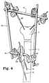
- files 91 and 92 are inserted in the diaphysis 1 of a fractured bone around the epiphysis 2 which receives sheets 93 and 94. Two sheets are shown in each bone fragment, but it is of course possible insert more.
- a first fixing bar 81 constitutes the upper part of the fixator frame, including bars 82 and 83 constitute the sides. Sheets 91 and 92 are held in a vice 100 from which the jaws receive two bars 84 and 85 which constitute the lower part of the frame of the external fixator.
- bent bars such as bar 85 which has at the exit of the vice 100 an angle of approximately 135 ° or any other value between approximately 110 ° and 160 °.
- This mounting has the advantage of avoiding rotation of the bar in the connecting piece when torques are applied to the whole by improving the breakdown of strengths.
- the fixator also as close as possible to the fractured limb to decrease the overall size.
Landscapes
- Health & Medical Sciences (AREA)
- Orthopedic Medicine & Surgery (AREA)
- Surgery (AREA)
- Life Sciences & Earth Sciences (AREA)
- Engineering & Computer Science (AREA)
- Animal Behavior & Ethology (AREA)
- Nuclear Medicine, Radiotherapy & Molecular Imaging (AREA)
- Biomedical Technology (AREA)
- Heart & Thoracic Surgery (AREA)
- Medical Informatics (AREA)
- Molecular Biology (AREA)
- General Health & Medical Sciences (AREA)
- Public Health (AREA)
- Veterinary Medicine (AREA)
- General Engineering & Computer Science (AREA)
- Mechanical Engineering (AREA)
- Surgical Instruments (AREA)
- Flanged Joints, Insulating Joints, And Other Joints (AREA)
- Non-Disconnectible Joints And Screw-Threaded Joints (AREA)
- Professional, Industrial, Or Sporting Protective Garments (AREA)
- Supports For Pipes And Cables (AREA)
- Branch Pipes, Bends, And The Like (AREA)
- Cable Accessories (AREA)
- Pharmaceuticals Containing Other Organic And Inorganic Compounds (AREA)
- Snaps, Bayonet Connections, Set Pins, And Snap Rings (AREA)
- Mutual Connection Of Rods And Tubes (AREA)
- Reinforcement Elements For Buildings (AREA)
Abstract
Description
La présente invention est du domaine de l'orthopédie et concerne plus particulièrement une articulation pour le positionnement et la fixation des composants cylindriques - barres de fixation ou fiches osseuses - d'un fixateur externe.The present invention is in the field of orthopedics and relates more particularly to a joint for positioning and fixing components cylindrical - fixation bars or bone plugs - an external fixator.
De nombreux fixateurs externes connus comportent des arceaux ou cadres ayant une forme spécifique, en fonction de laquelle les fiches osseuses sont insérées dans les fragments d'os que l'on désire maintenir. On a constaté que l'on est souvent amené ainsi à insérer les fiches relativement près de nerfs ou d'artères, ce qui peut entraíner des complications.Many known external fixers have hoops or frames with a specific shape, depending from which the bone plugs are inserted into the bone fragments that you want to maintain. We observed that we are often led to insert the cards relatively close to nerves or arteries, which can cause complications.
Pour cette raison, on a développé des fixateurs externes dont les composants sont mis en place après que les fiches aient été insérées dans la position optimale par rapport au fragment osseux à maintenir et au tissu l'entourant. Les barres de fixation constituant le cadre du fixateur sont alors mises en place entre les fiches et des articulations assurent la liaison entre les barres et les fiches ou entre des barres de rigidification. Il est évidemment nécessaire que ces articulations permettent de maintenir les barres ou fiches selon une angulation variable.For this reason, we have developed fixators components whose components are put in place after the plugs have been inserted in the optimal position relative to the bone fragment to be maintained and to the tissue surrounding him. The fixing bars constituting the frame of the fixative are then placed between the plugs and joints provide the connection between the bars and the plugs or between stiffening bars. It is obviously necessary that these joints allow hold bars or plugs at an angle variable.
Le brevet européen EP-0.321.472 (WO-88/01152) décrit une articulation pour le positionnement relatif de barres de fixation ou de fiches osseuses d'un fixateur externe. Cette articulation comporte plusieurs paires de mâchoires présentant sur leurs faces adjacentes des rainures qui forment un passage destiné à recevoir une barre ou une fiche, des moyens de blocage de la position angulaire entre lesdites paires et des moyens de serrage traversant lesdites paires de mâchoires pour serrer les barres ou fiches dans une position relative. En outre les mâchoires formant une paire sont munies respectivement d'une saillie de positionnement et d'un dégagement de forme complémentaire.European patent EP-0.321.472 (WO-88/01152) describes an articulation for the relative positioning of fixation bars or bone plugs of a fixer external. This joint comprises several pairs of jaws having grooves on their adjacent faces which form a passage intended to receive a bar or a plug, means for blocking the angular position between said pairs and clamping means crossing said pairs of jaws to clamp the bars or plugs in a relative position. In addition the jaws forming a pair are provided respectively a positioning projection and a clearance complementary form.
L'inconvénient d'un tel dispositif est qu'il doit être monté à l'avance sur les barres de fixation ou les fiches, qui sont introduites par leur extrémité. En variante on peut démonter ce type d'articulation avant de l'utiliser et de la remonter, en prenant garde de disposer les saillies et dégagements de positionnement vis-à-vis. En outre tant que ce dispositif n'est pas bloqué dans la position définitive voulue, les composants ne sont pas maintenus et peuvent bouger les uns par rapport aux autres et surtout l'articulation peut bouger par rapport aux barres de fixation et aux fiches sur lesquelles elle est montée de sorte que l'on est obligé de la maintenir en place avant de la serrer.The disadvantage of such a device is that it must be mounted in advance on the fixing bars or the plugs, which are inserted at their ends. In variant we can dismantle this type of joint before use it and reassemble, taking care to dispose of the projections and clearances of positioning opposite. Furthermore, as long as this device is not blocked in the desired final position, components are not maintained and can move relative to each other and especially the joint can move in relation to fixing bars and the plugs on which it is climb so that we have to keep it in place before tightening.
La présente invention vise à pallier ces inconvénients et a pour objet une articulation pour le positionnement relatif de barres de fixation ou de fiches d'un fixateur externe, articulation comportant plusieurs paires de mâchoires présentant sur leurs faces adjacentes des rainures qui forment un passage destiné à recevoir une barre ou une fiche, des moyens de blocage de la position angulaire entre lesdites paires et des moyens de serrage traversant lesdites paires de mâchoires pour serrer les barres ou fiches retenues entre les mâchoires dans une position relative.The present invention aims to overcome these drawbacks and relates to a hinge for positioning relative of fixing bars or plugs of a external fixator, articulation comprising several pairs jaws having on their adjacent faces grooves which form a passage intended to receive a bar or plug, position locking means angular between said pairs and clamping means crossing said pairs of jaws to clamp the bars or plugs retained between the jaws in a relative position.
Elle est caractérisée en ce que des moyens élastiques sont intercalés entre lesdites paires de mâchoires et en ce que les rainures formant ledit passage sont positionnées et agencées de manière à présenter une ouverture extérieure permettant le clipsage de la barre ou fiche par pression de cette dernière, de l'ouverture de la mâchoire dans ledit passage, à l'encontre des moyens élastiques qui pressent les faces adjacentes des mâchoires l'une contre l'autre pour maintenir l'articulation sur les barres ou fiches avant le blocage de l'articulation.It is characterized in that elastic means are interposed between said pairs of jaws and in that the grooves forming said passage are positioned and arranged so as to have an opening exterior allowing the bar or plug to be clipped by pressure from the latter, from the opening of the jaw in said passage, against the elastic means which press the adjacent faces of the jaws against each other the other to maintain the joint on the bars or plugs before blocking the joint.
Dans une variante préférentielle, les moyens de serrage sont constitués par un arbre qui coopère avec une pièce d'arrêt pour maintenir l'empilage des mâchoires autour de l'arbre de serrage, lorsque l'on desserre celui-ci.In a preferred variant, the means of clamping consist of a shaft which cooperates with a stopper to maintain stacking of jaws around the clamping shaft, when loosening this one.
L'invention s'étend également à un fixateur externe comportant au moins des fiches osseuses insérées de part et d'autre de la fracture, un cadre composé de barres de fixation, et au moins une articulation disposée entre une fiche et une barre ou entre deux barres pour leur positionnement relatif. Il est caractérisé en ce que ladite articulation comporte au moins deux ouvertures extérieures permettant le clipsage de barres ou fiches par pression de celles-ci dans des passages prévus à cet effet, à l'encontre de moyens élastiques qui maintiennent les barres ou fiches entre les mâchoires constituant l'articulation avant le blocage de celle-ci. The invention also extends to a fixer external with at least one bone plug inserted on either side of the divide, a frame composed of fixing bars, and at least one articulation arranged between a plug and a bar or between two bars to their relative positioning. It is characterized in that that said articulation has at least two openings external allowing the clipping of bars or plugs by pressure of these in passages provided for in this effect, against elastic means that hold the bars or plugs between the jaws constituting the joint before blocking it.
Ce fixateur présente l'avantage d'un encombrement réduit. En outre une ou plusieurs barres peuvent être enlevées au cours de la consolidation osseuse.This fixer has the advantage of space reduced. In addition one or more bars can be removed during bone consolidation.
Le dessin annexé représente, à titre d'exemple
non limitatif, une forme d'exécution de l'objet de la
présente invention.
L'articulation représentée à la figure 1 est
composée par l'empilage de deux paires de mâchoires constituées
respectivement par une mâchoire supérieure 10 et
une mâchoire intermédiaire supérieure 20, ainsi que par
une mâchoire intermédiaire inférieure 30 et une mâchoire
inférieure 40. Ces quatre mâchoires sont montées sur un
arbre de serrage 50, qui maintient en permanence les
mâchoires ensemble grâce à la pièce d'arrêt 60. Des
moyens élastiques 70 sont disposés entre les mâchoires
intermédiaires 20 et 30 et tendent à les écarter. On a
dessiné en traitillés à la figure 1 une barre de fixation
80 et une fiche osseuse 90, vues en coupe et disposées
parallèlement de part et d'autre de l'arbre 50 dans
l'exemple représenté.The joint shown in Figure 1 is
composed by stacking two pairs of jaws made up
respectively by an
Dans la variante représentée à la figure 1,
l'articulation est représentée dans sa position de serrage
des barres ou fiches. Lorsque l'on desserre l'arbre de
serrage 50, les mâchoires inférieures 30 et 40 se déplacent
sous l'action des moyens élastiques jusqu'à la position
basse représentée en traitillés au dessin.In the variant shown in Figure 1,
the joint is shown in its tightening position
bars or cards. When we loosen the tree
clamping 50, the
La mâchoire supérieure 10 comporte une ouverture
centrale 11, pour le passage de l'arbre de serrage. Sur
sa face adjacente à la mâchoire intermédiaire elle comporte
d'une part une rainure 12 de forme correspondant à
la pièce à serrer, et d'autre part un dégagement de positionnement
13. Sur sa face opposée, la mâchoire supérieure
10 présente une creusure 14 sphérique destinée à recevoir
une rondelle sphérique 15 disposée autour de la tête de
l'arbre de serrage 50.The
La mâchoire intermédiaire supérieure 20 présente
une ouverture centrale 21. Sur sa face adjacente à la
mâchoire supérieure, elle comporte un passage 22 pour la
pièce à serrer et une saillie axiale 23 de forme correspondant
au dégagement de positionnement 13. Sur sa face
opposée, la mâchoire 20 comporte un évidement 24 pour les
moyens élastiques 70 au centre de la surface 26 de contact
avec l'autre mâchoire intermédiaire.The upper
La mâchoire intermédiaire inférieure 30 comporte,
de manière symétrique, une ouverture centrale 31,
une rainure 32, une saillie axiale 33, un évidement central
34 et une surface de contact 36, bien visibles à la
figure 3. On y notera que la surface de contact 36 peut
être constituée par une couronne dentée destinée à
renforcer le blocage angulaire des deux mâchoires intermédiaires.
Cette denture est relativement fine pour permettre
de bloquer les mâchoires intermédiaires dans un
grand nombre de positions relatives.The lower
Dans la vue agrandie de la figure 1A on notera
que la surface de contact 26 est constituée par des dents
radiales, dont le fond 26A est incliné de quelques degrés
par rapport à l'horizontale tandis que l'arête 26B est
inclinée dans le sens inverse, de manière à assurer une
meilleure prise entre les mâchoires intermédiaires.In the enlarged view of Figure 1A we note
that the
On notera encore à la figure 1 les stries 37
faisant saillie dans la rainure 32, pour assurer une
meilleure prise le long de la barre 80. Il est évident
que ces saillies longitudinales peuvent être remplacées
par des pointes ou des matériaux évitant tout mouvement
relatif des composants.We will also note in Figure 1 the
La mâchoire inférieure 40 se distingue de celles
décrites jusqu'ici en ce que l'ouverture centrale 41 est
taraudée de manière à recevoir les moyens de serrage 50.
Cette mâchoire inférieure comporte comme la mâchoire supérieure
10 déjà décrite une rainure 42 pour la barre à
positionner, un dégagement 43 coopérant avec la saillie 33
et un évidement central 44, pour la pièce d'arrêt 60. On
a en outre schématisé un manchon hélicoïdal 45 de renforcement
du taraudage pratiqué dans l'ouverture centrale 41
lorsque la mâchoire est réalisée en matériau léger.The
Dans la variante représentée au dessin, les
mâchoires superposées constituent un empilement tubulaire.
On notera aux figures 2 et 3 que les mâchoires ont une
forme de section circulaire 18, 28, 38 et 48 sur le côté
comportant les saillies de positionnement et les dégagements
de forme correspondante, tandis qu'elles ont une
forme de section carrée 19, 29, 39 et 49 sur leur partie
munie de rainures de réception des barres, afin d'augmenter
leur surface en contact avec la pièce à positionner.In the variant shown in the drawing, the
superimposed jaws constitute a tubular stack.
Note in Figures 2 and 3 that the jaws have a
shape of
L'arbre de serrage 50 comporte à une extrémité
des moyens de préhension extérieurs aux mâchoires qu'il
traverse, constitué dans l'exemple donné par une tête
carrée 51 évasée à sa base pour former un épaulement circulaire
52 destiné à coopérer avec la rondelle 15. A
l'autre extrémité, l'arbre comporte un filetage 53 et une
ouverture taraudée 54. Le filetage 53 est destiné à coopérer
avec l'ouverture taraudée 41 de la mâchoire inférieure
ou avec le manchon hélicoïdal 45. L'ouverture
taraudée 54 reçoit la pièce d'arrêt 60.The
La pièce d'arrêt 60 comporte une tige filetée 61
et un flasque de fermeture 62 dont le bord 63 comporte
une gorge pour le logement d'un joint O-ring 64. Comme
visible à la figure 2, le flasque 62 comporte deux trous
65 destinés à recevoir une clé de serrage lorsque l'arbre
50 est vissé dans la pièce d'arrêt 60. De préférence, ces
deux pièces seront collées. La pièce d'arrêt 60 sert à
maintenir l'empilage des mâchoires autour de l'arbre de
serrage 50 pour éviter que ce dernier ne se désolidarise
de la mâchoire inférieure.The
Les moyens élastiques 70 qui tendent à écarter
les mâchoires intermédiaires 20 et 30 sont plus précisément
constitués par un ressort hélicoïdal de compression
70 dont les extrémités s'appuient au fond des évidements
24 et 34. La figure 1 montre la position des éléments de
l'articulation quand ils sont serrés sur les pièces cylindriques
80 et 90, le ressort 70 étant comprimé entre les
mâchoires intermédiaires 20 et 30 tandis que la figure 3
montre une spire 71 du ressort 70. Quand l'arbre de serrage
50 est desserré par rapport à la mâchoire inférieure
40, ce ressort 70 tend à écarter les paires de mâchoires
10,20 et 30,40, le flasque 62 venant buter au fond de
l'évidement central 44. On notera encore que la hauteur
des saillies 23 et 33 est supérieur à l'espace vide entre
le flasque 62 et le fond de l'évidement central 44, pour
assurer le positionnement des paires de mâchoires lorsque
l'articulation est en position d'ouverture.The elastic means 70 which tend to spread
the
Dans la variante représentée à la figure 1, on a
dessiné en traitillés une barre de fixation 80 et une
fiche osseuse 90, disposées parallèlement de part et
d'autre de l'arbre 50, mais dans la pratique celles-ci
sont montées dans n'importe quelle relation angulaire. De
manière habituelle, la barre de fixation 80 a un diamètre
plus important que celui de la fiche osseuse 90. Dans ce
montage, les mâchoires inférieures 30 et 40 comportent
des
rainures 32, 42 rondes, dont le rayon correspond à celui
de la barre de fixation 80. Les mâchoires supérieures 10
et 20 comportent respectivement une rainure 12 profilée en
V et un passage 22 destiné à faciliter l'insertion latérale
de la fiche osseuse. Il est également possible
d'utiliser des mâchoires supérieures comportant chacune
une rainure ronde lorsque l'articulation réunit deux
barres de fixation, comme on le verra plus loin.In the variant shown in Figure 1, there is drawn in dotted lines a fixing
Comme on l'a déjà mentionné, le grand avantage
de l'articulation décrite ici est de pouvoir être en tout
temps disposée sur des fiches ou des barres qui peuvent
être engagées par clipsage latéral, les mâchoires intermédiaires
se déplaçant librement à l'encontre du ressort
70. Ce ressort est suffisamment puissant pour maintenir
les fiches ou les barres en place, en cours de réduction
et avant que le praticien ne serre l'arbre 50, ce qui
permet en une seule opération de bloquer les fiches ou
barres ainsi que la position angulaire des mâchoires
intermédiaires.As already mentioned, the great advantage
of the joint described here is to be able to be in all
time arranged on cards or bars that can
be engaged by lateral clipping, the intermediate jaws
moving freely against the
On notera encore que lorsque l'on desserre
l'arbre 50, celui-ci reste maintenu dans la mâchoire inférieure
40 en raison de la présence de la pièce d'arrêt 60,
qui vient buter au fond de l'évidement 44. Le praticien ne
risque donc pas de démonter involontairement les composants
constituant l'articulation lorsqu'il desserre la vis
50. En variante, on peut prévoir que l'arbre de serrage
traverse librement l'empilage des mâchoires pour coopérer
avec une pièce d'arrêt permettant le blocage et le desserrage
de l'ensemble.Note again that when you loosen
the
Dans l'exemple d'utilisation représenté à la
figure 4, les fiches 91 et 92 sont insérées dans la diaphyse
1 d'un os fracturé aux environs de l'épiphyse 2 qui
reçoit les fiches 93 et 94. Deux fiches sont représentées
dans chaque fragment osseux, mais il est bien sûr possible
d'en insérer davantage.In the example of use shown in
figure 4, files 91 and 92 are inserted in the
Une première barre de fixation 81 constitue la
partie supérieure du cadre du fixateur, dont les barres 82
et 83 constituent les côtés. Les fiches 91 et 92 sont
maintenues dans un étau 100 dont les mâchoires reçoivent
deux barres 84 et 85 qui constituent la partie inférieure
du cadre du fixateur externe.A first fixing
Les articulations entre les fiches 93, 94 et la
barre 81 sont celles représentées à la figure 1 alors que
toutes les autres articulations sont disposées entre deux
barres et sont par conséquent constituées par deux paires
de mâchoires comportant toutes deux des rainures de
section arrondie. The articulations between
Il est à noter que l'on peut avantageusement
employer des barres coudées, telle la barre 85 qui présente
à la sortie de l'étau 100 un angle d'environ 135° ou
toute autre valeur comprise entre 110° et 160° environ. Ce
montage a l'avantage d'éviter la rotation de la barre dans
la pièce de liaison lorsque des couples de torsion sont
appliqués à l'ensemble en améliorant la décomposition des
forces. De plus il permet de disposer le fixateur aussi
près que possible du membre fracturé pour diminuer
l'encombrement de l'ensemble.It should be noted that one can advantageously
use bent bars, such as
Pour réduire le poids du fixateur, on choisira
de réaliser certaines pièces en alliage léger tel qu'aluminium
ou tout matériau composite, par exemple pour les
mâchoires extérieures 10 et 40. Quant aux mâchoires
intermédiaires 20 et 30, elles seront de préférence en
acier, afin que les dentures 26 et 36, ainsi que les
stries 37 ne se déforment pas.To reduce the weight of the fixative, we will choose
to make certain parts in light alloy such as aluminum
or any composite material, for example for
Claims (10)
- Articulation for the relative positioning of fixation bars (80,81,82,83,84,85) or of pins (90,91,92,93,94) of an external fixator, which articulation includes a plurality of pairs of jaws (10,20; 30,40) having on their adjacent faces grooves (12,22,32,42) which form a passage intended to receive a bar or a pin, means for locking the relative angular position of the said pairs and clamping means (50) passing through the said pairs of jaws, for clamping the bars or pins held between the jaws in a relative position, characterized in that elastic means (70) are interposed between the said pairs of jaws (10,20; 30,40) and in that the grooves (12,22,32,42) forming the said passage are positioned and arranged so as to have an external opening allowing the bar (80) or pin (90) to be clipped in by pressure on it from the opening of the jaw into the said passage, against the elastic means which press the adjacent faces of the jaws against one another in order to hold the articulation on the bars or pins before locking of the articulation.
- Articulation according to Claim 1, characterized in that the said elastic means (70) consist of a coil spring arranged around a central shaft (50) constituting the said clamping means.
- Articulation according to Claim 2, characterized in that it comprises a stop piece (60) interacting with the said central shaft and capable of holding the stack of jaws (10,20,30,40) on the said shaft.
- Articulation according to Claim 1, characterized in that the jaws are of rounded general shape and have shoulders (19,29,39,49) of square shape in their part which is provided with grooves (12.22.32.42).
- Articulation according to Claim 1, characterized in that the said grooves are of rounded shape.
- Articulation according to Claim 5, characterized in that the said grooves have projections (37) intended to improve locking of the bars.
- Articulation according to Claim 1, characterized in that the said grooves consist of at least two secant plane surfaces.
- Articulation according to Claim 1, characterized in that the means for locking the relative angular position of the said pairs consists of contact surfaces (26,36) having radial teeth, of which the bottom (26A) is inclined by a few degrees with respect to a plane perpendicular to the clamping shaft (50), whereas the edge (26B) is inclined in the opposite direction, so as to ensure better engagement between the intermediate jaws.
- External fixator including at least:characterized in that the said articulation includes at least two external openings allowing bars (80) or pins (90) to be clipped in by pressure on them into passages provided for this purpose, against elastic means (70) which hold the bars or pins between the jaws constituting the articulation before it is locked.osseous pins (90,91,92,93,94) inserted on either side of the fracture,a frame composed of fixation bars (81,81,82,83,84,85),at least one articulation arranged between a pin and a bar or between two bars for their relative positioning,
- External fixator according to Claim 9, characterized by at least one bar (85) having, along its length, an angle lying between 110° and 160°, capable of preventing any sliding of the bar in the articulation when it is subjected to torsion and or reducing the bulk of the fixator.
Applications Claiming Priority (3)
| Application Number | Priority Date | Filing Date | Title |
|---|---|---|---|
| CH2709/94 | 1994-09-06 | ||
| CH02709/94A CH690293A5 (en) | 1994-09-06 | 1994-09-06 | Joint for components of an external fixator. |
| CH270994 | 1994-09-06 |
Publications (2)
| Publication Number | Publication Date |
|---|---|
| EP0700664A1 EP0700664A1 (en) | 1996-03-13 |
| EP0700664B1 true EP0700664B1 (en) | 1999-09-29 |
Family
ID=4239832
Family Applications (1)
| Application Number | Title | Priority Date | Filing Date |
|---|---|---|---|
| EP95810535A Expired - Lifetime EP0700664B1 (en) | 1994-09-06 | 1995-08-30 | Articulation for components of an external fixator |
Country Status (10)
| Country | Link |
|---|---|
| US (2) | US5752954A (en) |
| EP (1) | EP0700664B1 (en) |
| JP (1) | JP2609442B2 (en) |
| KR (1) | KR0166622B1 (en) |
| AT (1) | ATE185057T1 (en) |
| AU (1) | AU686852B2 (en) |
| CA (1) | CA2157536C (en) |
| CH (1) | CH690293A5 (en) |
| DE (2) | DE29512917U1 (en) |
| ES (1) | ES2138714T3 (en) |
Cited By (5)
| Publication number | Priority date | Publication date | Assignee | Title |
|---|---|---|---|---|
| US6342054B1 (en) | 1998-12-29 | 2002-01-29 | Stryker Trauma Sa | Positioning and locking device |
| US6582436B2 (en) | 1998-09-29 | 2003-06-24 | Synthes (U.S.A.) | Device for connecting a longitudinal support to a bone anchor |
| WO2005085658A1 (en) | 2004-03-10 | 2005-09-15 | Synthes Gmbh | Device for mutual positioning of longitudinal building components |
| EP1661523A1 (en) | 2004-11-30 | 2006-05-31 | Stryker Trauma SA | Insert for clamp element, clamp element with such insert and joint formed therewith |
| US8444643B2 (en) | 2006-05-29 | 2013-05-21 | Stryker Trauma Sa | Clamping element and insert therefor |
Families Citing this family (116)
| Publication number | Priority date | Publication date | Assignee | Title |
|---|---|---|---|---|
| CH690293A5 (en) * | 1994-09-06 | 2000-07-14 | Jaquet Orthopedie | Joint for components of an external fixator. |
| US5683389A (en) | 1994-12-05 | 1997-11-04 | Smith & Nephew, Inc. | External fixator for distal radius fractures |
| ES2202492T3 (en) * | 1996-03-25 | 2004-04-01 | Synthes Ag Chur | ADJUSTABLE CLAMP FOR BONE FIXING ELEMENTS. |
| US5891144A (en) * | 1996-05-10 | 1999-04-06 | Jaquet Orthopedie S.A. | External fixator |
| DE59810487D1 (en) * | 1998-05-07 | 2004-01-29 | Synthes Ag | JAW FOR AN EXTERNAL BONE FIXATION DEVICE |
| ES2284204T3 (en) | 1998-05-19 | 2007-11-01 | Synthes Gmbh | CLAMP FOR AN EXTERNAL MONOLATERAL FIXING SYSTEM FOR TRAUMATOLOGY AND ORTHOPEDIA. |
| FR2787697B1 (en) * | 1998-12-29 | 2001-06-15 | France Etat | MONOLATERAL ORTHOPEDIC EXTERNAL FIXATION DEVICE FOR BONE FRACTURE IMMOBILIZATION |
| US6277119B1 (en) | 1999-10-21 | 2001-08-21 | Electro-Biology, Inc. | External fixation system |
| US6616664B2 (en) | 1999-10-21 | 2003-09-09 | Ebi L.P. | Clamp assembly for an external fixation system |
| US6575972B1 (en) * | 2000-04-28 | 2003-06-10 | Vanderbilt University | Wrap spring clamp |
| GB2365914A (en) * | 2000-08-11 | 2002-02-27 | Damian Peter Brown | Double clamp for angling |
| US6565564B2 (en) * | 2000-12-14 | 2003-05-20 | Synthes U.S.A. | Multi-pin clamp and rod attachment |
| DE60129169T2 (en) * | 2001-02-26 | 2008-03-06 | Fed. State Institution Of Science Russian Ilizarov Scient. Ctr. Restorative Traumatology & Orthopaed. Federal Agency Of Health | FIXATEUR FOR HAND AND FOOT BONE |
| KR100422312B1 (en) * | 2001-02-28 | 2004-03-24 | 메딕스얼라인 주식회사 | a rod connector of an external fixator |
| KR100426565B1 (en) * | 2001-05-04 | 2004-04-08 | 메딕스얼라인 주식회사 | apparatus for adjusting an external fixator |
| DE60237957D1 (en) * | 2001-05-23 | 2010-11-25 | Boss Instr Ltd | RETRAKTORKLEMMENZUSAMMENSTELLUNG |
| US7261713B2 (en) | 2001-10-09 | 2007-08-28 | Synthes (Usa) | Adjustable fixator |
| US7004943B2 (en) | 2002-02-04 | 2006-02-28 | Smith & Nephew, Inc. | Devices, systems, and methods for placing and positioning fixation elements in external fixation systems |
| US7048735B2 (en) | 2002-02-04 | 2006-05-23 | Smith & Nephew | External fixation system |
| AU2003217371A1 (en) * | 2002-02-12 | 2003-09-04 | Ebi, L.P. | Clamp assembly for an external fixation system |
| US6942664B1 (en) | 2002-05-31 | 2005-09-13 | University Of Louisville Research Foundation, Inc. | Rapidly adjustable threaded pin clamp |
| WO2003105704A1 (en) | 2002-06-14 | 2003-12-24 | Smith & Nephew, Inc. | Device and methods for placing external fixation elements |
| EP1549235A4 (en) * | 2002-09-17 | 2010-05-05 | Extraortho Inc | Unilateral fixator |
| US8419732B2 (en) * | 2002-11-14 | 2013-04-16 | Sixfix, Inc. | Method for using a fixator device |
| US7608074B2 (en) * | 2003-01-10 | 2009-10-27 | Smith & Nephew, Inc. | External fixation apparatus and method |
| US7338442B2 (en) * | 2003-04-02 | 2008-03-04 | Peak Performance Company | Crank retractor handle |
| US7291148B2 (en) * | 2003-06-03 | 2007-11-06 | John M. Agee Trustee Of The John M. Agee Trust | External fixator for Colles' fracture |
| US20040260223A1 (en) * | 2003-06-17 | 2004-12-23 | Roukis Thomas S. | External fixation device |
| CN100553575C (en) * | 2003-06-26 | 2009-10-28 | 斯恩蒂斯有限公司 | The two clamps that are used for the elastic atresia of external fixator |
| US7297107B1 (en) * | 2003-09-17 | 2007-11-20 | Minnesota Scientific, Inc. | Fulcrum wedge clamp |
| US20060200005A1 (en) * | 2003-09-17 | 2006-09-07 | Levahn Intellectual Property Holding Company, Llc | Low profile, handle-in-between surgical scissors clamp |
| US7320666B2 (en) * | 2003-09-17 | 2008-01-22 | Minnesota Scientific, Inc. | Fulcrum wedge clamp |
| EP1522266A1 (en) * | 2003-10-06 | 2005-04-13 | Stryker Trauma SA | External fixation elements |
| NZ550546A (en) * | 2004-04-19 | 2009-03-31 | Synthes Gmbh | Elastic element produced from radiolucent material for a medical device |
| ES2295806T3 (en) * | 2004-08-20 | 2008-04-16 | Stryker Trauma Sa | FASTENING ELEMENT FOR HOLDING VARIOUS VARILLAS JOINTS. |
| DE502004009456D1 (en) | 2004-08-20 | 2009-06-18 | Stryker Trauma Sa | Clamping element and joint element |
| EP1690505B1 (en) | 2005-02-09 | 2008-08-20 | Stryker Trauma SA | Insert for a clamping element, clamping element with such an insert and articulation composed thereof |
| US20060235383A1 (en) | 2005-03-07 | 2006-10-19 | Shane Hollawell | External fixator |
| DE202005005444U1 (en) | 2005-04-01 | 2005-06-02 | Tantum Ag | Particularly stable bone fixing device, assembled of two central elements and two fixing rods holding devices |
| US7722609B2 (en) | 2005-04-25 | 2010-05-25 | Synthes Usa, Llc | Outrigger with locking mechanism |
| US8758343B2 (en) * | 2005-04-27 | 2014-06-24 | DePuy Synthes Products, LLC | Bone fixation apparatus |
| US8523858B2 (en) | 2005-06-21 | 2013-09-03 | DePuy Synthes Products, LLC | Adjustable fixation clamp and method |
| US8029505B2 (en) * | 2005-08-25 | 2011-10-04 | Synthes Usa, Llc | External fixation system and method of use |
| ES2246744B1 (en) * | 2005-10-11 | 2006-12-01 | Implantvet, S.L. | ARTICULATION FOR MUTUAL SOLIDARIZATION BETWEEN BARS AND / OR NEEDLES IN AN EXTERNAL FIXING DEVICE FOR THE REDUCTION OF OSE FRACTURES. |
| DE602006008266D1 (en) | 2006-02-21 | 2009-09-17 | Stryker Trauma Sa | Clamping and joint element |
| US7708736B2 (en) * | 2006-02-22 | 2010-05-04 | Extraortho, Inc. | Articulation apparatus for external fixation device |
| US20080071145A1 (en) * | 2006-09-19 | 2008-03-20 | Levahn Intellectual Property Holding Company, Llc | Support Clamp For Retractor Bar Stock Of Generally Rectangular Cross-Section |
| ES2471948T3 (en) * | 2006-10-13 | 2014-06-27 | Stryker Trauma Sa | Prevention of reuse of a medical device |
| WO2008097508A1 (en) * | 2007-02-02 | 2008-08-14 | Nicros, Inc. | Automatic belay warning system |
| US8277448B2 (en) * | 2007-03-07 | 2012-10-02 | Wright Medical Technology, Inc. | External fixation |
| WO2008142678A2 (en) * | 2007-05-17 | 2008-11-27 | Yechiel Gotfried | Multidirectional bone fixation assembly |
| CA2698970A1 (en) * | 2007-09-25 | 2009-04-02 | Synthes Usa, Llc | Transconnector |
| EP2197372B1 (en) | 2007-09-27 | 2016-04-13 | Zimmer, Inc. | Clamping apparatus for external fixation and stabilization |
| US8187274B2 (en) * | 2008-06-30 | 2012-05-29 | Depuy Products, Inc. | External fixator |
| JP4902626B2 (en) * | 2008-11-28 | 2012-03-21 | ジンテーズ ゲゼルシャフト ミト ベシュレンクテル ハフツング | Jaw for unilateral external fixation system for trauma and orthopedics |
| ES2555582T3 (en) | 2009-05-15 | 2016-01-05 | Stryker Trauma Sa | Fixing flange |
| US8282636B2 (en) | 2009-08-10 | 2012-10-09 | Imds Corporation | Orthopedic external fixator and method of use |
| EP2294995B1 (en) | 2009-09-11 | 2018-04-04 | Stryker European Holdings I, LLC | Easy to clean clamping device |
| ES2668075T3 (en) | 2009-09-11 | 2018-05-16 | Stryker European Holdings I, Llc | External fixation component |
| IT1396145B1 (en) * | 2009-11-05 | 2012-11-16 | Citieffe Srl | MULTI-PURPOSE EXTERNAL FIXER. |
| EP2399532A1 (en) | 2010-06-24 | 2011-12-28 | Franz Bentele | Jaw for an external fixator and articulation using such jaws |
| EP2588013B1 (en) | 2010-07-01 | 2016-05-04 | Zimmer, Inc. | Multi-locking external fixation clamp |
| RU2604089C2 (en) * | 2010-07-30 | 2016-12-10 | Смит Энд Нефью, Инк. | Double action clamp for external fixation |
| EP2438869B1 (en) | 2010-10-07 | 2015-04-29 | Stryker Trauma SA | Coupling element for an external fixator |
| WO2012051255A1 (en) * | 2010-10-12 | 2012-04-19 | Extraortho, Inc. | External fixation surgical clamp with swivel |
| US8840611B2 (en) * | 2010-10-12 | 2014-09-23 | Zimmer, Inc. | Single lock external fixation clamp arrangement and method |
| US8728078B2 (en) | 2010-11-04 | 2014-05-20 | Zimmer, Inc. | Clamping assembly with links |
| EP2648634B1 (en) | 2010-12-09 | 2016-05-18 | Zimmer, Inc. | Revolving lock for external fixation clamps |
| US8585703B2 (en) * | 2010-12-09 | 2013-11-19 | Stryker Trauma Sa | Adjustment tool for external fixator |
| EP2648633B1 (en) | 2010-12-09 | 2016-05-18 | Zimmer, Inc. | External fixation clamp with cam driven jaw |
| ES2540256T3 (en) * | 2010-12-14 | 2015-07-09 | Stryker Trauma Sa | Fixing clamp |
| EP2465454B1 (en) | 2010-12-14 | 2015-04-08 | Stryker Trauma SA | Fixation clamp with thumbwheel |
| USD720853S1 (en) | 2010-12-14 | 2015-01-06 | Stryker Trauma Sa | Fixation clamp |
| USD704840S1 (en) | 2010-12-14 | 2014-05-13 | Stryker Trauma Sa | Hinge coupling |
| ES2540276T3 (en) | 2010-12-14 | 2015-07-09 | Stryker Trauma Sa | Fixing clamp |
| USD683461S1 (en) | 2010-12-14 | 2013-05-28 | Stryker Trauma Sa | Hinge coupling |
| AU2011358377B2 (en) | 2011-02-11 | 2014-11-13 | Orthofix S.R.L. | Clamp for temporary or definitive external orthopaedic fixation, and external fixation system comprising said clamp |
| WO2012158698A1 (en) * | 2011-05-17 | 2012-11-22 | Extraortho, Inc. | External fixation clamping system using a trigger mechanism and stored spring energy |
| USD663030S1 (en) | 2011-06-14 | 2012-07-03 | Styker Trauma SA | Fixation clamp |
| USD682426S1 (en) | 2011-06-14 | 2013-05-14 | Stryker Trauma Sa | Fixation clamp |
| US9339305B2 (en) | 2011-09-19 | 2016-05-17 | DePuy Synthes Products, Inc. | Snap fit rod and fastener system |
| DE102011117484A1 (en) * | 2011-10-27 | 2013-05-02 | Aesculap Ag | Telescopic retractor holder |
| EP2601900B1 (en) | 2011-12-06 | 2016-04-06 | Stryker European Holdings I, LLC | Fixation clamp |
| US8940020B2 (en) | 2012-04-06 | 2015-01-27 | DePuy Synthes Products, LLC | Rod connector |
| EP2692303A1 (en) | 2012-07-30 | 2014-02-05 | Swiss Ortho Trauma SA | Jaw for an external fixator and articulation using such jaws |
| US9301782B2 (en) | 2012-09-04 | 2016-04-05 | Zimmer, Inc. | External fixation |
| US9924969B2 (en) | 2012-09-04 | 2018-03-27 | Zimmer, Inc. | External fixation |
| US9770272B2 (en) | 2012-12-12 | 2017-09-26 | Wright Medical Technology, Inc. | Orthopedic compression/distraction device |
| RU2521839C1 (en) * | 2012-12-21 | 2014-07-10 | Федеральное государственное бюджетное учреждение "Нижегородский научно-исследовательский институт травматологии и ортопедии" Министерства здравоохранения Российской Федерации | Method of treating false joints of distal humerus |
| US9155561B2 (en) | 2013-03-06 | 2015-10-13 | Stryker Trauma Sa | Mini-rail external fixator |
| US9827011B2 (en) | 2013-03-15 | 2017-11-28 | Biomet Manufacturing, Llc | Polyaxial pivot housing for external fixation system |
| US9408635B2 (en) | 2013-03-15 | 2016-08-09 | Wright Medical Technology, Inc. | External fixation |
| DE102013104300A1 (en) | 2013-04-26 | 2014-11-13 | Aesculap Ag | Telescopic retractor holder |
| US9962188B2 (en) | 2013-10-29 | 2018-05-08 | Cardinal Health 247. Inc. | External fixation system and methods of use |
| US9962187B2 (en) | 2014-08-11 | 2018-05-08 | Zimmer, Inc. | External fixation |
| US11266444B2 (en) | 2015-02-06 | 2022-03-08 | University Of Houston System | External fixation device with absorption material for reducing radiofrequency induced heat transfer and method thereof |
| WO2016126288A2 (en) * | 2015-02-06 | 2016-08-11 | Ji Chen | Use of absorption material to reduce radio frequency-induced heating in external fixation devices |
| WO2016205128A2 (en) | 2015-06-17 | 2016-12-22 | Nathan Erickson | Ankle fixation system |
| US10531896B2 (en) * | 2015-08-10 | 2020-01-14 | Stryker European Holdings I, Llc | Distraction tube with wire clamp |
| CN106606369B (en) * | 2015-10-27 | 2019-11-08 | 马克 | A kind of outer fixedly locked device |
| US10682160B2 (en) | 2015-12-03 | 2020-06-16 | Globus Medical, Inc. | External fixator assembly |
| US10136919B2 (en) | 2015-12-03 | 2018-11-27 | Globus Medical, Inc. | External fixator assembly |
| US9943337B2 (en) | 2015-12-03 | 2018-04-17 | Globus Medical, Inc. | External fixator assembly |
| US9872707B2 (en) | 2015-12-03 | 2018-01-23 | Globus Medical, Inc. | External fixator assembly |
| US10568662B2 (en) * | 2017-10-12 | 2020-02-25 | The Orthopaedic Implant Company | Orthopedic clamping devices |
| US10945765B2 (en) | 2017-12-06 | 2021-03-16 | Austin Miller Trauma LLC | Fixation clamp with spacer |
| US10687862B2 (en) * | 2018-03-29 | 2020-06-23 | Warsaw Orthopedic, Inc. | Spinal implant connector and methods |
| US11571243B2 (en) | 2018-05-18 | 2023-02-07 | Beth Israel Deaconess Medical Center, Inc. | External fixation clamp and systems for medical procedures |
| US11013545B2 (en) | 2018-05-30 | 2021-05-25 | Acumed Llc | Distraction/compression apparatus and method for bone |
| KR102030140B1 (en) * | 2019-04-30 | 2019-11-08 | (주)이노메디텍 | Pin clamp of an external fixator for fracture cure |
| USD1010122S1 (en) | 2019-05-17 | 2024-01-02 | Lifecell Corporation | External fixation clamp for medical procedures |
| USD957635S1 (en) | 2019-05-17 | 2022-07-12 | Beth Israel Deaconess Medical Center, Inc. | External medical fixation clamp |
| US11583417B2 (en) * | 2019-12-04 | 2023-02-21 | Depuy Ireland Unlimited Company | Removable inclination guide for an implant insertion tool and associated surgical method |
| US20220133356A1 (en) * | 2020-11-04 | 2022-05-05 | QuikFix, LLC | Clamping devices for external fixation device |
| FR3121343A1 (en) * | 2021-03-31 | 2022-10-07 | J.P.P. Management | CLAMPS AND KIT FOR ORTHOPEDIC EXTERNAL FIXATION STRUCTURE |
| CN116066703A (en) * | 2023-01-30 | 2023-05-05 | 北京玛格纳科技有限公司 | Locking device of tracer and tracer |
Family Cites Families (13)
| Publication number | Priority date | Publication date | Assignee | Title |
|---|---|---|---|---|
| US575631A (en) * | 1897-01-19 | brooks | ||
| US2876027A (en) * | 1957-02-26 | 1959-03-03 | William B Sulmonetti | Locking swivel type clamp assembly |
| US3154331A (en) * | 1960-04-25 | 1964-10-27 | Armin E Engelhardt | Shaft clamping devices |
| DE1603999A1 (en) * | 1967-05-09 | 1971-05-27 | Steffen Arnold M | Workpiece holder |
| DE1918698A1 (en) * | 1969-04-12 | 1970-10-15 | Karl Heinz | Discharge aid to facilitate the dosing, discharge and withdrawal of poorly flowing materials |
| DE1935977C3 (en) * | 1969-07-15 | 1975-07-17 | Siemens Ag, 1000 Berlin Und 8000 Muenchen | Clamp connector |
| JPH0339605Y2 (en) * | 1986-07-23 | 1991-08-21 | ||
| GB8620504D0 (en) | 1986-08-22 | 1986-10-01 | Central Orthopaedics Ltd | Fixator |
| DE3823746A1 (en) * | 1988-07-13 | 1990-01-18 | Leibinger Medizintech | EXTERNAL BONE BREAKAGE CONNECTING DEVICE |
| DE9108566U1 (en) * | 1991-07-12 | 1991-10-10 | Pennig, Dietmar, Dr.Med., 4400 Muenster, De | |
| CH686902A5 (en) * | 1991-07-23 | 1996-07-31 | Synthes Ag | clamp connection |
| US5451225A (en) * | 1993-06-10 | 1995-09-19 | Texas Scottish Rite Hospital For Crippled Children | Fastener for external fixation device wires and pins |
| CH690293A5 (en) * | 1994-09-06 | 2000-07-14 | Jaquet Orthopedie | Joint for components of an external fixator. |
-
1994
- 1994-09-06 CH CH02709/94A patent/CH690293A5/en not_active IP Right Cessation
-
1995
- 1995-07-20 KR KR1019950021838A patent/KR0166622B1/en not_active IP Right Cessation
- 1995-08-11 DE DE29512917U patent/DE29512917U1/en not_active Expired - Lifetime
- 1995-08-14 JP JP7206860A patent/JP2609442B2/en not_active Expired - Lifetime
- 1995-08-30 DE DE69512489T patent/DE69512489T2/en not_active Expired - Lifetime
- 1995-08-30 AT AT95810535T patent/ATE185057T1/en not_active IP Right Cessation
- 1995-08-30 ES ES95810535T patent/ES2138714T3/en not_active Expired - Lifetime
- 1995-08-30 EP EP95810535A patent/EP0700664B1/en not_active Expired - Lifetime
- 1995-09-04 AU AU30437/95A patent/AU686852B2/en not_active Expired
- 1995-09-05 CA CA002157536A patent/CA2157536C/en not_active Expired - Lifetime
-
1997
- 1997-01-24 US US08/788,718 patent/US5752954A/en not_active Expired - Lifetime
-
1998
- 1998-05-18 US US09/080,580 patent/US6080153A/en not_active Expired - Lifetime
Cited By (5)
| Publication number | Priority date | Publication date | Assignee | Title |
|---|---|---|---|---|
| US6582436B2 (en) | 1998-09-29 | 2003-06-24 | Synthes (U.S.A.) | Device for connecting a longitudinal support to a bone anchor |
| US6342054B1 (en) | 1998-12-29 | 2002-01-29 | Stryker Trauma Sa | Positioning and locking device |
| WO2005085658A1 (en) | 2004-03-10 | 2005-09-15 | Synthes Gmbh | Device for mutual positioning of longitudinal building components |
| EP1661523A1 (en) | 2004-11-30 | 2006-05-31 | Stryker Trauma SA | Insert for clamp element, clamp element with such insert and joint formed therewith |
| US8444643B2 (en) | 2006-05-29 | 2013-05-21 | Stryker Trauma Sa | Clamping element and insert therefor |
Also Published As
| Publication number | Publication date |
|---|---|
| KR960009974A (en) | 1996-04-20 |
| JP2609442B2 (en) | 1997-05-14 |
| AU3043795A (en) | 1996-03-21 |
| CA2157536C (en) | 2000-01-18 |
| US5752954A (en) | 1998-05-19 |
| US6080153A (en) | 2000-06-27 |
| DE29512917U1 (en) | 1995-10-19 |
| EP0700664A1 (en) | 1996-03-13 |
| AU686852B2 (en) | 1998-02-12 |
| DE69512489D1 (en) | 1999-11-04 |
| JPH0871084A (en) | 1996-03-19 |
| ES2138714T3 (en) | 2000-01-16 |
| CH690293A5 (en) | 2000-07-14 |
| CA2157536A1 (en) | 1996-03-07 |
| KR0166622B1 (en) | 1999-01-15 |
| DE69512489T2 (en) | 2000-05-18 |
| ATE185057T1 (en) | 1999-10-15 |
Similar Documents
| Publication | Publication Date | Title |
|---|---|---|
| EP0700664B1 (en) | Articulation for components of an external fixator | |
| EP1016380B1 (en) | Positioning and locking device, particularly for external fixators | |
| EP0806185B1 (en) | External fixator | |
| EP0374093B1 (en) | Pin holder body | |
| FR2697742A1 (en) | Osteosynthesis device for spinal consolidation. | |
| EP1339337B1 (en) | Device for fixing a rod and a spherical symmetry screw head | |
| EP0490812B1 (en) | External fixator for osteosynthesis | |
| CH630798A5 (en) | EXTERNAL FIXER FOR OSTEOSYNTHESIS. | |
| EP0436697B1 (en) | Device for straightening, securing, compressing and elongating the spinal column | |
| WO2004010881A1 (en) | Vertebral fixing system | |
| FR2784570A1 (en) | Intervertebral osteosynthesis plate has anti-extraction cover for anchoring screws fitted to plate with guide permitting movement | |
| WO2003071963A1 (en) | Device for the connection between a shaft and a screw head with spherical symmetry | |
| FR2761876A1 (en) | INSTRUMENTATION OF LUMBAR OSTEOSYNTHESIS FOR CORRECTION OF SPONDYLOLISTHESIS BY POSTERIOR PATHWAY | |
| EP0420813A1 (en) | Device for relative motion and locking of two articulated parts | |
| EP1926444A1 (en) | Vertebral fixing system | |
| EP0649635A1 (en) | Device for the treatment of the upper extremity of the femur | |
| EP0813845B1 (en) | Transverse connector for spinal implant support rods | |
| WO1997005830A1 (en) | Intrafocal pin | |
| FR2778084A1 (en) | LINKING DEVICE FOR SURGICAL INSTRUMENT | |
| FR2496225A1 (en) | PROTECTOR FOR TUBE THREADS AND THE LIKE | |
| FR2738475A1 (en) | Pincers for positioning maxillary facial osteosynthesis plates | |
| CA2031302A1 (en) | Fixation device for orthopedic operation | |
| FR2745708A1 (en) | TRANSVERSE SPINNING BONDING DEVICE | |
| FR2767279A1 (en) | COUPLING DEVICE FOR GRIPPING JAW | |
| FR2809473A1 (en) | Wall mounting for shelf has base plate with fixed jaw and movable support with opposing jaw to grip shelf panel |
Legal Events
| Date | Code | Title | Description |
|---|---|---|---|
| PUAI | Public reference made under article 153(3) epc to a published international application that has entered the european phase |
Free format text: ORIGINAL CODE: 0009012 |
|
| AK | Designated contracting states |
Kind code of ref document: A1 Designated state(s): AT BE DE DK ES FR GB GR IE IT LU NL PT SE |
|
| 17P | Request for examination filed |
Effective date: 19960613 |
|
| GRAG | Despatch of communication of intention to grant |
Free format text: ORIGINAL CODE: EPIDOS AGRA |
|
| 17Q | First examination report despatched |
Effective date: 19981210 |
|
| GRAG | Despatch of communication of intention to grant |
Free format text: ORIGINAL CODE: EPIDOS AGRA |
|
| GRAH | Despatch of communication of intention to grant a patent |
Free format text: ORIGINAL CODE: EPIDOS IGRA |
|
| GRAH | Despatch of communication of intention to grant a patent |
Free format text: ORIGINAL CODE: EPIDOS IGRA |
|
| GRAA | (expected) grant |
Free format text: ORIGINAL CODE: 0009210 |
|
| AK | Designated contracting states |
Kind code of ref document: B1 Designated state(s): AT BE DE DK ES FR GB GR IE IT LU NL PT SE |
|
| PG25 | Lapsed in a contracting state [announced via postgrant information from national office to epo] |
Ref country code: SE Free format text: LAPSE BECAUSE OF FAILURE TO SUBMIT A TRANSLATION OF THE DESCRIPTION OR TO PAY THE FEE WITHIN THE PRESCRIBED TIME-LIMIT Effective date: 19990929 Ref country code: NL Free format text: LAPSE BECAUSE OF FAILURE TO SUBMIT A TRANSLATION OF THE DESCRIPTION OR TO PAY THE FEE WITHIN THE PRESCRIBED TIME-LIMIT Effective date: 19990929 Ref country code: GR Free format text: LAPSE BECAUSE OF NON-PAYMENT OF DUE FEES Effective date: 19990929 Ref country code: AT Free format text: LAPSE BECAUSE OF FAILURE TO SUBMIT A TRANSLATION OF THE DESCRIPTION OR TO PAY THE FEE WITHIN THE PRESCRIBED TIME-LIMIT Effective date: 19990929 |
|
| REF | Corresponds to: |
Ref document number: 185057 Country of ref document: AT Date of ref document: 19991015 Kind code of ref document: T |
|
| REF | Corresponds to: |
Ref document number: 69512489 Country of ref document: DE Date of ref document: 19991104 |
|
| REG | Reference to a national code |
Ref country code: IE Ref legal event code: FG4D Free format text: FRENCH |
|
| ITF | It: translation for a ep patent filed |
Owner name: SOCIETA' ITALIANA BREVETTI S.P.A. |
|
| PG25 | Lapsed in a contracting state [announced via postgrant information from national office to epo] |
Ref country code: PT Free format text: LAPSE BECAUSE OF FAILURE TO SUBMIT A TRANSLATION OF THE DESCRIPTION OR TO PAY THE FEE WITHIN THE PRESCRIBED TIME-LIMIT Effective date: 19991229 Ref country code: DK Free format text: LAPSE BECAUSE OF FAILURE TO SUBMIT A TRANSLATION OF THE DESCRIPTION OR TO PAY THE FEE WITHIN THE PRESCRIBED TIME-LIMIT Effective date: 19991229 |
|
| REG | Reference to a national code |
Ref country code: ES Ref legal event code: FG2A Ref document number: 2138714 Country of ref document: ES Kind code of ref document: T3 |
|
| NLV1 | Nl: lapsed or annulled due to failure to fulfill the requirements of art. 29p and 29m of the patents act | ||
| PLBQ | Unpublished change to opponent data |
Free format text: ORIGINAL CODE: EPIDOS OPPO |
|
| PLBI | Opposition filed |
Free format text: ORIGINAL CODE: 0009260 |
|
| PLBF | Reply of patent proprietor to notice(s) of opposition |
Free format text: ORIGINAL CODE: EPIDOS OBSO |
|
| 26 | Opposition filed |
Opponent name: SYNTHES AG CHUR Effective date: 20000619 |
|
| PG25 | Lapsed in a contracting state [announced via postgrant information from national office to epo] |
Ref country code: LU Free format text: LAPSE BECAUSE OF NON-PAYMENT OF DUE FEES Effective date: 20000830 |
|
| PG25 | Lapsed in a contracting state [announced via postgrant information from national office to epo] |
Ref country code: BE Free format text: LAPSE BECAUSE OF NON-PAYMENT OF DUE FEES Effective date: 20000831 |
|
| BERE | Be: lapsed |
Owner name: S.A. JAQUET ORTHOPEDIE Effective date: 20000831 |
|
| PLBF | Reply of patent proprietor to notice(s) of opposition |
Free format text: ORIGINAL CODE: EPIDOS OBSO |
|
| REG | Reference to a national code |
Ref country code: GB Ref legal event code: IF02 |
|
| RDAH | Patent revoked |
Free format text: ORIGINAL CODE: EPIDOS REVO |
|
| APAC | Appeal dossier modified |
Free format text: ORIGINAL CODE: EPIDOS NOAPO |
|
| APAE | Appeal reference modified |
Free format text: ORIGINAL CODE: EPIDOS REFNO |
|
| APAC | Appeal dossier modified |
Free format text: ORIGINAL CODE: EPIDOS NOAPO |
|
| APBU | Appeal procedure closed |
Free format text: ORIGINAL CODE: EPIDOSNNOA9O |
|
| PLCK | Communication despatched that opposition was rejected |
Free format text: ORIGINAL CODE: EPIDOSNREJ1 |
|
| PLBN | Opposition rejected |
Free format text: ORIGINAL CODE: 0009273 |
|
| STAA | Information on the status of an ep patent application or granted ep patent |
Free format text: STATUS: OPPOSITION REJECTED |
|
| 27O | Opposition rejected |
Effective date: 20030912 |
|
| REG | Reference to a national code |
Ref country code: ES Ref legal event code: PC2A |
|
| REG | Reference to a national code |
Ref country code: FR Ref legal event code: TP Ref country code: FR Ref legal event code: CD |
|
| APAH | Appeal reference modified |
Free format text: ORIGINAL CODE: EPIDOSCREFNO |
|
| PGFP | Annual fee paid to national office [announced via postgrant information from national office to epo] |
Ref country code: IE Payment date: 20060717 Year of fee payment: 12 |
|
| REG | Reference to a national code |
Ref country code: IE Ref legal event code: MM4A |
|
| PG25 | Lapsed in a contracting state [announced via postgrant information from national office to epo] |
Ref country code: IE Free format text: LAPSE BECAUSE OF NON-PAYMENT OF DUE FEES Effective date: 20070830 |
|
| PGFP | Annual fee paid to national office [announced via postgrant information from national office to epo] |
Ref country code: DE Payment date: 20140821 Year of fee payment: 20 |
|
| PGFP | Annual fee paid to national office [announced via postgrant information from national office to epo] |
Ref country code: ES Payment date: 20140821 Year of fee payment: 20 Ref country code: FR Payment date: 20140821 Year of fee payment: 20 Ref country code: GB Payment date: 20140820 Year of fee payment: 20 |
|
| PGFP | Annual fee paid to national office [announced via postgrant information from national office to epo] |
Ref country code: IT Payment date: 20140826 Year of fee payment: 20 |
|
| REG | Reference to a national code |
Ref country code: DE Ref legal event code: R071 Ref document number: 69512489 Country of ref document: DE |
|
| REG | Reference to a national code |
Ref country code: GB Ref legal event code: PE20 Expiry date: 20150829 |
|
| PG25 | Lapsed in a contracting state [announced via postgrant information from national office to epo] |
Ref country code: GB Free format text: LAPSE BECAUSE OF EXPIRATION OF PROTECTION Effective date: 20150829 |
|
| REG | Reference to a national code |
Ref country code: ES Ref legal event code: FD2A Effective date: 20151204 |
|
| PG25 | Lapsed in a contracting state [announced via postgrant information from national office to epo] |
Ref country code: ES Free format text: LAPSE BECAUSE OF EXPIRATION OF PROTECTION Effective date: 20150831 |
|
| REG | Reference to a national code |
Ref country code: FR Ref legal event code: TP Owner name: STRYKER EUROPEAN HOLDINGS I, LLC, US Effective date: 20161003 |
|
| REG | Reference to a national code |
Ref country code: GB Ref legal event code: 732E Free format text: REGISTERED BETWEEN 20161013 AND 20161019 |