EP0700122A2 - Elektrische Buchse - Google Patents
Elektrische Buchse Download PDFInfo
- Publication number
- EP0700122A2 EP0700122A2 EP95113791A EP95113791A EP0700122A2 EP 0700122 A2 EP0700122 A2 EP 0700122A2 EP 95113791 A EP95113791 A EP 95113791A EP 95113791 A EP95113791 A EP 95113791A EP 0700122 A2 EP0700122 A2 EP 0700122A2
- Authority
- EP
- European Patent Office
- Prior art keywords
- contact
- arms
- terminal
- receptacle terminal
- electrical receptacle
- Prior art date
- Legal status (The legal status is an assumption and is not a legal conclusion. Google has not performed a legal analysis and makes no representation as to the accuracy of the status listed.)
- Granted
Links
Images
Classifications
-
- H—ELECTRICITY
- H01—ELECTRIC ELEMENTS
- H01R—ELECTRICALLY-CONDUCTIVE CONNECTIONS; STRUCTURAL ASSOCIATIONS OF A PLURALITY OF MUTUALLY-INSULATED ELECTRICAL CONNECTING ELEMENTS; COUPLING DEVICES; CURRENT COLLECTORS
- H01R13/00—Details of coupling devices of the kinds covered by groups H01R12/70 or H01R24/00 - H01R33/00
- H01R13/02—Contact members
- H01R13/10—Sockets for co-operation with pins or blades
- H01R13/11—Resilient sockets
- H01R13/113—Resilient sockets co-operating with pins or blades having a rectangular transverse section
-
- H—ELECTRICITY
- H01—ELECTRIC ELEMENTS
- H01R—ELECTRICALLY-CONDUCTIVE CONNECTIONS; STRUCTURAL ASSOCIATIONS OF A PLURALITY OF MUTUALLY-INSULATED ELECTRICAL CONNECTING ELEMENTS; COUPLING DEVICES; CURRENT COLLECTORS
- H01R13/00—Details of coupling devices of the kinds covered by groups H01R12/70 or H01R24/00 - H01R33/00
- H01R13/02—Contact members
- H01R13/15—Pins, blades or sockets having separate spring member for producing or increasing contact pressure
- H01R13/18—Pins, blades or sockets having separate spring member for producing or increasing contact pressure with the spring member surrounding the socket
Definitions
- This invention relates to electrical receptacle terminals requiring multiple points of engagement with a mating tab terminal.
- the multiple contact points assure that adequate interconnection is established for transmitting the signal therebetween. Examples of where multiple contact points are advantageous are high power applications where the multiple contact points are necessary to transmit the power or where the interconnection between the mating terminals is likely to be misaligned so that not all of the contact points will be established for every insertion, in this case the multiple contact points provide sufficient redundancy to assure adequate signal transmission.
- an electrical receptacle terminal having provisions for multiple points of contact with a mating tab terminal that ensures reliable engagement of a sufficient number of the contact points to transmit the desired electrical signal.
- an electrical receptacle terminal that exerts sufficient normal force at the contact points to retain the mating tab terminal therein.
- the receptacle terminal does not require so much insertion force that interconnection is difficult herein.
- the receptacle terminal must be economical to produce.
- an electrical receptacle terminal comprising a conductor engaging end for interconnecting to an electrical conductor, and a contact portion connected thereto, the contact portion having a plurality of contact arms having contact surfaces thereupon for electrically engaging a mating tab terminal, the receptacle being characterized in that adjacent contact arms have different stiffness.
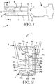
- the electrical connector 2 includes a conductor engaging end 4 and a contact end 6 interconnected by an intermediate portion 8.
- the conductor engaging end 4 of the present embodiment is adapted for crimp engagement of an insulated conductor by what is commonly known as an F-crimp.
- the conductor engaging end 4 could take on any desired configuration depending upon the type of conductor to be engaged and the physical characteristics required of the engagement. Possible configurations would include, for wire, an insulation displacement contact (IDC) for engaging an insulated wire, different crimp structures, or solder structures, while it would be also possible to incorporate structure for direct engagement of pads on a printed circuit board or another connector structure.
- IDC insulation displacement contact
- the contact end 6 includes an outer shell 10 that generally surrounds an inner contact 12.
- the outer shell 10 is a stamped and formed sheet metal component joined together along seam 14 by conventional techniques, such as laser welding, to form a protective box about the inner contact 12.
- At the front end of the outer shell 10 extend forwardly a pair of opposing guide tabs 16 that are folded backwards and inwardly to define a mouth 18 therebetween for receiving the mating tab terminal (not shown).
- the guide tabs 16 act to assist in blind mating and to protect the inner contact 12 during insertion of the tab terminal (not shown).
- a rear end 20 which extends out over the intermediate portion 8 to define side receiving regions 22.
- These side receiving regions 22 may receive a secondary locking member (not shown) of a connector housing (not shown) in order to provide positive retention of the terminal within the housing, as is well known in the art.
- a secondary locking member not shown
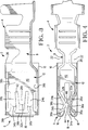
- the inner contact 12 includes three pairs of opposed contact arms at 24a,b; 26a,b; 28a,b including respectively thereupon contact surfaces 30a,b; 32a,b; 34a,b.
- Correspondingly disposed contact arms of the outer pairs 24a,28a; 24b,28b are advantageously, although not necessarily, interconnected at their forward end by a tie bar 36a,36b respectively.
- Each tie bar 36a,36b is integrally formed with opposing side rails 38a,38b that act to stiffen the corresponding contact arms 24a,b;28a,b as will be described below.
- the receptacle terminal need not be formed of opposing pairs of contact arms and it is envisioned that the receptacle structure could include an opposite side that is a seat with contact surfaces thereupon having no or different resiliency characteristics than the side illustrated here in Figure 3 incorporating the present invention.
- the contact arms 24b,26b,28b and the oppositely opposed side rails 38b extend from a common base portion 40b.
- the outer contact arms 24b,28b and the opposing side rails 38b are interconnected at the tie bar 36b.
- the side rails 38 are folded normal to the plane from which the contact arms 24b,28b are formed disposed transversely to act as stiffening members for re-enforcing the cantilevered nature of the contact arms 24b,28b.
- the side rails 38b provide additional stiffness beyond what would be realized if the contact arms 24b,28b were simply cantilevered from the base 40.
- tie bar 36b interconnects corresponding contact arms 24b,28b, when forces resulting from the insertion of a tab terminal are exerted upon one of the contact arms 24b,28b, the tie bar 36b transmits at least a portion of reactionary forces through to the opposite contact arm 24b,28b and side rail 38b.
- the centre contact arm 26b is located between the outer contact arms 24b,28b in a freely cantilevered manner extending forwardly from the base 40.
- This contact arm 26 is defined by a U-shaped opening 42 that defines a free end 43 of the contact arm 26b.
- the outer contact arms 24a,b;28a,b extend forwardly from the base 40 and converge towards the opposing arm of the pair to define a first receiving region 44 between the opposed contact surfaces 30a,b and 34a,b of the respective contact arms before diverging outwardly.
- the first contact receiving region 44 is forward a second receiving region 46 defined by the contact surfaces 32a,b of the middle pair of contact arms 26a,b which converge and diverge in a manner similar to that described with respect to the outer contact arms.
- the contact surfaces 30a,b;34a,b of the outer pairs of contact arms 24a,b;28a,b are spaced further apart, thereby defining a larger first receiving region than the contact surfaces 32a,b of the middle contact arms. It may be desirable in some instances to have the opposing contact surfaces 30a,b;34a,b and 32a,b that define the first and second receiving regions 44,46 respectively in contact with each other prior to insertion of the mating tab terminal.
- the second receiving region 46 slightly smaller than the first receiving region 44 is may be assured that these contact arms 26 will engage the tab terminal and the amount of normal forces generated.
- the central pair of contact arms 26 being freely cantilevered they have a greater elastic range enabling these arms to compensate for misalignment of the mating tab terminal.
- these arms are located at the centre position where the minimal amount of displacement occurs if the tab terminal is misaligned, thereby assuring that at least two points of contact will be formed on each side of the tab terminal.
- stiffer outer contact arms 24a,b;28a,b are reinforced by side rails
- other stiffening structure could be used, for example: a back up spring; forming techniques, such as coining or stamping; or alternative structural configurations that would enable stiffening of a contact arm from its freely cantilevered stiffness characteristic.
- a receptacle terminal is produced that is especially suited for ensuring that multiple points of contact are established with a mating tab terminal, in order to enable adequate signal transmission, even where the mating tab terminal is misaligned.
- the receptacle terminal has good insertion force characteristics in relation to the number of contact points.
- the receptacle terminal generates sufficient normal force to retain the mated tab terminal therein.
Applications Claiming Priority (2)
| Application Number | Priority Date | Filing Date | Title |
|---|---|---|---|
| GB9417702A GB9417702D0 (en) | 1994-09-02 | 1994-09-02 | Electrical receptacle terminal |
| GB9417702 | 1994-09-02 |
Publications (3)
| Publication Number | Publication Date |
|---|---|
| EP0700122A2 true EP0700122A2 (de) | 1996-03-06 |
| EP0700122A3 EP0700122A3 (de) | 1999-03-03 |
| EP0700122B1 EP0700122B1 (de) | 2001-11-14 |
Family
ID=10760755
Family Applications (1)
| Application Number | Title | Priority Date | Filing Date |
|---|---|---|---|
| EP95113791A Expired - Lifetime EP0700122B1 (de) | 1994-09-02 | 1995-09-01 | Elektrische Buchse |
Country Status (3)
| Country | Link |
|---|---|
| EP (1) | EP0700122B1 (de) |
| DE (1) | DE69523839T2 (de) |
| GB (1) | GB9417702D0 (de) |
Cited By (10)
| Publication number | Priority date | Publication date | Assignee | Title |
|---|---|---|---|---|
| EP0833409A1 (de) * | 1996-09-30 | 1998-04-01 | The Whitaker Corporation | Elektrische Anschlussklemme |
| US5938485A (en) * | 1996-09-30 | 1999-08-17 | The Whitaker Corporation | Electrical terminal |
| EP0969559A2 (de) * | 1998-06-29 | 2000-01-05 | The Whitaker Corporation | Elektrische Anschlussbuchse |
| EP1045480A2 (de) * | 1999-04-15 | 2000-10-18 | Robert Bosch Gmbh | Federarmkontaktelement |
| EP1122830A1 (de) * | 2000-01-31 | 2001-08-08 | Tyco Electronics AMP GmbH | Kontaktbuchse |
| EP1122831A2 (de) * | 2000-01-31 | 2001-08-08 | Tyco Electronics AMP GmbH | Kontaktbuchse |
| EP1148588A2 (de) * | 2000-01-31 | 2001-10-24 | Tyco Electronics AMP GmbH | Kontaktbuchse |
| EP2485334A1 (de) * | 2011-02-04 | 2012-08-08 | Sumitomo Wiring Systems, Ltd. | Mehrfacher Anschlusskontakt |
| EP2544309A1 (de) * | 2011-07-04 | 2013-01-09 | Sumitomo Wiring Systems, Ltd. | Anschlussstück und Verfahren für dessen Herstellung |
| WO2013121497A1 (en) * | 2012-02-16 | 2013-08-22 | Yazaki Corporation | Joint terminal and joint connector |
Families Citing this family (1)
| Publication number | Priority date | Publication date | Assignee | Title |
|---|---|---|---|---|
| US11201427B2 (en) * | 2020-01-28 | 2021-12-14 | TE Connectivity Services Gmbh | Socket contact for an electrical connector |
Family Cites Families (5)
| Publication number | Priority date | Publication date | Assignee | Title |
|---|---|---|---|---|
| JPS6358776A (ja) * | 1986-08-27 | 1988-03-14 | アンプ インコ−ポレ−テツド | レセプタクルコンタクト |
| FR2621180B1 (fr) * | 1987-09-28 | 1990-01-12 | Francelco Sa | Borne de contact electrique de type cage |
| FR2647602A1 (fr) * | 1989-05-25 | 1990-11-30 | Amp France | Contact femelle |
| US4975066A (en) * | 1989-06-27 | 1990-12-04 | Amp Incorporated | Coaxial contact element |
| GB9208205D0 (en) * | 1992-04-14 | 1992-05-27 | Amp Gmbh | Electrical socket terminal |
-
1994
- 1994-09-02 GB GB9417702A patent/GB9417702D0/en active Pending
-
1995
- 1995-09-01 DE DE69523839T patent/DE69523839T2/de not_active Expired - Lifetime
- 1995-09-01 EP EP95113791A patent/EP0700122B1/de not_active Expired - Lifetime
Non-Patent Citations (1)
| Title |
|---|
| None |
Cited By (14)
| Publication number | Priority date | Publication date | Assignee | Title |
|---|---|---|---|---|
| EP0833409A1 (de) * | 1996-09-30 | 1998-04-01 | The Whitaker Corporation | Elektrische Anschlussklemme |
| US5938485A (en) * | 1996-09-30 | 1999-08-17 | The Whitaker Corporation | Electrical terminal |
| EP0969559A2 (de) * | 1998-06-29 | 2000-01-05 | The Whitaker Corporation | Elektrische Anschlussbuchse |
| EP1045480A2 (de) * | 1999-04-15 | 2000-10-18 | Robert Bosch Gmbh | Federarmkontaktelement |
| EP1045480A3 (de) * | 1999-04-15 | 2001-07-11 | Robert Bosch Gmbh | Federarmkontaktelement |
| EP1122831A2 (de) * | 2000-01-31 | 2001-08-08 | Tyco Electronics AMP GmbH | Kontaktbuchse |
| EP1122830A1 (de) * | 2000-01-31 | 2001-08-08 | Tyco Electronics AMP GmbH | Kontaktbuchse |
| EP1122831A3 (de) * | 2000-01-31 | 2001-09-26 | Tyco Electronics AMP GmbH | Kontaktbuchse |
| EP1148588A2 (de) * | 2000-01-31 | 2001-10-24 | Tyco Electronics AMP GmbH | Kontaktbuchse |
| EP1148588A3 (de) * | 2000-01-31 | 2001-11-14 | Tyco Electronics AMP GmbH | Kontaktbuchse |
| EP2485334A1 (de) * | 2011-02-04 | 2012-08-08 | Sumitomo Wiring Systems, Ltd. | Mehrfacher Anschlusskontakt |
| US8616925B2 (en) | 2011-02-04 | 2013-12-31 | Sumitomo Wiring Systems, Ltd. | Multi-contact terminal fitting |
| EP2544309A1 (de) * | 2011-07-04 | 2013-01-09 | Sumitomo Wiring Systems, Ltd. | Anschlussstück und Verfahren für dessen Herstellung |
| WO2013121497A1 (en) * | 2012-02-16 | 2013-08-22 | Yazaki Corporation | Joint terminal and joint connector |
Also Published As
| Publication number | Publication date |
|---|---|
| DE69523839D1 (de) | 2001-12-20 |
| GB9417702D0 (en) | 1994-10-19 |
| EP0700122B1 (de) | 2001-11-14 |
| DE69523839T2 (de) | 2002-05-29 |
| EP0700122A3 (de) | 1999-03-03 |
Similar Documents
| Publication | Publication Date | Title |
|---|---|---|
| EP0678936B1 (de) | Reibkorrosionsfreie Miniatur-Steckbuchse | |
| US5653616A (en) | Electrical receptacle terminal | |
| EP1428297B1 (de) | Elektrische Verbinder und Anschlussstück für Starkstrom in Kraftfahrzeugen | |
| EP0848454B1 (de) | Elektrischer Kontakt | |
| EP0727842B1 (de) | Einstückige Ansschlussbüchse | |
| JP2706309B2 (ja) | 電気コネクタ組立体 | |
| US5741162A (en) | Electrical contact having improved locking lances | |
| EP1120861B1 (de) | Elektrischer Verbinder mit verbesserter Kontaktbüchse | |
| EP0700122B1 (de) | Elektrische Buchse | |
| US5624289A (en) | High current receptacle terminal | |
| US5980297A (en) | Lock arm deformation prevention construction | |
| WO1995031017A1 (en) | Universal contact receptacle | |
| US5775962A (en) | Joining structure for box-shaped portion of terminal lug | |
| EP1089387A2 (de) | Modulare elektrische Anschlussbuchse | |
| US7118428B2 (en) | Female terminal for the electrically conductive connection to a terminal pin, especially a flat-pin terminal | |
| EP0708499A2 (de) | Anschlussbuchse mit Kurzschlussfederkontakten | |
| US5122083A (en) | Resilient terminal with buckling prevention mechanism | |
| JP3304690B2 (ja) | 相互接続用端子及びジョイントコネクタ | |
| EP0727843B1 (de) | Asymmetrisches elektrisches Kontaktgehäuse | |
| US20020055297A1 (en) | Modular female electrical terminal | |
| US5795196A (en) | Contact having an independently supported inner contact arm | |
| WO1998002938A1 (en) | Female electrical terminal with torsion members | |
| EP0979543B1 (de) | Elektrische kontaktfeder | |
| JP2772325B2 (ja) | 雄端子結合用中継端子 | |
| JP2596685Y2 (ja) | 圧着タイプコネクタ |
Legal Events
| Date | Code | Title | Description |
|---|---|---|---|
| PUAI | Public reference made under article 153(3) epc to a published international application that has entered the european phase |
Free format text: ORIGINAL CODE: 0009012 |
|
| AK | Designated contracting states |
Kind code of ref document: A2 Designated state(s): DE ES FR GB IT |
|
| PUAL | Search report despatched |
Free format text: ORIGINAL CODE: 0009013 |
|
| AK | Designated contracting states |
Kind code of ref document: A3 Designated state(s): DE ES FR GB IT |
|
| 17P | Request for examination filed |
Effective date: 19990810 |
|
| 17Q | First examination report despatched |
Effective date: 19991108 |
|
| GRAG | Despatch of communication of intention to grant |
Free format text: ORIGINAL CODE: EPIDOS AGRA |
|
| GRAG | Despatch of communication of intention to grant |
Free format text: ORIGINAL CODE: EPIDOS AGRA |
|
| GRAH | Despatch of communication of intention to grant a patent |
Free format text: ORIGINAL CODE: EPIDOS IGRA |
|
| GRAH | Despatch of communication of intention to grant a patent |
Free format text: ORIGINAL CODE: EPIDOS IGRA |
|
| GRAA | (expected) grant |
Free format text: ORIGINAL CODE: 0009210 |
|
| AK | Designated contracting states |
Kind code of ref document: B1 Designated state(s): DE ES FR GB IT |
|
| REF | Corresponds to: |
Ref document number: 69523839 Country of ref document: DE Date of ref document: 20011220 |
|
| REG | Reference to a national code |
Ref country code: GB Ref legal event code: IF02 |
|
| ET | Fr: translation filed | ||
| PG25 | Lapsed in a contracting state [announced via postgrant information from national office to epo] |
Ref country code: ES Free format text: LAPSE BECAUSE OF FAILURE TO SUBMIT A TRANSLATION OF THE DESCRIPTION OR TO PAY THE FEE WITHIN THE PRESCRIBED TIME-LIMIT Effective date: 20020530 |
|
| PLBE | No opposition filed within time limit |
Free format text: ORIGINAL CODE: 0009261 |
|
| STAA | Information on the status of an ep patent application or granted ep patent |
Free format text: STATUS: NO OPPOSITION FILED WITHIN TIME LIMIT |
|
| 26N | No opposition filed | ||
| PGFP | Annual fee paid to national office [announced via postgrant information from national office to epo] |
Ref country code: GB Payment date: 20040812 Year of fee payment: 10 |
|
| PGFP | Annual fee paid to national office [announced via postgrant information from national office to epo] |
Ref country code: FR Payment date: 20040902 Year of fee payment: 10 |
|
| PG25 | Lapsed in a contracting state [announced via postgrant information from national office to epo] |
Ref country code: IT Free format text: LAPSE BECAUSE OF NON-PAYMENT OF DUE FEES Effective date: 20050901 Ref country code: GB Free format text: LAPSE BECAUSE OF NON-PAYMENT OF DUE FEES Effective date: 20050901 |
|
| GBPC | Gb: european patent ceased through non-payment of renewal fee |
Effective date: 20050901 |
|
| PG25 | Lapsed in a contracting state [announced via postgrant information from national office to epo] |
Ref country code: FR Free format text: LAPSE BECAUSE OF NON-PAYMENT OF DUE FEES Effective date: 20060531 |
|
| REG | Reference to a national code |
Ref country code: FR Ref legal event code: ST Effective date: 20060531 |
|
| PGFP | Annual fee paid to national office [announced via postgrant information from national office to epo] |
Ref country code: DE Payment date: 20140929 Year of fee payment: 20 |
|
| REG | Reference to a national code |
Ref country code: DE Ref legal event code: R071 Ref document number: 69523839 Country of ref document: DE |