EP0699594A1 - Dual compartment receptacle - Google Patents
Dual compartment receptacle Download PDFInfo
- Publication number
- EP0699594A1 EP0699594A1 EP95111890A EP95111890A EP0699594A1 EP 0699594 A1 EP0699594 A1 EP 0699594A1 EP 95111890 A EP95111890 A EP 95111890A EP 95111890 A EP95111890 A EP 95111890A EP 0699594 A1 EP0699594 A1 EP 0699594A1
- Authority
- EP
- European Patent Office
- Prior art keywords
- plunger
- chamber
- plug
- cap
- stopper
- Prior art date
- Legal status (The legal status is an assumption and is not a legal conclusion. Google has not performed a legal analysis and makes no representation as to the accuracy of the status listed.)
- Granted
Links
Images

Classifications
-
- B—PERFORMING OPERATIONS; TRANSPORTING
- B65—CONVEYING; PACKING; STORING; HANDLING THIN OR FILAMENTARY MATERIAL
- B65D—CONTAINERS FOR STORAGE OR TRANSPORT OF ARTICLES OR MATERIALS, e.g. BAGS, BARRELS, BOTTLES, BOXES, CANS, CARTONS, CRATES, DRUMS, JARS, TANKS, HOPPERS, FORWARDING CONTAINERS; ACCESSORIES, CLOSURES, OR FITTINGS THEREFOR; PACKAGING ELEMENTS; PACKAGES
- B65D81/00—Containers, packaging elements, or packages, for contents presenting particular transport or storage problems, or adapted to be used for non-packaging purposes after removal of contents
- B65D81/32—Containers, packaging elements, or packages, for contents presenting particular transport or storage problems, or adapted to be used for non-packaging purposes after removal of contents for packaging two or more different materials which must be maintained separate prior to use in admixture
- B65D81/3205—Separate rigid or semi-rigid containers joined to each other at their external surfaces
- B65D81/3211—Separate rigid or semi-rigid containers joined to each other at their external surfaces coaxially and provided with means facilitating admixture
Definitions
- the invention relates to a two-chamber container according to the preamble of claim 1.
- Such a container is known, for example, from the generic DE-U-89 00 291 of the applicant. This container is used to store two different liquid products separately until use. For use, the products are combined into a mixture which can then be removed via a closure.
- the invention has for its object to provide a generic container with which it is possible with simple handling to additionally remove a limited subset of only one product.
- a tubular plunger is provided which is connected in a basic position on the one hand with its first end to the threaded portion of the plunger and on the other hand protrudes with its other second end through the plug into the lower chamber, the plunger with the plug being liquid-tight is connected, a limited subset of only one product can be removed from the lower chamber.
- This is advantageous, for example, in terms of application technology in the hairdressing sector, initially only with one Product in a limited amount to carry out a first hair treatment step. For a second hair treatment step with a product mixture, a cap is turned, then the container is shaken briefly and then applied.
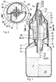
- FIG. 1 A first exemplary embodiment of a two-chamber container 1 is shown in FIG. 1.
- the container 1 is used for separate, flowable substances 2, 3, a waist bottle 6 with plugs 8 arranged in a waist plane 7 being provided for separating an upper and lower chamber 4, 5.
- the stopper 8 is pressed into the lower chamber 5 by manually rotating a rotary cap 9 by means of a plunger 10 from the waist plane 7, the rotary cap 9 for this purpose pointing into the upper chamber 4
- Thread 11 is provided and a threaded portion 12 arranged on the plunger 10 engages in the thread 11 of the rotary cap 9 like a spindle drive.
- the plunger 10 is of tubular design, which in a basic position is connected on the one hand with its first end (30) to the threaded section 12 of the plunger 10 in a liquid-tight manner and on the other hand projects with its other second end (31) through the plug 8 into the lower chamber 5 , wherein the plunger 10 is connected to the plug 8 in a liquid-tight manner.
- FIG. 1 shows the container 1 in a storage state, that is to say before the substances 2, 3 are removed; the right-hand side of FIG. 1 shows the container 1 with the plug 8 pressed into the lower chamber 5 and with a mixture of substances 2, 3, part of the substance 3 having been removed beforehand through the pipe 15 projecting into the chamber 5.
- the upper chamber 4 being provided with two opposite bottle wall indentations 20, 20A, which in interaction with the vanes 18 represent a guide sliding bearing or an anti-rotation device for the plunger 10 for a kind of spindle drive for the plunger 10.
- the lower chamber 5 of the waist bottle 6 without the rotating cap 9 and plunger 10 / stopper 8 is first filled with a liquid substance 3 via an opening 16. Then the plug 8 is pressed together with the plunger 10 into the opening 16.
- the tubular plunger 10 is provided with a driving ring 21 which is dimensioned such that the plug 8 can be pressed into the seat of the waist opening 16 by the axial force of the plunger 10.
- the cap 9 is screwed onto the threaded section 12 and bounced onto the locking ring 17.
- the closure 14 is first opened and a quantity of the substance 3 limited by the predetermined length of the tube 15 is removed.
- these are first merged in that by rotating the cap 9 of the driving ring 21 pushes the stopper 8 down into the lower chamber 5, whereby the substance 2 flows from the upper chamber 4 through the now cleared opening 16 into the lower chamber 5 and by shaking the container 1 results in a mixture of substances 2, 3.
- the plug 8 can consist of a material that is particularly suitable for this with regard to its sealing property.
- the end of the chamber separation lifting process is signaled by the fact that the lower end of the wings 18 strikes a bottom 22 of the upper chamber 4 and thereby prevents the cap 9 from rotating further (right side of FIG. 1).
- the substances 2, 3 thicken during the mixing process.
- the closure part 23 with its relatively small opening 24 can be made breakable by means of a break-off ring 25, as a result of which a larger removal opening 26 is reached.
- the plunger 10A and the stopper 8A are designed in one piece, as a result of which a part is reduced.
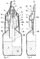
- the left side of FIG. 3 shows the container 1A in a storage state or before use; the right-hand side of FIG. 3 shows the container 1A after the chamber separation has been lifted.
- FIG. 4 shows the container 1A according to FIG. 3 in a position immediately after the two substances 2, 3 have been filled, for which purpose the container 1A is still without a rotating cap 9 and the stopper 8A has a higher-lying closure position.
- the lower chamber 5 can be filled with a substance 3 through the opening 16 and after the plug 8A has been placed on it, the upper chamber 4 can be filled with a substance 2 through the free-standing wings 18, as indicated by arrow 26.
- it can also be a simultaneous one Filling can be provided according to FIG. 4, namely simultaneous filling of the lower chamber 5 through the pipe 15A and the upper chamber 4 by arrow 26.
- the cap 9 is rotated on the threaded section 12 and finally chipped onto the locking ring 17. This bouncing process requires a certain axial path of the plug 8A, which is why the plug 8A has a correspondingly long configuration because of the sealing function.
- the plunger 10B is designed as an elongated plug 8B, as a result of which the plug 8B simultaneously acts as a tube 15B. Otherwise, the description according to FIGS. 5 and 6 applies.
Landscapes
- Engineering & Computer Science (AREA)
- Mechanical Engineering (AREA)
- Closures For Containers (AREA)
- Package Specialized In Special Use (AREA)
- Containers And Packaging Bodies Having A Special Means To Remove Contents (AREA)
Abstract
Description
Die Erfindung betrifft einen Zweikammerbehälter nach der Gattung des Oberbegriffs des Anspruchs 1.The invention relates to a two-chamber container according to the preamble of
Ein derartiger Behälter ist zum Beispiel durch die gattungsbildende DE-U-89 00 291 der Anmelderin bekannt. Dieser Behälter dient dazu, zwei verschiedene flüssige Produkte bis zum Gebrauch getrennt aufzubewahren. Zum Gebrauch werden die Produkte zu einer Mischung zusammengeführt, die dann über einen Verschluß entnehmbar ist.Such a container is known, for example, from the generic DE-U-89 00 291 of the applicant. This container is used to store two different liquid products separately until use. For use, the products are combined into a mixture which can then be removed via a closure.
Der Erfindung liegt die Aufgabe zugrunde, einen gattungsgleichen Behälter zu schaffen, mit dem es bei einfacher Handhabung möglich ist, zusätzlich eine begrenzte Teilmenge nur des einen Produkts zu entnehmen.The invention has for its object to provide a generic container with which it is possible with simple handling to additionally remove a limited subset of only one product.
Diese Aufgabe wird gelöst nach den Merkmalen des kennzeichnenden Teils des Anspruchs 1. Vorteilhafte Weiterbildungen/Ausgestaltungen der Erfindung gehen aus den Unteransprüchen hervor.This object is achieved according to the features of the characterizing part of
Dadurch, daß ein rohrartiger Stößel vorgesehen ist, der in einer Grundstellung einerseits mit seinem ersten Ende mit dem Gewindeabschnitt des Stößels flüssigkeitsdicht verbunden ist und andererseits mit seinem anderen zweiten Ende durch den Stopfen hindurch in die untere Kammer hineinragt, wobei der Stößel mit dem Stopfen flüssigkeitsdicht verbunden ist, ist eine begrenzte Teilmenge nur des einen Produkts aus der unteren Kammer entnehmbar. Dies ist beispielsweise anwendungstechnisch im Friseurbereich vorteilhaft, um zunächst nur mit dem einen Produkt in begrenzter Menge einen ersten Haarbehandlungsschritt vorzunehmen. Für einen zweiten Haarbehandlungsschritt mit einem Produktgemisch wird eine Kappe gedreht, dann der Behälter kurz geschüttelt und anschließend appliziert.Characterized in that a tubular plunger is provided which is connected in a basic position on the one hand with its first end to the threaded portion of the plunger and on the other hand protrudes with its other second end through the plug into the lower chamber, the plunger with the plug being liquid-tight is connected, a limited subset of only one product can be removed from the lower chamber. This is advantageous, for example, in terms of application technology in the hairdressing sector, initially only with one Product in a limited amount to carry out a first hair treatment step. For a second hair treatment step with a product mixture, a cap is turned, then the container is shaken briefly and then applied.
Anhand von drei Ausführungsbeispielen wird die Erfindung näher beschrieben.The invention is described in more detail using three exemplary embodiments.
Es zeigt:
Figur 1- in einem Axialschnitt ein erstes Ausführungsbeispiel;
Figur 2- einen Schnitt II-II nach der
Figur 1; Figur 3 und 4- in einem Axialschnitt ein zweites Ausführungsbeispiel;
Figur 5 und 6- in einem Axialschnitt ein drittes Ausführungsbeispiel.
- Figure 1
- in an axial section a first embodiment;
- Figure 2
- a section II-II of Figure 1;
- Figures 3 and 4
- in a axial section a second embodiment;
- Figures 5 and 6
- in a axial section a third embodiment.
Ein erstes Ausführungsbeispiel eines Zweikammerbehälters 1 ist in der Figur 1 dargestellt. Der Behälter 1 dient für getrennt zu haltende, fließfähige Stoffe 2, 3, wobei zur Trennung einer oberen und unteren Kammer 4, 5 eine Taillenflasche 6 mit in einer Taillenebene 7 angeordneten Stopfen 8 vorgesehen ist. Zum Zusammenführen der beiden Stoffe 2, 3 innerhalb des Behälters 1 wird der Stopfen 8 durch manuelles Drehen einer Drehkappe 9 durch einen Stößel 10 aus der Taillenebene 7 in die untere Kammer 5 hineingedrückt, wobei dazu die Drehkappe 9 mit einem in die obere Kammer 4 weisenden Gewinde 11 versehen ist und ein am Stößel 10 angeordneter Gewindeabschnitt 12 in das Gewinde 11 der Drehkappe 9 spindelantriebsartig eingreift. Im Endbereich des Gewindeabschnitts 12 sind Durchtrittsöffnungen 13 vorgesehen für einen Durchtritt der Stoffmischung 2, 3. Zum Entnehmen der Stoffe 2, 3 ist die Drehkappe 9 mit einem Verschluß 14 versehen. Der Stößel 10 ist rohrartig ausgestaltet, der in einer Grundstellung einerseits mit seinem ersten Ende (30) mit dem Gewindeabschnitt 12 des Stößels 10 flüssigkeitsdicht verbunden ist und andererseits mit seinem anderen zweiten Ende (31) durch den Stopfen 8 hindurch in die untere Kammer 5 hineinragt, wobei der Stößel 10 mit dem Stopfen 8 flüssigkeitsdicht verbunden ist.A first exemplary embodiment of a two-
Die linke Seite der Figur 1 zeigt den Behälter 1 in einem Lagerungszustand, also vor Entnahme der Stoffe 2, 3; die rechte Seite der Figur 1 zeigt den Behälter 1 mit in die untere Kammer 5 hineingedrücktem Stopfen 8 und mit einem Stoffgemisch 2, 3, wobei ein Teil des Stoffs 3 zuvor entnommen ist durch das in die Kammer 5 hineinragende Rohr 15. An dem Rohr 15 sind vier radial angeordnete Flügel 18 angeformt, wobei die obere Kammer 4 mit zwei gegenüberliegenden Flaschenwandeinbuchtungen 20, 20A versehen ist, die im Zusammenspiel mit den Flügeln 18 ein Führungsgleitlager bzw. eine Verdrehsicherung des Stößels 10 darstellen für eine Art Spindelantrieb des Stößels 10.The left side of FIG. 1 shows the
Zum Befüllen des Behälters 1 wird zunächst die untere Kammer 5 der Taillenflasche 6 ohne Drehkappe 9 und Stößel 10/Stopfen 8 über eine Öffnung 16 mit einem flüssigen Stoff 3 befüllt. Dann wird der Stopfen 8 zusammen mit dem Stößel 10 in die Öffnung 16 gedrückt. Dazu ist der rohrartige Stößel 10 mit einem Mitnehmering 21 versehen, der so bemessen ist, daß der Stopfen 8 von der Axialkraft des Stößels 10 in den Sitz der Taillenöffnung 16 gedrückt werden kann. Nach dem Befüllen der oberen Kammer 4 mit dem Stoff 2 erfolgt ein Aufdrehen der Kappe 9 auf den Gewindeabschnitt 12 und ein Aufprellen auf den Rastring 17.To fill the
Zum Entnehmen einer Teilmenge wird zunächst der Verschluß 14 geöffnet und eine durch die vorgegebene Länge des Rohrs 15 begrenzte Menge des Stoffs 3 entnommen. Zum weiteren Entnehmen eines Stoffgemisches 2, 3 werden diese zunächst dadurch zusammengeführt, daß durch Drehen der Kappe 9 der Mitnehmering 21 den Stopfen 8 nach unten in die untere Kammer 5 hineindrückt, wodurch der Stoff 2 aus der oberen Kammer 4 über die nun freigewordene Öffnung 16 in die untere Kammer 5 fließt und durch Schütteln des Behälters 1 eine Stoffmischung 2, 3 ergibt. Bei diesem Ausführungsbeispiel ist ein Vorteil darin zu sehen, daß der Stopfen 8 hinsichtlich seiner Dichtungseigenschaft aus einem hierzu besonders geeigneten Material bestehen kann. Das Ende des Kammertrennungsaufhebevorgangs wird dadurch signalisiert, daß das untere Ende der Flügel 18 auf einen Boden 22 der oberen Kammer 4 aufstößt und dadurch ein weiteres Drehen der Kappe 9 verhindert wird (rechte Seite der Figur 1). Es kann anwendungstechnisch vorgesehen werden, daß die Stoffe 2, 3 beim Vermischungsvorgang sich verdicken. Hierzu ist zwecks besserer Entnahme der verdickten Stoffmischung 2, 3 vorgesehen, den Verschlußteil 23 mit seiner relativ kleinen Öffnung 24 abbrechbar mittels eines Abbrechringes 25 auszubilden, wodurch eine größere Entnahmeöffnung 26 erreicht ist.To remove a partial quantity, the
Beim zweiten Ausführungsbeispiel eines Behälters 1A nach den Figuren 3 und 4 ist der Stößel 10A und der Stopfen 8A einteilig ausgestaltet, wodurch ein Teil reduziert ist. Die linke Seite der Figur 3 zeigt den Behälter 1A in einem Lagerungszustand bzw. vor Gebrauch; die rechte Seite der Figur 3 zeigt den Behälter 1A nach einer Aufhebung der Kammertrennung.In the second exemplary embodiment of a
Figur 4 zeigt den Behälter 1A nach der Figur 3 in einer Position unmittelbar nach dem Befüllen der beiden Stoffe 2, 3, wozu der Behälter 1A noch ohne Drehkappe 9 ist und der Stopfen 8A eine höherliegende Verschlußposition aufweist. Das Befüllen der unteren Kammer 5 mit einem Stoff 3 kann durch die Öffnung 16 erfolgen und nach dem Aufsetzen des Stopfens 8A das Befüllen der oberen Kammer 4 mit einem Stoff 2 durch die freistehenden Flügel 18, wie nach Pfeil 26 angedeutet. Es kann aber auch ein gleichzeitiges Befüllen nach der Figur 4 vorgesehen werden, nämlich gleichzeitiges Befüllen der unteren Kammer 5 durch das Rohr 15A und der oberen Kammer 4 durch Pfeil 26. Nach dem Befüllungsvorgang wird auf den Gewindeabschnitt 12 die Kappe 9 gedreht und abschließend auf den Rastring 17 geprellt. Dieser Prellvorgang macht einen gewissen axialen Weg des Stopfens 8A erforderlich, weswegen der Stopfen 8A eine entsprechend lange Ausgestaltung wegen der Dichtfunktion aufweist.FIG. 4 shows the
Beim dritten Ausführungsbeispiel eines Behälters 1B nach den Figuren 5 und 6 ist der Stößel 10B als ein verlängerter Stopfen 8B ausgestaltet, wodurch der Stopfen 8B gleichzeitig als Rohr 15B wirkt. Ansonsten gilt die Beschreibung nach der Figuren 5 und 6.In the third exemplary embodiment of a
Claims (6)
dadurch gekennzeichnet,
daß ein rohrartiger Stößel (10, 10A, 10B) vorgesehen ist, der in einer Grundstellung einerseits mit seinem ersten Ende (30) mit dem Gewindeabschnitt (12) des Stößels (10, 10A, 10B) flüssigkeitsdicht verbunden ist und andererseits mit seinem anderen zweiten Ende (31) durch den Stopfen (8, 8A, 8B) hindurch in die untere Kammer (5) hineinragt, wobei der Stößel (10, 10A, 10B) mit dem Stopfen (8, 8A, 8B) flüssigkeitsdicht verbunden ist.Two-chamber container for flowable materials to be kept separately, whereby a waist bottle with plugs arranged in a waist plane is provided for separating an upper and lower chamber, which is used to bring the two substances together within the container by manually turning a rotating cap through a plunger from the waist plane into the lower chamber is pressed in, for this purpose the rotary cap is provided with a thread pointing into the upper chamber and a threaded portion arranged on the plunger engages in the thread of the rotary cap in a manner such as to drive a spindle that through-openings are provided in the end region of the threaded portion, and that the rotary cap is provided with a closure is for removing the fabrics,
characterized,
that a tubular plunger (10, 10A, 10B) is provided, which is connected in a basic position on the one hand with its first end (30) to the threaded portion (12) of the plunger (10, 10A, 10B) and on the other hand with its other second End (31) projects through the plug (8, 8A, 8B) into the lower chamber (5), the plunger (10, 10A, 10B) being connected to the plug (8, 8A, 8B) in a liquid-tight manner.
Applications Claiming Priority (2)
| Application Number | Priority Date | Filing Date | Title |
|---|---|---|---|
| DE4428096A DE4428096A1 (en) | 1994-08-09 | 1994-08-09 | Two-chamber container |
| DE4428096 | 1994-08-09 |
Publications (2)
| Publication Number | Publication Date |
|---|---|
| EP0699594A1 true EP0699594A1 (en) | 1996-03-06 |
| EP0699594B1 EP0699594B1 (en) | 1997-08-27 |
Family
ID=6525221
Family Applications (1)
| Application Number | Title | Priority Date | Filing Date |
|---|---|---|---|
| EP95111890A Expired - Lifetime EP0699594B1 (en) | 1994-08-09 | 1995-07-28 | Dual compartment receptacle |
Country Status (4)
| Country | Link |
|---|---|
| US (1) | US5613623A (en) |
| EP (1) | EP0699594B1 (en) |
| JP (1) | JPH0858852A (en) |
| DE (2) | DE4428096A1 (en) |
Families Citing this family (62)
| Publication number | Priority date | Publication date | Assignee | Title |
|---|---|---|---|---|
| IT240641Y1 (en) * | 1996-05-08 | 2001-04-02 | Inge Spa | BOTTLE FOR SEPARATE STORAGE OF SUBSTANCES AND SUBSEQUENT DROP DISPENSING OF THE MIXTURE OF THESE SUBSTANCES |
| FR2751941B1 (en) * | 1996-08-02 | 1998-09-11 | Oreal | DEVICE FOR THE SEPARATE PACKAGING OF TWO COMPONENTS, THEIR MIXING AND THE DISTRIBUTION OF THE MIXTURE THUS OBTAINED |
| FR2751942B1 (en) * | 1996-08-02 | 1998-09-11 | Oreal | DEVICE FOR THE SEPARATE STORAGE OF TWO COMPONENTS THEIR MIXTURE AND THE DISTIBUTION OF THE MIXTURE |
| US6045254A (en) * | 1996-12-26 | 2000-04-04 | M.L.I.S. Projects Ltd. | Container having two or more compartments |
| US6113257A (en) * | 1996-12-26 | 2000-09-05 | M.L.I.S. Projects Ltd. | Two-compartment container |
| FR2765859B1 (en) * | 1997-07-08 | 1999-09-24 | Oreal | DEVICE FOR PACKAGING TWO COMPONENTS |
| FR2767794B1 (en) * | 1997-08-29 | 1999-10-08 | Oreal | SET OF TWO FREE MOUNTED ROTATING ELEMENTS IN RELATION TO THE OTHER, IN PARTICULAR FOR A MIXER IN THE FIELD OF HAIR COLORING |
| IL124609A0 (en) | 1998-05-22 | 1998-12-06 | Mlis Projects Ltd | Method and container for providing cocktails |
| BR0110574A (en) * | 2000-05-03 | 2003-04-01 | Amcad Holdings Ltd | Multiple Component Mix |
| US8512718B2 (en) | 2000-07-03 | 2013-08-20 | Foamix Ltd. | Pharmaceutical composition for topical application |
| WO2002062173A1 (en) * | 2001-02-05 | 2002-08-15 | Rachel Stevenson | Cosmetic device and method |
| JP2003164508A (en) * | 2001-12-03 | 2003-06-10 | Taisei Kako Co Ltd | Transfusion container |
| WO2003047981A2 (en) * | 2001-12-06 | 2003-06-12 | Gabriel Cabelli | Hand held fluent dispensing containers |
| US6758411B2 (en) | 2002-08-09 | 2004-07-06 | S. C. Johnson & Son, Inc. | Dual bottle for even dispensing of two flowable compositions |
| US6583103B1 (en) | 2002-08-09 | 2003-06-24 | S.C. Johnson & Son, Inc. | Two part cleaning formula resulting in an effervescent liquid |
| IL152486A0 (en) | 2002-10-25 | 2003-05-29 | Meir Eini | Alcohol-free cosmetic and pharmaceutical foam carrier |
| US20080138296A1 (en) | 2002-10-25 | 2008-06-12 | Foamix Ltd. | Foam prepared from nanoemulsions and uses |
| US8486376B2 (en) | 2002-10-25 | 2013-07-16 | Foamix Ltd. | Moisturizing foam containing lanolin |
| US8900554B2 (en) | 2002-10-25 | 2014-12-02 | Foamix Pharmaceuticals Ltd. | Foamable composition and uses thereof |
| US7700076B2 (en) | 2002-10-25 | 2010-04-20 | Foamix, Ltd. | Penetrating pharmaceutical foam |
| US9668972B2 (en) | 2002-10-25 | 2017-06-06 | Foamix Pharmaceuticals Ltd. | Nonsteroidal immunomodulating kit and composition and uses thereof |
| US9265725B2 (en) | 2002-10-25 | 2016-02-23 | Foamix Pharmaceuticals Ltd. | Dicarboxylic acid foamable vehicle and pharmaceutical compositions thereof |
| CA2502986C (en) | 2002-10-25 | 2011-08-23 | Foamix Ltd. | Cosmetic and pharmaceutical foam |
| US20070292461A1 (en) * | 2003-08-04 | 2007-12-20 | Foamix Ltd. | Oleaginous pharmaceutical and cosmetic foam |
| US10117812B2 (en) | 2002-10-25 | 2018-11-06 | Foamix Pharmaceuticals Ltd. | Foamable composition combining a polar solvent and a hydrophobic carrier |
| US7820145B2 (en) | 2003-08-04 | 2010-10-26 | Foamix Ltd. | Oleaginous pharmaceutical and cosmetic foam |
| US7704518B2 (en) | 2003-08-04 | 2010-04-27 | Foamix, Ltd. | Foamable vehicle and pharmaceutical compositions thereof |
| US9211259B2 (en) * | 2002-11-29 | 2015-12-15 | Foamix Pharmaceuticals Ltd. | Antibiotic kit and composition and uses thereof |
| US10729795B2 (en) * | 2004-01-12 | 2020-08-04 | Veltek Associates, Inc. | Method for mixing and dispensing |
| US7066354B2 (en) * | 2003-01-17 | 2006-06-27 | Stank Robert E | Mixing and dispensing apparatus |
| US6851580B2 (en) * | 2003-01-17 | 2005-02-08 | Veltek Associates, Inc. | Mixing and dispensing apparatus |
| US7575739B2 (en) | 2003-04-28 | 2009-08-18 | Foamix Ltd. | Foamable iodine composition |
| US8486374B2 (en) | 2003-08-04 | 2013-07-16 | Foamix Ltd. | Hydrophilic, non-aqueous pharmaceutical carriers and compositions and uses |
| US8795693B2 (en) | 2003-08-04 | 2014-08-05 | Foamix Ltd. | Compositions with modulating agents |
| US20080069779A1 (en) * | 2003-08-04 | 2008-03-20 | Foamix Ltd. | Foamable vehicle and vitamin and flavonoid pharmaceutical compositions thereof |
| CN1856294A (en) * | 2003-08-25 | 2006-11-01 | 弗米克斯有限公司 | Penetrating pharmaceutical foam |
| US20050186147A1 (en) * | 2004-02-04 | 2005-08-25 | Foamix Ltd. | Cosmetic and pharmaceutical foam with solid matter |
| US20070069046A1 (en) * | 2005-04-19 | 2007-03-29 | Foamix Ltd. | Apparatus and method for releasing a measure of content from a plurality of containers |
| US20080260655A1 (en) | 2006-11-14 | 2008-10-23 | Dov Tamarkin | Substantially non-aqueous foamable petrolatum based pharmaceutical and cosmetic compositions and their uses |
| US20080292560A1 (en) * | 2007-01-12 | 2008-11-27 | Dov Tamarkin | Silicone in glycol pharmaceutical and cosmetic compositions with accommodating agent |
| EP1986473B1 (en) * | 2007-04-03 | 2017-01-25 | Tsinghua University | Organic electroluminescent device |
| US8636982B2 (en) | 2007-08-07 | 2014-01-28 | Foamix Ltd. | Wax foamable vehicle and pharmaceutical compositions thereof |
| WO2009056991A2 (en) * | 2007-09-04 | 2009-05-07 | Foamix Ltd. | Device for delivery of a foamable composition |
| US9439857B2 (en) | 2007-11-30 | 2016-09-13 | Foamix Pharmaceuticals Ltd. | Foam containing benzoyl peroxide |
| WO2010041141A2 (en) | 2008-10-07 | 2010-04-15 | Foamix Ltd. | Oil-based foamable carriers and formulations |
| WO2009072007A2 (en) | 2007-12-07 | 2009-06-11 | Foamix Ltd. | Carriers, formulations, methods for formulating unstable active agents for external application and uses thereof |
| AU2009205314A1 (en) | 2008-01-14 | 2009-07-23 | Foamix Ltd. | Poloxamer foamable pharmaceutical compositions with active agents and/or therapeutic cells and uses |
| US20090308889A1 (en) * | 2008-06-11 | 2009-12-17 | Frank Lindsay | Container system |
| WO2010125470A2 (en) | 2009-04-28 | 2010-11-04 | Foamix Ltd. | Foamable vehicle and pharmaceutical compositions comprising aprotic polar solvents and uses thereof |
| CA2769677A1 (en) | 2009-07-29 | 2011-02-03 | Foamix Ltd. | Non surface active agent non polymeric agent hydro-alcoholic foamable compositions, breakable foams and their uses |
| CA2769625C (en) | 2009-07-29 | 2017-04-11 | Foamix Ltd. | Non surfactant hydro-alcoholic foamable compositions, breakable foams and their uses |
| US9849142B2 (en) | 2009-10-02 | 2017-12-26 | Foamix Pharmaceuticals Ltd. | Methods for accelerated return of skin integrity and for the treatment of impetigo |
| WO2011039637A2 (en) | 2009-10-02 | 2011-04-07 | Foamix Ltd. | Surfactant-free water-free foamable compositions, breakable foams and gels and their uses |
| US8550303B2 (en) | 2009-11-04 | 2013-10-08 | Colgate-Palmolive Company | Multi-chambered container |
| WO2012007843A2 (en) | 2010-07-12 | 2012-01-19 | Foamix Ltd. | Apparatus and method for releasing a unit dose of content from a container |
| US8523017B2 (en) | 2011-09-22 | 2013-09-03 | Veltek Associates, Inc. | Mixing and dispensing apparatus |
| US11242236B2 (en) | 2015-03-19 | 2022-02-08 | Phillip LaBarbera | Perfect pour drink mixer |
| AT517987B1 (en) * | 2015-11-24 | 2019-03-15 | Toifl Werner | shutter |
| MX2020012139A (en) | 2016-09-08 | 2021-01-29 | Vyne Pharmaceuticals Inc | Compositions and methods for treating rosacea and acne. |
| US10640275B2 (en) * | 2017-06-12 | 2020-05-05 | Bio-Techne Corportion | Dual chamber storage device |
| WO2019232499A1 (en) | 2018-06-01 | 2019-12-05 | In Spirit Group, Inc. | Multi-compartment beverage bottle system and method |
| GB201819975D0 (en) * | 2018-12-07 | 2019-01-23 | Windridge Katherine | A container |
Citations (2)
| Publication number | Priority date | Publication date | Assignee | Title |
|---|---|---|---|---|
| EP0243730A2 (en) * | 1986-04-09 | 1987-11-04 | Robert Finke Kommanditgesellschaft | Bottle with two compartments |
| DE8900291U1 (en) | 1989-01-12 | 1990-05-10 | Wella Ag, 6100 Darmstadt | Multi-chamber container for pourable substances |
Family Cites Families (8)
| Publication number | Priority date | Publication date | Assignee | Title |
|---|---|---|---|---|
| FR500073A (en) * | 1916-05-18 | 1920-03-02 | Stabilimenti Biak-Ing Adolfo Pouchain | Process for tin soldering or tinning of aluminum and its alloys |
| US2813649A (en) * | 1955-06-30 | 1957-11-19 | Lipari Michael | Receptacles |
| US3024947A (en) * | 1959-07-14 | 1962-03-13 | Chesebrough Ponds | Synthetic resin bottles |
| US3651990A (en) * | 1969-10-23 | 1972-03-28 | Edward J Cernei | Container for keeping liquids in separate condition and commingling and dispensing the same |
| DE2753737C2 (en) * | 1977-12-02 | 1984-04-19 | Wella Ag, 6100 Darmstadt | Container for two loose materials |
| FR2628075B1 (en) * | 1988-03-02 | 1990-08-17 | Merck Sharp & Dohme | PACKAGING AND DISPENSING ASSEMBLY FOR SEPARATING TWO COMPONENTS SEPARATELY, AND MAKING THEIR EXTEMPORANEOUS MIXTURE ON THE FIRST USE, AND METHOD FOR MANUFACTURING SUCH AN ASSEMBLY |
| FR2663304B1 (en) * | 1990-06-18 | 1992-09-25 | Lontrade Jean Pierre | COMPARTMENTAL SECURITY PACKAGING. |
| DE4326152A1 (en) * | 1993-08-04 | 1995-02-09 | Goldwell Ag | Twin-chamber package |
-
1994
- 1994-08-09 DE DE4428096A patent/DE4428096A1/en not_active Withdrawn
-
1995
- 1995-07-19 US US08/504,012 patent/US5613623A/en not_active Expired - Fee Related
- 1995-07-20 JP JP7207533A patent/JPH0858852A/en active Pending
- 1995-07-28 DE DE59500561T patent/DE59500561D1/en not_active Expired - Fee Related
- 1995-07-28 EP EP95111890A patent/EP0699594B1/en not_active Expired - Lifetime
Patent Citations (2)
| Publication number | Priority date | Publication date | Assignee | Title |
|---|---|---|---|---|
| EP0243730A2 (en) * | 1986-04-09 | 1987-11-04 | Robert Finke Kommanditgesellschaft | Bottle with two compartments |
| DE8900291U1 (en) | 1989-01-12 | 1990-05-10 | Wella Ag, 6100 Darmstadt | Multi-chamber container for pourable substances |
Also Published As
| Publication number | Publication date |
|---|---|
| DE4428096A1 (en) | 1996-02-15 |
| JPH0858852A (en) | 1996-03-05 |
| DE59500561D1 (en) | 1997-10-02 |
| US5613623A (en) | 1997-03-25 |
| EP0699594B1 (en) | 1997-08-27 |
Similar Documents
| Publication | Publication Date | Title |
|---|---|---|
| EP0699594B1 (en) | Dual compartment receptacle | |
| DE2753737C2 (en) | Container for two loose materials | |
| DE19831791B4 (en) | Cartridge-like container for holding two substances that come into contact with each other only when in use | |
| EP0558954A1 (en) | Metering pump for viscous, especially pasty products | |
| DE8504383U1 (en) | Tube-shaped container | |
| DE1280697B (en) | Closure device with double seal for two wash bottles containing different fluids | |
| DE1203176B (en) | Squeeze container with a number of individual chambers with flexible walls | |
| DE3833036A1 (en) | DOUBLE CHAMBER CONTAINER | |
| DE2704383C3 (en) | Molding device for a pack of coated paper containing a beverage | |
| EP0263313B1 (en) | Two component recipient | |
| EP0259852B1 (en) | Multichamber container | |
| EP1410840A2 (en) | Mixing element | |
| DE29821193U1 (en) | Mixing capsule | |
| EP0103600B1 (en) | Cap intended to be placed on the central outlet opening of a liquid container | |
| DE3631135C2 (en) | ||
| DE10200748A1 (en) | Lockable dispensing device for dispensing a liquid, viscous or pasty medium contained in a container | |
| DE19812153A1 (en) | Packing container of plastic for first and second flowable materials | |
| DE2400970C2 (en) | Mixing container for holding substances that react with one another for the production of ready-to-use dental preparations | |
| DE29820062U1 (en) | Two-component container | |
| DE3140398A1 (en) | Applicator seal for containers for receiving liquid products | |
| DE19861066C2 (en) | Plastic container for packaging a first and a second, flowable material, which are kept separate before being used in the mixed state | |
| DE1085307B (en) | Device for the joint delivery of at least two pastes from one container | |
| AT413095B (en) | Container for separated fluids | |
| DE8900291U1 (en) | Multi-chamber container for pourable substances | |
| DE102018007299B4 (en) | Multi-chamber beverage container |
Legal Events
| Date | Code | Title | Description |
|---|---|---|---|
| PUAI | Public reference made under article 153(3) epc to a published international application that has entered the european phase |
Free format text: ORIGINAL CODE: 0009012 |
|
| 17P | Request for examination filed |
Effective date: 19950728 |
|
| AK | Designated contracting states |
Kind code of ref document: A1 Designated state(s): DE FR GB IT |
|
| GRAG | Despatch of communication of intention to grant |
Free format text: ORIGINAL CODE: EPIDOS AGRA |
|
| GRAH | Despatch of communication of intention to grant a patent |
Free format text: ORIGINAL CODE: EPIDOS IGRA |
|
| 17Q | First examination report despatched |
Effective date: 19970123 |
|
| GRAH | Despatch of communication of intention to grant a patent |
Free format text: ORIGINAL CODE: EPIDOS IGRA |
|
| GRAA | (expected) grant |
Free format text: ORIGINAL CODE: 0009210 |
|
| AK | Designated contracting states |
Kind code of ref document: B1 Designated state(s): DE FR GB IT |
|
| PG25 | Lapsed in a contracting state [announced via postgrant information from national office to epo] |
Ref country code: IT Free format text: LAPSE BECAUSE OF FAILURE TO SUBMIT A TRANSLATION OF THE DESCRIPTION OR TO PAY THE FEE WITHIN THE PRE;WARNING: LAPSES OF ITALIAN PATENTS WITH EFFECTIVE DATE BEFORE 2007 MAY HAVE OCCURRED AT ANY TIME BEFORE 2007. THE CORRECT EFFECTIVE DATE MAY BE DIFFERENT FROM THE ONE RECORDED.SCRIBED TIME-LIMIT Effective date: 19970827 Ref country code: GB Free format text: LAPSE BECAUSE OF FAILURE TO SUBMIT A TRANSLATION OF THE DESCRIPTION OR TO PAY THE FEE WITHIN THE PRESCRIBED TIME-LIMIT Effective date: 19970827 Ref country code: FR Free format text: LAPSE BECAUSE OF FAILURE TO SUBMIT A TRANSLATION OF THE DESCRIPTION OR TO PAY THE FEE WITHIN THE PRESCRIBED TIME-LIMIT Effective date: 19970827 |
|
| REF | Corresponds to: |
Ref document number: 59500561 Country of ref document: DE Date of ref document: 19971002 |
|
| EN | Fr: translation not filed | ||
| GBV | Gb: ep patent (uk) treated as always having been void in accordance with gb section 77(7)/1977 [no translation filed] |
Effective date: 19970827 |
|
| PLBE | No opposition filed within time limit |
Free format text: ORIGINAL CODE: 0009261 |
|
| STAA | Information on the status of an ep patent application or granted ep patent |
Free format text: STATUS: NO OPPOSITION FILED WITHIN TIME LIMIT |
|
| 26N | No opposition filed | ||
| PGFP | Annual fee paid to national office [announced via postgrant information from national office to epo] |
Ref country code: DE Payment date: 20030710 Year of fee payment: 9 |
|
| PG25 | Lapsed in a contracting state [announced via postgrant information from national office to epo] |
Ref country code: DE Free format text: LAPSE BECAUSE OF NON-PAYMENT OF DUE FEES Effective date: 20050201 |