EP0699285B1 - Vorrichtung zum verbinden eines rohres mit einem kunststoff-hohlkörper - Google Patents
Vorrichtung zum verbinden eines rohres mit einem kunststoff-hohlkörper Download PDFInfo
- Publication number
- EP0699285B1 EP0699285B1 EP94917186A EP94917186A EP0699285B1 EP 0699285 B1 EP0699285 B1 EP 0699285B1 EP 94917186 A EP94917186 A EP 94917186A EP 94917186 A EP94917186 A EP 94917186A EP 0699285 B1 EP0699285 B1 EP 0699285B1
- Authority
- EP
- European Patent Office
- Prior art keywords
- pipe
- wall
- feed
- annular wall
- bush
- Prior art date
- Legal status (The legal status is an assumption and is not a legal conclusion. Google has not performed a legal analysis and makes no representation as to the accuracy of the status listed.)
- Expired - Lifetime
Links
- 239000004033 plastic Substances 0.000 title claims abstract description 26
- 229920003023 plastic Polymers 0.000 title claims abstract description 26
- 238000007789 sealing Methods 0.000 claims abstract description 41
- 239000002184 metal Substances 0.000 claims abstract description 13
- 230000035515 penetration Effects 0.000 claims abstract description 10
- 239000000463 material Substances 0.000 claims abstract description 3
- 238000000034 method Methods 0.000 abstract description 4
- 230000000149 penetrating effect Effects 0.000 description 6
- 239000012815 thermoplastic material Substances 0.000 description 4
- 230000005494 condensation Effects 0.000 description 2
- 238000009833 condensation Methods 0.000 description 2
- 230000000694 effects Effects 0.000 description 2
- 238000010438 heat treatment Methods 0.000 description 2
- 229920002430 Fibre-reinforced plastic Polymers 0.000 description 1
- 238000007599 discharging Methods 0.000 description 1
- 239000011151 fibre-reinforced plastic Substances 0.000 description 1
- 239000012530 fluid Substances 0.000 description 1
- 238000005259 measurement Methods 0.000 description 1
- 239000005060 rubber Substances 0.000 description 1
- 230000002459 sustained effect Effects 0.000 description 1
- 230000003313 weakening effect Effects 0.000 description 1
Images

Classifications
-
- F—MECHANICAL ENGINEERING; LIGHTING; HEATING; WEAPONS; BLASTING
- F16—ENGINEERING ELEMENTS AND UNITS; GENERAL MEASURES FOR PRODUCING AND MAINTAINING EFFECTIVE FUNCTIONING OF MACHINES OR INSTALLATIONS; THERMAL INSULATION IN GENERAL
- F16L—PIPES; JOINTS OR FITTINGS FOR PIPES; SUPPORTS FOR PIPES, CABLES OR PROTECTIVE TUBING; MEANS FOR THERMAL INSULATION IN GENERAL
- F16L47/00—Connecting arrangements or other fittings specially adapted to be made of plastics or to be used with pipes made of plastics
- F16L47/26—Connecting arrangements or other fittings specially adapted to be made of plastics or to be used with pipes made of plastics for branching pipes; for joining pipes to walls; Adaptors therefor
- F16L47/28—Joining pipes to walls or to other pipes, the axis of the joined pipe being perpendicular to the wall or to the axis of the other pipe
- F16L47/30—Joining pipes to walls or to other pipes, the axis of the joined pipe being perpendicular to the wall or to the axis of the other pipe using attaching means embracing the pipe
Definitions
- the present invention relates to a device for connecting a pipe to a hollow body with a plastic wall according to the preamble of claim 1.
- DE-B-1 178 312 discloses a device according to the preamble of claim 1.
- This known device comprises a feed-through pipe which is inserted from the inside into an opening in the wall of a plastic container for wind screen washer fluid.
- the pipe has a penetration edge which is forced into the wall by tensioning a nut which is fitted on the threaded stem of the pipe on the outside of the container.
- the inside of the container has to be accessable.
- Another generally known device comprises a metal feed-through pipe to which an outward projecting flange is welded.
- a flexible rubber sealing ring is placed between the flange and the outside of the wall of the body. The sealing ring is compressed and a seal is obtained by pulling the flange towards the hollow body using clamping means.
- This known device has the disadvantage that a reliable seal is not obtained in all situations with the flexible sealing ring.
- the object of the invention is to eliminate the abovementioned disadvantages and to provide a simple device which can be installed reliably for the connection of a pipe.
- a device of the type mentioned in the preamble which is characterized in that the fastening means comprise a first bush, an annular element to be fitted around the body for fixing the first bush around the opening disposed in the wall of the body, and a second bush to be screwed onto the first bush, the second bush pressing the sealing part placed inside the first bush against the wall of the body.
- the feed-through pipe in this case can be a connecting piece between the hollow body and the pipe to be connected thereto, but that the feed-through pipe can also be formed by the end of the pipe to be connected. The penetrating action of the annular wall of the sealing part into the plastic wall of the hollow body produces a very reliable seal.
- the penetration depth of the annular wall means that any grooves or other damage to the outside of the wall do not affect the seal to be achieved. It is clear that the plastic wall of the body must have a thickness which, on the one hand, allows the annular wall to penetrate a penetration depth into it and, on the other, ensures that, when the annular wall is pressed against the wall, the wall produces such resistance that the annular wall penetrates into the wall, and the wall does not just bend inwards with it.
- a further advantage of the penetration depth of the annular wall is that the sealing part does not have to be accurately adapted to the measurements of the hollow body, for example to the diameter of a plastic pipe. Finally, the penetrating action permits simple fitting of the device.
- the annular wall extends coaxially with the bore for the feed-through pipe, the outer face of the annular wall is essentially cylindrical, and the inner face of the annular wall is a part of a conical face running inwards from the free edge.
- This shape of at least the part of the annular wall penetrating into the plastic wall produces a seal which is resistant to high pressures and high temperatures.
- the outer face and the inner face of the annular wall in this case advantageously form an angle of approximately 10°.
- the annular wall is advantageously provided at its free edge with two adjoining bevelled edges, for example forming an angle of 60° between them. This shape of the free edge of the annular wall to be placed against the wall of the hollow body facilitates the penetration of the annular wall into the wall of the hollow body.
- the sealing part is a ring shut off by a transverse face, the transverse face being provided with the bore for the feed-through element.
- the sealing part is a metal part.
- the sealing part could, however, be made of a fibre-reinforced plastic or a similar material.
- the feed-through element is advantageously a metal pipe part, and the sealing part is welded to it. This means that the assembly of feed-through element and sealing part can easily be fitted in one piece when a connection for a pipe is being produced.
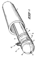
- Fig. 1 shows a pipe liner part 2 of thermoplastic material placed in a pipe 1 which is to be lined, in this example a concrete sewer pipe.
- the pipe liner part illustrated in the deformed state has an essentially C-shaped cross-section, while its original undeformed state is cylindrical.
- the front end of the pipe liner part is provided with a plastic sealing element 3.
- the sealing element 3 comprises a flat plastic plate 5 with two passages 6 and a thick-walled cylindrical pipe part 7 of thermoplastic material welded to the flat plate.
- a hemispherical plastic end cap 8 with a pulling eye 9 is welded to the front side.
- the pulling eye 9 serves for the fastening of a pull-in cable for pulling the pipe liner part into the sewer pipe.
- a device 10 for the connection of a condensation discharge pipe is fitted on the cylindrical pipe part 7.
- the end of the pipe liner part shown in Fig. 1 is then situated in a readily accessible place, for example in a well.
- a heating and pressure medium source is then connected to a passage opening in a shut-off element (not shown) at the other end of the pipe liner part.
- a heating and pressure medium for example steam
- a heating and pressure medium for example steam
- the temperature of the plastic wall of the pipe liner part rises as a result, and a pressure is exerted on the pipe liner part.
- the shape memory of the thermoplastic material of the pipe liner part assisted by the pressure, causes the pipe liner part 2 to return virtually to its original cylindrical cross-section.
- Fig. 2 shows the device 10 when fitted.
- the device 10 comprises a metal feed-through pipe 11 which is inserted through a bore disposed in the wall of the cylindrical part 7.
- a metal sealing ring 12 which penetrates a penetration depth into the plastic wall of the cylindrical pipe part 7 when the connection is being made, is welded to the feed-through pipe 11. This produces a reliable seal, even if the cylindrical part 7 is damaged in the process of being pulled in.
- the sealing ring 12 will be explained in greater detail with reference to Fig. 3.
- Fig. 3 shows in greater detail the embodiment of the metal sealing ring 12 shown in Fig. 2.
- the sealing ring 12 comprises a transverse face 20 in which a bore 21 for the feed-through pipe 11 is provided.
- the sealing ring 12 also has an annular wall 22 forming a penetrating edge which penetrates into the plastic wall.
- the outer face 23 of the annular wall 22 is cylindrical, while the inner face 24 is a part of a conical face running from the free edge inwards.
- the outer face 23 and the inner face 24 in this case form an angle of approximately 10°.
- the annular wall 22 is provided at its free edge with two adjoining bevelled edges 25, 26, which form an angle of 60° between them.
- the device as claimed can be designed in many different ways and can be used in many situations. These are in particular situations in which a temporary connection facility must be provided, since in such a situation the possible weakening of the plastic wall through the metal annular wall penetrating it has little negative effect on the load-bearing capacity of the plastic wall.
- the feed-through pipe could be provided with external screw thread, by means of which the feed-through pipe could be screwed firmly into the plastic wall.
- a reliable seal is then obtained again through the fact that the annular wall connected in a sealing manner to the feed-through pipe cuts into the wall.
- the free edge of the annular wall could also be provided with a sort of toothing, instead of bevelled edges, in order to promote penetration or cutting of the annular wall into the plastic wall.
Landscapes
- Engineering & Computer Science (AREA)
- General Engineering & Computer Science (AREA)
- Mechanical Engineering (AREA)
- Lining Or Joining Of Plastics Or The Like (AREA)
- External Artificial Organs (AREA)
- Separation Using Semi-Permeable Membranes (AREA)
Claims (8)
- Vorrichtung (10) zum Verbinden eines Rohres mit einem Hohlkörper (7) mit einer Kunststoffwand, bestehend aus einem Durchführungsrohr (11), das in eine Öffnung in der Wand des Hohlkörpers eingesetzt werden kann, einem Dichtungsteil (12), das eine Seite zum Drücken gegen die Außenseite der Wand des Hohlkörpers aufweist, und Befestigungsmitteln zum Festlegen des Durchführungsrohrs abdichtend in bezug auf den Hohlkörper, wobei das Dichtungsteil (12) ein aus einem starren Material hergestelltes Teil ist, das mit einer Bohrung (21) versehen ist, durch die das Durchführungsrohr (11) abdichtend vorragen kann, und das an seiner Seite zum Drücken gegen die Außenseite der Wand des Hohlkörpers (7) eine vorstehende Ringwand (22) aufweist, die rund um die Bohrung für das Durchführungsrohr liegt, wobei die ringförmige Wand einen Eindringrand bildet, der in die Kunststoffwand des Hohlkörpers (7) eindringen kann, dadurch gekennzeichnet, daß die Befestigungsmittel eine erste Buchse (14), ein um den Hohlkörper (7) zum Festlegen der ersten Buchse um die in der Wand des Hohlkörpers angeordnete Öffnung anzubringendes Ringelement (13) und eine zweite Buchse (15), die auf die erste Buchse aufzuschrauben ist, umfaßt, wobei die zweite Buchse (15) die Ringwand (22) des innerhalb der ersten Buchse (14) angebrachten Dichtungsteils (12) gegen die Wand des Hohlkörpers drückt.
- Vorrichtung nach Anspruch 1, dadurch gekennzeichnet, daß die Ringwand (22) koaxial mit der Bohrung (21) für das Durchführungsrohr verläuft, die Außenseite (23) der Ringwand im wesentlichen zylindrisch ist und die Innenseite (24) der Ringwand Teil einer von dem freien Rand nach innen laufenden konischen Fläche ist.
- Vorrichtung nach Anspruch 2, dadurch gekennzeichnet, daß die Außenseite (23) und die Innenseite (24) der Ringwand (22) einen Winkel von etwa 10° bilden.
- Vorrichtung nach Anspruch 2 oder 3, dadurch gekennzeichnet, daß die Ringwand (22) an ihrem freien Rand mit zwei aneinandergrenzenden Schrägkanten (25,26) versehen ist.
- Vorrichtung nach einem oder mehreren der vorhergehenden Ansprüche, dadurch gekennzeichnet, daß das Dichtungsteil (12) ein von einer Querseite (20) abgeschlossener Ring ist und die Querseite mit der Bohrung (21) für das Durchführungsrohr versehen ist.
- Vorrichtung nach einem oder mehreren der vorhergehenden Ansprüche, dadurch gekennzeichnet, daß das Dichtungsteil (12) ein Metallteil ist.
- Vorrichtung nach Anspruch 6, dadurch gekennzeichnet, daß das Durchführungsrohr (11) ein Metallteil ist und das Dichtungsteil (12) mit diesem verschweißt ist.
- Vorrichtung nach einem oder mehreren der vorhergehenden Ansprüche, dadurch gekennzeichnet, daß ein Teil des durch die Wand des Hohlkörpers (7) einzusetzenden Durchführungsrohrs (11) mit Rippen und Nuten (16) auf der Außenseite versehen ist.
Applications Claiming Priority (3)
| Application Number | Priority Date | Filing Date | Title |
|---|---|---|---|
| NL9300876A NL9300876A (nl) | 1993-05-21 | 1993-05-21 | Inrichting en werkwijze voor het aansluiten van een buisleiding op een hol lichaam met een kunststof wand. |
| NL9300876 | 1993-05-21 | ||
| PCT/NL1994/000103 WO1994028343A1 (en) | 1993-05-21 | 1994-05-09 | Device and method for connecting a pipe to a hollow body with a plastic wall |
Publications (2)
| Publication Number | Publication Date |
|---|---|
| EP0699285A1 EP0699285A1 (de) | 1996-03-06 |
| EP0699285B1 true EP0699285B1 (de) | 1999-01-20 |
Family
ID=19862425
Family Applications (1)
| Application Number | Title | Priority Date | Filing Date |
|---|---|---|---|
| EP94917186A Expired - Lifetime EP0699285B1 (de) | 1993-05-21 | 1994-05-09 | Vorrichtung zum verbinden eines rohres mit einem kunststoff-hohlkörper |
Country Status (7)
| Country | Link |
|---|---|
| EP (1) | EP0699285B1 (de) |
| AT (1) | ATE176035T1 (de) |
| AU (1) | AU6857894A (de) |
| DE (1) | DE69416120T2 (de) |
| ES (1) | ES2129640T3 (de) |
| NL (1) | NL9300876A (de) |
| WO (1) | WO1994028343A1 (de) |
Family Cites Families (4)
| Publication number | Priority date | Publication date | Assignee | Title |
|---|---|---|---|---|
| DE1178312B (de) * | 1962-10-17 | 1964-09-17 | Friedrich Schardmueller | Insbesondere als Ventilhuelse ausgebildete Durchfuehrung fuer aus duktilem Werkstoffbestehende Behaelter fuer Scheibenwaschanlagen von Kraftfahrzeugen |
| GB1186130A (en) * | 1968-10-02 | 1970-04-02 | Smith Blair Inc | Plastic Pipe Saddle. |
| LU87098A1 (fr) * | 1987-12-31 | 1988-04-05 | Sansson S A | Raccord en t pour tuyauterie |
| US4966397A (en) * | 1989-09-01 | 1990-10-30 | Mckinnon Robert M | Flexible pipe saddle |
-
1993
- 1993-05-21 NL NL9300876A patent/NL9300876A/nl not_active Application Discontinuation
-
1994
- 1994-05-09 WO PCT/NL1994/000103 patent/WO1994028343A1/en not_active Ceased
- 1994-05-09 AU AU68578/94A patent/AU6857894A/en not_active Abandoned
- 1994-05-09 ES ES94917186T patent/ES2129640T3/es not_active Expired - Lifetime
- 1994-05-09 AT AT94917186T patent/ATE176035T1/de not_active IP Right Cessation
- 1994-05-09 DE DE69416120T patent/DE69416120T2/de not_active Expired - Fee Related
- 1994-05-09 EP EP94917186A patent/EP0699285B1/de not_active Expired - Lifetime
Also Published As
| Publication number | Publication date |
|---|---|
| AU6857894A (en) | 1994-12-20 |
| DE69416120D1 (de) | 1999-03-04 |
| NL9300876A (nl) | 1994-12-16 |
| ATE176035T1 (de) | 1999-02-15 |
| EP0699285A1 (de) | 1996-03-06 |
| DE69416120T2 (de) | 1999-06-10 |
| ES2129640T3 (es) | 1999-06-16 |
| WO1994028343A1 (en) | 1994-12-08 |
Similar Documents
| Publication | Publication Date | Title |
|---|---|---|
| US3596933A (en) | Joint for plastic pipe | |
| US4091841A (en) | Pressure plug and method | |
| US3841667A (en) | Non-tapping service line connection fitting | |
| EP1141607B1 (de) | Rohrverbindung | |
| US4907924A (en) | Backward starting locknut | |
| US6481764B1 (en) | Pipe coupling method and apparatus | |
| US4919461A (en) | Pressure cylinder pipe coupling | |
| US3279303A (en) | Two-part expansible fastener | |
| US4256335A (en) | Positive locking terminal bushings for flexible tubing | |
| US4930816A (en) | Joining structures for metal pipes | |
| US3468566A (en) | Conduit coupling | |
| US5947527A (en) | Junction holder for connecting pipes with mechanical joints | |
| EP0485076B1 (de) | Kupplung | |
| EP0836693A1 (de) | Anordnumg mit aufgeweiteten rohr | |
| US5407099A (en) | Device for withdrawing filling material from bags | |
| EP0088507A1 (de) | Zusammengesetzte Rohrverbindung | |
| EP0699285B1 (de) | Vorrichtung zum verbinden eines rohres mit einem kunststoff-hohlkörper | |
| EP0864061B1 (de) | Verbindung für hochdruckleitungen aus metall | |
| US3687492A (en) | Service pipe coupling joint | |
| US3885818A (en) | Insulated coupling joint | |
| GB2282653A (en) | Branch insert | |
| WO1999045307A1 (en) | Branch-pipe ferrule and method of inserting same in a lined mains-pipe | |
| US3408098A (en) | Plastic pipe fittings | |
| US3598428A (en) | Pipe coupling | |
| US5666690A (en) | Condensation line purging device |
Legal Events
| Date | Code | Title | Description |
|---|---|---|---|
| PUAI | Public reference made under article 153(3) epc to a published international application that has entered the european phase |
Free format text: ORIGINAL CODE: 0009012 |
|
| 17P | Request for examination filed |
Effective date: 19951107 |
|
| AK | Designated contracting states |
Kind code of ref document: A1 Designated state(s): AT BE CH DE DK ES FR GB IE IT LI LU NL PT SE |
|
| 17Q | First examination report despatched |
Effective date: 19960307 |
|
| GRAG | Despatch of communication of intention to grant |
Free format text: ORIGINAL CODE: EPIDOS AGRA |
|
| GRAG | Despatch of communication of intention to grant |
Free format text: ORIGINAL CODE: EPIDOS AGRA |
|
| GRAH | Despatch of communication of intention to grant a patent |
Free format text: ORIGINAL CODE: EPIDOS IGRA |
|
| GRAH | Despatch of communication of intention to grant a patent |
Free format text: ORIGINAL CODE: EPIDOS IGRA |
|
| GRAA | (expected) grant |
Free format text: ORIGINAL CODE: 0009210 |
|
| AK | Designated contracting states |
Kind code of ref document: B1 Designated state(s): AT BE CH DE DK ES FR GB IE IT LI LU NL PT SE |
|
| PG25 | Lapsed in a contracting state [announced via postgrant information from national office to epo] |
Ref country code: SE Free format text: THE PATENT HAS BEEN ANNULLED BY A DECISION OF A NATIONAL AUTHORITY Effective date: 19990120 Ref country code: NL Free format text: LAPSE BECAUSE OF FAILURE TO SUBMIT A TRANSLATION OF THE DESCRIPTION OR TO PAY THE FEE WITHIN THE PRESCRIBED TIME-LIMIT Effective date: 19990120 Ref country code: BE Free format text: LAPSE BECAUSE OF FAILURE TO SUBMIT A TRANSLATION OF THE DESCRIPTION OR TO PAY THE FEE WITHIN THE PRESCRIBED TIME-LIMIT Effective date: 19990120 |
|
| REF | Corresponds to: |
Ref document number: 176035 Country of ref document: AT Date of ref document: 19990215 Kind code of ref document: T |
|
| REG | Reference to a national code |
Ref country code: CH Ref legal event code: NV Representative=s name: ISLER & PEDRAZZINI AG Ref country code: CH Ref legal event code: EP |
|
| REG | Reference to a national code |
Ref country code: IE Ref legal event code: FG4D |
|
| ITF | It: translation for a ep patent filed | ||
| REF | Corresponds to: |
Ref document number: 69416120 Country of ref document: DE Date of ref document: 19990304 |
|
| ET | Fr: translation filed | ||
| PG25 | Lapsed in a contracting state [announced via postgrant information from national office to epo] |
Ref country code: PT Free format text: LAPSE BECAUSE OF FAILURE TO SUBMIT A TRANSLATION OF THE DESCRIPTION OR TO PAY THE FEE WITHIN THE PRESCRIBED TIME-LIMIT Effective date: 19990420 Ref country code: DK Free format text: LAPSE BECAUSE OF FAILURE TO SUBMIT A TRANSLATION OF THE DESCRIPTION OR TO PAY THE FEE WITHIN THE PRESCRIBED TIME-LIMIT Effective date: 19990420 |
|
| PG25 | Lapsed in a contracting state [announced via postgrant information from national office to epo] |
Ref country code: DE Free format text: LAPSE BECAUSE OF FAILURE TO SUBMIT A TRANSLATION OF THE DESCRIPTION OR TO PAY THE FEE WITHIN THE PRESCRIBED TIME-LIMIT Effective date: 19990421 |
|
| PG25 | Lapsed in a contracting state [announced via postgrant information from national office to epo] |
Ref country code: LU Free format text: LAPSE BECAUSE OF NON-PAYMENT OF DUE FEES Effective date: 19990509 Ref country code: IE Free format text: LAPSE BECAUSE OF NON-PAYMENT OF DUE FEES Effective date: 19990509 Ref country code: GB Free format text: LAPSE BECAUSE OF NON-PAYMENT OF DUE FEES Effective date: 19990509 |
|
| REG | Reference to a national code |
Ref country code: ES Ref legal event code: FG2A Ref document number: 2129640 Country of ref document: ES Kind code of ref document: T3 |
|
| NLV1 | Nl: lapsed or annulled due to failure to fulfill the requirements of art. 29p and 29m of the patents act | ||
| PLBE | No opposition filed within time limit |
Free format text: ORIGINAL CODE: 0009261 |
|
| STAA | Information on the status of an ep patent application or granted ep patent |
Free format text: STATUS: NO OPPOSITION FILED WITHIN TIME LIMIT |
|
| GBPC | Gb: european patent ceased through non-payment of renewal fee |
Effective date: 19990509 |
|
| 26N | No opposition filed | ||
| PGFP | Annual fee paid to national office [announced via postgrant information from national office to epo] |
Ref country code: ES Payment date: 20020517 Year of fee payment: 9 |
|
| PGFP | Annual fee paid to national office [announced via postgrant information from national office to epo] |
Ref country code: FR Payment date: 20020530 Year of fee payment: 9 Ref country code: CH Payment date: 20020530 Year of fee payment: 9 |
|
| PG25 | Lapsed in a contracting state [announced via postgrant information from national office to epo] |
Ref country code: ES Free format text: LAPSE BECAUSE OF NON-PAYMENT OF DUE FEES Effective date: 20030510 |
|
| PG25 | Lapsed in a contracting state [announced via postgrant information from national office to epo] |
Ref country code: LI Free format text: LAPSE BECAUSE OF NON-PAYMENT OF DUE FEES Effective date: 20030531 Ref country code: CH Free format text: LAPSE BECAUSE OF NON-PAYMENT OF DUE FEES Effective date: 20030531 |
|
| REG | Reference to a national code |
Ref country code: CH Ref legal event code: PL |
|
| PG25 | Lapsed in a contracting state [announced via postgrant information from national office to epo] |
Ref country code: FR Free format text: LAPSE BECAUSE OF NON-PAYMENT OF DUE FEES Effective date: 20040130 |
|
| REG | Reference to a national code |
Ref country code: FR Ref legal event code: ST |
|
| REG | Reference to a national code |
Ref country code: ES Ref legal event code: FD2A Effective date: 20030510 |
|
| PGFP | Annual fee paid to national office [announced via postgrant information from national office to epo] |
Ref country code: DE Payment date: 20080527 Year of fee payment: 15 |
|
| PGFP | Annual fee paid to national office [announced via postgrant information from national office to epo] |
Ref country code: AT Payment date: 20080527 Year of fee payment: 15 |
|
| PGFP | Annual fee paid to national office [announced via postgrant information from national office to epo] |
Ref country code: IT Payment date: 20080529 Year of fee payment: 15 |
|
| PG25 | Lapsed in a contracting state [announced via postgrant information from national office to epo] |
Ref country code: AT Free format text: LAPSE BECAUSE OF NON-PAYMENT OF DUE FEES Effective date: 20090509 |
|
| PG25 | Lapsed in a contracting state [announced via postgrant information from national office to epo] |
Ref country code: DE Free format text: LAPSE BECAUSE OF NON-PAYMENT OF DUE FEES Effective date: 20091201 |
|
| PG25 | Lapsed in a contracting state [announced via postgrant information from national office to epo] |
Ref country code: IT Free format text: LAPSE BECAUSE OF NON-PAYMENT OF DUE FEES Effective date: 20090509 |