EP0698543A1 - Method and device for warning persons in the track area - Google Patents
Method and device for warning persons in the track area Download PDFInfo
- Publication number
- EP0698543A1 EP0698543A1 EP95110152A EP95110152A EP0698543A1 EP 0698543 A1 EP0698543 A1 EP 0698543A1 EP 95110152 A EP95110152 A EP 95110152A EP 95110152 A EP95110152 A EP 95110152A EP 0698543 A1 EP0698543 A1 EP 0698543A1
- Authority
- EP
- European Patent Office
- Prior art keywords
- warning
- station
- train
- stations
- reporting
- Prior art date
- Legal status (The legal status is an assumption and is not a legal conclusion. Google has not performed a legal analysis and makes no representation as to the accuracy of the status listed.)
- Withdrawn
Links
- 238000000034 method Methods 0.000 title claims abstract description 12
- 230000015654 memory Effects 0.000 claims description 42
- 230000011664 signaling Effects 0.000 claims description 34
- 230000005540 biological transmission Effects 0.000 claims description 9
- 230000006870 function Effects 0.000 claims description 7
- 230000002093 peripheral effect Effects 0.000 claims 4
- 230000002441 reversible effect Effects 0.000 description 2
- 238000010276 construction Methods 0.000 description 1
- 238000007796 conventional method Methods 0.000 description 1
- 230000002950 deficient Effects 0.000 description 1
- 230000001939 inductive effect Effects 0.000 description 1
- 238000009434 installation Methods 0.000 description 1
- 230000007257 malfunction Effects 0.000 description 1
- 239000000203 mixture Substances 0.000 description 1
- 238000012544 monitoring process Methods 0.000 description 1
- 230000000737 periodic effect Effects 0.000 description 1
- 230000000750 progressive effect Effects 0.000 description 1
Images


Classifications
-
- B—PERFORMING OPERATIONS; TRANSPORTING
- B61—RAILWAYS
- B61L—GUIDING RAILWAY TRAFFIC; ENSURING THE SAFETY OF RAILWAY TRAFFIC
- B61L23/00—Control, warning or like safety means along the route or between vehicles or trains
- B61L23/06—Control, warning or like safety means along the route or between vehicles or trains for warning men working on the route
Definitions
- the invention relates to a method and a device for warning people in the track area with the features specified in the preamble of claims 1 and 5, respectively.
- Conduct time-division multiplex operation over a high-frequency message channel the stations having an adjustable location address which characterizes the installation location (DE 40 05 354 C2).
- the warning system of this facility is tailored to a single area of application.
- the reporting stations depend on the coordinating warning station. For a second, adjacent use of such a facility - for example for longer construction sites in the track area - a further, complete facility is required: the neighboring reporting stations have comparable, redundant tasks. It is not possible to integrate used reporting stations for other, neighboring warning stations.
- a modular expansion of the warning system that grows with the requirements is very complex because of the inevitable device redundancy.
- a decentralized device for monitoring and controlling track-guided vehicles (DE 24 11 868 A1) is known, according to which signals signaling status coming from detectors AD1 to AD5 are sent to the stations AS1 to AS5 and according to which the Stations are connected to one another via control lines SpL for the purpose of information transmission.
- the Scripture gives no indication that what is known from it decentralized reporting principle to apply to a human warning device.
- the object of the invention is to provide a generic method and a generic device, in which it is possible to warn people in the track area of approaching trains, and a modular, growing with the requirements of the facility is possible.
- the warning device permits economical use both in a single system and in the case of a further modular expansion up to the supply of extensive areas, since the functions of a signaling station can be used for more than one warning station.
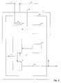
- the reporting station 3 is shown.
- the associated information signaling trains 23 supplied to it arrive in a status memory 53. If appropriate, the status information from the status memory 53 is fed to a preparation 54 and status information signaling signaling new trains is written back into the status memory 53.
- the status information from the status memory 53 is fed to a logic circuit 55 and a first transmitting / receiving circuit 63, which forwards the status information via the information channel 11 to the neighboring reporting station 1, for example. From the latter, the reporting station 3 obtains corresponding status information in the reverse direction from its status memory via the first transceiver 63 and stores it in the memory 57, which is connected to the logic circuit 55.
- the logic circuit 55 derives train assignments and possibly train directions and / or routes for the track area 16 between the signaling stations 1 and 3 in a known manner from the supplied external and signaling the own trains signaling status information. If, for example, the signaling stations 1 and 3 are supplied with signals from direction-sensitive wheel sensors as train-signaling status information 21, 23, the signals from the wheel sensors can be counted in the preparation 54 and the counter reading can be stored in the status memory 53 as new train-signaling status information. Linking circuit 55 finally compares the external and internal counter readings and detects them when the track area 16 is in use. If tension sensors are used instead of wheel sensors, counting and also preparation 54 is not necessary. For example, signaling terms, points or routes can be fed to the signaling stations as information signaling trains.
- the status information can also be transmitted only on one side to an adjacent reporting station or from and to several reporting stations.
- the link circuit 55 contains complex information about train assignments, train directions and / or routes of the trains, which is converted into simple warning signals in a converter 59, which is connected to the link circuit 55, and via a line 75 in a warning memory 61 can be stored. If the occupancy of the track area 16 is detected, a simple warning signal “warning on” could be formed and fed to a second transmitting / receiving circuit 65, which sends this warning signal via the warning channel 13 to the warning station 7 assigned to the track area 16. This could be done from reporting station 1 as well as from reporting station 3.
- the link circuit 55 of the signaling station 3 in correspondence with the signaling station 1 can determine the occupancy of the adjacent track areas 15 and 17 or future assignments of the track areas 15ff and 18 and 18ff, for example from the occupancy of the track area 16 and the direction of the train.
- Corresponding warning information can be specifically passed on via the information channel 11 to those reporting stations that are nearby of the affected track areas so that the latter can deliver the warning information to the warning stations via a short warning channel 13.
- the second transmission / reception circuit 65 is connected to the first transmission / reception circuit 63 via a line 79 or forms a unit with it.
- the warning stations can also be addressed directly via the warning channel 13.
- the reporting stations have a location / address memory 67, which is connected to the transmitting / receiving devices 63, 65 and which allows the reporting stations to be addressed and localized in a known manner.
- the information signaling the complex trains only has to be transmitted between neighboring reporting stations.
- the separate transmission of more extensive but simple warning information reduces the load on the transmission channels.
- signaling-safe operation of the signaling stations is possible independently of the warning stations. This also allows portable and stationary use of the signaling stations as well as any expansion of their arrangement into progressive track areas, whereby a signaling station economically detects at least the adjacent track areas.
- the warning station 7 is shown in FIG. 3 .
- the warning stations have a location / address memory 107 which is connected to a transceiver 103 and which allows the warning stations to be addressed and localized in a known manner.
- the warning information from the signaling stations passes via the warning channel 13 to the transmitting / receiving device 103 in the warning station and from there to a warning memory 105 which, in accordance with the warning information, can send warning signals at its output 117 to internal or external warning means (not shown) in a known manner ( Lengemann, "The automatic warning of rotten” in Eisenbahn Ingenieur Calendar 1990, pp. 333-348).
- operating modes - such as Working on the track, track pedestrian, device in the track - be entered.
- the warning stations can be constructed in completely the same way, can be used or relocated at any point without disturbing the operation of the reporting stations. They are easy to use and economical. By restricting the message to pure warning information, the warning stations can be made portable, small and handy. They are therefore also suitable for fast-moving building blocks in the track area or for track-walkers.
- the train-influencing switching means optionally have a position / address memory 155 which is connected to a transceiver 153 and which allows the train-influencing switching means to be addressed and localized in a known manner.
- the signaling stations indicate signals 85 (FIG. 2) via the message channel 47 or via the transmitting / receiving devices 63.65 (FIG. 2) and the information channel 11, 11d the transceiver 153 in the train-influencing switching means 19 or to a detector 20 (FIG. 1).
- the warning stations indicate when determined in a known manner. impermissible deviations in operation and / or situation-related signals 121 (FIG.
- the transmitting / receiving circuit 153 In the switching device 19 which influences the train, the transmitting / receiving circuit 153 generates control commands 181 from the signals which can inhibit a train in the danger zone. For example, trains can be stopped in the event of malfunctions in stations 3, 7 or in the event of danger due to manual triggering of signals 85, 121.
- the actuators, not shown, which are influenced by the control commands can, for example, be known to be the on-board computer of a train, signals, an INDUSI or an interlocking circuit.
- the message channel can be a radio link.
- the train-influencing switching means 19 can also have a more complex structure and, in a known manner, contain a memory 161 with driving profiles of the normal operating sequence, which are fed to a switching logic 163 which, in a known manner, compares the driving profiles with the train location / direction 175 supplied at their output - and gives driving commands 177 to actuators, not shown, such as signals, switches, brakes, on-board computers at the driving locations and driving areas (DE-PS 1 176 698).
- actuators not shown, such as signals, switches, brakes, on-board computers at the driving locations and driving areas (DE-PS 1 176 698).
- Travel commands can also be routed via the transceiver 153 connected to the switching logic 163 and the information channel 11, 11d or the warning channel 13, 13f.
- the information about the operating mode or task is sent to the transmitting / receiving device 103 (FIG. 3) connected to it, which together with the track-related position information from the position / address memory 107 (FIG. 3) via the warning channel 13, 13f, optionally via at least one reporting station 1, 3, 5 and the information channel 11 - to the transceiver 153 in the train-influencing switching means 19, from which the information reaches a converter 159 via a memory 157 which can issue an acknowledgment 179 via the transmitting / receiving device 153 connected to it in the opposite direction to the transmitting / receiving circuit 103 (FIG. 3) in the warning station 7, 9 at its output 119 (FIG. 3).
- the converter 159 can use the information supplied to it about the track-related position 107 and operating mode 109 of a warning station 7, 9 to take exemplary measures or further measures above, in accordance with the information about the track-related position 107 and operating mode 109, by driving locations and driving areas with train speeds assigned to them forms, converts them into driving profiles and superimposes the usual driving profiles of the normal operating sequence of train traffic in the memory 161 connected to it.
- a warning station 7, 9 is registered by the switching means 19 influencing the train as a standing train or, in the case of a moving warning station, as a slow-moving train, its surroundings being set, for example, as a slow travel point as in tight bends.
- An automatic securing of the danger zone for the people in the track area as well as for the train is thus advantageously integrated into the warning system, the method in the switching means 19 influencing the train being matched to a conventional technique.
- the status information signaling the trains present there can also be sent from the switching logic 163 via the first transceiver 63 (FIG. 2) to the status memory 53 (FIG. 2) connected to it via a line 89 (FIG. 2). 2) in the reporting stations 1, 3, 5 instead of via the inputs 21, 23, 25 of the reporting stations.
- a switching means 19 that influences the train can also be integrated in a signaling station 1, 3, 5 or vice versa.
- the switching means 19 influencing the train can be, for example, the on-board computer of a train or an interlocking circuit.
- reporting stations 1, 3, 5 exchange information not only with their closest neighboring reporting stations, but also with their reporting stations next to one another. If a reporting station fails, the next neighboring reporting stations are then able to take over their function. The failure can be recognized by incorrect information or by the absence thereof, the defective data source being easily localized by a transmission / reception circuit 63, 65 by comparison with the addresses of the other periodic information. If necessary, the faulty data source can be blocked and / or the information channel at the fault location 11a, 11b, 11c, 13a, 13b, 13c can be separated or bridged in a known manner, not shown in detail. The same applies to warning stations 7, 9 with the transmitting / receiving circuit 103 that detects errors and the isolating or bridging point 13d, 13e.
- warning station 7, 9 may take over its tasks by fully or partially integrating a reporting station 1, 3, 5 or vice versa, with similar means or functions only having to be present once.
- the above-mentioned means and functions of the signaling stations 1, 3, 5 can be represented and carried out by the switching means 53 to 67 and / or a computer 51 with its periphery or in a combination thereof.
Landscapes
- Engineering & Computer Science (AREA)
- Mechanical Engineering (AREA)
- Train Traffic Observation, Control, And Security (AREA)
Abstract
Description
Die Erfindung betrifft ein Verfahren und eine Einrichtung zur Warnung von Personen im Gleisbereich mit den im Oberbegriff der Patentansprüche 1 bzw. 5 angegebenen Merkmalen.The invention relates to a method and a device for warning people in the track area with the features specified in the preamble of
Bekannt sind Verfahren und eine Einrichtung zur Warnung von Personen im Gleisbereich vor herannahenden Zügen durch adressierte Warninformationen, die aus Informationen über Fahrstraßen und Zugfahrten in Stellwerken abgeleitet und durch ein entlang der Gleise verlegtes Kabel an Warnstationen geleitet werden. (DE-PS 1 176 698; DE-AS 1 455 379; DE 41 23 960 C1). Es ist sehr aufwendig oder gar unmöglich, nach diesem Verfahren bestehende Stellwerksschaltungen mit Möglichkeiten der Ausgabe von Warninformationen aufzurüsten. Auch bei Neubauten ist der Aufwand bei der Stellwerksschaltung - gemessen an nur wenigen zu warnenden Gleisabschnitten im Stellwerksbereich - unverhältnismäßig hoch. Ein modularer, mit den Erfordernissen wachsender Ausbau des Warnsystems ist nicht möglich, da zunächst die gesamte Stellwerkschaltung aufgerüstet werden muß, bevor auch nur eine Warnstation angesprochen werden kann. Eine umgekehrte Beeinflussung der Stellwerkschaltung durch eine Warnstation ist nicht aufgezeigt.Methods and a device for warning people in the track area against approaching trains by means of addressed warning information are known, which are derived from information about routes and train journeys in signal boxes and are routed to warning stations by a cable laid along the tracks. (DE-PS 1 176 698; DE-AS 1 455 379; DE 41 23 960 C1). It is very complex or even impossible to upgrade existing interlocking circuits with this option with the output of warning information. Even in new buildings, the effort involved in switching signal boxes is disproportionately high - measured by just a few sections of track in the signal box area that have to be warned. A modular expansion of the warning system, which grows with the requirements, is not possible since the entire interlocking circuit must first be upgraded before even a warning station can be addressed. A reverse influence of the signal box circuit by a warning station is not shown.
Bekannt ist ein Verfahren und eine Einrichtung zur Warnung von Personen im Gleisbereich vor herannahenden Zügen durch am Gleis aufgestellte, Züge detektierende, adressierbare Meldestationen, die den Zug signalisierende Statusinformationen an eine im Arbeitsbereich der Personen befindliche, zur Alarmgebung fähige, adressierbare Warnstation im einem erfindungsgemäß organisierten Zeitmultiplexbetrieb über einen hochfrequenten Nachrichtenkanal leiten, wobei die Stationen eine einstellbare, den Aufstellungsort kennzeichnende Ortsadresse aufweisen (DE 40 05 354 C2). Das Warnsystem dieser Einrichtung ist auf jeweils einen einzelnen Einsatzbereich abgestimmt. Die Meldestationen sind von der koordinierenden Warnstation abhängig. Für einen zweiten, benachbarten Einsatz einer solchen Einrichtung - zum Beispiel bei längeren Baustellen im Gleisbereich - ist eine weitere, komplette Einrichtung erforderlich: die benachbarten Meldestationen haben vergleichbare, redundante Aufgaben. Eine Einbindung benutzter Meldestationen für weitere, benachbarte Warnstationen ist nicht möglich. Ein modularer, mit den Erfordernissen wachsender Ausbau des Warnsystems ist wegen der zwangsläufigen Geräteredundanz sehr aufwendig.Known is a method and a device for warning people in the track area of approaching trains by means of addressable signaling stations positioned on the track, which detect trains and address information signaling the train to an addressable warning station located in the work area of the people and capable of alarming in an organized according to the invention Conduct time-division multiplex operation over a high-frequency message channel, the stations having an adjustable location address which characterizes the installation location (DE 40 05 354 C2). The warning system of this facility is tailored to a single area of application. The reporting stations depend on the coordinating warning station. For a second, adjacent use of such a facility - for example for longer construction sites in the track area - a further, complete facility is required: the neighboring reporting stations have comparable, redundant tasks. It is not possible to integrate used reporting stations for other, neighboring warning stations. A modular expansion of the warning system that grows with the requirements is very complex because of the inevitable device redundancy.
Bekannt ist eine dezentrale Einrichtung zur Überwachung und Steuerung spurgeführter Fahrzeuge (DE 24 11 868 A1), gemäß der von Detektoren AD1 bis AD5 herannahende Züge signalisierende Statusinformationen an die Stationen AS1 bis AS5 geleitet werden und gemäß der die Stationen untereinander über Steuerleitungen SpL zum Zwecke der Informationsübertragung verbunden sind. Die Schrift gibt aber keinen Hinweis, das aus ihr bekannte ![]()
![]()
![]()
![]()
![]()
![]()
![]()
![]()
Aufgabe der Erfindung ist es, ein gattungsgemäßes Verfahren und eine gattungsgemäße Einrichtung anzugeben, bei welchen es möglich ist, Personen im Gleisbereich vor herannahen Zügen zu warnen, und wobei ein modularer, mit den Erfordernissen wachsender Ausbau der Einrichtung möglich ist.The object of the invention is to provide a generic method and a generic device, in which it is possible to warn people in the track area of approaching trains, and a modular, growing with the requirements of the facility is possible.
Diese Aufgabe wird erfindungsgemäß bei dem gattungsgemäßen Verfahren bzw. der gattungsgemäßen Einrichtung durch die kennzeichnenden Merkmale des Anspruchs 1 bzw. 5 gelöst.This object is achieved in the generic method or the generic device by the characterizing features of
Die Warneinrichtung gestattet einen wirtschaftlichen Einsatz sowohl bei einer einzelnen Anlage als auch bei weiterem modularen Ausbau bis hin zur Versorgung ausgedehnter Bereiche, da die Funktionen einer Meldestation für mehr als eine Warnstation genutzt werden kann.The warning device permits economical use both in a single system and in the case of a further modular expansion up to the supply of extensive areas, since the functions of a signaling station can be used for more than one warning station.
Weitere vorteilhafte Ausgestaltungen sind in den Unteransprüchen beschrieben. Neben einer Verbesserung der Warnmöglichkeiten bei diesem System sind Maßnahmen genannt, die bei einem modularen Ausbau dieses Warnsystems auch zweckdienliche Funktionen bestehender Einrichtungen wirtschaftlich mit einbeziehen.Further advantageous configurations are described in the subclaims. In addition to improving the warning options in this system, measures are mentioned which, in the case of a modular expansion of this warning system, also economically incorporate useful functions of existing facilities.
Nachfolgend werden Ausführungsbeispiele der Erfindung anhand der Zeichnung näher erläutert. Es zeigt
- Fig. 1 eine Anordnung von Melde- und Warnstationen in Gleisbereichen
- Fig. 2 eine Meldestation
- Fig. 3 eine Warnstation
- Fig. 4 zugbeeinflussende Schaltmittel
- Fig. 1 shows an arrangement of reporting and warning stations in track areas
- Fig. 2 shows a reporting station
- Fig. 3 is a warning station
- Fig. 4 influencing switching means
In Fig. 2 ist die Meldestation 3 dargestellt. Die ihr zugeführten zugeordneten Züge signalisierenden Statusinformationen 23 gelangen in einen Statusspeicher 53. Gegebenenfalls werden die Statusinformationen aus dem Statusspeicher 53 einer Aufbereitung 54 zugeführt und als neue Züge signalisierende Statusinformationen in den Statusspeicher 53 zurück geschrieben. Die Statusinformationen aus dem Statusspeicher 53 werden einer Verknüpfungsschaltung 55 und einer ersten Sende-/Empfangsschaltung 63 zugeleitet, die die Statusinformationen über den Informationskanal 11 zum Beispiel an die benachbarte Meldestation 1 leitet. Von dieser bezieht die Meldestation 3 in umgekehrter Richtung entsprechende Statusinformationen aus deren Statusspeicher über die erste Sende-/Empfangseinrichtung 63 und legt sie in den Speicher 57 ab, der mit der Verknüpfungsschaltung 55 verbunden ist. Die Verknüpfungsschaltung 55 leitet in bekannter Weise aus den zugeführten externen und den eigenen Züge signalisierenden Statusinformationen Zugbelegungen und gegebenenfalls Zugrichtungen und/oder Fahrwege für den Gleisbereich 16 zwischen den Meldestationen 1 und 3 ab. Werden zum Beispiel den Meldestationen 1 und 3 Signale von richtungssensiblen Radsensoren als Züge signalisierende Statusinformationen 21, 23 zugeführt, so können die Signale von den Radsensoren in der Aufbereitung 54 gezählt und der Zählerstand als neue Züge signalisierende Statusinformation in den Statusspeicher 53 gespeichert werden. Durch die Verknüpfungsschaltung 55 werden schließlich der externe und der interne Zählerstand miteinander verglichen und bei Ungleichheit auf Belegung des Gleisbereichs 16 erkannt. Werden Zugsensoren statt Radsensoren eingesetzt, so ist eine Zählung und auch eine Aufbereitung 54 nicht erforderlich. Es können den Meldestationen zum Beispiel auch Signalbegriffe, Weichenstellungen oder Fahrwege als Züge signalisierende Informationen zugeführt sein. Die Statusinformation kann gegebenenfalls auch nur einseitig zu einer benachbarten Meldestation hin oder von und zu mehreren Meldestationen übertragen werden. In der Verknüpfungschaltung 55 stehen je nach Art der zugeführten Statusinformationen komplexe Informationen über Zugbelegungen, Zugrichtungen und/oder Fahrwege der Züge zur Verfügung, die in einem Wandler 59, der mit der Verknüpfungsschaltung 55 verbunden ist, in einfache Warnsignale gewandelt und über eine Leitung 75 in einen Warnspeicher 61 abgelegt werden. Bei Erkennung auf Belegung des Gleisbereichs 16 könnte ein einfaches Warnsignal "Warnung ein" gebildet werden und einer zweiten Sende-/Empfangsschaltung 65 zugeleitet werden, die dieses Warnsignal über den Warnkanal 13 an die dem Gleisbereich 16 zugeordnete Warnstation 7 leitet. Dies könnte sowohl von der Meldestation 1 als auch von der Meldestation 3 geschehen. Diese der Verfügbarkeit nützliche Redundanz wird ohne zusätzlichen Geräteaufwand erreicht. Darüberhinaus kann die Verknüpfungsschaltung 55 der Meldestation 3 bei Korrespondenz mit der Meldestation 1 zum Beispiel aus der Belegung des Gleisbereichs 16 und der Zugrichtung die Belegungen der benachbarten Gleisbereiche 15 und 17 oder zukünftige Belegungen der Gleisbereiche 15ff und 18 sowie 18ff ermitteln. Entsprechende Warninformationen können über den Informationskanal 11 gezielt an jene Meldestationen weitergegeben werden, die sich in der Nähe der betroffenen Gleisbereiche befinden, sodaß diese die Warninformationen an die Warnstationen über einen kurzen Warnkanal 13 abgeben kann. Hierzu ist die zweite Sende-/Empfangsschaltung 65 mit der ersten Sende-/Empfangsschaltung 63 über eine Leitung 79 verbunden oder bildet mit ihr eine Einheit. Die Warnstationen können aber auch unmittelbar über den Warnkanal 13 angesprochen werden. Die Meldestationen verfügen über einen Lage-/Adreßspeicher 67, der mit den Sende-/Empfangseinrichtungen 63, 65 verbunden ist und der es gestattet, die Meldestationen in bekannter Weise gezielt anzusprechen und zu lokalisieren. Die komplexen Züge signalisierende Informationen müssen nur zwischen benachbarten Meldestationen übertragen werden. Die getrennte Übertragung weiterreichender, aber einfacher Warninformationen reduziert die Belastung der Übertragungskanäle. Außerdem ist ein signaltechnisch sicherer Betrieb der Meldestationen unabhängig von den Warnstationen möglich. Dies gestattet auch einen portablen wie stationären Einsatz der Meldestationen sowie eine beliebige Erweiterung deren Anordnung in fortschreitende Gleisbereiche, wobei eine Meldestation in wirtschaftlicher Weise mindestens die angrenzenden Gleisbereiche erfaßt. 2 , the reporting station 3 is shown. The associated
In Fig. 3 ist die Warnstation 7 dargestellt. Die Warnstationen verfügen über einen Lage-/Adreßspeicher 107, der mit einer Sende-/Empfangseinrichtung 103 verbunden ist und der es gestattet, die Warnstationen in bekannter Weise gezielt anzusprechen und zu lokalisieren. Die Warninformationen von den Meldestationen gelangen über den Warnkanal 13 an die Sende-/Empfangseinrichtung 103 in der Warnstation und von dort in einen Warnspeicher 105, der entsprechend der Warninformation in bekannter Weise Warnsignale an seinem Ausgang 117 an nicht dargestellte interne oder externe Warnmittel abgeben kann (Lengemann, "Die automatische Rottenwarnung" in Eisenbahn Ingenieur Kalender 1990, S. 333-348). Im Betriebsartenspeicher 109 können Betriebsarten - wie ![]()
![]()
![]()
![]()
In Fig. 4 sind zugbeeinflussende Schaltmittel 19 dargestellt. Die zugbeeinflussenden Schaltmittel verfügen gegebenenfalls über einen Lage-/Adreßspeicher 155, der mit einer Sende-/Empfangseinrichtung 153 verbunden ist und der es gestattet, die zugbeeinflussenden Schaltmittel in bekannter Weise gezielt anzusprechen und zu lokalisieren. Die Meldestationen geben bei in bekannter Weise ermittelten, unzulässigen Abweichungen im Betrieb und/oder situationsbedingt Signale 85 (Fig. 2) über den Nachrichtenkanal 47 oder über die Sende-/Empfangseinrichtungen 63. 65 (Fig. 2) und den Informationskanal 11, 11d an die Sende-/Empfangseinrichtung 153 im zugbeeinflussenden Schaltmittel 19 oder an einen Melder 20 (Fig. 1) ab. Die Warnstationen geben bei in bekannter Weise ermittelten. unzulässigen Abweichungen im Betrieb und/oder situationsbedingt Signale 121 (Fig. 3) über den Nachrichtenkanal 49 oder über die Sende-/Empfangseinrichtung 103 (Fig. 3) und den Warnkanal 13, 13f an die Sende-/Empfangseinrichtung 153 im zugbeeinflussenden Schaltmittel 19 oder an einen Melder 20 (Fig1) ab. Im zugbeeinflussenden Schaltmittel 19 erzeugt die Sende-/Empfangsschaltung 153 aus den Signalen Stellbefehle 181, die einen Zug im Gefahrenbereich hemmen können. So können zum Beispiel bei Betriebsstörungen der Stationen 3, 7 oder bei Gefahr durch manuelle Auslösung der Signale 85, 121 Züge angehalten werden. Die durch die Stellbefehle beeinflußten, nicht näher dargestellten Stellglieder können zum Beispiel bekannterweise der Bordrechner eines Zuges, Signale, eine INDUSI oder eine Stellwerkschaltung sein. Der Nachrichtenkanal kann eine Funkverbindung sein. 4 influencing switching means 19 are shown. The train-influencing switching means optionally have a position /
Die zugbeeinflussenden Schaltmittel 19 können auch komplexer aufgebaut sein und in bekannter Weise einen Speicher 161 mit Fahrprofilen des normalen Betriebsablaufs enthalten, die einer Schaltlogik 163 zugeführt werden, die in bekannter Weise durch Vergleich der Fahrprofile mit ihr zugeführter Zugorte/-richtung 175 an ihrem Ausgang Stell- und Fahrbefehle 177 an nicht näher dargestellte Stellglieder wie Signale, Weichen, Bremsen, Bordrechner an den Fahrorten und Fahrbereichen abgibt (DE-PS 1 176 698). Die Informationen über Zugorte/-richtung sowie die Stell- undThe train-influencing switching means 19 can also have a more complex structure and, in a known manner, contain a
Fahrbefehle können auch über die mit der Schaltlogik 163 verbundene Sende-/Empfangseinrichtung 153 und den Informationskanal 11, 11d oder den Warnkanal 13, 13f geleitet werden. In einem Betriebsartspeicher 109 (Fig. 3) der Warnstation 7 können nicht näher dargestellt manuell oder voreingestellt Betriebsarten eingegeben werden mit daraus resultierenden Aufgaben für zugbeeinflussende Schaltmittel, zum Beispiel
Vom Betriebsartspeicher 109 (Fig. 3) gelangt die Information über die Betriebsart oder Aufgabe an die mit ihm verbundene Sende-/Empfangseinrichtung 103 (Fig. 3), die diese Information zusammen mit der gleisbezogenen Lageinformation aus dem Lage-/Adreßspeicher 107 (Fig.3) über den Warnkanal 13, 13f gegebenenfalls über mindestens eine Meldestation 1, 3, 5 und den Informationskanal 11 - an die Sende-/Empfangseinrichtung 153 in dem zugbeeinflussenden Schaltmittel 19 weiterleiten, von der die Informationen über einen Speicher 157 an einen Wandler 159 gelangen, der eine Quittierung 179 über die mit ihm verbundene Sende-/Empfangseinrichtung 153 in umgekehrter Richtung an die Sende-/Empfangsschaltung 103 (Fig. 3) in der Warnstation 7, 9 an deren Ausgang 119 (Fig. 3) abgeben kann. Das Ausbleiben der Quittierung ist eine Betriebsstörung, auf die die Warnstation 7, 9 wie bekannt und nicht näher dargestellt mit einer Störwarnung reagieren kann. Der Wandler 159 kann aus den ihm zugeführten Informationen über die gleisbezogene Lage 107 und Betriebsart 109 einer Warnstation 7, 9 oben beispielhaft genannte oder weitere Maßnahmen herbeiführen, indem er entsprechend den Informationen über die gleisbezogene Lage 107 und Betriebsart 109 Fahrorte und Fahrbereiche mit ihnen zugeordneten Zuggeschwindigkeiten bildet, sie in Fahrprofile wandelt und den üblichen Fahrprofilen des normalen Betriebsablaufs des Zugverkehrs in dem mit ihm verbundenen Speicher 161 überlagert. Eine Warnstation 7, 9 wird auf diese Weise von dem zugbeeinflussenden Schaltmittel 19 quasi als stehender oder bei wandernder Warnstation als langsam fahrender Zug registriert, wobei seine Umgebung beispielsweise als Langsamfahrstelle wie bei engen Kurven eingestellt ist. In das Warnsystem wird so vorteilhaft eine automatische Sicherung des Gefahrenbereichs für die Personen im Gleisbereich als auch für den Zug integriert, wobei das Verfahren in den zugbeeinflussenden Schaltmitteln 19 auf eine übliche Technik abgestimmt ist.From the operating mode memory 109 (FIG. 3), the information about the operating mode or task is sent to the transmitting / receiving device 103 (FIG. 3) connected to it, which together with the track-related position information from the position / address memory 107 (FIG. 3) via the
Über den Informationskanal 11, 11d können auch aus der Schaltlogik 163 die dort vorhandenen Züge signalisierenden Statusinformationen über die erste Sende-/Empfangseinrichtung 63 (Fig. 2) an den mit ihr über eine Leitung 89 (Fig.2) verbundenen Statusspeicher 53 (Fig. 2) in den Meldestationen 1, 3, 5 anstatt über die Eingänge 21, 23, 25 der Meldestationen gelangen. Ein zugbeeinflussendes Schaltmittel 19 kann auch in einer Meldestation 1, 3, 5 integriert sein oder umgehrt. Die zugbeeinflussenden Schaltmittel 19 können zum Beispiel der Bordrechner eines Zuges oder eine Stellwerkschaltung sein.Via the
Es ist zweckmäßig, daß Meldestationen 1, 3, 5 nicht nur mit ihren nächst benachbarten, sondern auch mit ihren übernächst benachbarten Meldestationen Informationen austauschen. Bei Ausfall einer Meldestation sind dann die nächst benachbarten Meldestationen in der Lage, deren Funktion zu übernehmen. Der Ausfall ist an fehlerhaften Informationen oder an deren Ausbleiben erkenntlich, wobei durch Vergleich mit den Adressen der übrigen periodischen Informationen die fehlerhafte Datenquelle leicht von einer Sende-/Empfangsschaltung 63, 65 zu lokalisieren ist. Bei Bedarf kann die fehlerhafte Datenquelle gesperrt werden und/oder der Informationskanal an der Fehlerstelle 11a, 11b, 11c, 13a, 13b, 13c in bekannter, nicht näher dargestellten Weise getrennt oder überbrückt werden. Ähnliches gilt für Warnstationen 7, 9 mit der Fehler aufdeckenden Sende-/Empfangsschaltung 103 und der Trenn- oder Überbrückungsstelle 13d, 13e.It is expedient that
Bei speziellen Bedingungen kann es zweckmäßig sein, daß eine Warnstation 7, 9 durch Voll- oder Teilintegration einer Meldestation 1, 3, 5 deren Aufgaben mit übernimmt oder umgekehrt, wobei gleichartige Mittel oder Funktionen nur einmal vorhanden sein müssen.Under special conditions, it may be expedient for a
Die oben genannten Mittel und Funktionen der Meldestationen 1, 3, 5 können durch die genannten Schaltmittel 53 bis 67 und /oder einen Rechner 51 mit seiner Peripherie oder in deren Kombination dargestellt und durchgeführt werden. Gleichartiges gilt für die Schaltmittel 103 bis 109 und einen Rechner 101 mit seiner Peripherie in den Warnstationen 7, 9 sowie für die Schaltmittel 153 bis 163 und einen Rechner 151 mit seiner Peripherie in den zugbeeinflussenden Schaltmitteln 19.The above-mentioned means and functions of the
Claims (10)
dadurch gekennzeichnet,
daß mindestens eine Meldestation (3) die ihr zugeordneten Statusinformationen (23) an mindestens eine benachbarte Meldestation (1, 5) periodisch seriell über mindestens einen in zwischen den Meldestationen (1, 3, 5) liegende Bereiche durch Trennmittel (11a, 11b, 11c, 63) unterteilbaren Informationskanal (11) sendet und/oder die entsprechenden Statusinformationen (21, 25) von mindestens einer benachbarten Meldestation (1, 5) über den Informationskanal (11) empfängt,
daß mindestens eine Meldestation (3) aus den empfangenen Statusinformationen (57) und den eigenen Statusinformationen (53) Zugbelegungen (55) und gegebenenfalls Zugrichtungen und/oder Fahrwege der Züge für den Gleisbereich (16, 17) zwischen den Meldestationen (1, 3, 5) ableitet, und
daß die Meldestation (3) die Zugbelegungen (55) in Warninformationen (59, 61) für die belegten Gleisbereiche (16, 17) zwischen den Meldestationen (1, 3, 5) oder auch angrenzende Gleisbereiche (15, 18) wandelt und an in Gleisbereiche (16, 17) von arbeitenden Personen befindiche, zur Warngebung (105, 117) fähige, adressierbare, diesen Gleisbereichen (16, bzw. 17) zugeordneten Warnstationen (7, bzw. 9) periodisch seriell über mindestens einen in zwischen den Meldestationen (1, 3, 5) und den Warnstationen (7, 9) liegende Bereiche durch Trennmittel (13a, 13b, 13c, 13d, 13e, 63, 65, 103) unterteilbaren Warnkanal (13) leitet.Method for warning people in the track area of approaching trains by addressable signaling stations (1, 3, 5) to which assigned status information (21, 23, 25) is sent to them,
characterized,
that at least one reporting station (3) periodically serializes the status information (23) assigned to it to at least one neighboring reporting station (1, 5) via at least one area between the reporting stations (1, 3, 5) by means of separating means (11a, 11b, 11c , 63) subdividable information channel (11) and / or receive the corresponding status information (21, 25) from at least one neighboring reporting station (1, 5) via the information channel (11),
that at least one reporting station (3) from the received status information (57) and its own status information (53) train assignments (55) and possibly train directions and / or routes of the trains for the track area (16, 17) between the reporting stations (1, 3, 5) derives, and
that the reporting station (3) converts the train assignments (55) into warning information (59, 61) for the occupied track areas (16, 17) between the reporting stations (1, 3, 5) or also adjacent track areas (15, 18) and to in Track areas (16, 17) of working people, capable of issuing warnings (105, 117), addressable warning stations (7 or 9) assigned to these track areas (16 or 17) periodically serially over at least one in between the reporting stations ( 1, 3, 5) and the warning stations (7, 9) areas located by separating means (13a, 13b, 13c, 13d, 13e, 63, 65, 103) divides warning channel (13).
daß mindestens eine Meldestation (3) aus den Statusinformationen (53, 57) die für weitere Gleisbereiche (15ff, 15, 18, 18ff) in Zugrichtung von der Meldestation (3) zu erwartende Zugbelegungen ermittelt,
daß die Meldestation (3) die zu erwartenden Zugbelegungen in Warninformationen für die belegten Gleisbereiche (15ff, 15, 18, 18ff) in Zugrichtung von der Meldestation (3) wandelt und über mindestens eine in Zugrichtung von der Meldestation (3) befindliche Meldestation (1, 5) und/oder direkt an die den belegten Gleisbereichen (15ff, 15, 18, 18ff) zugeordneten Warnstationen leitet.A method according to claim 1, characterized in
that at least one reporting station (3) determines from the status information (53, 57) the train assignments to be expected from the reporting station (3) for other track areas (15ff, 15, 18, 18ff),
that the reporting station (3) converts the expected train assignments into warning information for the occupied track areas (15ff, 15, 18, 18ff) in the train direction from the reporting station (3) and via at least one reporting station (1) located in the train direction from the reporting station (3) , 5) and / or directly to the warning stations assigned to the occupied track areas (15ff, 15, 18, 18ff).
daß die Melde- und/oder Warnstationen (1, 3, 5, 7, 9) oder die Warnstationen (7, 9) über die Meldestationen (1, 3, 5) bei ermittelten, unzulässigen Abweichungen im Betrieb und/oder situationsbedingt Signale (85, 121) über einen Nachrichtenkanal (11, 11d, 11e, 13, 13f, 13g, 47, 49) an Melder (20) abgeben und/oder aufzugbeeinflussende, zur Hemmung (181) einer Zugfahrt fähige Schaltmittel (19) im Gefahren- und Gefahrankündigungsbereich (15ff, 15, 16, 17, 18, 18ff) der Station (1, 3, 5, 7, 9) einwirken.Method according to one of the preceding claims, characterized in that
that the reporting and / or warning stations (1, 3, 5, 7, 9) or the warning stations (7, 9) via the reporting stations (1, 3, 5) in the event of determined, impermissible deviations in operation and / or signals depending on the situation ( 85, 121) via a message channel (11, 11d, 11e, 13, 13f, 13g, 47, 49) to detectors (20) and / or switching means (19) in the danger and hazard announcement area (15ff, 15, 16, 17, 18, 18ff) of the station (1, 3, 5, 7, 9).
daß die Warnstationen (7, 9) Informationen über ihre gleisbezogene Lage (107) und Betriebsart - gegebenenfalls (109) über Meldestationen (1, 3, 5) - an zugbeeinflussende Schaltmittel (19, 177) leiten,
daß die zugbeeinflussenden Schaltmittel (19) entsprechend der gleisbezogenen Lage (107) und Betriebsart (109) einer Warnstation (7, 9) eine oder mehrere folgender Zustände herbeiführen, wobei die Informationen über die gleisbezogene Lage (107) und Betriebsart (109) in Fahrorte und Fahrbereiche mit ihnen zugeordneten Zuggeschwindigkeiten als Fahrprofile (159) gewandelt und den üblichen Fahrprofilen des normalen Betriebsablaufes des Zugverkehrs in einem Speicher (161) überlagert werden, und die Fahrprofile im Speicher (161) in üblicher Weise im Vergleich mit den zugeführten Informationen über Zugorte/-richtung (175) in Stell- und Fahrbefehle (177) an Stellglieder an den Fahrorten und Fahrbereichen über den Informations- oder Warnkanal (11, 13) ausgegeben werden:
that the warning stations (7, 9) pass information on their track-related position (107) and operating mode - optionally (109) via signaling stations (1, 3, 5) - to switching means (19, 177) that influence the train,
that the train-influencing switching means (19) bring about one or more of the following states in accordance with the track-related position (107) and operating mode (109) of a warning station (7, 9), the information about the track-related position (107) and operating mode (109) in driving locations and driving areas with train speeds assigned to them are converted as driving profiles (159) and superimposed on the usual driving profiles of the normal operating sequence of train traffic in a memory (161), and the driving profiles in the memory (161) in a conventional manner in comparison with the information supplied about train locations / direction (175) in positioning and driving commands (177) on actuators at the driving locations and driving areas are output via the information or warning channel (11, 13):
dadurch gekennzeichnet,
daß die Meldestationen (1, 3, 5) einen Rechner (51) mit seiner Peripherie (51 bis 67) aufweisen und der Rechner (51) auf die gesamte Schaltung in der Meldestation (1, 3, 5) einwirken kann, daß die Warnstationen (7, 9) einen Rechner (101) mit seiner Peripherie (101 bis 107) aufweisen und der Rechner (101) auf die gesamte Schaltung in der Warnstation (7, 9) einwirken kann, daß mindestens eine Meldestation (3, 51) die ihr zugeordneten, zugeführten und in einen Statusspeicher (53) gespeicherten Statusinformationen (23) über eine erste Sende-/Empfangseinrichtung (63) an mindestens eine benachbarte Meldestation (1, 5) periodisch seriell über mindestens einen physikalisch durch Trennung einer Verbindung (11a, 11b, 11c) oder logisch durch die erste Sende-/Empfangseinrichtung (63) unterteilbaren Informationskanal (11) sendet und/oder die entsprechenden Statusinformationen (21, 25) von mindestens einer benachbarten Meldestation (1, 5) über den Informationskanal (11) durch die erste Sende-/Empfangsschaltung (63) empfängt und in einen Speicher (57) schreibt,
daß mindestens eine Meldestation (3, 51) aus den empfangenen Statusinformationen im Speicher (57) und den eigenen Statusinformationen im Statusspeicher (53) in einer mit beiden Speichern (53, 57) verbundenen Verknüpfungschaltung (55) Zugbelegungen und gegebenenfalls Zugrichtungen und/oder Fahrwege der Züge für den Gleisbereich (16, 17) zwischen den Meldestationen (1, 3, 5) ableitet, und
daß die Meldestation (3, 51) die Zugbelegungen aus der Verknüpfungsschaltung (55) einem Wandler (59) zuleitet, der die Zugbelegungen in Warninformationen für die belegten Gleisbereiche (16, 17) zwischen den Meldestationen (1, 3, 5) oder auch angrenzende Gleisbereiche (15, 18) wandelt und in einen Warnspeicher (61) speichert, aus dem die Warninformationen von einer zweiten Sende-/Empfangseinrichtung (65) oder die mit ihr über eine Leitung (79) verbundenen oder physikalisch vereinten ersten Sende-/Empfangseinrichtung (63) an in Gleisbereiche (16, 17) von arbeitenden Personen befindliche, zur Warngebung fähige, adressierbare, den Gleisbereichen (16, bzw. 17) zugeordneten Warnstationen (7, bzw. 9) periodisch seriell über mindestens einen physikalisch durch Trennung einer Verbindung (13a, 13b, 13c, 13d, 13e) oder logisch durch die Sende-/Empfangseinrichtung (63, 65) unterteilbaren Warnkanal (13) geleitet werden, wo sie von einer in der Warnstation (7, 9) angeordneten Sende-/Empfangseinrichtung (103), die in der Lage ist den Warnkanal (13) logisch zu trennen, aufgenommen und einem Warnspeicher (105) zugeleitet werden, der Warnsignale (117) intern oder extern abgeben kann.Device for warning people in the track area of approaching trains by addressable signaling stations (1, 3, 5), to which assigned status information (21, 23, 25) is sent to them,
characterized,
that the reporting stations (1, 3, 5) have a computer (51) with its peripherals (51 to 67) and the computer (51) can act on the entire circuit in the reporting station (1, 3, 5), that the warning stations (7, 9) have a computer (101) with its periphery (101 to 107) and the computer (101) can act on the entire circuit in the warning station (7, 9) so that at least one reporting station (3, 51) transmits the status information (23) assigned to it and stored in a status memory (53) via a first one Transmitting / receiving device (63) to at least one adjacent reporting station (1, 5) periodically serially via at least one information channel (11) that can be divided physically by separating a connection (11a, 11b, 11c) or logically by the first transmitting / receiving device (63) ) sends and / or receives the corresponding status information (21, 25) from at least one neighboring reporting station (1, 5) via the information channel (11) through the first transmission / reception circuit (63) and writes it to a memory (57),
that at least one reporting station (3, 51) from the received status information in the memory (57) and the own status information in the status memory (53) in a link circuit (55) connected to both memories (53, 57), train assignments and, if appropriate, train directions and / or routes derives the trains for the track area (16, 17) between the reporting stations (1, 3, 5), and
that the reporting station (3, 51) feeds the train assignments from the logic circuit (55) to a converter (59) which provides the train assignments in warning information for the occupied track areas (16, 17) between the reporting stations (1, 3, 5) or adjacent Track areas (15, 18) converts and stores them in a warning memory (61), from which the warning information from a second transceiver (65) or the first transceiver connected or physically combined via a line (79) ( 63) at addressable warning stations (7 or 9) located in track areas (16, 17) of working persons, capable of issuing warnings, which are assigned to the track areas (16 or 17), periodically serially via at least one physically by disconnecting a connection ( 13a, 13b, 13c, 13d, 13e) or a warning channel (13) which can be subdivided logically by the transceiver (63, 65), where it is transmitted by a transmitting / receiving egg arranged in the warning station (7, 9) Direction (103), which is able to logically separate the warning channel (13), is recorded and fed to a warning memory (105) which can emit warning signals (117) internally or externally.
daß der Rechner (51) in mindestens einer Meldestation (3) durch die Verknüpfungsschaltung (55) aus den Statusinformationen in den Speichern (53, 57) die für weitere Gleisbereiche (15ff, 15, 18, 18ff) in Zugrichtung von der Meldestation (3) zu erwartende Zugbelegungen ermittelt, daß die Meldestation (3, 51) die zu erwartenden Zugbelegungen aus der Verknüpfungsschaltung (55) in Warninformationen für die belegten Gleisbereiche (15ff, 15, 18, 18ff) in Zugrichtung von der Meldestation (3) im Wandler (59) wandelt, in den Warnspeicher (61) ablegt und über die Sende-/Empfangsschaltung (63, 65) und mindestens eine in Zugrichtung befindliche Meldestation (1, 5, 51) durch deren Sende-/Empfangsschaltung (63, 65) über den Informationskanal (11) und/oder direkt an die den belegten Gleisbereichen (15ff, 15, 18, 18ff) zugeordneten Warnstationen durch die Sende-/Empfangseinrichtung (63, 65) über den Warnkanal (13) leitet.Device according to claim 5, characterized in
that the computer (51) in at least one reporting station (3) through the link circuit (55) from the status information in the memories (53, 57) for further track areas (15ff, 15, 18, 18ff) in the direction of pull from the reporting station (3rd ) expected train assignments determines that the reporting station (3, 51) the expected train assignments from the logic circuit (55) in warning information for the occupied track areas (15ff, 15, 18, 18ff) in the direction of the train from the reporting station (3) in the converter ( 59) converts, stores in the warning memory (61) and via the transmitting / receiving circuit (63, 65) and at least one signaling station (1, 5, 51) located in the direction of the train through its transmitting / receiving circuit (63, 65) via the Information channel (11) and / or directly to the warning stations assigned to the occupied track areas (15ff, 15, 18, 18ff) by the transmitting / receiving device (63, 65) via the warning channel (13).
daß zugbeeinflussende Schaltmittel (19) adressierbar sind, einen Rechner (151) mit seiner Peripherie (153, 181) aufweisen und der Rechner (151) auf die gesamte Schaltung der zugbeeinflussenden Schaltmittel (19) einwirken kann,
daß die Rechner (51, 101) in den Melde- und/oder Warnstationen (1, 3, 5, 7, 9) über die Meldestationen (1, 3, 5, 51) bei durch den Rechner (51, 101) ermittelten, unzulässigen Abweichungen im Betrieb und/oder situationsbedingt Signale (85, 121) über einen Nachrichtenkanal (47, 49), oder über die Sende-/Empfangseinrichtungen (63, 65, 103) und über einen Nachrichtenkanal (11, 11d, 11e, 13, 13f, 13g) an Melder (20) abgeben und/oder auf zugbeeinflussende, zur Hemmung einer Zugfahrt fähige Schaltmittel (19) im Gefahren- und Gefahrankündigungsbereich (15ff, 15, 16, 17, 18, 18ff) der Station (1, 3, 5, 7, 9) einwirken, indem die Signale (85, 121) durch eine Sende-/Empfangseinrichtung (153) im zugbeeinflussenden Schaltmittel (19) empfangen und in zugbeeinflussende Stellbefehle (181) gewandelt wird.Device according to one of claims 5 to 6, characterized in that
that train-influencing switching means (19) are addressable, have a computer (151) with its periphery (153, 181) and the computer (151) can act on the entire circuit of the train-influencing switching means (19),
that the computers (51, 101) in the reporting and / or warning stations (1, 3, 5, 7, 9) via the reporting stations (1, 3, 5, 51) determined by the computer (51, 101), impermissible deviations in operation and / or signals (85, 121) depending on the situation via a message channel (47, 49), or via the transmitting / receiving devices (63, 65, 103) and via a message channel (11, 11d, 11e, 13, 13f, 13g) to detectors (20) and / or to switching devices (19) in the danger and hazard warning area (15ff, 15, 16, 17, 18, 18ff) of the station (1, 3, 5, 7, 9) act by the signals (85, 121) being received by a transceiver (153) in the train-influencing switching means (19) and converted into train-influencing control commands (181).
daß die Warnstationen (7, 9) weitere Peripherie des Rechners (101, 109) aufweisen,
daß die zugbeeinflussenden Schaltmittel (19) weitere Peripherie des Rechners (151, 153 bis 163) aufweisen,
daß die Rechner (101) in den Warnstationen (7, 9) Informationen über ihre gleisbezogene Lage aus dem Lage-/Adreßspeicher (107) und ihre Betriebsart aus dem Betriebsartspeicher (109) an die Sende-/Empfangseinrichtung (103) abgeben, die die Informationen über den Warnkanal (13) - gegebenenfalls über mindestens eine Meldestation (1, 3, 5, 51) und den Informationskanal (11) - an die Sende-/Empfangseinrichtung (153) in dem zugbeeinflussenden Schaltmittel (19) weiterleiten, von der die Informationen über einen Speicher (157) an einen Wandler (159) gelangen,
daß der Rechner (151) mit seiner Peripherie (153 bis 163) in den zugbeeinflussenden Schaltmitteln (19) entsprechend der gleisbezogenen Lage (107) und Betriebsart (109) einer Warnstation (7, 9) eine oder mehrere folgender Zustände herbeiführt, wobei der Wandler (159) die Informationen über die gleisbezogene Lage (107) und Betriebsart (109) in Fahrorte und Fahrbereiche mit ihnen zugeordneten Zuggeschwindigkeiten als Fahrprofil wandelt und den üblichen Fahrprofilen des normalen Betriebsablaufs des Zugverkehrs in einem Speicher (161) überlagert, und eine Schaltlogik (163) in üblicher Weise entsprechend den Fahrprofilen im Speicher (161) im Vergleich mit den ihr zugeführten Informationen über Zugorte/-richtung (175) an ihrem Ausgang Stell- und Fahrbefehle (177) an Stellglieder an den Fahrorten und Fahrbereichen über die mit ihr verbundene Sende-/Empfangsschaltung (153) und über den Informations- oder Warnkanal (11, 11d, 13, 13a) abgibt:
that the warning stations (7, 9) have further peripherals of the computer (101, 109),
that the train-influencing switching means (19) have further peripherals of the computer (151, 153 to 163),
that the computers (101) in the warning stations (7, 9) provide information about their track-related location from the location / address memory (107) and their operating mode from the operating mode memory (109) to the transceiver (103), which the Information on the warning channel (13) - possibly via at least one reporting station (1, 3, 5, 51) and the information channel (11) - to the transmitting / receiving device (153) in the train-influencing switching means (19), from which the Information about a memory (157) reaches a converter (159),
that the computer (151) with its peripherals (153 to 163) in the train-influencing switching means (19) according to the track-related position (107) and operating mode (109) of a warning station (7, 9) brings about one or more of the following conditions, the converter (159) converts the information about the track-related position (107) and operating mode (109) into locations and driving areas with train speeds assigned to them as a driving profile and superimposes the usual driving profiles of the normal operating sequence of train traffic in a memory (161), and a switching logic (163 ) in the usual way in accordance with the driving profiles in the memory (161) in comparison with the information supplied to it about train locations / direction (175) at its output, positioning and driving commands (177) to actuators at the driving locations and driving areas via the transmission connected to it - / receiving circuit (153) and via the information or warning channel (11, 11d, 13, 13a) emits:
daß die Rechner (51) mit ihrer Peripherie (51 bis 67) der Meldestationen (1, 3, 5) zumindest Teilaufgaben benachbarter Meldestationen (1, 3, 5) übernehmen können, und
daß die Rechner (51) der Meldestationen (1, 3, 5) bei fehlerhaften oder ausbleibenden Informationen in den Sende-/Empfangsschaltungen (63, 65) die fehlerverursachende Datenquelle (63, 65) der Meldestation (1, 3, 5) bei Überschreiten einer Karenzzeit sperren und/oder den Informationskanal an der Fehlerstelle (11a, 11b, 11c, 13a, 13b, 13c) trennen oder überbrücken.Device according to one of claims 5 to 8, characterized.
that the computers (51) with their periphery (51 to 67) of the reporting stations (1, 3, 5) can take over at least partial tasks of neighboring reporting stations (1, 3, 5), and
that the computer (51) of the reporting stations (1, 3, 5) in the event of incorrect or missing information in the transmitting / receiving circuits (63, 65) the data source (63, 65) of the reporting station (1, 3, 5) causing the error when exceeded block a waiting period and / or separate or bridge the information channel at the fault location (11a, 11b, 11c, 13a, 13b, 13c).
daß der Rechner (101) mit seiner Peripherie (101 bis 109) mindestens einer Warnstation (7, 9) zusätzlich zumindest Teilfunktionen einer Meldestation (1, 3, 5) durch Teilintegration deren Rechner (51) mit seiner Peripherie (51 bis 67) deren Funktion übernimmt oder umgekehrt.Device according to one of claims 5 to 9, characterized in that
that the computer (101) with its periphery (101 to 109) at least one warning station (7, 9) additionally at least partial functions of a reporting station (1, 3, 5) by partially integrating its computer (51) with its periphery (51 to 67) Function takes over or vice versa.
Applications Claiming Priority (2)
| Application Number | Priority Date | Filing Date | Title |
|---|---|---|---|
| DE19944428822 DE4428822C1 (en) | 1994-08-16 | 1994-08-16 | Method and device for warning people in the track area |
| DE4428822 | 1994-08-16 |
Publications (1)
| Publication Number | Publication Date |
|---|---|
| EP0698543A1 true EP0698543A1 (en) | 1996-02-28 |
Family
ID=6525683
Family Applications (1)
| Application Number | Title | Priority Date | Filing Date |
|---|---|---|---|
| EP95110152A Withdrawn EP0698543A1 (en) | 1994-08-16 | 1995-06-29 | Method and device for warning persons in the track area |
Country Status (2)
| Country | Link |
|---|---|
| EP (1) | EP0698543A1 (en) |
| DE (1) | DE4428822C1 (en) |
Cited By (1)
| Publication number | Priority date | Publication date | Assignee | Title |
|---|---|---|---|---|
| DE19602873C1 (en) * | 1996-01-29 | 1997-04-17 | Stein Gmbh | Warning persons in vicinity of railway track of approaching train |
Families Citing this family (1)
| Publication number | Priority date | Publication date | Assignee | Title |
|---|---|---|---|---|
| DE19627681C1 (en) * | 1996-07-10 | 1997-07-24 | Stein Gmbh | Method of warning people in railway platforms |
Citations (5)
| Publication number | Priority date | Publication date | Assignee | Title |
|---|---|---|---|---|
| DE1176698B (en) | 1962-03-30 | 1964-08-27 | Siemens Ag | Train protection system with linear signal transmission between train and track |
| DE1455379A1 (en) | 1964-05-22 | 1969-04-03 | Licentia Gmbh | Device for vehicle spacing on an electronically monitored route |
| DE2411868A1 (en) | 1974-03-12 | 1975-09-18 | Standard Elektrik Lorenz Ag | Superimposed secondary hover-train decentralised monitoring system - with block sector containing vehicle deflectors and chain control devices feeding transmitters |
| DE4005354A1 (en) | 1990-02-21 | 1991-08-22 | Stein Gmbh | METHOD AND DEVICE FOR WARNING PERSONS IN THE TRACK AREA OVER A HIGH-FREQUENCY MESSAGE CHANNEL |
| DE4123960C1 (en) | 1991-07-19 | 1992-08-13 | Stein Gmbh, 8000 Muenchen, De | Warning trackside workers of approaching train - using portable warning devices which receive time division multiplexed information and evaluate respective address codes |
-
1994
- 1994-08-16 DE DE19944428822 patent/DE4428822C1/en not_active Expired - Fee Related
-
1995
- 1995-06-29 EP EP95110152A patent/EP0698543A1/en not_active Withdrawn
Patent Citations (5)
| Publication number | Priority date | Publication date | Assignee | Title |
|---|---|---|---|---|
| DE1176698B (en) | 1962-03-30 | 1964-08-27 | Siemens Ag | Train protection system with linear signal transmission between train and track |
| DE1455379A1 (en) | 1964-05-22 | 1969-04-03 | Licentia Gmbh | Device for vehicle spacing on an electronically monitored route |
| DE2411868A1 (en) | 1974-03-12 | 1975-09-18 | Standard Elektrik Lorenz Ag | Superimposed secondary hover-train decentralised monitoring system - with block sector containing vehicle deflectors and chain control devices feeding transmitters |
| DE4005354A1 (en) | 1990-02-21 | 1991-08-22 | Stein Gmbh | METHOD AND DEVICE FOR WARNING PERSONS IN THE TRACK AREA OVER A HIGH-FREQUENCY MESSAGE CHANNEL |
| DE4123960C1 (en) | 1991-07-19 | 1992-08-13 | Stein Gmbh, 8000 Muenchen, De | Warning trackside workers of approaching train - using portable warning devices which receive time division multiplexed information and evaluate respective address codes |
Cited By (2)
| Publication number | Priority date | Publication date | Assignee | Title |
|---|---|---|---|---|
| DE19602873C1 (en) * | 1996-01-29 | 1997-04-17 | Stein Gmbh | Warning persons in vicinity of railway track of approaching train |
| EP0786392A1 (en) | 1996-01-29 | 1997-07-30 | Stein GmbH | Method and device for warning persons in the track area |
Also Published As
| Publication number | Publication date |
|---|---|
| DE4428822C1 (en) | 1996-04-25 |
Similar Documents
| Publication | Publication Date | Title |
|---|---|---|
| DE69610494T2 (en) | VEHICLE CONTROL SYSTEM | |
| EP1106470B1 (en) | Method for detecting obstacles on railway track sections | |
| EP3247609B1 (en) | Method and device for automatically influencing track-bound vehicles | |
| DE19509696C2 (en) | Procedure for mutual contact between trains and facility for carrying out the procedure | |
| DE4321348C1 (en) | Early warning of hazards for public passenger train transport system - collects error and fault data regarding door closing, temp. etc. in vehicle computer, transmits over short distance to intermediate receiver and/or nearby vehicle, and then to central computer | |
| EP2057056B1 (en) | Method and device for a modular adaptive system for controlling and monitoring railway safety installations | |
| DE19647461C2 (en) | Device for the detection of railway vehicles | |
| WO1999067117A2 (en) | Method for reducing data in railway operation | |
| AT510757B1 (en) | SYSTEM FOR TROUBLE-SAFE AND REDUNDANT TRANSMISSION OF COMPLEX DATA | |
| DE2701925A1 (en) | VEHICLE CONTROL SYSTEM WITH HIGH RELIABILITY | |
| EP0719224B1 (en) | Traffic control system to control operations and traffic flow in rail transport | |
| DE19535856A1 (en) | Computer control system with distributed requirement, non-synchronised region and control computers in different hierarchical planes for railway station signal handling where several trains are awaiting signals for the same track | |
| EP3400161A1 (en) | Track installation and method for operating a track installation | |
| DE10158678B4 (en) | Mobile traffic signal system and method for its control | |
| EP0698543A1 (en) | Method and device for warning persons in the track area | |
| DE102005038386B4 (en) | Device for securing the train sequence in Zugleitbetrieb | |
| DE10336022B4 (en) | Procedure for the flexible allocation of responsibilities of line centers | |
| EP1377492B1 (en) | Traffic control station with data subscriptions and method for operating a traffic control station with data subscriptions | |
| DE102004038205B4 (en) | Method and arrangement for carrying out a driving operation of rail vehicles | |
| DE102006029845A1 (en) | Road sections securing device for rail-bound vehicle assembly, has data-processing system connected with imaging sensor for receiving image data of imaging sensor, where system detects road-sided mechanisms of railway construction | |
| DE19751468A1 (en) | Protecting railway level crossing for road traffic | |
| DE3445115A1 (en) | Arrangement for simplifying and improving safety of running trains | |
| EP1637427B1 (en) | Train safety assembly and method | |
| EP3969346B1 (en) | Display system for a rail vehicle, and method | |
| EP1184252B1 (en) | Clear-track signalling device |
Legal Events
| Date | Code | Title | Description |
|---|---|---|---|
| PUAI | Public reference made under article 153(3) epc to a published international application that has entered the european phase |
Free format text: ORIGINAL CODE: 0009012 |
|
| AK | Designated contracting states |
Kind code of ref document: A1 Designated state(s): AT BE CH DE DK ES FR GB IT LI NL PT SE |
|
| 17P | Request for examination filed |
Effective date: 19960326 |
|
| 17Q | First examination report despatched |
Effective date: 19970213 |
|
| STAA | Information on the status of an ep patent application or granted ep patent |
Free format text: STATUS: THE APPLICATION IS DEEMED TO BE WITHDRAWN |
|
| 18D | Application deemed to be withdrawn |
Effective date: 19970624 |