EP0697802A2 - Verfahren zur Feuchtigkeitsmessung und Steuerung eines Feuchtigkeitssensors in einem Mikrowellenofen - Google Patents
Verfahren zur Feuchtigkeitsmessung und Steuerung eines Feuchtigkeitssensors in einem Mikrowellenofen Download PDFInfo
- Publication number
- EP0697802A2 EP0697802A2 EP95305715A EP95305715A EP0697802A2 EP 0697802 A2 EP0697802 A2 EP 0697802A2 EP 95305715 A EP95305715 A EP 95305715A EP 95305715 A EP95305715 A EP 95305715A EP 0697802 A2 EP0697802 A2 EP 0697802A2
- Authority
- EP
- European Patent Office
- Prior art keywords
- humidity
- section
- sensing
- oscillation
- microwave oven
- Prior art date
- Legal status (The legal status is an assumption and is not a legal conclusion. Google has not performed a legal analysis and makes no representation as to the accuracy of the status listed.)
- Granted
Links
- 238000000034 method Methods 0.000 title claims description 30
- 230000010355 oscillation Effects 0.000 claims abstract description 24
- 230000001965 increasing effect Effects 0.000 claims abstract description 6
- 238000010411 cooking Methods 0.000 claims description 10
- 238000004804 winding Methods 0.000 abstract description 6
- 230000000694 effects Effects 0.000 description 10
- 239000003990 capacitor Substances 0.000 description 4
- 238000010438 heat treatment Methods 0.000 description 4
- 230000003019 stabilising effect Effects 0.000 description 3
- 238000010586 diagram Methods 0.000 description 2
- 238000009434 installation Methods 0.000 description 2
- 238000004519 manufacturing process Methods 0.000 description 2
- 230000002411 adverse Effects 0.000 description 1
- 238000001514 detection method Methods 0.000 description 1
- 230000003028 elevating effect Effects 0.000 description 1
- 238000012827 research and development Methods 0.000 description 1
- 230000006641 stabilisation Effects 0.000 description 1
Images



Classifications
-
- H—ELECTRICITY
- H05—ELECTRIC TECHNIQUES NOT OTHERWISE PROVIDED FOR
- H05B—ELECTRIC HEATING; ELECTRIC LIGHT SOURCES NOT OTHERWISE PROVIDED FOR; CIRCUIT ARRANGEMENTS FOR ELECTRIC LIGHT SOURCES, IN GENERAL
- H05B6/00—Heating by electric, magnetic or electromagnetic fields
- H05B6/64—Heating using microwaves
- H05B6/6447—Method of operation or details of the microwave heating apparatus related to the use of detectors or sensors
- H05B6/6458—Method of operation or details of the microwave heating apparatus related to the use of detectors or sensors using humidity or vapor sensors
-
- F—MECHANICAL ENGINEERING; LIGHTING; HEATING; WEAPONS; BLASTING
- F24—HEATING; RANGES; VENTILATING
- F24C—DOMESTIC STOVES OR RANGES ; DETAILS OF DOMESTIC STOVES OR RANGES, OF GENERAL APPLICATION
- F24C7/00—Stoves or ranges heated by electric energy
- F24C7/08—Arrangement or mounting of control or safety devices
Definitions
- the present invention relates to a method of sensing the humidity of foodstuffs subjected to microwave power in a microwave oven, and to a method for controlling read-time of a humidity sensor in a microwave oven.
- automatic cooking methods used in the microwave oven are classified largely as a program type automatic cooking method and a sensor type automatic cooking method.
- a humidity sensor in the microwave oven senses the humidity value of moisture emitted from foodstuffs heated in the heating chamber, and other sensors monitor other surrounding conditions such as temperature.
- the cooking is controlled by automatic setting of the heating time according to the humidity sensing.
- the humidity values determined generally differ from practical humidity values. This is because, in a microwave oven, food is heated by microwaves generated by a magnetron, and leakage of microwaves, which necessarily happens in the course of heating the food, has an effect on the humidity sensing performed. For example, there is a possibility that microwaves leak and flow through wires and nodes in the circuit and then function as noise to the sensed humidity value.
- One proposal to overcome the problem is to incorporate a plurality of noise-absorbing capacitors in the humidity sensing circuit so as to reduce the effect of the leakage.
- the humidity values are sensed several times and then a mean value of the sensed humidity values is adopted as a resultant sensed humidity value. Whilst this method may bring about some improvement, it cannot remove entirely the bad effect of the leakage of microwaves.
- a method of sensing the humidity of foodstuffs subjected to microwave power in a microwave oven wherein the applied microwave power is oscillated such that each oscillation has one period during which the microwave power is applied and a further period during which the microwave power is interrupted, and wherein the humidity is read during the further periods when the microwave power is interrupted, characterised in that to ensure that the humidity is only read during a further period when the microwave power is interrupted
- said method comprises the steps of sensing the humidity at least twice during each said oscillation of the applied microwave power, comparing the noise levels of the humidity readings sensed, and selecting the humidity reading with the lowest noise level as the value of the humidity reading taken during said further period of each said oscillation.
- the method further comprises the steps of dividing each oscillation of said applied microwave power into two sections, sensing the humidity a plurality of times during each of said sections, increasing a noise count of the humidity readings for each of said sections in dependence upon the difference between the maximum and minimum readings for the respective section, and selecting the readings of the section with the lowest noise count as the readings taken during said further period of each said oscillation.
- the present invention also extends to a method for controlling read-time of an humidity sensor of a microwave oven by which a microwave-rest section can be accurately detected regardless of winding errors or phase errors of wires.
- a method for controlling read-time of a humidity sensor of a microwave oven for cooking food using an oscillation of a magnetron comprising the steps of:
- the humidity sensing circuit of Figure 1 has a humidity sensing section 1 for sensing humidity, an amplifying section 2 for differentially amplifying the output of the humidity sensing section 1, a microcomputer 3 for outputting a control signal for controlling the humidity according to the amplified signal from the amplifying section 2, and an equilibrium control section 4 for controlling the equilibrium of the humidity sensing section 1 according to the humidity control signal from the microcomputer 3.
- the humidity sensing circuit shown in Figure 1 operates as follows.
- the microcomputer 3 sends an humidity control signal having a predetermined value through output terminals PO through P4 and the equilibrium control section 4 and thereby presets the humidity sensing section 1.
- voltages of two nodes a and b of the humidity sensing section 1 are input to the non-inverting terminal and to the inverting terminal respectively of an amplifier OP1 of the amplifying section 2 and are differentially amplified thereby.
- the amplified voltages are input to an humidity value input terminal A/D of the microcomputer 3.
- the input voltages corresponding to the humidity value have analog forms, and are input to an analog/digital converter of the microcomputer 3 and converted thereby to digital values.
- the humidity values differ from the practical humidity value. This is because, in a microwave oven, food is heated by a microwave generated by a magnetron installed in the microwave oven so that leakage of the microwave, which necessarily happens in the course of heating the food, has an effect on the humidity sensing performed by the humidity sensing section 1.
- the control circuit of the microwave oven comprises a high voltage transformer 12 for elevating the voltage of the inputted electric power to a predetermined value, an amplifying section 13 connected to the high voltage transformer 12 so as to amplify the elevated voltage, and a magnetron 14 for generating microwaves utilising the voltage amplified in the amplifying section 13 as a driving power.
- the control circuit also comprises a low voltage transformer 11, and a power supply section 15 for supplying electrical power into a control circuit board using the voltage received from low voltage transformer 11.
- the control circuit board comprises an interrupt signal generating section 16 for generating an interrupt signal according to the power supply from the power supply section 15, an humidity sensing section 17 for sensing the humidity, an amplifying section 18 for amplifying the sensed humidity value, and a microcomputer 19 for generally controlling various parts of the microwave oven in accordance with signals received from the interrupt signal generating section 16 and the amplifying section 18.
- an input power of 110/220V and 60 Hz is applied to the high voltage transformer 12 under the control of a door switch and relay switches for driving the magnetron 14, which switches are not shown.
- a voltage elevated to about 2000V is applied from the secondary windings of the high voltage transformer 12 to the amplifying section 13 having a high voltage condenser H.V.C. and a high voltage diode H.V.D. and is thereby doubled to about 4000V.
- the doubled voltage is applied to the magnetron 14 as a driving voltage so as to make the magnetron 14 oscillate and generate microwaves. Since the electric current is interrupted for half-periods due to the characteristic of the high voltage diode H.V.D. in the amplifying section 13, an oscillation mode and a rest mode alternate corresponding to the frequency of the input power during the whole oscillation.
- input power is supplied by way of the low voltage transformer 11 to the power supply section 15 in the control circuit board.
- the power supply section 15 transforms the input power into a direct current power and then supplies the direct current power to the microcomputer 19, to the humidity sensing section 17, and to other load driving relays (not shown).
- the power supplied to the microcomputer 19 is applied by way of the interrupt signal generating section 16 which applies an outer interrupt signal as a pulse signal by a zero-crossing detection of the frequency of an electric power of the power supply section 15.
- the interrupt signal generating section 16 is used to enable the microcomputer 19 to determine whether the frequency of an electric power is a predetermined frequency such as 50 Hz or 60 Hz, or is used for generating an interrupt signal for a specific object such as a time-count, in a conventional control circuit of a microwave oven.
- FIG. 1 An example of such methods is shown in Figure 1 in which a plurality of noise-absorbing capacitors C1 to C4 are connected to the humidity sensing section 1 and to the amplifying section 2 so as to reduce the effect of the leakage of microwaves.
- the voltage elevated up to about 2000 V by the high voltage transformer 12 is doubled to about 4000 V by the amplifying section 13 having the high voltage condenser H.V.C and the high voltage diode H.V.D. and this voltage is then applied to the magnetron 14 as the main driving voltage of the magnetron.
- the magnetron is driven to have an oscillation mode and an alternate rest mode corresponding to the frequency of input power, such as 50 Hz or 60 Hz, during the whole oscillation of the magnetron since the input power is interrupted during half-periods thereof due to the characteristic of the high voltage diode H.V.D. in the amplifying section 13. Therefore, the humidity value can be read without hindrance by the leakage of microwave in the rest mode at which the oscillation of microwave by the magnetron is instantly interrupted. This solution can be very effective so long as it is accurately determined that the humidity value is read during the rest mode.
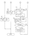
- Figure 3 shows a flow chart for determining the read-time of the humidity sensor of the microwave oven.
- cooking of food in the microwave oven is started according to conditions set by a user (step 100). After the cooking is started, a predetermined time for stabilising the oscillation of the magnetron (about 1-2 seconds) is waited for (step 110).
- the microcomputer 19 checks whether the stabilising time has passed at every predetermined time interval (step 120), and it proceeds to step 130 when the stabilising time has passed.
- step 130 as indicated in Figure 4B, an outer interrupt signal generated by one time at every one period of a frequency of an electric power is divided into two half-periods of time as a first section RT1 and a second section RT2.
- step 140 the routine of the microcomputer 19 is arranged to continually sense whether the outer interrupt signal according to the frequency of the electric power is generated.
- the routine proceeds to step 150.
- the outer interrupt signal is a pulse signal the edge of which is the zero-crossing point of the input power, and the falling edge is recognised as the interrupt.
- step 150 it is decided whether a predetermined read time determining time, which corresponds to about 10 seconds after the stabilisation of the oscillation, has passed.
- the humidity sensing value is read by a predetermined times, such as four times, at regular intervals during the first section (step 160).
- a maximum value RT1 max and a minimum value RT1 min are found out among the values read in step 160, and it is decided whether the difference between the maximum value RT1 max and a minimum value RT1 min is larger than a predetermined noise-determining reference value A (step 170), a noise count in the first section is added one by one when the difference is larger than the value A (step 180).
- the humidity sensing value is read at predetermined times, such as four times, at regular intervals during the second section (step 190).
- a maximum value RT2 max and a minimum value RT2 min are found out among the values read in the second section at step 190, and it is decided whether the difference between the maximum value RT2 max and the minimum value RT2 min is larger than the predetermined noise-determining reference value A (step 200), a noise count in the second section is added one by one when the difference is larger than the value A (step 210).
- Steps 140 through 210 at which an outer interrupt signal generated by one time at every one period of a frequency of an electric power is divided into two half-periods of time and the noise count is added according to the difference between the maximum and the minimum values in each section, are repeated according to the above described process.
- the noise count value RT1 count in the first section RT1 and the noise count value RT2 count in the second section RT2 are compared with each other (step 220).
- the second section RT2 is determined as the humidity sensing read time (step 230).
- the first section RT1 is determined as the humidity sensing read time (step 240).
- the rest section in which no microwave is oscillated is accurately found by determining a half-period of a frequency of an electric power with less noise as the read time, and then the humidity is sensed by reading the humidity sensing value in the read time section decided as above according to the outer interrupt signal after the preset is completed.
- a noise section and a read time section are decided based on the noise-generating frequency, and the humidity sensing value is read only in the read time section. Accordingly, the humidity value can be sensed without being influenced by the leakage of microwave, so that the humidity is accurately sensed. By this means, variances in cooking performance are reduced and so the reliability of the microwave oven is increased.
Landscapes
- Engineering & Computer Science (AREA)
- Physics & Mathematics (AREA)
- Electromagnetism (AREA)
- Chemical & Material Sciences (AREA)
- Combustion & Propulsion (AREA)
- Mechanical Engineering (AREA)
- General Engineering & Computer Science (AREA)
- Electric Ovens (AREA)
- Control Of High-Frequency Heating Circuits (AREA)
- Apparatus For Disinfection Or Sterilisation (AREA)
Applications Claiming Priority (2)
| Application Number | Priority Date | Filing Date | Title |
|---|---|---|---|
| KR1019940020168A KR0128558B1 (ko) | 1994-08-16 | 1994-08-16 | 전자렌지의 습도센서 리드타임 제어방법 |
| KR9420168 | 1994-08-16 |
Publications (3)
| Publication Number | Publication Date |
|---|---|
| EP0697802A2 true EP0697802A2 (de) | 1996-02-21 |
| EP0697802A3 EP0697802A3 (de) | 1996-11-27 |
| EP0697802B1 EP0697802B1 (de) | 2001-01-17 |
Family
ID=19390437
Family Applications (1)
| Application Number | Title | Priority Date | Filing Date |
|---|---|---|---|
| EP95305715A Expired - Lifetime EP0697802B1 (de) | 1994-08-16 | 1995-08-16 | Verfahren zur Feuchtigkeitsmessung und Steuerung eines Feuchtigkeitssensors in einem Mikrowellenofen |
Country Status (6)
| Country | Link |
|---|---|
| US (1) | US5632920A (de) |
| EP (1) | EP0697802B1 (de) |
| JP (1) | JPH08178303A (de) |
| KR (1) | KR0128558B1 (de) |
| CN (1) | CN1088821C (de) |
| DE (1) | DE69519902D1 (de) |
Cited By (1)
| Publication number | Priority date | Publication date | Assignee | Title |
|---|---|---|---|---|
| EP2773163A1 (de) | 2013-03-01 | 2014-09-03 | Lekué, SL | Mikrowellenofen und Verfahren zur automatischen Steuerung des Kochen und/oder Erwärmen von Lebensmitteln in einem solchen Mikrowellenofen. |
Families Citing this family (5)
| Publication number | Priority date | Publication date | Assignee | Title |
|---|---|---|---|---|
| KR100436266B1 (ko) | 2002-04-13 | 2004-06-16 | 삼성전자주식회사 | 전자레인지의 제어 장치 및 방법 |
| CN100359240C (zh) * | 2003-02-21 | 2008-01-02 | 乐金电子(天津)电器有限公司 | 微波炉湿度传感器的电源控制电路 |
| CN100432539C (zh) * | 2003-04-25 | 2008-11-12 | 乐金电子(天津)电器有限公司 | 微波炉及其烹制时间的计算方法 |
| CN102149229B (zh) * | 2010-02-05 | 2016-03-02 | 乐金电子(天津)电器有限公司 | 微波炉内传感器的通信方法与使用该通信方法的微波炉 |
| CN103017217A (zh) * | 2012-12-21 | 2013-04-03 | 敦泰科技有限公司 | 一种微波炉控制方法、控制设备和微波炉 |
Family Cites Families (5)
| Publication number | Priority date | Publication date | Assignee | Title |
|---|---|---|---|---|
| DE2917214A1 (de) * | 1978-04-27 | 1979-11-08 | Amana Refrigeration Inc | Mikrowellenofen |
| CA1200583A (en) * | 1982-03-03 | 1986-02-11 | Shunichi Taguchi | High-frequency heating apparatus with wireless temperature probe |
| JPS61130865A (ja) * | 1984-11-30 | 1986-06-18 | Toshiba Corp | 湿度検出装置 |
| KR960007569Y1 (ko) * | 1990-06-30 | 1996-08-30 | 엘지전자 주식회사 | 전자레인지의 팬모터 회전수 조절회로 |
| KR950011628B1 (ko) * | 1992-11-27 | 1995-10-06 | 엘지전자주식회사 | 전자레인지의 습도 검출장치와 방법 |
-
1994
- 1994-08-16 KR KR1019940020168A patent/KR0128558B1/ko not_active Expired - Fee Related
-
1995
- 1995-08-15 JP JP7208203A patent/JPH08178303A/ja active Pending
- 1995-08-16 US US08/515,966 patent/US5632920A/en not_active Expired - Lifetime
- 1995-08-16 DE DE69519902T patent/DE69519902D1/de not_active Expired - Lifetime
- 1995-08-16 CN CN95116368A patent/CN1088821C/zh not_active Expired - Fee Related
- 1995-08-16 EP EP95305715A patent/EP0697802B1/de not_active Expired - Lifetime
Non-Patent Citations (1)
| Title |
|---|
| None |
Cited By (2)
| Publication number | Priority date | Publication date | Assignee | Title |
|---|---|---|---|---|
| EP2773163A1 (de) | 2013-03-01 | 2014-09-03 | Lekué, SL | Mikrowellenofen und Verfahren zur automatischen Steuerung des Kochen und/oder Erwärmen von Lebensmitteln in einem solchen Mikrowellenofen. |
| WO2014132121A1 (en) | 2013-03-01 | 2014-09-04 | Lekue, Sl | Microwave oven and method for automatically controlling the heating and/or cooking of foods in said microwave oven |
Also Published As
| Publication number | Publication date |
|---|---|
| EP0697802A3 (de) | 1996-11-27 |
| JPH08178303A (ja) | 1996-07-12 |
| KR960008185A (ko) | 1996-03-22 |
| KR0128558B1 (ko) | 1998-04-09 |
| CN1088821C (zh) | 2002-08-07 |
| CN1131259A (zh) | 1996-09-18 |
| US5632920A (en) | 1997-05-27 |
| EP0697802B1 (de) | 2001-01-17 |
| DE69519902D1 (de) | 2001-02-22 |
Similar Documents
| Publication | Publication Date | Title |
|---|---|---|
| US4475024A (en) | Wireless food temperature-sensing assembly | |
| US5349163A (en) | Method of automatically cooking food by detecting the amount of gas or smoke being exhausted from a cooking device during cooking | |
| US5155339A (en) | Automatic cooking method | |
| US7176424B2 (en) | Induction heating cooking apparatus and method for operating the same | |
| EP0697802B1 (de) | Verfahren zur Feuchtigkeitsmessung und Steuerung eines Feuchtigkeitssensors in einem Mikrowellenofen | |
| US5620626A (en) | Method for controlling read-time of a humidity sensor in a microwave oven | |
| US7064305B2 (en) | Apparatus and method for controlling output of magnetron of microwave oven | |
| US4990733A (en) | Microwave oven with improved microwave power control | |
| EP0954204B1 (de) | Magnetronsteuersschaltung bei einem Mikrowellenofen | |
| EP0661909B1 (de) | Automatische Auftauvorrichtung für einen Mikrowellenherd | |
| KR0164233B1 (ko) | 전자레인지 | |
| US5343746A (en) | Humidity sensing apparatus | |
| KR100377722B1 (ko) | 전자레인지의 자동조리제어방법_ | |
| JP3196433B2 (ja) | 電子レンジ | |
| KR930005762B1 (ko) | 전자렌지의 가스센서 불량판정방법 | |
| KR0115086Y1 (ko) | 전자렌지의 가스센서 오 감지 방지회로 | |
| KR19980043794A (ko) | 전자레인지의 온도검출회로 | |
| KR100377720B1 (ko) | 전자레인지의 자동조리제어방법_ | |
| KR100284547B1 (ko) | 전자렌지용 고전압트랜스의 저항부설장치 | |
| JPS61118994A (ja) | 調理器 | |
| JP2001155848A (ja) | 加熱調理器 | |
| KR100377723B1 (ko) | 전자레인지의조리제어방법및장치 | |
| KR950002901Y1 (ko) | 절대습도센서의 신호처리회로 | |
| JPS63133494A (ja) | 調理器 | |
| JPH1187048A (ja) | 高周波加熱装置 |
Legal Events
| Date | Code | Title | Description |
|---|---|---|---|
| PUAI | Public reference made under article 153(3) epc to a published international application that has entered the european phase |
Free format text: ORIGINAL CODE: 0009012 |
|
| AK | Designated contracting states |
Kind code of ref document: A2 Designated state(s): DE FR GB NL |
|
| PUAL | Search report despatched |
Free format text: ORIGINAL CODE: 0009013 |
|
| AK | Designated contracting states |
Kind code of ref document: A3 Designated state(s): DE FR GB NL |
|
| 17P | Request for examination filed |
Effective date: 19970520 |
|
| 17Q | First examination report despatched |
Effective date: 19980505 |
|
| GRAG | Despatch of communication of intention to grant |
Free format text: ORIGINAL CODE: EPIDOS AGRA |
|
| 17Q | First examination report despatched |
Effective date: 19980505 |
|
| GRAG | Despatch of communication of intention to grant |
Free format text: ORIGINAL CODE: EPIDOS AGRA |
|
| GRAH | Despatch of communication of intention to grant a patent |
Free format text: ORIGINAL CODE: EPIDOS IGRA |
|
| GRAH | Despatch of communication of intention to grant a patent |
Free format text: ORIGINAL CODE: EPIDOS IGRA |
|
| GRAA | (expected) grant |
Free format text: ORIGINAL CODE: 0009210 |
|
| AK | Designated contracting states |
Kind code of ref document: B1 Designated state(s): DE FR GB NL |
|
| PG25 | Lapsed in a contracting state [announced via postgrant information from national office to epo] |
Ref country code: NL Free format text: LAPSE BECAUSE OF FAILURE TO SUBMIT A TRANSLATION OF THE DESCRIPTION OR TO PAY THE FEE WITHIN THE PRESCRIBED TIME-LIMIT Effective date: 20010117 Ref country code: FR Free format text: LAPSE BECAUSE OF FAILURE TO SUBMIT A TRANSLATION OF THE DESCRIPTION OR TO PAY THE FEE WITHIN THE PRESCRIBED TIME-LIMIT Effective date: 20010117 |
|
| REF | Corresponds to: |
Ref document number: 69519902 Country of ref document: DE Date of ref document: 20010222 |
|
| PG25 | Lapsed in a contracting state [announced via postgrant information from national office to epo] |
Ref country code: DE Free format text: LAPSE BECAUSE OF FAILURE TO SUBMIT A TRANSLATION OF THE DESCRIPTION OR TO PAY THE FEE WITHIN THE PRESCRIBED TIME-LIMIT Effective date: 20010418 |
|
| EN | Fr: translation not filed | ||
| NLV1 | Nl: lapsed or annulled due to failure to fulfill the requirements of art. 29p and 29m of the patents act | ||
| PLBE | No opposition filed within time limit |
Free format text: ORIGINAL CODE: 0009261 |
|
| STAA | Information on the status of an ep patent application or granted ep patent |
Free format text: STATUS: NO OPPOSITION FILED WITHIN TIME LIMIT |
|
| REG | Reference to a national code |
Ref country code: GB Ref legal event code: IF02 |
|
| 26N | No opposition filed | ||
| REG | Reference to a national code |
Ref country code: GB Ref legal event code: 732E |
|
| PGFP | Annual fee paid to national office [announced via postgrant information from national office to epo] |
Ref country code: GB Payment date: 20090812 Year of fee payment: 15 |
|
| GBPC | Gb: european patent ceased through non-payment of renewal fee |
Effective date: 20100816 |
|
| PG25 | Lapsed in a contracting state [announced via postgrant information from national office to epo] |
Ref country code: GB Free format text: LAPSE BECAUSE OF NON-PAYMENT OF DUE FEES Effective date: 20100816 |