EP0697792A2 - Recording digital video signals - Google Patents
Recording digital video signals Download PDFInfo
- Publication number
- EP0697792A2 EP0697792A2 EP19950305784 EP95305784A EP0697792A2 EP 0697792 A2 EP0697792 A2 EP 0697792A2 EP 19950305784 EP19950305784 EP 19950305784 EP 95305784 A EP95305784 A EP 95305784A EP 0697792 A2 EP0697792 A2 EP 0697792A2
- Authority
- EP
- European Patent Office
- Prior art keywords
- macro
- quantization step
- quantization
- blocks
- circuit
- Prior art date
- Legal status (The legal status is an assumption and is not a legal conclusion. Google has not performed a legal analysis and makes no representation as to the accuracy of the status listed.)
- Granted
Links
Images


Classifications
-
- H—ELECTRICITY
- H04—ELECTRIC COMMUNICATION TECHNIQUE
- H04N—PICTORIAL COMMUNICATION, e.g. TELEVISION
- H04N5/00—Details of television systems
- H04N5/76—Television signal recording
- H04N5/91—Television signal processing therefor
- H04N5/917—Television signal processing therefor for bandwidth reduction
-
- H—ELECTRICITY
- H04—ELECTRIC COMMUNICATION TECHNIQUE
- H04N—PICTORIAL COMMUNICATION, e.g. TELEVISION
- H04N9/00—Details of colour television systems
- H04N9/79—Processing of colour television signals in connection with recording
- H04N9/80—Transformation of the television signal for recording, e.g. modulation, frequency changing; Inverse transformation for playback
- H04N9/804—Transformation of the television signal for recording, e.g. modulation, frequency changing; Inverse transformation for playback involving pulse code modulation of the colour picture signal components
- H04N9/8042—Transformation of the television signal for recording, e.g. modulation, frequency changing; Inverse transformation for playback involving pulse code modulation of the colour picture signal components involving data reduction
- H04N9/8047—Transformation of the television signal for recording, e.g. modulation, frequency changing; Inverse transformation for playback involving pulse code modulation of the colour picture signal components involving data reduction using transform coding
-
- H—ELECTRICITY
- H04—ELECTRIC COMMUNICATION TECHNIQUE
- H04N—PICTORIAL COMMUNICATION, e.g. TELEVISION
- H04N19/00—Methods or arrangements for coding, decoding, compressing or decompressing digital video signals
- H04N19/10—Methods or arrangements for coding, decoding, compressing or decompressing digital video signals using adaptive coding
- H04N19/102—Methods or arrangements for coding, decoding, compressing or decompressing digital video signals using adaptive coding characterised by the element, parameter or selection affected or controlled by the adaptive coding
- H04N19/124—Quantisation
- H04N19/126—Details of normalisation or weighting functions, e.g. normalisation matrices or variable uniform quantisers
-
- H—ELECTRICITY
- H04—ELECTRIC COMMUNICATION TECHNIQUE
- H04N—PICTORIAL COMMUNICATION, e.g. TELEVISION
- H04N19/00—Methods or arrangements for coding, decoding, compressing or decompressing digital video signals
- H04N19/10—Methods or arrangements for coding, decoding, compressing or decompressing digital video signals using adaptive coding
- H04N19/134—Methods or arrangements for coding, decoding, compressing or decompressing digital video signals using adaptive coding characterised by the element, parameter or criterion affecting or controlling the adaptive coding
- H04N19/146—Data rate or code amount at the encoder output
- H04N19/149—Data rate or code amount at the encoder output by estimating the code amount by means of a model, e.g. mathematical model or statistical model
-
- H—ELECTRICITY
- H04—ELECTRIC COMMUNICATION TECHNIQUE
- H04N—PICTORIAL COMMUNICATION, e.g. TELEVISION
- H04N19/00—Methods or arrangements for coding, decoding, compressing or decompressing digital video signals
- H04N19/10—Methods or arrangements for coding, decoding, compressing or decompressing digital video signals using adaptive coding
- H04N19/169—Methods or arrangements for coding, decoding, compressing or decompressing digital video signals using adaptive coding characterised by the coding unit, i.e. the structural portion or semantic portion of the video signal being the object or the subject of the adaptive coding
- H04N19/17—Methods or arrangements for coding, decoding, compressing or decompressing digital video signals using adaptive coding characterised by the coding unit, i.e. the structural portion or semantic portion of the video signal being the object or the subject of the adaptive coding the unit being an image region, e.g. an object
- H04N19/176—Methods or arrangements for coding, decoding, compressing or decompressing digital video signals using adaptive coding characterised by the coding unit, i.e. the structural portion or semantic portion of the video signal being the object or the subject of the adaptive coding the unit being an image region, e.g. an object the region being a block, e.g. a macroblock
-
- H—ELECTRICITY
- H04—ELECTRIC COMMUNICATION TECHNIQUE
- H04N—PICTORIAL COMMUNICATION, e.g. TELEVISION
- H04N19/00—Methods or arrangements for coding, decoding, compressing or decompressing digital video signals
- H04N19/10—Methods or arrangements for coding, decoding, compressing or decompressing digital video signals using adaptive coding
- H04N19/189—Methods or arrangements for coding, decoding, compressing or decompressing digital video signals using adaptive coding characterised by the adaptation method, adaptation tool or adaptation type used for the adaptive coding
- H04N19/192—Methods or arrangements for coding, decoding, compressing or decompressing digital video signals using adaptive coding characterised by the adaptation method, adaptation tool or adaptation type used for the adaptive coding the adaptation method, adaptation tool or adaptation type being iterative or recursive
-
- H—ELECTRICITY
- H04—ELECTRIC COMMUNICATION TECHNIQUE
- H04N—PICTORIAL COMMUNICATION, e.g. TELEVISION
- H04N19/00—Methods or arrangements for coding, decoding, compressing or decompressing digital video signals
- H04N19/60—Methods or arrangements for coding, decoding, compressing or decompressing digital video signals using transform coding
-
- H—ELECTRICITY
- H04—ELECTRIC COMMUNICATION TECHNIQUE
- H04N—PICTORIAL COMMUNICATION, e.g. TELEVISION
- H04N19/00—Methods or arrangements for coding, decoding, compressing or decompressing digital video signals
- H04N19/85—Methods or arrangements for coding, decoding, compressing or decompressing digital video signals using pre-processing or post-processing specially adapted for video compression
- H04N19/88—Methods or arrangements for coding, decoding, compressing or decompressing digital video signals using pre-processing or post-processing specially adapted for video compression involving rearrangement of data among different coding units, e.g. shuffling, interleaving, scrambling or permutation of pixel data or permutation of transform coefficient data among different blocks
-
- H—ELECTRICITY
- H04—ELECTRIC COMMUNICATION TECHNIQUE
- H04N—PICTORIAL COMMUNICATION, e.g. TELEVISION
- H04N7/00—Television systems
- H04N7/24—Systems for the transmission of television signals using pulse code modulation
- H04N7/52—Systems for transmission of a pulse code modulated video signal with one or more other pulse code modulated signals, e.g. an audio signal or a synchronizing signal
- H04N7/54—Systems for transmission of a pulse code modulated video signal with one or more other pulse code modulated signals, e.g. an audio signal or a synchronizing signal the signals being synchronous
-
- H—ELECTRICITY
- H04—ELECTRIC COMMUNICATION TECHNIQUE
- H04N—PICTORIAL COMMUNICATION, e.g. TELEVISION
- H04N19/00—Methods or arrangements for coding, decoding, compressing or decompressing digital video signals
- H04N19/10—Methods or arrangements for coding, decoding, compressing or decompressing digital video signals using adaptive coding
- H04N19/134—Methods or arrangements for coding, decoding, compressing or decompressing digital video signals using adaptive coding characterised by the element, parameter or criterion affecting or controlling the adaptive coding
- H04N19/146—Data rate or code amount at the encoder output
Definitions
- This invention relates to methods of and apparatus for processing digital video signals, in which the digital video signals, which may for instance be in the form of DCT coefficients, obtained by, for example, a discrete cosine transform operation, are quantized and compressed, for example for recording on a recording medium. More particularly, but not exclusively, the invention relates to methods and apparatus for recording digital video signals which advantageously may be employed for a digital video tape recorder for recording/reproducing video signals for a high definition television system.
- the digital VTR may be set to a mode for recording video signals of the current television system, such as the NTSC system, referred to herein as a SD mode, or to a mode for recording video signals of the high definition television system, referred to herein as a HD mode.
- a mode for recording video signals of the current television system such as the NTSC system, referred to herein as a SD mode
- HD mode a mode for recording video signals of the high definition television system
- the video signals are compressed and recorded as digital video signals of approximately 25 Mbps and as digital video signals of approximately 50 Mbps for the SD mode and for the HD mode, respectively.
- the video signal, converted into the digital signals are divided into blocks of a suitable size, such as DCT blocks of 8x8 pixels.
- DCT blocks of 8x8 pixels Six DCT blocks of luminance data, one DCT block of R-Y data and one DCT block of B-Y data, totalling eight blocks, make up one macro-block.
- a plurality of macro-blocks are shuffled, that is, five macro-blocks at discrete positions on a picture are assembled into one unit.
- Two-dimensional DCT is then carried out on the unit basis, with the block size of 8 x 8.
- Data obtained by the two-dimensional DCT that is DCT coefficients, are stored in a memory on the unit basis.
- the total number of codes are estimated on the unit basis and the quantization steps are determined which will give the total number of codes which is smaller than a pre-set value.
- the DCT coefficients are then quantized on the unit basis, with the thus determined quantization step, and variable length encoded by the Huffman code.
- the resulting quantized units are accommodated in video segments by way of framing.
- the codes thus quantized and accommodated in a fixed bit length range on the unit basis, that is on the video segment basis, are re-arrayed in a sequence in which the macro-blocks are arrayed in continuous sequence on the picture, so as to be recorded at pre-set positions on the magnetic tape.
- a sole quantization step is accorded to each video segment and all DCT coefficients in each video segment are quantized with the thus accorded quantization step. That is, the same quantization step is accorded to plural macro-blocks.
- the quantization step is determined so that the total number of quantized codes on setting the fixed bit length on the video segment basis will be less than a pre-set value.
- the actual mount of quantized codes on fixed length coding becomes significantly smaller than the above-mentioned pre-set value, so that efficient encoding cannot be achieved.
- the degree of quantization for the respective blocks becomes coarse with the result that the picture cannot be improved in quality.
- a method for recording quantized and encoded digital video signals comprising the steps of determining a quantization step in terms of a video segment made up of plural macro-blocks as a unit so that the quantity of quantized data is less than a pre-set data quantity, determining a quantization step in terms of the macro-blocks as a unit so that the quantity of quantized data is less than the pre-set data quantity, and quantizing the digital video signals with the determined quantization steps.
- the quantization step is determined on the macro-block basis by giving priority to the macro-block which is located at a mid portion of a picture.
- an apparatus for recording quantized and encoded digital video signals comprising first quantization step decision means for determining a quantization step in terms of a video segment made up of plural macro-blocks as a unit so that the quantity of quantized data is less than a pre-set data quantity, second quantization step decision means for determining a quantization step in terms of the macro-blocks as a unit so that the quantity of quantized data is less than the pre-set data quantity, and quantization means for quantizing the digital video signals with the quantization steps determined by the first quantization step decision means and the second quantization step decision means.
- the quantization step is determined on the macro-block basis by giving priority to the macro-block which is located at a mid portion of a picture.
- a quantization step is determined in terms of the macro-blocks as a unit so that the quantity of quantized data is less than a pre-set data quantity.
- a quantization step is also determined in terms of the macro-blocks as a unit so that the quantity of quantized data is less than the pre-set data quantity.
- the digital video signals are quantized with the quantization steps thus determined and the quantized and encoded digital video signals are recorded on a recording medium. This enables the degree of quantization to be refined in a range of a pre-set data quantity of the quantized data to render it possible to make effective utilization of redundant bits, thus assuring efficient encoding and improved picture quality.
- the quantization step is determined on the macro-block basis by giving priority to the macro-block which is located at a mid portion of a picture, the picture of satisfactory quality can be obtained in a mid portion of the picture which may be noticed most readily by the eye, thus further assuring improved picture quality.
- the first quantization step decision unit determines a quantization step in terms of a video segment made up of plural macro-blocks as a unit so that the quantity of quantized data is less than a pre-set data quantity
- the second quantization unit decision unit determines a quantization step in terms of the macro-blocks as a unit so that the quantity of quantized data is less than the pre-set data quantity.
- the quantization unit quantizes the digital video signals with the quantization steps determined by the first quantization step decision unit and the second quantization step decision unit. This enables the degree of quantization to be refined in a range of a pre-set data quantity of quantized data to render it possible to make effective utilization of redundant bits, thus assuring efficient encoding and improved picture quality.
- the quantization step is determined on the macro-block basis by giving priority to the macro-block which is located at a mid portion of a picture, the picture of satisfactory picture quality can be obtained in a mid portion of the picture which may be noticed most readily by the eye, thus further assuring improved picture quality.
- the embodiment of the present invention described below provides a method and apparatus for digital video signals in which the quantization step determined on the video segment basis is shifted on the macro-block basis so that the quantization steps will be determined on the macro-block basis for enabling efficient encoding and improving the picture quality.
- Fig.1 is a block diagram showing an arrangement of an encoder of a recording apparatus for digital video signals for carrying out a digital video signal recording method according to an embodiment of the present invention.
- Fig.2 illustrates a shuffling operation for five macro-blocks.
- Fig.3 illustrates the order of scanning in a super-block in the shuffling operation.
- Fig.4 illustrates the state of fixed length encoded and quantized macro-blocks when quantization steps are determined by a first quantization step decision means of the encoder.
- Fig.5 illustrate the state of fixed length encoded and quantized macro-blocks when the quantization steps are determined by a second quantization step decision means of the encoder.
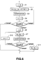
- Fig.6 is a flow chart for illustrating the process of determining the quantization step by the first quantization step decision means and the second quantization step decision means.
- Fig.7 illustrates the construction of a video segment.
- Fig.8 illustrates the construction of each sync block of the above-mentioned video segment.
- Fig.9 illustrates the construction of the discrimination code of the sync block.
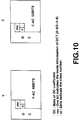
- Fig.10 illustrates the construction of DCT blocks of the luminance data, R-Y data and R-B data in the sync block.
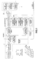
- the digital video signal recording method is carried out by a recording method for digital video signals having an encoder configured as shown in Fig.1.
- the encoder has a transform unit 1 for processing macro-blocks of the digital video signals with discrete cosine transform (DCT), an encoding unit 2 and a framing unit 3.
- the encoding unit 2 is configured for quantizing DCT coefficients resulting from DCT with a quantization step determined on the macro-block basis by shifting the quantization step determined on the basis of units each made up of plural macro-blocks.
- the transform unit 1 includes a blocking circuit 11 for dividing the digital video signals into 8x8-pixel blocks, a shuffling circuit 12 for effecting macro-block based shuffling, a motion detection circuit 13, a DCT circuit 14 for effecting two-dimensional DCT with the block size of 8x8, a picture memory 15 and an activity detection circuit 16.
- the encoding unit 2 includes a data quantity estimating circuit 21, a Huffman table 22 for effecting variable length coding, a first quantization step decision circuit 23, a second quantization step decision circuit 24, a quantization circuit 25 and a variable length encoding circuit 26.
- the data quantity estimating circuit calculates the data quantity following quantization
- the first quantization step decision circuit 23 determines the quantization step within a range of a pre-set quantity of quantized data in terms of units each consisting of five macro-blocks.
- the second quantization step decision circuit 24 determines the quantization steps within a range of a pre-set quantity of quantized data in terms of macro-units.
- the quantization circuit 25 effects quantization with quantization steps determined by the first quantization step decision circuit 23 and the second quantization step decision circuit 24.
- the variable length encoding circuit 26 variable length encodes the quantized data from the quantization circuit 25.
- the framing circuit 3 has a deshuffling circuit 31, a parity appending circuit 32 and a channel encoding circuit 33.
- the blocking circuit 11 fed with input digital video data, forms DCT blocks, each consisting of an array of 8x8 pixels, totalling 64 pixels, from luminance data Y, data C R and data C B of the same domain.
- the data C R is the color difference data R-Y
- the data C B is the color difference data B-Y. That is, the blocking circuit forms one macro-block from six DCT blocks of luminance data Y, one DCT block of color difference data C R and one DCT block of color difference data C B , and outputs the resulting macro-block.
- the shuffling circuit 12 effects pre-set macro-block based shuffling on the digital video signals macro-blocked by the blocking circuit 11. After shuffling the macro-blocks, each one macro-block is taken out from each of super macro-blocks S1 to S5 which are separated from one another on a picture P and which are made up each of 27 macro-blocks, as shown in Fig.2. Thus, five macro-blocks M1 to M5 are collected to form a sole fixed length forming unit, which is outputted.
- the fixed length forming unit is referred to herein simply as a unit.
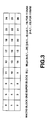
- n is the number of lines
- the macro-blocks of each of the super macro-blocks S1 to S5 are scanned in the sequence of the macro-block 0, macro-block 1, macro-block 2, ...macro-block 26, as shown in Fig.3.
- the motion detection circuit 13 effects motion detection in terms of five macro-blocks formed into one unit by the shuffling circuit 12.
- the results of motion detection are fed to the DCT circuit 14, while being outputted as the subsidiary information to e.g., a reproducing system, not shown.
- the DCT circuit 14 performs DCT on picture data devoid of motion, in terms DCT blocks each made of 8x8 pixels, based upon the results of detection by the motion detection circuit 13. On the other hand, the DCT circuit 14 performs DCT on sum data or differential data between fields of picture data exhibiting motion in terms of 2 DCT blocks each made up of 8x4 pixels. The DCT circuit 14 outputs dc components to the framing unit 3, while outputting ac components to the picture memory 15.
- the picture memory 15 transiently stores the ac components resulting from DCT by the DCT circuit 14 in terms of units.
- the activity detection unit 16 detects, as the information specifying the activity of a picture, the maximum value of the ac components resulting from DCT by the DCT circuit 14 of the one-unit data stored in the picture memory 15 and outputs the results of detection as the subsidiary information to e.g., a reproducing system, not shown.
- the data quantity estimation circuit 21 is responsive to the results of unit-based activity detection by the activity detection circuit 12 to classify the ac components stored in the picture memory 15 in association with the degree of quantization at the time of quantization.
- the first quantization step decision circuit 23 calculates an optimum quantization step for the luminance data Y, color difference data C R and the color difference data C B , based upon the information of classification from the estimation circuit 21 and the codes in the Huffman table 22.
- the second quantization step decision circuit 24 determines, from the quantization step determined on the unit basis by the first quantization step decision circuit 23, the quantization step for each of the five macro-blocks in the unit within a range lesser than targeted fixed bit length.
- the quantization step is determined on the macro-block basis so that priority is given a macro-block among the five macro-blocks which is located closer the center of the picture.
- the quantization circuit 25 quantizes the one-unit data (ac components) stored in the picture memory 15 at a quantization step as determined by the second quantization step decision circuit 24, and transmits the resulting quantization data to the variable length encoding circuit 26.
- variable length encoding circuit 26 encodes the five macro-blocks, quantized by the quantization circuit 25, using e.g., the Huffman code, so that each macro-block is formed by 77 bytes, inclusive of the quantization step information.
- the second quantization step decision circuit 24 shifts the quantization steps Q0 to Q4 of the macro-blocks MO0 to MO4 shown in Fig.4 in a direction of refining the quantization degree within the range less than the target fixed bit length value.
- the order of priority in shifting the quantization step is the macro-block MO0, MO1, ..., MO4, thus beginning from the upper side macro-block. That is, the macro-blocks MO0 to MO4 are respectively associated with the macro-blocks MO0 to MO4 shown in Fig.2 and hence are selected beginning from the macro-block located near the center of the picture. That is, the quantization step is determined so that priority will be given the macro-blocks located closer to the center of the picture.
- the quantization step on the macro-block basis By determining the quantization step on the macro-block basis within the range of the targeted fixed bit length, redundant bits may be effectively utilized, while a picture of a high picture quality may be produced.
- the finer quantization steps are selected preferentially beginning from the central portion of the picture, so that satisfactory picture quality may be obtained at the central region of the picture which is most outstanding to the viewer.
- the quantization steps are 0 to 15, in which the larger the number, the finer is the quantization step.
- step S5 It is then judged at step S5 whether the quantity of the quantized data resulting from quantization at step S3 is less than the targeted fixed bit length value, whether the quantity of the resulting quantized data is more than the targeted fixed bit length value target , or whether the quantity of the resulting quantized data is equal to the targeted fixed bit length value target .
- step S5 If, as a result of judgment at step S5, the quantity of the produced quantized data exceeds the fixed length value target , processing reverts to step S2 in order to effect at step S3 the quantization with a quantization step rougher by one and in order to repeat the steps S4 and S5.
- the first quantization step i is set as quantization steps Q0 to Q4 for the macro-blocks M0 to Q4.
- the quantization steps Q0 to Q4 for the macro-blocks M0 to Q4 are then outputted to the quantization circuit 25 without performing the steps S6 ff. of determining the macro-block based quantization step determining process which is to be explained subsequently.
- the circuit 24 then quantizes the macro-block M j with the quantization step Q j determined at the step S7, while variable length encoding the quantized data using the Huffman table 22.
- step S9 It is then judged at step S9 whether the quantity of the quantized data resulting from quantization at step S8 is less than the targeted fixed length value, whether the quantity of the resulting quantized data is more than the targeted fixed length value or whether the quantity of the resulting quantized data is equal to the targeted fixed length value.
- the quantization step information of the macro-block M j is set as the second quantization step Q j in order to output the quantization steps Q0 to Q4 for the macro-blocks M0 to Q4 to the quantization circuit 25.
- the quantization steps are determined on the macro-block basis by the first quantization step decision circuit 23 and the second quantization step decision circuit 24 as described above in order to carry out the quantization with the quantization step as determined by the quantization circuit 25.
- the variable length encoding circuit 26 adds the quantization step information to the quantized data on the macro-bloc basis as shown in Figs.4 and 5 and forms fixed bit length codes which are outputted to the framing unit 3.
- the quantization steps determined by the first quantization step decision circuit 23 and the second quantization step decision circuit 24 are also supplied as the subsidiary information to the reproducing system, not shown.
- the deshuffling circuit 31 deshuffles the dc components from the DCT circuit 14 and the ac components quantized with the quantization step accorded on the macro-block basis by the variable length encoding circuit 26 and re-arrays the macro-blocks in a continuous sequence on the picture.
- the parity appending circuit 32 appends the synchronization codes sync0 to sync4, identification codes ID0 to ID4 and parities P0 to P4 in order to constitute sync blocks SB0 to SB4 making up one video segment.
- each sync block is made up of 90 bytes, i.e., 16-bit or 2-byte synchronization code sync as an area for recognition of the leading end of the sync by two sync patterns, 3-byte identification codes IDO to ID2, 77-byte sync block SB fixed in bit length and quantized as described above and 8-byte parity P as error correcting parity data.
- the identification code I0 is made up of a sequence number SNo, while the identification codes I1 and I2 are constituted by a sync block number SBNo and an application number ANo, respectively as shown in Fig.9.
- Each of the luminance data Y and the color difference data C R , C B is made up of a 9-bit dc component, a 1-bit mode data mo specifying one of 8x8/2x4x8 block sizes used for DCT by the DCT circuit 13, the classification information c1 obtained by the data quantity estimation circuit 21 and the fixed-length ac component of luminance data (for luminance data Y) or of color difference data (for the color difference data C R and C B ), as shown in Fig.10.
- the ac component of the luminance data Y is made up of 68 bits, while the ac components of the color difference data C R , C B are each made up of 52 bits.
- the sync blocks SB0 to SB4 having the parity codes appended thereto, are supplied as one video segment to the channel coding circuit 33.
- the video segment is channel-coded by the channel coding circuit 33 so as to be recorded at pre-set positions on a magnetic tape by recording means, not shown.
- the blocking circuit 11 divides video signals, converted into digital signals, into DCT blocks each made up of 8x8 pixels, totalling 64 pixels, and forms a macro-block from six DCT blocks of luminance data, one DCT block of color difference data C R and one DCT block of color difference data C B , totalling eight DCT blocks, in order to output the resulting macro-block to the shuffling circuit 12.
- the shuffling circuit 12 shuffles the macro-blocked video signals from the blocking circuit 11 and collects five macro-blocks into one unit which is outputted to the DCT circuit 14 and the motion detection circuit 13.
- the also unit is referred to herein as unit data.
- the motion detection circuit 13 detects the motion of the unit data from the shuffling circuit 12 and outputs the results of detection to the DCT circuit while outputting the same results to the reproducing side as the subsidiary information.
- the DCT circuit 14 performs two-dimensional DCT on unit data from the shuffling circuit 12 while selectively switching between the intra-frame pixel values for the 8X8 pixel block unit and inter-field prediction error values 4X8X2 for the pixel block unit by way of performing two-dimensional DCT.
- the dc components are fed to the deshuffling circuit 31 of the framing unit 3, while the ac components are fed to the picture memory 15 and to the activity detection circuit 16.
- the picture memory 15 stores the ac components from the DCT circuit 14.
- the activity detection circuit 16 detects the picture activity for the ac components from the DCT circuit 14 and outputs the results of detection to the data quantity estimating circuit 21 of the encoding unit 2 while outputting the same results to the reproducing side as the subsidiary information.
- the data quantity estimating circuit 21 classifies the ac components in association with the degree of quantization responsive to the results of detection from the activity detection circuit 12.
- the classified data is supplied to the first quantization step decision circuit 23.
- the first quantization step decision circuit 23 calculates an optimum quantization step for the unit data within a range smaller than the targeted fixed bit length value based upon the classification data from the data quantity estimation circuit 21 and the codes from the Huffman table 22.
- the calculated quantization step is sent to the second quantization step decision circuit 24.
- the second quantization step decision circuit 24 determines the quantization step on the macro-block basis within the range of less than the target fixed bit length value, based upon the quantization step for the unit data supplied from the first quantization step decision circuit 23, while giving priority to the macro-block among the five macro-blocks in the unit data which is located closer to the picture center.
- the quantization step determined on the macro-block basis is supplied to the quantization circuit 25, while being outputted as the subsidiary information to the reproducing side.
- the quantization circuit 25 quantizes the ac components for the unit data stored in the picture memory 15 with the quantization step for the respective macro-blocks from the second quantization step decision circuit 24, and transmits quantized ac components to the variable length encoding circuit 26.
- variable length encoding circuit 26 encodes the quantized ac components from the quantization circuit 25 on the macro-block basis and transmits the encoded ac components to the deshuffling circuit 31 of the framing unit 3.
- the deshuffling circuit 31 deshuffles the dc components from the DCT circuit 14 and the quantized and encoded ac components from the variable length encoded ac components and re-arrays the data so that the five macro-blocks of the unit data will be continuous on the picture.
- the deshuffled five macro-blocks are sent to the parity appending circuit 32.
- the parity appending circuit 32 appends parity codes etc. to the five macro-blocks from the deshuffling circuit 31 to form a sync block from the macro-blocks having the parity codes etc. and forms a video segment from the five sync blocks.
- the resulting video segment is sent to the channel coding circuit 33.
- the video segment is channel-coded by the channel coding circuit 33 so as to be transmitted to a recording unit, not shown.
Landscapes
- Engineering & Computer Science (AREA)
- Multimedia (AREA)
- Signal Processing (AREA)
- Mathematical Analysis (AREA)
- Algebra (AREA)
- General Physics & Mathematics (AREA)
- Physics & Mathematics (AREA)
- Mathematical Optimization (AREA)
- Pure & Applied Mathematics (AREA)
- Television Signal Processing For Recording (AREA)
- Compression Or Coding Systems Of Tv Signals (AREA)
- Signal Processing For Digital Recording And Reproducing (AREA)
- Optical Recording Or Reproduction (AREA)
- Color Television Systems (AREA)
Abstract
Description
- This invention relates to methods of and apparatus for processing digital video signals, in which the digital video signals, which may for instance be in the form of DCT coefficients, obtained by, for example, a discrete cosine transform operation, are quantized and compressed, for example for recording on a recording medium. More particularly, but not exclusively, the invention relates to methods and apparatus for recording digital video signals which advantageously may be employed for a digital video tape recorder for recording/reproducing video signals for a high definition television system.
- For background information pertinent to the present application, the reader is referred to our US Patents Nos. US-A-5 321 440 and US-A-5 317 413 and to our Japanese Patent Applications Nos. 03-317497 (filed 5 November 1991), 04-196219 (filed 30 June 1992), 04-213716 (filed 17 July 1992), 04-181577 (filed 17 June 1992) and 05-223226 (filed 8 September 1993). Each of the above patents and applications is hereby incorporated herein by reference.
- In recent years, developments of a digital video tape. recorder in which video signals are converted into digital signals and encoded using a high efficiency encoding system such as discrete cosine transform (DCT) and the resulting encoded data is recorded and/or reproduced on or from a magnetic tape using a rotary head, are proceeding briskly.
- The digital VTR may be set to a mode for recording video signals of the current television system, such as the NTSC system, referred to herein as a SD mode, or to a mode for recording video signals of the high definition television system, referred to herein as a HD mode.
- By the recording system of the above-mentioned digital VTR, the video signals are compressed and recorded as digital video signals of approximately 25 Mbps and as digital video signals of approximately 50 Mbps for the SD mode and for the HD mode, respectively.
- In the method for recording the digital video signals in the above-mentioned recording system, the video signal, converted into the digital signals, are divided into blocks of a suitable size, such as DCT blocks of 8x8 pixels. Six DCT blocks of luminance data, one DCT block of R-Y data and one DCT block of B-Y data, totalling eight blocks, make up one macro-block.
- A plurality of macro-blocks are shuffled, that is, five macro-blocks at discrete positions on a picture are assembled into one unit. Two-dimensional DCT is then carried out on the unit basis, with the block size of 8 x 8.
- Data obtained by the two-dimensional DCT, that is DCT coefficients, are stored in a memory on the unit basis. The total number of codes are estimated on the unit basis and the quantization steps are determined which will give the total number of codes which is smaller than a pre-set value.
- The DCT coefficients are then quantized on the unit basis, with the thus determined quantization step, and variable length encoded by the Huffman code. The resulting quantized units are accommodated in video segments by way of framing.
- The codes thus quantized and accommodated in a fixed bit length range on the unit basis, that is on the video segment basis, are re-arrayed in a sequence in which the macro-blocks are arrayed in continuous sequence on the picture, so as to be recorded at pre-set positions on the magnetic tape.
- With the above-described recording method for the digital video signals, a sole quantization step is accorded to each video segment and all DCT coefficients in each video segment are quantized with the thus accorded quantization step. That is, the same quantization step is accorded to plural macro-blocks. Thus the quantization step is determined so that the total number of quantized codes on setting the fixed bit length on the video segment basis will be less than a pre-set value. However, it is a frequent occurrence that the actual mount of quantized codes on fixed length coding becomes significantly smaller than the above-mentioned pre-set value, so that efficient encoding cannot be achieved. On the other hand, the degree of quantization for the respective blocks becomes coarse with the result that the picture cannot be improved in quality.
- According to the present invention there is provided a method for recording quantized and encoded digital video signals comprising the steps of determining a quantization step in terms of a video segment made up of plural macro-blocks as a unit so that the quantity of quantized data is less than a pre-set data quantity, determining a quantization step in terms of the macro-blocks as a unit so that the quantity of quantized data is less than the pre-set data quantity, and quantizing the digital video signals with the determined quantization steps.
- With an embodiment, described hereinbelow, of the above method for recording digital video signals, the quantization step is determined on the macro-block basis by giving priority to the macro-block which is located at a mid portion of a picture.
- According to the present invention there is also provided an apparatus for recording quantized and encoded digital video signals comprising first quantization step decision means for determining a quantization step in terms of a video segment made up of plural macro-blocks as a unit so that the quantity of quantized data is less than a pre-set data quantity, second quantization step decision means for determining a quantization step in terms of the macro-blocks as a unit so that the quantity of quantized data is less than the pre-set data quantity, and quantization means for quantizing the digital video signals with the quantization steps determined by the first quantization step decision means and the second quantization step decision means.
- With an embodiment, described hereinbelow, of the above apparatus for recording digital video signals, the quantization step is determined on the macro-block basis by giving priority to the macro-block which is located at a mid portion of a picture.
- With the embodiment, described hereinbelow, of the above method for recording digital video signals, a quantization step is determined in terms of the macro-blocks as a unit so that the quantity of quantized data is less than a pre-set data quantity. On the other hand, a quantization step is also determined in terms of the macro-blocks as a unit so that the quantity of quantized data is less than the pre-set data quantity. The digital video signals are quantized with the quantization steps thus determined and the quantized and encoded digital video signals are recorded on a recording medium. This enables the degree of quantization to be refined in a range of a pre-set data quantity of the quantized data to render it possible to make effective utilization of redundant bits, thus assuring efficient encoding and improved picture quality.
- With the embodiment, described below, of the above method for recording digital video signals, since the quantization step is determined on the macro-block basis by giving priority to the macro-block which is located at a mid portion of a picture, the picture of satisfactory quality can be obtained in a mid portion of the picture which may be noticed most readily by the eye, thus further assuring improved picture quality.
- With the embodiment, described below, of the above apparatus for recording digital video signals, the first quantization step decision unit determines a quantization step in terms of a video segment made up of plural macro-blocks as a unit so that the quantity of quantized data is less than a pre-set data quantity, while the second quantization unit decision unit determines a quantization step in terms of the macro-blocks as a unit so that the quantity of quantized data is less than the pre-set data quantity. The quantization unit quantizes the digital video signals with the quantization steps determined by the first quantization step decision unit and the second quantization step decision unit. This enables the degree of quantization to be refined in a range of a pre-set data quantity of quantized data to render it possible to make effective utilization of redundant bits, thus assuring efficient encoding and improved picture quality.
- With the embodiment, described below, of the above apparatus for recording digital video signals, since the quantization step is determined on the macro-block basis by giving priority to the macro-block which is located at a mid portion of a picture, the picture of satisfactory picture quality can be obtained in a mid portion of the picture which may be noticed most readily by the eye, thus further assuring improved picture quality.
- The embodiment of the present invention described below provides a method and apparatus for digital video signals in which the quantization step determined on the video segment basis is shifted on the macro-block basis so that the quantization steps will be determined on the macro-block basis for enabling efficient encoding and improving the picture quality.
- The invention will now be further described, by way of illustrative and non-limiting example, with reference to the accompanying drawings, in which:
- Fig.1 is a block diagram showing an arrangement of an encoder of a recording apparatus for digital video signals for carrying out a digital video signal recording method according to an embodiment of the present invention.
- Fig.2 illustrates a shuffling operation for five macro-blocks.
- Fig.3 illustrates the order of scanning in a super-block in the shuffling operation.
- Fig.4 illustrates the state of fixed length encoded and quantized macro-blocks when quantization steps are determined by a first quantization step decision means of the encoder.
- Fig.5 illustrate the state of fixed length encoded and quantized macro-blocks when the quantization steps are determined by a second quantization step decision means of the encoder.
- Fig.6 is a flow chart for illustrating the process of determining the quantization step by the first quantization step decision means and the second quantization step decision means.
- Fig.7 illustrates the construction of a video segment.
- Fig.8 illustrates the construction of each sync block of the above-mentioned video segment.
- Fig.9 illustrates the construction of the discrimination code of the sync block.
- Fig.10 illustrates the construction of DCT blocks of the luminance data, R-Y data and R-B data in the sync block.
- Referring to the drawings, preferred embodiments of the present invention will be described in detail.
- The digital video signal recording method is carried out by a recording method for digital video signals having an encoder configured as shown in Fig.1.
- That is, the encoder has a
transform unit 1 for processing macro-blocks of the digital video signals with discrete cosine transform (DCT), anencoding unit 2 and aframing unit 3. Theencoding unit 2 is configured for quantizing DCT coefficients resulting from DCT with a quantization step determined on the macro-block basis by shifting the quantization step determined on the basis of units each made up of plural macro-blocks. - The
transform unit 1 includes ablocking circuit 11 for dividing the digital video signals into 8x8-pixel blocks, ashuffling circuit 12 for effecting macro-block based shuffling, amotion detection circuit 13, aDCT circuit 14 for effecting two-dimensional DCT with the block size of 8x8, apicture memory 15 and anactivity detection circuit 16. - The
encoding unit 2 includes a dataquantity estimating circuit 21, a Huffman table 22 for effecting variable length coding, a first quantizationstep decision circuit 23, a second quantizationstep decision circuit 24, aquantization circuit 25 and a variablelength encoding circuit 26. The data quantity estimating circuit calculates the data quantity following quantization, and the first quantizationstep decision circuit 23 determines the quantization step within a range of a pre-set quantity of quantized data in terms of units each consisting of five macro-blocks. The second quantizationstep decision circuit 24 determines the quantization steps within a range of a pre-set quantity of quantized data in terms of macro-units. Thequantization circuit 25 effects quantization with quantization steps determined by the first quantizationstep decision circuit 23 and the second quantizationstep decision circuit 24. The variablelength encoding circuit 26 variable length encodes the quantized data from thequantization circuit 25. Theframing circuit 3 has adeshuffling circuit 31, aparity appending circuit 32 and achannel encoding circuit 33. - The processing performed by the
transform unit 1 is explained. - The
blocking circuit 11, fed with input digital video data, forms DCT blocks, each consisting of an array of 8x8 pixels, totalling 64 pixels, from luminance data Y, data CR and data CB of the same domain. The data CR is the color difference data R-Y, while the data CB is the color difference data B-Y. That is, the blocking circuit forms one macro-block from six DCT blocks of luminance data Y, one DCT block of color difference data CR and one DCT block of color difference data CB, and outputs the resulting macro-block. - The shuffling
circuit 12 effects pre-set macro-block based shuffling on the digital video signals macro-blocked by theblocking circuit 11. After shuffling the macro-blocks, each one macro-block is taken out from each of super macro-blocks S1 to S5 which are separated from one another on a picture P and which are made up each of 27 macro-blocks, as shown in Fig.2. Thus, five macro-blocks M₁ to M₅ are collected to form a sole fixed length forming unit, which is outputted. The fixed length forming unit is referred to herein simply as a unit. - The shuffling sequence in the above shuffling operation conforms to the equations

where n is the number of lines, i is the line index (i = 0 to n-1) and k is the scanning order index for respective pixels of the super blocks S₁ to S₅ (k = 0 to 26). Consequently, five macro-blocks M₁ to M₅ are selected, beginning from the macro-block at the center of the picture P shown in Fig.2, that is the macro-block M₁ of the super macro-block S₁, followed by the macro-block S₂ of the super macro-block S₅, .... the macro-block M₅ of the super macro-block M₅. - On the other hand, the macro-blocks of each of the super macro-blocks S₁ to S₅ are scanned in the sequence of the
macro-block 0,macro-block 1,macro-block 2, ...macro-block 26, as shown in Fig.3. - The
motion detection circuit 13 effects motion detection in terms of five macro-blocks formed into one unit by the shufflingcircuit 12. The results of motion detection are fed to theDCT circuit 14, while being outputted as the subsidiary information to e.g., a reproducing system, not shown. - The
DCT circuit 14 performs DCT on picture data devoid of motion, in terms DCT blocks each made of 8x8 pixels, based upon the results of detection by themotion detection circuit 13. On the other hand, theDCT circuit 14 performs DCT on sum data or differential data between fields of picture data exhibiting motion in terms of 2 DCT blocks each made up of 8x4 pixels. TheDCT circuit 14 outputs dc components to theframing unit 3, while outputting ac components to thepicture memory 15. - The
picture memory 15 transiently stores the ac components resulting from DCT by theDCT circuit 14 in terms of units. - The
activity detection unit 16 detects, as the information specifying the activity of a picture, the maximum value of the ac components resulting from DCT by theDCT circuit 14 of the one-unit data stored in thepicture memory 15 and outputs the results of detection as the subsidiary information to e.g., a reproducing system, not shown. - The operation of each circuit in the
encoding unit 2 is explained. - The data
quantity estimation circuit 21 is responsive to the results of unit-based activity detection by theactivity detection circuit 12 to classify the ac components stored in thepicture memory 15 in association with the degree of quantization at the time of quantization. - In order for fixed-length picture data to be obtained on the unit basis from the variable-
length encoding circuit 26 fed with the output of thequantization circuit 25, the first quantizationstep decision circuit 23 calculates an optimum quantization step for the luminance data Y, color difference data CR and the color difference data CB, based upon the information of classification from theestimation circuit 21 and the codes in the Huffman table 22. - The second quantization
step decision circuit 24 determines, from the quantization step determined on the unit basis by the first quantizationstep decision circuit 23, the quantization step for each of the five macro-blocks in the unit within a range lesser than targeted fixed bit length. The quantization step is determined on the macro-block basis so that priority is given a macro-block among the five macro-blocks which is located closer the center of the picture. - The
quantization circuit 25 quantizes the one-unit data (ac components) stored in thepicture memory 15 at a quantization step as determined by the second quantizationstep decision circuit 24, and transmits the resulting quantization data to the variablelength encoding circuit 26. - The variable
length encoding circuit 26 encodes the five macro-blocks, quantized by thequantization circuit 25, using e.g., the Huffman code, so that each macro-block is formed by 77 bytes, inclusive of the quantization step information. - The operation of determining the quantization step in the first quantization
step decision circuit 23 and the second quantizationstep decision circuit 24 is explained in detail. - If the quantization step Q, determined on the unit basis by the first quantization
step decision circuit 23, is 8 (Q = 8), the same quantization step Q₀ to Q₄ (Q₀ to Q₄ = 8) is accorded to each of the five macro-blocks MO₀ to MO₄ of the unit, to which the quantization step Q = 8 is accorded, as shown in Fig.4. - If data of the five macro-blocks are quantized with the same quantization step Q = 8, vacant regions B₁₁ to B₁₂, B₂₁ to B₂₄, B₃₁ to B₃₂ and B₄₁ to B₄₆ are present in the macro-blocks MO₁, MO₂, MO₃ and MO₄, respectively, as shown in Fig.4.
- Since the quantization step information can be accorded to each of the macro-blocks, the second quantization
step decision circuit 24 shifts the quantization steps Q₀ to Q₄ of the macro-blocks MO₀ to MO₄ shown in Fig.4 in a direction of refining the quantization degree within the range less than the target fixed bit length value. - The order of priority in shifting the quantization step is the macro-block MO₀, MO₁, ..., MO₄, thus beginning from the upper side macro-block. That is, the macro-blocks MO₀ to MO₄ are respectively associated with the macro-blocks MO₀ to MO₄ shown in Fig.2 and hence are selected beginning from the macro-block located near the center of the picture. That is, the quantization step is determined so that priority will be given the macro-blocks located closer to the center of the picture.
- If the quantization step is determined on the macro-block basis in the second quantization
step decision circuit 24 as described above, the quantization step Q₀ of the macro-block MO₀ becomes finer by one and is now 9 (Q₀ = 9), while the quantization step Q₁ of the macro-block MO₁ becomes finer by one and is now 9 (Q₀ = 9), as shown in Fig.5. Consequently, the vacant region comprises the vacant regions A₃₁ to A₃₂ of the macro-block MO₃ and the vacant regions A₄₁ to A₄₅ of the macro-block MO₄. - By determining the quantization step on the macro-block basis within the range of the targeted fixed bit length, redundant bits may be effectively utilized, while a picture of a high picture quality may be produced. In addition, by refining the quantization steps of the five macro-blocks in the order of the quantization steps Q₀, Q₁, ..., Q₄, the finer quantization steps are selected preferentially beginning from the central portion of the picture, so that satisfactory picture quality may be obtained at the central region of the picture which is most outstanding to the viewer.
- Referring to the flow chart shown in Fig.6, the process of determining the quantization step in the first quantization
step decision circuit 23 and the second quantizationstep decision circuit 24 is explained. - In the first quantization
step decision circuit 23, the first quantization i is initialized (i = 15). The quantization steps are 0 to 15, in which the larger the number, the finer is the quantization step. - The quantization steps Q₀ to Q₄ of the five macro-blocks M₀ to MO₄ are set at step S2 to the first quantization step i (=Q₄ = Q₃ = Q₂ = Q₁ = Q₀).
- Then, at step S3, the five macro-blocks M₀ to M₄ are quantized with the quantization step i (=Q₄ = Q₃ = Q₂ = Q₁ = Q₀), while the resulting quantized data is variable-length encoded using the Huffman table 22.
- Then, at step S4, the first quantization step i is rendered rougher, that is decremented (i = i - 1).
- It is then judged at step S5 whether the quantity of the quantized data resulting from quantization at step S3 is less than the targeted fixed bit length value, whether the quantity of the resulting quantized data is more than the targeted fixed bit length value target, or whether the quantity of the resulting quantized data is equal to the targeted fixed bit length value target.
- If, as a result of judgment at step S5, the quantity of the produced quantized data exceeds the fixed length value target, processing reverts to step S2 in order to effect at step S3 the quantization with a quantization step rougher by one and in order to repeat the steps S4 and S5.
- Alternatively, if the quantity of the produced quantized data is equal to the fixed length value target, the first quantization step i is set as quantization steps Q₀ to Q₄ for the macro-blocks M₀ to Q₄. The quantization steps Q₀ to Q₄ for the macro-blocks M₀ to Q₄ are then outputted to the
quantization circuit 25 without performing the steps S6 ff. of determining the macro-block based quantization step determining process which is to be explained subsequently. - Alternatively, if the quantity of the produced quantized data is lower than the fixed length value target, the second quantization
step decision circuit 24 initializes, at step S6, the index j (j: 0 ≦ j ≦ 4) of the macro-blocks M₀ to M₄ (j = 0). Thecircuit 24 then refines at step S7 the quantization step information Qj of the jth macro-block Mj by one (Gj = Qj + 1). - At step S8, the
circuit 24 then quantizes the macro-block Mj with the quantization step Qj determined at the step S7, while variable length encoding the quantized data using the Huffman table 22. - It is then judged at step S9 whether the quantity of the quantized data resulting from quantization at step S8 is less than the targeted fixed length value, whether the quantity of the resulting quantized data is more than the targeted fixed length value or whether the quantity of the resulting quantized data is equal to the targeted fixed length value.
- If, as a result of judgment at step S9, the quantity of the quantized data is less than the fixed length value target, the index is advanced at step S10 to the next macro-block Mj=j+1 in order to revert to the processing at step S7 and in order to repeat the step S7 ff.
- Alternatively, if the quantity of the resulting quantized data is equal to the fixed length value target, the quantization step information of the macro-block Mj is set as the second quantization step Qj in order to output the quantization steps Q₀ to Q₄ for the macro-blocks M₀ to Q₄ to the
quantization circuit 25. - Alternatively, if the quantity of the resulting quantized data exceeds the fixed length value target, the quantization step information of the macro-block Mj is decremented by one in order to set at step S11 the quantization step information for the macro-block Mj as the quantization step Qj (= Qj - 1) and in order to output the quantization steps Q₀ to Q₄ for the macro-blocks M₀ to M₄ to the
quantization circuit 25. - The quantization steps are determined on the macro-block basis by the first quantization
step decision circuit 23 and the second quantizationstep decision circuit 24 as described above in order to carry out the quantization with the quantization step as determined by thequantization circuit 25. The variablelength encoding circuit 26 adds the quantization step information to the quantized data on the macro-bloc basis as shown in Figs.4 and 5 and forms fixed bit length codes which are outputted to theframing unit 3. - The quantization steps determined by the first quantization
step decision circuit 23 and the second quantizationstep decision circuit 24 are also supplied as the subsidiary information to the reproducing system, not shown. - The processing by the respective components of the framing
unit 3 is now explained. - The
deshuffling circuit 31 deshuffles the dc components from theDCT circuit 14 and the ac components quantized with the quantization step accorded on the macro-block basis by the variablelength encoding circuit 26 and re-arrays the macro-blocks in a continuous sequence on the picture. - The
parity appending circuit 32 appends the synchronization codes sync₀ to sync₄, identification codes ID₀ to ID₄ and parities P₀ to P₄ in order to constitute sync blocks SB₀ to SB₄ making up one video segment. - That is, referring to Fig.8, each sync block is made up of 90 bytes, i.e., 16-bit or 2-byte synchronization code sync as an area for recognition of the leading end of the sync by two sync patterns, 3-byte identification codes IDO to ID2, 77-byte sync block SB fixed in bit length and quantized as described above and 8-byte parity P as error correcting parity data.
- As for the identification codes IO to I2, the identification code I0 is made up of a sequence number SNo, while the identification codes I1 and I2 are constituted by a sync block number SBNo and an application number ANo, respectively as shown in Fig.9.
- Each of the luminance data Y and the color difference data CR, CB, shown in Fig.7, is made up of a 9-bit dc component, a 1-bit mode data mo specifying one of 8x8/2x4x8 block sizes used for DCT by the
DCT circuit 13, the classification information c1 obtained by the dataquantity estimation circuit 21 and the fixed-length ac component of luminance data (for luminance data Y) or of color difference data (for the color difference data CR and CB), as shown in Fig.10. - The ac component of the luminance data Y is made up of 68 bits, while the ac components of the color difference data CR, CB are each made up of 52 bits.
- The sync blocks SB₀ to SB₄, having the parity codes appended thereto, are supplied as one video segment to the
channel coding circuit 33. The video segment is channel-coded by thechannel coding circuit 33 so as to be recorded at pre-set positions on a magnetic tape by recording means, not shown. - The operation of the encoder shown in Fig.1 is explained.
- The blocking
circuit 11 divides video signals, converted into digital signals, into DCT blocks each made up of 8x8 pixels, totalling 64 pixels, and forms a macro-block from six DCT blocks of luminance data, one DCT block of color difference data CR and one DCT block of color difference data CB, totalling eight DCT blocks, in order to output the resulting macro-block to the shufflingcircuit 12. - The shuffling
circuit 12 shuffles the macro-blocked video signals from the blockingcircuit 11 and collects five macro-blocks into one unit which is outputted to theDCT circuit 14 and themotion detection circuit 13. The also unit is referred to herein as unit data. - The
motion detection circuit 13 detects the motion of the unit data from the shufflingcircuit 12 and outputs the results of detection to the DCT circuit while outputting the same results to the reproducing side as the subsidiary information. - The
DCT circuit 14 performs two-dimensional DCT on unit data from the shufflingcircuit 12 while selectively switching between the intra-frame pixel values for the 8X8 pixel block unit and inter-field prediction error values 4X8X2 for the pixel block unit by way of performing two-dimensional DCT. The dc components are fed to thedeshuffling circuit 31 of the framingunit 3, while the ac components are fed to thepicture memory 15 and to theactivity detection circuit 16. - The
picture memory 15 stores the ac components from theDCT circuit 14. - The
activity detection circuit 16 detects the picture activity for the ac components from theDCT circuit 14 and outputs the results of detection to the dataquantity estimating circuit 21 of theencoding unit 2 while outputting the same results to the reproducing side as the subsidiary information. - The data
quantity estimating circuit 21 classifies the ac components in association with the degree of quantization responsive to the results of detection from theactivity detection circuit 12. The classified data is supplied to the first quantizationstep decision circuit 23. - The first quantization
step decision circuit 23 calculates an optimum quantization step for the unit data within a range smaller than the targeted fixed bit length value based upon the classification data from the dataquantity estimation circuit 21 and the codes from the Huffman table 22. The calculated quantization step is sent to the second quantizationstep decision circuit 24. - The second quantization
step decision circuit 24 determines the quantization step on the macro-block basis within the range of less than the target fixed bit length value, based upon the quantization step for the unit data supplied from the first quantizationstep decision circuit 23, while giving priority to the macro-block among the five macro-blocks in the unit data which is located closer to the picture center. The quantization step determined on the macro-block basis is supplied to thequantization circuit 25, while being outputted as the subsidiary information to the reproducing side. - The
quantization circuit 25 quantizes the ac components for the unit data stored in thepicture memory 15 with the quantization step for the respective macro-blocks from the second quantizationstep decision circuit 24, and transmits quantized ac components to the variablelength encoding circuit 26. - The variable
length encoding circuit 26 encodes the quantized ac components from thequantization circuit 25 on the macro-block basis and transmits the encoded ac components to thedeshuffling circuit 31 of the framingunit 3. - The
deshuffling circuit 31 deshuffles the dc components from theDCT circuit 14 and the quantized and encoded ac components from the variable length encoded ac components and re-arrays the data so that the five macro-blocks of the unit data will be continuous on the picture. The deshuffled five macro-blocks are sent to theparity appending circuit 32. - The
parity appending circuit 32 appends parity codes etc. to the five macro-blocks from thedeshuffling circuit 31 to form a sync block from the macro-blocks having the parity codes etc. and forms a video segment from the five sync blocks. The resulting video segment is sent to thechannel coding circuit 33. - The video segment is channel-coded by the
channel coding circuit 33 so as to be transmitted to a recording unit, not shown.
Claims (8)
- A method for recording quantized and encoded digital video signals comprising the steps of:
determining a quantization step in terms of a video segment made up of plural macro-blocks as a unit so that the quantity of quantized data is less than a pre-set data quantity;
determining a quantization step in terms of the macro-blocks as a unit so that the quantity of quantized data is less than the pre-set data quantity; and
quantizing the digital video signals with the determined quantization steps. - The method as claimed in claim 1, wherein the quantization step is determined on the macro-block basis by giving priority to the macro-block which is located at a mid portion of a picture.
- The method as claimed in claim 1, wherein the number of the macro-blocks in the video segment is five.
- The method as claimed in claim 1, wherein the first quantization step decision means calculates the optimum quantization step for each of the luminance signals and color signals of the video signals by arithmetic operations.
- An apparatus for recording quantized and encoded digital video signals comprising:
first quantization step decision means for determining a quantization step in terms of a video segment made up of plural macro-blocks as a unit so that the quantity of quantized data is less than a pre-set data quantity;
second quantization step decision means for determining a quantization step in terms of the macro-blocks as a unit so that the quantity of quantized data is less than a pre-set data quantity; and
quantization means for quantizing the digital video signals with the quantization steps determined by said first quantization step decision means and said second quantization step decision means. - The apparatus as claimed in claim 5 wherein the quantization step is determined on the macro-block basis by giving priority to the macro-block which is located at a mid portion of a picture.
- The apparatus as claimed in claim 6, wherein the number of the macro-blocks in the video segment is five.
- The apparatus as claimed in claim 7, wherein the first quantization step decision means calculates the optimum quantization step for each of the luminance signals and color signals of the video signals by arithmetic operations.
Applications Claiming Priority (3)
| Application Number | Priority Date | Filing Date | Title |
|---|---|---|---|
| JP19523094A JP3336754B2 (en) | 1994-08-19 | 1994-08-19 | Digital video signal recording method and recording apparatus |
| JP195230/94 | 1994-08-19 | ||
| JP19523094 | 1994-08-19 |
Publications (3)
| Publication Number | Publication Date |
|---|---|
| EP0697792A2 true EP0697792A2 (en) | 1996-02-21 |
| EP0697792A3 EP0697792A3 (en) | 1997-10-22 |
| EP0697792B1 EP0697792B1 (en) | 2001-11-07 |
Family
ID=16337647
Family Applications (1)
| Application Number | Title | Priority Date | Filing Date |
|---|---|---|---|
| EP19950305784 Expired - Lifetime EP0697792B1 (en) | 1994-08-19 | 1995-08-18 | Recording digital video signals |
Country Status (11)
| Country | Link |
|---|---|
| US (1) | US5677734A (en) |
| EP (1) | EP0697792B1 (en) |
| JP (1) | JP3336754B2 (en) |
| KR (1) | KR100381988B1 (en) |
| CN (1) | CN1057891C (en) |
| AT (1) | ATE208550T1 (en) |
| AU (1) | AU686848B2 (en) |
| BR (1) | BR9503724A (en) |
| CA (1) | CA2156022C (en) |
| DE (1) | DE69523691T2 (en) |
| MY (1) | MY118205A (en) |
Cited By (5)
| Publication number | Priority date | Publication date | Assignee | Title |
|---|---|---|---|---|
| EP0862332A2 (en) * | 1997-02-28 | 1998-09-02 | Matsushita Electric Industrial Co., Ltd. | Motion picture converting apparatus |
| EP0907287A2 (en) * | 1997-10-01 | 1999-04-07 | Matsushita Electric Industrial Co., Ltd. | Conversion of DV format encoded video data into MPEG format |
| WO2002089492A1 (en) * | 2001-05-02 | 2002-11-07 | Moxi Digital, Inc. | Apparatus and method for compressing video |
| CN100452878C (en) * | 2005-03-28 | 2009-01-14 | 腾讯科技(深圳)有限公司 | Motion image handling method in video coding |
| WO2010050157A1 (en) * | 2008-10-30 | 2010-05-06 | Thomson Licensing | Image encoding apparatus, image encoding method, and image encoding program |
Families Citing this family (36)
| Publication number | Priority date | Publication date | Assignee | Title |
|---|---|---|---|---|
| WO1994023534A1 (en) * | 1993-03-31 | 1994-10-13 | Sony Corporation | Signal processor |
| JP3855286B2 (en) * | 1995-10-26 | 2006-12-06 | ソニー株式会社 | Image encoding device, image encoding method, image decoding device, image decoding method, and recording medium |
| JPH09245164A (en) * | 1996-03-11 | 1997-09-19 | Brother Ind Ltd | Picture storage device and picture output device |
| DE69805583T2 (en) * | 1997-02-08 | 2003-01-23 | Matsushita Electric Ind Co Ltd | QUANTIZATION MATRIX FOR THE CODING OF STILL AND MOVING IMAGES |
| US6263108B1 (en) | 1997-10-23 | 2001-07-17 | Sony Corporation | Apparatus and method for recovery of lost/damaged data in a bitstream of data based on compatibility of adjacent blocks of data |
| US6282684B1 (en) | 1997-10-23 | 2001-08-28 | Sony Corporation | Apparatus and method for recovery of data in a lossy transmission environment |
| US6581170B1 (en) * | 1997-10-23 | 2003-06-17 | Sony Corporation | Source coding to provide for robust error recovery during transmission losses |
| US6233282B1 (en) | 1998-04-16 | 2001-05-15 | Adaptec, Inc. | Methods and apparatus for providing reduced bit rate digital video formats |
| US6389072B1 (en) * | 1998-12-23 | 2002-05-14 | U.S. Philips Corp. | Motion analysis based buffer regulation scheme |
| US6591398B1 (en) | 1999-02-12 | 2003-07-08 | Sony Corporation | Multiple processing system |
| US6535148B1 (en) | 1999-02-12 | 2003-03-18 | Sony Corporation | Method and apparatus for truncated decoding |
| US6519369B1 (en) | 1999-02-12 | 2003-02-11 | Sony Corporation | Method and apparatus for filter tap expansion |
| US6170074B1 (en) | 1999-02-12 | 2001-01-02 | Sony Corporation | Source coding to provide for robust error recovery |
| US6307979B1 (en) | 1999-02-12 | 2001-10-23 | Sony Corporation | Classified adaptive error recovery method and apparatus |
| US6621936B1 (en) | 1999-02-12 | 2003-09-16 | Sony Corporation | Method and apparatus for spatial class reduction |
| US6307560B1 (en) | 1999-02-12 | 2001-10-23 | Sony Corporation | Classified adaptive spatio-temporal format conversion method and apparatus |
| US6418548B1 (en) | 1999-02-12 | 2002-07-09 | Sony Corporation | Method and apparatus for preprocessing for peripheral erroneous data |
| US6363118B1 (en) | 1999-02-12 | 2002-03-26 | Sony Corporation | Apparatus and method for the recovery of compression constants in the encoded domain |
| US7010737B2 (en) * | 1999-02-12 | 2006-03-07 | Sony Corporation | Method and apparatus for error data recovery |
| US6363113B1 (en) * | 1999-06-07 | 2002-03-26 | Lucent Technologies Inc. | Methods and apparatus for context-based perceptual quantization |
| US6473876B1 (en) | 1999-06-29 | 2002-10-29 | Sony Corporation | Method and apparatus for encoding of bitstreams using rotation |
| US6549672B1 (en) * | 1999-06-29 | 2003-04-15 | Sony Corporation | Method and apparatus for recovery of encoded data using central value |
| US6493842B1 (en) | 1999-06-29 | 2002-12-10 | Sony Corporation | Time-varying randomization for data synchronization and implicit information transmission |
| US6389562B1 (en) | 1999-06-29 | 2002-05-14 | Sony Corporation | Source code shuffling to provide for robust error recovery |
| US6351494B1 (en) | 1999-09-24 | 2002-02-26 | Sony Corporation | Classified adaptive error recovery method and apparatus |
| US6522785B1 (en) | 1999-09-24 | 2003-02-18 | Sony Corporation | Classified adaptive error recovery method and apparatus |
| US6539517B1 (en) | 1999-11-09 | 2003-03-25 | Sony Corporation | Data transformation for explicit transmission of control information |
| US6754371B1 (en) | 1999-12-07 | 2004-06-22 | Sony Corporation | Method and apparatus for past and future motion classification |
| US6735563B1 (en) * | 2000-07-13 | 2004-05-11 | Qualcomm, Inc. | Method and apparatus for constructing voice templates for a speaker-independent voice recognition system |
| FR2830143B1 (en) * | 2001-09-21 | 2004-02-27 | St Microelectronics Sa | METHOD AND DEVICE FOR COMPRESSING AN IMAGE SIGNAL |
| EP1470726A1 (en) * | 2001-12-31 | 2004-10-27 | STMicroelectronics Asia Pacific Pte Ltd. | Video encoding |
| GB2387059A (en) * | 2002-03-28 | 2003-10-01 | Sony Uk Ltd | Data compression using trial quantisations to determine final quantiser |
| EP1801979B1 (en) * | 2005-12-22 | 2010-06-09 | Microsoft Corporation | Encoding and decoding optimisations for network coding |
| JP2007243399A (en) * | 2006-03-07 | 2007-09-20 | Matsushita Electric Ind Co Ltd | Data compression system and related technologies thereof |
| US9088794B2 (en) * | 2009-06-25 | 2015-07-21 | Gvbb Holdings S.A.R.L. | Macroblock shuffling device, macroblock shuffling method, and macroblock shuffling program |
| JP6512928B2 (en) * | 2015-04-28 | 2019-05-15 | キヤノン株式会社 | Image coding apparatus, image processing apparatus, image coding method |
Citations (2)
| Publication number | Priority date | Publication date | Assignee | Title |
|---|---|---|---|---|
| US5317413A (en) | 1991-11-12 | 1994-05-31 | Sony Corporation | Digital high-definition video signal recording and reproducing apparatus |
| US5321440A (en) | 1991-06-07 | 1994-06-14 | Sony Corporation | High efficiency data compressed image encoding |
Family Cites Families (14)
| Publication number | Priority date | Publication date | Assignee | Title |
|---|---|---|---|---|
| JPH02226886A (en) * | 1989-02-28 | 1990-09-10 | Sony Corp | Data transmitter |
| DE69031198T2 (en) * | 1989-06-09 | 1998-03-19 | Matsushita Electric Ind Co Ltd | Device for orthogonal transformation coding |
| US5144426A (en) * | 1989-10-13 | 1992-09-01 | Matsushita Electric Industrial Co., Ltd. | Motion compensated prediction interframe coding system |
| JP3085465B2 (en) * | 1989-10-31 | 2000-09-11 | オリンパス光学工業株式会社 | Image data encoding apparatus and encoding method |
| JP2839339B2 (en) * | 1990-08-06 | 1998-12-16 | 松下電器産業株式会社 | Orthogonal transform coding apparatus and orthogonal transform coding method |
| JP3012698B2 (en) * | 1991-01-29 | 2000-02-28 | オリンパス光学工業株式会社 | Image data encoding apparatus and encoding method |
| JPH04278976A (en) * | 1991-03-07 | 1992-10-05 | Hitachi Ltd | Image forming device |
| US5231484A (en) * | 1991-11-08 | 1993-07-27 | International Business Machines Corporation | Motion video compression system with adaptive bit allocation and quantization |
| JP3298915B2 (en) * | 1991-12-28 | 2002-07-08 | ソニー株式会社 | Encoding device |
| US5349384A (en) * | 1992-01-14 | 1994-09-20 | Sony Corporation | Apparatus and methods for transmitting compressed digital image signals |
| JP3360844B2 (en) * | 1992-02-04 | 2003-01-07 | ソニー株式会社 | Digital image signal transmission apparatus and framing method |
| JPH05236427A (en) * | 1992-02-25 | 1993-09-10 | Sony Corp | Device and method for encoding image signal |
| JP3245977B2 (en) * | 1992-06-30 | 2002-01-15 | ソニー株式会社 | Digital image signal transmission equipment |
| DE69523363T2 (en) * | 1994-04-13 | 2002-05-16 | Matsushita Electric Ind Co Ltd | Method and device for quantization estimation in data compression |
-
1994
- 1994-08-19 JP JP19523094A patent/JP3336754B2/en not_active Expired - Lifetime
-
1995
- 1995-08-10 MY MYPI9502328 patent/MY118205A/en unknown
- 1995-08-14 CA CA 2156022 patent/CA2156022C/en not_active Expired - Fee Related
- 1995-08-15 US US08/515,529 patent/US5677734A/en not_active Expired - Lifetime
- 1995-08-18 DE DE1995623691 patent/DE69523691T2/en not_active Expired - Lifetime
- 1995-08-18 KR KR1019950025344A patent/KR100381988B1/en not_active IP Right Cessation
- 1995-08-18 AT AT95305784T patent/ATE208550T1/en active
- 1995-08-18 AU AU30124/95A patent/AU686848B2/en not_active Ceased
- 1995-08-18 BR BR9503724A patent/BR9503724A/en not_active IP Right Cessation
- 1995-08-18 CN CN95115581A patent/CN1057891C/en not_active Expired - Lifetime
- 1995-08-18 EP EP19950305784 patent/EP0697792B1/en not_active Expired - Lifetime
Patent Citations (2)
| Publication number | Priority date | Publication date | Assignee | Title |
|---|---|---|---|---|
| US5321440A (en) | 1991-06-07 | 1994-06-14 | Sony Corporation | High efficiency data compressed image encoding |
| US5317413A (en) | 1991-11-12 | 1994-05-31 | Sony Corporation | Digital high-definition video signal recording and reproducing apparatus |
Cited By (10)
| Publication number | Priority date | Publication date | Assignee | Title |
|---|---|---|---|---|
| EP0862332A2 (en) * | 1997-02-28 | 1998-09-02 | Matsushita Electric Industrial Co., Ltd. | Motion picture converting apparatus |
| EP0862332A3 (en) * | 1997-02-28 | 1998-09-09 | Matsushita Electric Industrial Co., Ltd. | Motion picture converting apparatus |
| US6192078B1 (en) | 1997-02-28 | 2001-02-20 | Matsushita Electric Industrial Co., Ltd. | Motion picture converting apparatus |
| EP0907287A2 (en) * | 1997-10-01 | 1999-04-07 | Matsushita Electric Industrial Co., Ltd. | Conversion of DV format encoded video data into MPEG format |
| EP0907287A3 (en) * | 1997-10-01 | 2001-04-18 | Matsushita Electric Industrial Co., Ltd. | Conversion of DV format encoded video data into MPEG format |
| US6421385B1 (en) | 1997-10-01 | 2002-07-16 | Matsushita Electric Industrial Co., Ltd. | Apparatus and method for efficient conversion of DV (digital video) format encoded video data into MPEG format encoded video data by utilizing motion flag information contained in the DV data |
| WO2002089492A1 (en) * | 2001-05-02 | 2002-11-07 | Moxi Digital, Inc. | Apparatus and method for compressing video |
| CN100452878C (en) * | 2005-03-28 | 2009-01-14 | 腾讯科技(深圳)有限公司 | Motion image handling method in video coding |
| WO2010050157A1 (en) * | 2008-10-30 | 2010-05-06 | Thomson Licensing | Image encoding apparatus, image encoding method, and image encoding program |
| US8731056B2 (en) | 2008-10-30 | 2014-05-20 | Yousuke Takada | Image encoding apparatus, image encoding method, and image encoding program |
Also Published As
| Publication number | Publication date |
|---|---|
| US5677734A (en) | 1997-10-14 |
| KR960009044A (en) | 1996-03-22 |
| DE69523691T2 (en) | 2002-08-14 |
| AU686848B2 (en) | 1998-02-12 |
| CN1123992A (en) | 1996-06-05 |
| EP0697792B1 (en) | 2001-11-07 |
| CN1057891C (en) | 2000-10-25 |
| ATE208550T1 (en) | 2001-11-15 |
| MY118205A (en) | 2004-09-30 |
| EP0697792A3 (en) | 1997-10-22 |
| JPH0865629A (en) | 1996-03-08 |
| DE69523691D1 (en) | 2001-12-13 |
| CA2156022C (en) | 2006-03-14 |
| CA2156022A1 (en) | 1996-02-20 |
| BR9503724A (en) | 1996-05-28 |
| JP3336754B2 (en) | 2002-10-21 |
| KR100381988B1 (en) | 2003-08-09 |
| AU3012495A (en) | 1996-02-29 |
Similar Documents
| Publication | Publication Date | Title |
|---|---|---|
| EP0697792A2 (en) | Recording digital video signals | |
| JP3245977B2 (en) | Digital image signal transmission equipment | |
| US6058210A (en) | Using encoding cost data for segmentation of compressed image sequences | |
| US5272527A (en) | Picture image monitoring system | |
| EP0558016B1 (en) | Method and apparatus for encoding an image signal using a multi-stage quantizing number determiner | |
| EP0517141B1 (en) | High efficiency coding signal processing apparatus with error propagation influence reduction | |
| US5301032A (en) | Digital image compression and decompression method and apparatus using variable-length coding | |
| JP2518503B2 (en) | Screen switching detection method | |
| JP3283897B2 (en) | Data transfer method and apparatus | |
| EP0691788A1 (en) | Variable length code recording/playback apparatus | |
| EP1137280A1 (en) | High-efficiency encoder and video information recording/reproducing apparatus | |
| AU719060B2 (en) | Motion picture converting apparatus | |
| EP0907289B1 (en) | Efficient decoding apparatus for picture signal | |
| KR20000052346A (en) | Signal processing apparatus and method, recording apparatus, playback apparatus, recording and playback apparatus, and stream processing apparatus and method | |
| EP0727907B1 (en) | Bit-stream allocating and restoring method for digital VCR and data compressing/decompressing apparatus using the same | |
| EP0553817B1 (en) | Digital information transferring apparatus | |
| US6064772A (en) | Image reproducing apparatus and image reproducing method | |
| EP0541029B1 (en) | Methods and apparatus for encoding a digital video signal | |
| JP3282489B2 (en) | Digital information data recording and reproducing device | |
| JP3246074B2 (en) | Video encoding device and video decoding device | |
| JP3218744B2 (en) | Digital image signal transmission equipment | |
| JP3161098B2 (en) | High efficiency coding device | |
| JP3223715B2 (en) | Digital video signal recording method and recording apparatus | |
| JP3127629B2 (en) | Error correction device for digital image signal | |
| JPS63234787A (en) | Decoder for highly efficiently encoded picture signal |
Legal Events
| Date | Code | Title | Description |
|---|---|---|---|
| PUAI | Public reference made under article 153(3) epc to a published international application that has entered the european phase |
Free format text: ORIGINAL CODE: 0009012 |
|
| AK | Designated contracting states |
Kind code of ref document: A2 Designated state(s): AT DE FR GB IT NL |
|
| PUAL | Search report despatched |
Free format text: ORIGINAL CODE: 0009013 |
|
| AK | Designated contracting states |
Kind code of ref document: A3 Designated state(s): AT DE FR GB IT NL |
|
| 17P | Request for examination filed |
Effective date: 19980317 |
|
| 17Q | First examination report despatched |
Effective date: 19990903 |
|
| GRAG | Despatch of communication of intention to grant |
Free format text: ORIGINAL CODE: EPIDOS AGRA |
|
| GRAG | Despatch of communication of intention to grant |
Free format text: ORIGINAL CODE: EPIDOS AGRA |
|
| GRAG | Despatch of communication of intention to grant |
Free format text: ORIGINAL CODE: EPIDOS AGRA |
|
| GRAH | Despatch of communication of intention to grant a patent |
Free format text: ORIGINAL CODE: EPIDOS IGRA |
|
| GRAH | Despatch of communication of intention to grant a patent |
Free format text: ORIGINAL CODE: EPIDOS IGRA |
|
| GRAA | (expected) grant |
Free format text: ORIGINAL CODE: 0009210 |
|
| AK | Designated contracting states |
Kind code of ref document: B1 Designated state(s): AT DE FR GB IT NL |
|
| REF | Corresponds to: |
Ref document number: 208550 Country of ref document: AT Date of ref document: 20011115 Kind code of ref document: T |
|
| REF | Corresponds to: |
Ref document number: 69523691 Country of ref document: DE Date of ref document: 20011213 |
|
| REG | Reference to a national code |
Ref country code: GB Ref legal event code: IF02 |
|
| ET | Fr: translation filed | ||
| PLBE | No opposition filed within time limit |
Free format text: ORIGINAL CODE: 0009261 |
|
| STAA | Information on the status of an ep patent application or granted ep patent |
Free format text: STATUS: NO OPPOSITION FILED WITHIN TIME LIMIT |
|
| 26N | No opposition filed | ||
| PGFP | Annual fee paid to national office [announced via postgrant information from national office to epo] |
Ref country code: GB Payment date: 20120821 Year of fee payment: 18 |
|
| PGFP | Annual fee paid to national office [announced via postgrant information from national office to epo] |
Ref country code: IT Payment date: 20120822 Year of fee payment: 18 Ref country code: DE Payment date: 20120822 Year of fee payment: 18 Ref country code: FR Payment date: 20120906 Year of fee payment: 18 |
|
| PGFP | Annual fee paid to national office [announced via postgrant information from national office to epo] |
Ref country code: NL Payment date: 20120821 Year of fee payment: 18 |
|
| PGFP | Annual fee paid to national office [announced via postgrant information from national office to epo] |
Ref country code: AT Payment date: 20120813 Year of fee payment: 18 |
|
| REG | Reference to a national code |
Ref country code: NL Ref legal event code: V1 Effective date: 20140301 |
|
| REG | Reference to a national code |
Ref country code: AT Ref legal event code: MM01 Ref document number: 208550 Country of ref document: AT Kind code of ref document: T Effective date: 20130818 |
|
| GBPC | Gb: european patent ceased through non-payment of renewal fee |
Effective date: 20130818 |
|
| PG25 | Lapsed in a contracting state [announced via postgrant information from national office to epo] |
Ref country code: NL Free format text: LAPSE BECAUSE OF NON-PAYMENT OF DUE FEES Effective date: 20140301 Ref country code: DE Free format text: LAPSE BECAUSE OF NON-PAYMENT OF DUE FEES Effective date: 20140301 |
|
| REG | Reference to a national code |
Ref country code: DE Ref legal event code: R119 Ref document number: 69523691 Country of ref document: DE Effective date: 20140301 |
|
| REG | Reference to a national code |
Ref country code: FR Ref legal event code: ST Effective date: 20140430 |
|
| PG25 | Lapsed in a contracting state [announced via postgrant information from national office to epo] |
Ref country code: AT Free format text: LAPSE BECAUSE OF NON-PAYMENT OF DUE FEES Effective date: 20130818 Ref country code: IT Free format text: LAPSE BECAUSE OF NON-PAYMENT OF DUE FEES Effective date: 20130818 |
|
| PG25 | Lapsed in a contracting state [announced via postgrant information from national office to epo] |
Ref country code: GB Free format text: LAPSE BECAUSE OF NON-PAYMENT OF DUE FEES Effective date: 20130818 |
|
| PG25 | Lapsed in a contracting state [announced via postgrant information from national office to epo] |
Ref country code: FR Free format text: LAPSE BECAUSE OF NON-PAYMENT OF DUE FEES Effective date: 20130902 |