EP0697516B1 - Dieselbrennkraftmaschine mit einer Einrichtung zur Zugabe von Abgasen zur Verbrennungsluft - Google Patents
Dieselbrennkraftmaschine mit einer Einrichtung zur Zugabe von Abgasen zur Verbrennungsluft Download PDFInfo
- Publication number
- EP0697516B1 EP0697516B1 EP95112733A EP95112733A EP0697516B1 EP 0697516 B1 EP0697516 B1 EP 0697516B1 EP 95112733 A EP95112733 A EP 95112733A EP 95112733 A EP95112733 A EP 95112733A EP 0697516 B1 EP0697516 B1 EP 0697516B1
- Authority
- EP
- European Patent Office
- Prior art keywords
- exhaust gas
- burner
- combustion
- combustion engine
- diesel
- Prior art date
- Legal status (The legal status is an assumption and is not a legal conclusion. Google has not performed a legal analysis and makes no representation as to the accuracy of the status listed.)
- Expired - Lifetime
Links
- 238000002485 combustion reaction Methods 0.000 title claims abstract description 39
- 239000002283 diesel fuel Substances 0.000 claims abstract description 13
- 239000007789 gas Substances 0.000 claims description 43
- 239000000446 fuel Substances 0.000 claims description 17
- 239000002828 fuel tank Substances 0.000 claims description 10
- NINIDFKCEFEMDL-UHFFFAOYSA-N Sulfur Chemical compound [S] NINIDFKCEFEMDL-UHFFFAOYSA-N 0.000 abstract description 6
- 239000002245 particle Substances 0.000 abstract description 4
- 239000005864 Sulphur Substances 0.000 abstract 1
- 239000000654 additive Substances 0.000 abstract 1
- 230000000996 additive effect Effects 0.000 abstract 1
- 230000005540 biological transmission Effects 0.000 abstract 1
- 230000006698 induction Effects 0.000 abstract 1
- MWUXSHHQAYIFBG-UHFFFAOYSA-N nitrogen oxide Inorganic materials O=[N] MWUXSHHQAYIFBG-UHFFFAOYSA-N 0.000 description 12
- 229910052717 sulfur Inorganic materials 0.000 description 5
- 239000011593 sulfur Substances 0.000 description 5
- QAOWNCQODCNURD-UHFFFAOYSA-N Sulfuric acid Chemical compound OS(O)(=O)=O QAOWNCQODCNURD-UHFFFAOYSA-N 0.000 description 4
- 238000001816 cooling Methods 0.000 description 3
- 230000007797 corrosion Effects 0.000 description 3
- 238000005260 corrosion Methods 0.000 description 3
- LSNNMFCWUKXFEE-UHFFFAOYSA-N Sulfurous acid Chemical compound OS(O)=O LSNNMFCWUKXFEE-UHFFFAOYSA-N 0.000 description 2
- 230000015572 biosynthetic process Effects 0.000 description 2
- 230000006735 deficit Effects 0.000 description 2
- 239000000203 mixture Substances 0.000 description 2
- 239000002253 acid Substances 0.000 description 1
- 150000007513 acids Chemical class 0.000 description 1
- 238000009833 condensation Methods 0.000 description 1
- 230000005494 condensation Effects 0.000 description 1
- 239000003344 environmental pollutant Substances 0.000 description 1
- 238000001704 evaporation Methods 0.000 description 1
- 230000008020 evaporation Effects 0.000 description 1
- 238000010438 heat treatment Methods 0.000 description 1
- 239000007788 liquid Substances 0.000 description 1
- 238000004519 manufacturing process Methods 0.000 description 1
- 231100000719 pollutant Toxicity 0.000 description 1
- 239000004071 soot Substances 0.000 description 1
Images
Classifications
-
- F—MECHANICAL ENGINEERING; LIGHTING; HEATING; WEAPONS; BLASTING
- F02—COMBUSTION ENGINES; HOT-GAS OR COMBUSTION-PRODUCT ENGINE PLANTS
- F02M—SUPPLYING COMBUSTION ENGINES IN GENERAL WITH COMBUSTIBLE MIXTURES OR CONSTITUENTS THEREOF
- F02M31/00—Apparatus for thermally treating combustion-air, fuel, or fuel-air mixture
- F02M31/02—Apparatus for thermally treating combustion-air, fuel, or fuel-air mixture for heating
- F02M31/04—Apparatus for thermally treating combustion-air, fuel, or fuel-air mixture for heating combustion-air or fuel-air mixture
- F02M31/06—Apparatus for thermally treating combustion-air, fuel, or fuel-air mixture for heating combustion-air or fuel-air mixture by hot gases, e.g. by mixing cold and hot air
- F02M31/08—Apparatus for thermally treating combustion-air, fuel, or fuel-air mixture for heating combustion-air or fuel-air mixture by hot gases, e.g. by mixing cold and hot air the gases being exhaust gases
-
- F—MECHANICAL ENGINEERING; LIGHTING; HEATING; WEAPONS; BLASTING
- F02—COMBUSTION ENGINES; HOT-GAS OR COMBUSTION-PRODUCT ENGINE PLANTS
- F02M—SUPPLYING COMBUSTION ENGINES IN GENERAL WITH COMBUSTIBLE MIXTURES OR CONSTITUENTS THEREOF
- F02M25/00—Engine-pertinent apparatus for adding non-fuel substances or small quantities of secondary fuel to combustion-air, main fuel or fuel-air mixture
- F02M25/08—Engine-pertinent apparatus for adding non-fuel substances or small quantities of secondary fuel to combustion-air, main fuel or fuel-air mixture adding fuel vapours drawn from engine fuel reservoir
-
- F—MECHANICAL ENGINEERING; LIGHTING; HEATING; WEAPONS; BLASTING
- F02—COMBUSTION ENGINES; HOT-GAS OR COMBUSTION-PRODUCT ENGINE PLANTS
- F02M—SUPPLYING COMBUSTION ENGINES IN GENERAL WITH COMBUSTIBLE MIXTURES OR CONSTITUENTS THEREOF
- F02M31/00—Apparatus for thermally treating combustion-air, fuel, or fuel-air mixture
- F02M31/02—Apparatus for thermally treating combustion-air, fuel, or fuel-air mixture for heating
- F02M31/16—Other apparatus for heating fuel
- F02M31/163—Preheating by burning an auxiliary mixture
-
- F—MECHANICAL ENGINEERING; LIGHTING; HEATING; WEAPONS; BLASTING
- F02—COMBUSTION ENGINES; HOT-GAS OR COMBUSTION-PRODUCT ENGINE PLANTS
- F02B—INTERNAL-COMBUSTION PISTON ENGINES; COMBUSTION ENGINES IN GENERAL
- F02B29/00—Engines characterised by provision for charging or scavenging not provided for in groups F02B25/00, F02B27/00 or F02B33/00 - F02B39/00; Details thereof
- F02B29/04—Cooling of air intake supply
- F02B29/0406—Layout of the intake air cooling or coolant circuit
-
- F—MECHANICAL ENGINEERING; LIGHTING; HEATING; WEAPONS; BLASTING
- F02—COMBUSTION ENGINES; HOT-GAS OR COMBUSTION-PRODUCT ENGINE PLANTS
- F02B—INTERNAL-COMBUSTION PISTON ENGINES; COMBUSTION ENGINES IN GENERAL
- F02B3/00—Engines characterised by air compression and subsequent fuel addition
- F02B3/06—Engines characterised by air compression and subsequent fuel addition with compression ignition
-
- Y—GENERAL TAGGING OF NEW TECHNOLOGICAL DEVELOPMENTS; GENERAL TAGGING OF CROSS-SECTIONAL TECHNOLOGIES SPANNING OVER SEVERAL SECTIONS OF THE IPC; TECHNICAL SUBJECTS COVERED BY FORMER USPC CROSS-REFERENCE ART COLLECTIONS [XRACs] AND DIGESTS
- Y02—TECHNOLOGIES OR APPLICATIONS FOR MITIGATION OR ADAPTATION AGAINST CLIMATE CHANGE
- Y02T—CLIMATE CHANGE MITIGATION TECHNOLOGIES RELATED TO TRANSPORTATION
- Y02T10/00—Road transport of goods or passengers
- Y02T10/10—Internal combustion engine [ICE] based vehicles
- Y02T10/12—Improving ICE efficiencies
Definitions
- a device for exhaust gas recirculation is known, for example, from the unpublished German patent application with file number P 44 14 830.5.
- one of the cylinders of the diesel internal combustion engine serves to generate the exhaust gas, which is returned to the intake line via an exhaust gas recirculation line.
- the cylinder can deliver exhaust gas, which is particularly suitable for exhaust gas recirculation due to its composition.
- DE 42 41 274 C1 it is known to provide a device for feeding the fuel vapors located in the free space of a fuel tank into the intake pipe of an internal combustion engine. This device is intended to prevent fuel vapors from getting into the environment.
- the invention specified in claim 1 is based on the problem of exhaust gas to generate the addition to the combustion air, which the functionality of the Exhaust gas coming into contact with devices and lines.
- the Fuel vapor can also be burned particle-free, so that none Impairment of the functionality of the exhaust-gas-struck components by soot particles given is.
- the Fuel tanks are heated. It is also particularly advantageous if the exhaust gas energy of the exhaust gas flowing out of the burner in a power turbine in wave work is implemented and is supplied to the drive train by a gearbox before the The burner exhaust gases are mixed into the fresh air flow.
- the burner gases are expediently cooled in a heat exchanger arranged downstream of the utility turbine.
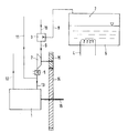
- the diesel engine 1 of the system according to FIG. 1 is equipped with a fuel tank 6 in which liquid diesel fuel is located. Fuel vapor accumulates in the free space 7 of the fuel tank 6 due to the evaporation of volatile components.
- the fuel tank 6 can be equipped with a heater 4 in order to support the fuel vapor development in the fuel tank 6.
- the heating energy can be obtained from the exhaust gases flowing out of the internal combustion engine.
- the fuel vapor is fed via a line 8 to a burner 3, in which it is burned.
- the necessary combustion air is taken from the environment via a line 10. The combustion takes place in such a way that as little nitrogen oxides and particles as possible are produced.
- the exhaust gases flowing out of your burner are fed via line 9 to a utility turbine 2, in which they are expanded.
- the power obtained from the exhaust gas energy is supplied to a shaft 16 of the drive train of the internal combustion engine 1 via a gear consisting of gear wheels 14 and 15.
- the exhaust gas energy of the gas stream flowing out of the burner can advantageously be converted into wave work.
- the exhaust gas flowing out of the utility turbine 2 is cooled in a heat exchanger 5 and reaches the combustion chambers of the internal combustion engine 1 via the line 13 together with the fresh air flowing in via the line 11.
- the CO 2 added with the exhaust gas to the combustion air reduces the nitrogen oxide formation.
- the exhaust gases flowing out of the internal combustion engine 1 via the line 12 are not used for exhaust gas recirculation.
- Diesel fuel contains about 0.05% sulfur. With those in the fuel vapor There is no sulfur in the volatile components of diesel fuel. Through the When these components are burned, a sulfur-free exhaust gas is available. This exhaust gas leaves no corrosion problems on the heat exchanger and on the Lines arise that come into contact with the exhaust gas, because it is particularly at Cooling does not lead to the condensation of sulfuric acid or sulfurous acid can. Because the fuel vapor is particle-free in a suitably set burner can burn, is not an impairment of the functionality of the Exhaust-gas-contaminated components are given by particles, which, for example, lead to the formation of deposits being able to lead. The burner is, for example, comparable to a combustion chamber in a Gas turbine constructed, with an ignition device and continuous combustion of the Air-fuel vapor mixture.
- a special evaporator for diesel fuel can also be used to generate fuel vapor be provided in connection with the burner for supplying fuel vapor stands.
Landscapes
- Engineering & Computer Science (AREA)
- Chemical & Material Sciences (AREA)
- Combustion & Propulsion (AREA)
- Mechanical Engineering (AREA)
- General Engineering & Computer Science (AREA)
- Exhaust-Gas Circulating Devices (AREA)
- Exhaust Gas After Treatment (AREA)
- Processes For Solid Components From Exhaust (AREA)
Description
Aus der DE 42 41 274 C1 geht es als bekannt hervor, eine Vorrichtung zum Einspeisen der im Freiraum eines Kraftstoffbehälters befindlichen Kraftstoffdämpfe in das Ansaugrohr einer Verbrennungskraftmaschine vorzusehen. Mit dieser Einrichtung soll verhindert werden, daß Kraftstoffdämpfe in die Umgebung gelangen.
Claims (6)
- Dieselbrennkraftmaschine mit einer Einrichtung zur Zugabe von durch die Verbrennung von Dieselkraftstoff erzeugten Abgasen zu der den Brennräumen der Dieselbrennkraftmaschine zugeführten Verbrennungsluft, dadurch gekennzeichnet, daß die der Verbrennungsluft zuzugebenden Abgase in einem Brenner (3) durch Verbrennung voll Kraftstoffdampf aus Dieselkraftstoff erzeugt werden, und daß der Brenner (3) mit einer Einrichtung zur Erzeugung und Zuführung von Kraftstoffdampf aus Dieselkraftstoff verbunden ist.
- Brennkraftmaschine nach Anspruch 1, dadurch gekennzeichnet, daß der Kraftstoffdampf für die Verbrennung im Brenner (3) aus den im Freiraum (7) eines Kraftstoffbehälters (6) befindlichen Dämpfen entnommen wird.
- Brennkraftmaschine nach Anspruch 2, dadurch gekennzeichnet, daß der Kraftstoffbehälter (6) beheizbar ist.
- Brennkraftmaschine nach einem der Ansprüche 1 bis 3, dadurch gekennzeichnet, daß der aus dem Brenner (3) abströmende Abgasstrom vor der Zugabe zur Verbrennungsluft in einem Wärmetauscher (5) gekühlt wird.
- Brennkraftmaschine nach einem der Ansprüche 1 bis 4, dadurch gekennzeichnet, daß die vom Brenner (3) abströmenden Abgase vor der Zugabe zur Verbrennungsluft einer Nutzturbine (2) zugeführt werden.
- Einrichtung nach Anspruch 4, dadurch gekennzeichnet, daß der Wärmetauscher (5) stromab von der Nutzturbine (3) angeordnet ist.
Applications Claiming Priority (2)
| Application Number | Priority Date | Filing Date | Title |
|---|---|---|---|
| DE4429674 | 1994-08-20 | ||
| DE4429674A DE4429674C2 (de) | 1994-08-20 | 1994-08-20 | Dieselbrennkraftmaschine mit einer Einrichtung zur Zugabe von Abgasen zur Verbrennungsluft |
Publications (2)
| Publication Number | Publication Date |
|---|---|
| EP0697516A1 EP0697516A1 (de) | 1996-02-21 |
| EP0697516B1 true EP0697516B1 (de) | 1998-09-23 |
Family
ID=6526236
Family Applications (1)
| Application Number | Title | Priority Date | Filing Date |
|---|---|---|---|
| EP95112733A Expired - Lifetime EP0697516B1 (de) | 1994-08-20 | 1995-08-12 | Dieselbrennkraftmaschine mit einer Einrichtung zur Zugabe von Abgasen zur Verbrennungsluft |
Country Status (3)
| Country | Link |
|---|---|
| EP (1) | EP0697516B1 (de) |
| AT (1) | ATE171513T1 (de) |
| DE (1) | DE4429674C2 (de) |
Families Citing this family (2)
| Publication number | Priority date | Publication date | Assignee | Title |
|---|---|---|---|---|
| DE19845396C2 (de) * | 1998-10-02 | 2002-07-18 | Daimler Chrysler Ag | Verfahren zur Abtrennung einer schwefelarmen Kraftstofffraktion aus einem motorischem Kraftstoff an Bord eines Kraftfahrzeugs |
| DE19901252A1 (de) * | 1999-01-15 | 2000-07-27 | Reinhard Leithner | Brennkraftmaschine |
Family Cites Families (6)
| Publication number | Priority date | Publication date | Assignee | Title |
|---|---|---|---|---|
| US4212163A (en) * | 1978-06-16 | 1980-07-15 | Mikina Stanley J | Heat engine |
| US4610141A (en) * | 1984-09-21 | 1986-09-09 | Wang Lin Shu | Compound engine with plural stage intercooled exhaust pump |
| US5207734A (en) * | 1991-07-22 | 1993-05-04 | Corning Incorporated | Engine exhaust system for reduction of hydrocarbon emissions |
| DE4235075C2 (de) * | 1992-10-17 | 1996-06-20 | Daimler Benz Ag | Ansaugleitung einer mehrzylindrigen Brennkraftmaschine |
| DE4241274C2 (de) * | 1992-12-08 | 1999-02-11 | Freudenberg Carl Fa | Vorrichtung zum Einspeisen der im Freiraum eines Kraftstoffbehälters befindlichen Dämpfe in das Ansaugrohr einer Verbrennungskraftmaschine |
| DE9421145U1 (de) * | 1994-04-28 | 1995-05-04 | Mtu Motoren- Und Turbinen-Union Friedrichshafen Gmbh, 88045 Friedrichshafen | Dieselbrennkraftmaschine mit in einer Abgasrückführleitung angeordnetem Wärmetauscher für die Abgaskühlung |
-
1994
- 1994-08-20 DE DE4429674A patent/DE4429674C2/de not_active Expired - Fee Related
-
1995
- 1995-08-12 AT AT95112733T patent/ATE171513T1/de not_active IP Right Cessation
- 1995-08-12 EP EP95112733A patent/EP0697516B1/de not_active Expired - Lifetime
Also Published As
| Publication number | Publication date |
|---|---|
| EP0697516A1 (de) | 1996-02-21 |
| DE4429674A1 (de) | 1996-02-22 |
| DE4429674C2 (de) | 1998-11-05 |
| ATE171513T1 (de) | 1998-10-15 |
Similar Documents
| Publication | Publication Date | Title |
|---|---|---|
| DE69808644T2 (de) | Reduzierung des stickoxidausstosses bei dieselmotoren | |
| WO2019020647A1 (de) | Verbrennungskraftmaschine, insbesondere für ein kraftfahrzeug, sowie verfahren zum betreiben einer solchen verbrennungskraftmaschine | |
| DE4439573A1 (de) | Verfahren zum Betrieb einer Brennkraftmaschine mit einem Abgasturbolader | |
| DE102009028925A1 (de) | Antriebsvorrichtung | |
| DE3824813C2 (de) | ||
| DE19938356A1 (de) | Befeuchtungsvorrichtung für die Einlaßluft von Brennkraftmaschinen | |
| WO2003036072A1 (de) | Vorrichtung zur erzeugung mechanischer energie | |
| DE4429674C2 (de) | Dieselbrennkraftmaschine mit einer Einrichtung zur Zugabe von Abgasen zur Verbrennungsluft | |
| DE102019005155A1 (de) | Verbrennungskraftmaschine für ein Kraftfahrzeug, insbesondere für einen Kraftwagen, sowie Verfahren zum Betreiben einer solchen Verbrennungskraftmaschine | |
| DE4310926A1 (de) | Vorrichtung und Verfahren zur Schadstoffminderung im Abgas | |
| DE102020213702A1 (de) | Brennkraftmaschine mit Heizvorrichtung im Abgasstrang | |
| DE102008008492B4 (de) | Verfahren zur Steuerung einer Kraftfahrzeug-Verbrennungsmotoranordnung | |
| DE102020004917A1 (de) | Verfahren zum Betreiben einer Verbrennungskraftmaschine eines Kraftfahrzeugs sowie Verbrennungskraftmaschine | |
| EP0904483B1 (de) | Kraftfahrzeug mit einer brennkraftmaschine mit äusserer abgasrückführung und heizvorrichtung | |
| DE102004004956A1 (de) | Vorrichtung und Verfahren zur Nachbehandlung von ölhaltigen Blow-by-Gasen einer Brennkraftmaschine | |
| DE102019006494B4 (de) | Abgasanlage für eine Verbrennungskraftmaschine eines Kraftfahrzeugs, Antriebseinrichtung für ein Kraftfahrzeug sowie Kraftfahrzeug | |
| DE102009037876B4 (de) | Brennkraftmaschine und Verfahren mit Einbringung und Zündung von Kraftstoff in mindestens einem von mehreren Abgasteilströmen und mit Abgasrückführung | |
| DE102016013704A1 (de) | Verbrennungskraftmaschine für einen Kraftwagen und Verfahren zum Betreiben einer Verbrennungskraftmaschine | |
| EP1062419B1 (de) | Vorrichtung zur rückführung von abgasen bei einem verbrennungsmotor | |
| DE2551350C2 (de) | ||
| DE102020106076A1 (de) | Brennkraftmaschine mit Ansaugluftführung und Verdichter zum Verdichten von Ansaugluft und Verfahren zu deren Betrieb | |
| DE102024115584B3 (de) | Vorrichtung zur Erzeugung eines Wassernebels für Verbrennungsmaschinen und Brennstoffheizanlagen | |
| AT503458A1 (de) | Abgasanlage einer antriebseinheit für ein kraftfahrzeug mit abgasrückführung | |
| DE102019208651A1 (de) | Antriebseinheit für ein Kraftfahrzeug mit einer Kreisprozessvorrichtung | |
| EP4083399B1 (de) | Brennkraftmaschine mit elektrischer abgasturbine und abgasnachbehandlungseinrichtung stromauf der abgasturbine |
Legal Events
| Date | Code | Title | Description |
|---|---|---|---|
| PUAI | Public reference made under article 153(3) epc to a published international application that has entered the european phase |
Free format text: ORIGINAL CODE: 0009012 |
|
| 17P | Request for examination filed |
Effective date: 19950812 |
|
| AK | Designated contracting states |
Kind code of ref document: A1 Designated state(s): AT CH FR IT LI |
|
| GRAG | Despatch of communication of intention to grant |
Free format text: ORIGINAL CODE: EPIDOS AGRA |
|
| GRAG | Despatch of communication of intention to grant |
Free format text: ORIGINAL CODE: EPIDOS AGRA |
|
| GRAH | Despatch of communication of intention to grant a patent |
Free format text: ORIGINAL CODE: EPIDOS IGRA |
|
| 17Q | First examination report despatched |
Effective date: 19980318 |
|
| GRAH | Despatch of communication of intention to grant a patent |
Free format text: ORIGINAL CODE: EPIDOS IGRA |
|
| GRAA | (expected) grant |
Free format text: ORIGINAL CODE: 0009210 |
|
| AK | Designated contracting states |
Kind code of ref document: B1 Designated state(s): AT CH FR IT LI |
|
| REF | Corresponds to: |
Ref document number: 171513 Country of ref document: AT Date of ref document: 19981015 Kind code of ref document: T |
|
| REG | Reference to a national code |
Ref country code: CH Ref legal event code: EP |
|
| REG | Reference to a national code |
Ref country code: CH Ref legal event code: NV Representative=s name: DIPL.-ING. ETH H. R. WERFFELI PATENTANWALT |
|
| ET | Fr: translation filed | ||
| PLBE | No opposition filed within time limit |
Free format text: ORIGINAL CODE: 0009261 |
|
| STAA | Information on the status of an ep patent application or granted ep patent |
Free format text: STATUS: NO OPPOSITION FILED WITHIN TIME LIMIT |
|
| 26N | No opposition filed | ||
| PGFP | Annual fee paid to national office [announced via postgrant information from national office to epo] |
Ref country code: CH Payment date: 20010716 Year of fee payment: 7 |
|
| PGFP | Annual fee paid to national office [announced via postgrant information from national office to epo] |
Ref country code: AT Payment date: 20010725 Year of fee payment: 7 |
|
| PGFP | Annual fee paid to national office [announced via postgrant information from national office to epo] |
Ref country code: FR Payment date: 20010801 Year of fee payment: 7 |
|
| PG25 | Lapsed in a contracting state [announced via postgrant information from national office to epo] |
Ref country code: AT Free format text: LAPSE BECAUSE OF NON-PAYMENT OF DUE FEES Effective date: 20020812 |
|
| PG25 | Lapsed in a contracting state [announced via postgrant information from national office to epo] |
Ref country code: LI Free format text: LAPSE BECAUSE OF NON-PAYMENT OF DUE FEES Effective date: 20020831 Ref country code: CH Free format text: LAPSE BECAUSE OF NON-PAYMENT OF DUE FEES Effective date: 20020831 |
|
| REG | Reference to a national code |
Ref country code: CH Ref legal event code: PL |
|
| PG25 | Lapsed in a contracting state [announced via postgrant information from national office to epo] |
Ref country code: FR Free format text: LAPSE BECAUSE OF NON-PAYMENT OF DUE FEES Effective date: 20030430 |
|
| REG | Reference to a national code |
Ref country code: FR Ref legal event code: ST |
|
| PG25 | Lapsed in a contracting state [announced via postgrant information from national office to epo] |
Ref country code: IT Free format text: LAPSE BECAUSE OF NON-PAYMENT OF DUE FEES;WARNING: LAPSES OF ITALIAN PATENTS WITH EFFECTIVE DATE BEFORE 2007 MAY HAVE OCCURRED AT ANY TIME BEFORE 2007. THE CORRECT EFFECTIVE DATE MAY BE DIFFERENT FROM THE ONE RECORDED. Effective date: 20050812 |