EP0695586A2 - Device for supplying the containers of a distribution conveyor - Google Patents
Device for supplying the containers of a distribution conveyor Download PDFInfo
- Publication number
- EP0695586A2 EP0695586A2 EP95810480A EP95810480A EP0695586A2 EP 0695586 A2 EP0695586 A2 EP 0695586A2 EP 95810480 A EP95810480 A EP 95810480A EP 95810480 A EP95810480 A EP 95810480A EP 0695586 A2 EP0695586 A2 EP 0695586A2
- Authority
- EP
- European Patent Office
- Prior art keywords
- product
- window
- belt
- ribbed belt
- distribution conveyor
- Prior art date
- Legal status (The legal status is an assumption and is not a legal conclusion. Google has not performed a legal analysis and makes no representation as to the accuracy of the status listed.)
- Withdrawn
Links
Images


Classifications
-
- B—PERFORMING OPERATIONS; TRANSPORTING
- B07—SEPARATING SOLIDS FROM SOLIDS; SORTING
- B07C—POSTAL SORTING; SORTING INDIVIDUAL ARTICLES, OR BULK MATERIAL FIT TO BE SORTED PIECE-MEAL, e.g. BY PICKING
- B07C1/00—Measures preceding sorting according to destination
- B07C1/02—Forming articles into a stream; Arranging articles in a stream, e.g. spacing, orientating
- B07C1/025—Devices for the temporary stacking of objects provided with a stacking and destacking device (interstack device)
-
- B—PERFORMING OPERATIONS; TRANSPORTING
- B07—SEPARATING SOLIDS FROM SOLIDS; SORTING
- B07C—POSTAL SORTING; SORTING INDIVIDUAL ARTICLES, OR BULK MATERIAL FIT TO BE SORTED PIECE-MEAL, e.g. BY PICKING
- B07C1/00—Measures preceding sorting according to destination
- B07C1/02—Forming articles into a stream; Arranging articles in a stream, e.g. spacing, orientating
- B07C1/04—Forming a stream from a bulk; Controlling the stream, e.g. spacing the articles
-
- B—PERFORMING OPERATIONS; TRANSPORTING
- B65—CONVEYING; PACKING; STORING; HANDLING THIN OR FILAMENTARY MATERIAL
- B65G—TRANSPORT OR STORAGE DEVICES, e.g. CONVEYORS FOR LOADING OR TIPPING, SHOP CONVEYOR SYSTEMS OR PNEUMATIC TUBE CONVEYORS
- B65G2207/00—Indexing codes relating to constructional details, configuration and additional features of a handling device, e.g. Conveyors
- B65G2207/18—Crossing conveyors
Definitions
- the invention relates to a device for loading the containers of a distribution conveyor with flat products, in particular mail items, with a preferably inclined storage surface and means for conveying a product placed thereon in a clocked manner into a container.
- a device of this type is known in the prior art from EP-A-0 519 375. This document shows in FIG. 10 such a device which has a flap which can be pivoted away at the lower end of the inclined storage surface.
- a rotatable roller is mounted above the flap, which engages in an opening of the storage surface and cooperates with a clamping roller for gripping a mail item, which can be pivoted against the driven roller under spring pressure.
- the invention has for its object to provide a device of the type mentioned, which ensures a gentler treatment of the flat products to be conveyed and which is particularly suitable for conveying mail items.
- the device is intended, in particular, to deliver mail pieces of different thickness, surface area and mass equally precisely into a predetermined container of a distribution conveyor.
- the object is achieved in a generic device in that the storage area is formed by a window of an endless ribbed belt that can be moved between rest positions.
- the flat products can be placed in a window of the ribbed belt and, in this, preferably thrown off obliquely downwards into a predetermined container of the distribution conveyor.
- the product only lies against the rib of the belt at the front or back and is not clamped in any way.
- the conveyance of the belt is essentially independent of the thickness of the product, its surface and its weight.
- the device according to the invention enables the ribs to be positioned precisely, so that they can be dispensed very precisely, and thus high performance. Since very different mail pieces can be handled, they have to be sorted less precisely than before. Tests have shown that at least three mail items per second can be conveyed with the device according to the invention.
- the device according to the invention is characterized by a very simple construction and few individual parts.
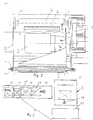
- the device 1 has a frame 12 on which a belt drive roller 4 and a deflection roller 5 are rotatably mounted.
- the drive roller 4 is connected via a drive member 3 to a controllable motor 2 fastened to the frame 12.
- An endless rib belt 6 with four vertically projecting ribs 7 and correspondingly four windows 8 is placed over the two rollers 4 and 5.
- the band 6 has at least one opening 28, to which a light barrier 25 responds, which is attached to a holder 29 fixed to the frame.
- the light barrier 25 has in the usual way a light source 26 and a reflector which emit a pulse when an opening 28 passes through the light barrier.
- the light barrier 25 can by another similarly acting means, be replaced, for example, by magnetic means.
- the ribs 7 extend essentially over the entire width of the band 6.
- a sheet 9 is attached to the frame next to the band 6 and has a side wall 9b as a side stop and a guide wall covering the upper run 6a of the band 6 at a distance 9a.
- a window 8 located under the sheet 9 thus forms a laterally open shaft 40 with the sheet 9 (FIG. 1).
- the opening of the shaft 40 is on the left, from where, according to FIG. 3, the products 21 are each placed in a shaft 40.
- the device 1 in a mail sorting system, seen in the conveying direction, there is, for example, a feeder 13, a reader 14 and a feed belt 15 in front of the device 1 according to FIG. 3 Window 8 and thus be placed between two adjacent ribs 7 of the band 6.
- the arrow 17 indicates the direction in which the products 21 are thrown onto the belt 6.
- the sheet 9 forms a guide with an upper wall 9a and with the side wall 9b a stop for a product 21 to be inserted.
- a distribution conveyor 30 Seen in the conveying direction according to the device 1, a distribution conveyor 30 is arranged, which on a rotating drive element 31 has a plurality of containers arranged one behind the other 32, which can be opened for receiving a product 21 below the device.
- Such a distribution conveyor is the subject of Swiss patent application No. 01 962/94.
- the distribution conveyor 30 can also be another known distribution conveyor.
- the containers 32 shown in FIG. 1 each have a locking axis about a pivot axis 33 and control element 35 pivotable side wall 34.
- the side wall 34 is given away in the direction of travel immediately in front of the device 1 in such a way that a product 21 dropped by the device 1 obliquely downwards can be placed in the container 32 in the direction of the arrow 36.
- it is essential that the products 21 are thrown off the device 1 at exactly the right time and in a clocked manner to the distribution conveyor 30.
- a plurality of devices 1 are assigned to one distribution conveyor 30.
- the devices 1 are then preferably loaded alternately from the left or from the right.
- the feed belt 15 is then in the view according to FIG. 3 in the one case on the right of the device 1 and the side wall 9b is accordingly on the left. In the device 1 according to the invention, loading from the left or right is thus readily possible.
- the control of the belt 6 is explained in more detail below with reference to FIGS. 4 to 7.
- the belt 6 is in the position shown in FIG. 4 for loading the device 1 with a product 21.
- a window 8 of the run 6a approximately in the middle between the rollers 4 and 5.
- the belt 6 is briefly stopped in the position shown in FIG. This corresponds to one of the positions A in the illustration according to FIG. 7.
- the belt 6 is accelerated so that the product 21 is moved downwards in the direction of the arrow 23 according to FIG.
- a product 21 is pushed downwards by a rib 7b. If the rib 7b is approximately in the position shown in FIG.
- FIG. 7 shows schematically how the dropped product 21 leaves the device 1 downwards and is thrown into the container 32 moving to the right in FIG.
Abstract
Description
Die Erfindung betrifft eine Vorrichtung zum Beschicken der Behälter eines Verteilförderers mit flachen Produkten, insbesondere Poststücken, mit einer vorzugsweise geneigten Ablagefläche und Mitteln, um ein auf diese gelegtes Produkt getaktet in einen Behälter zu fördern.
Eine Vorrichtung dieser Art ist im Stand der Technik durch die EP - A - 0 519 375 bekannt geworden. Diese Druckschrift zeigt in Figur 10 eine solche Vorrichtung, die am unteren Ende der geneigt angeordneten Ablagefläche eine wegschwenkbare Klappe aufweist. Über der Klappe ist eine drehbare Rolle gelagert, die in eine Öffnung der Ablagefläche eingreift und zum Fassen eines Poststückes mit einer Klemmrolle zusammenarbeitet, die unter Federdruck schwenkbar an die angetriebene Rolle anlegbar ist. Bei zurückgeschwenkter Klappe kann ein zwischen den Rollen festgehaltenes Poststück durch Drehen der angetriebenen Rolle nach unten in einen Behälter eines Verteilförderers abgegeben werden. Bei dieser Vorrichtung wird als nachteilig angesehen, dass empfindliche Güter, wie beispielsweise Brillengläser oder Compact-Discs durch den Druck der beiden Rollen beschädigt werden können.The invention relates to a device for loading the containers of a distribution conveyor with flat products, in particular mail items, with a preferably inclined storage surface and means for conveying a product placed thereon in a clocked manner into a container.
A device of this type is known in the prior art from EP-A-0 519 375. This document shows in FIG. 10 such a device which has a flap which can be pivoted away at the lower end of the inclined storage surface. A rotatable roller is mounted above the flap, which engages in an opening of the storage surface and cooperates with a clamping roller for gripping a mail item, which can be pivoted against the driven roller under spring pressure. When the flap is pivoted back, a piece of mail held between the rollers can be discharged into a container of a distribution conveyor by rotating the driven roller downward. This device is considered to be disadvantageous in that sensitive goods, such as spectacle lenses or compact discs, can be damaged by the pressure of the two rollers.
Der Erfindung liegt die Aufgabe zugrunde, eine Vorrichtung der genannten Art zu schaffen, die eine schonendere Behandlung der zu fördernden flachen Produkten gewährleistet und die sich insbesondere zum Fördern von Poststücken eignet. Die Vorrichtung soll insbesondere Poststücke unterschiedlicher Dicke, Oberfläche und Masse gleichermassen präzis in einen vorbestimmten Behälter eines Verteilförderers abgeben.The invention has for its object to provide a device of the type mentioned, which ensures a gentler treatment of the flat products to be conveyed and which is particularly suitable for conveying mail items. The device is intended, in particular, to deliver mail pieces of different thickness, surface area and mass equally precisely into a predetermined container of a distribution conveyor.
Die Aufgabe ist bei einer gattungsgemässen Vorrichtung dadurch gelöst, dass die Ablagefläche durch ein Fenster eines endlosen, zwischen Ruhepositionen bewegbaren Rippenbandes gebildet ist. Mit der erfindungsgemässen Vorrichtung können die flachen Produkte in ein Fenster des Rippenbandes eingelegt und in diesem vorzugsweise schräg nach unten in einen vorbestimmten Behälter des Verteilförderers abgeworfen werden. Das Produkt liegt lediglich vorne oder hinten an einer Rippe des Bandes an und wird in keiner Weise geklemmt. Die Förderung des Bandes ist im wesentlichen unanbhängig von der Dicke des Produktes, seiner Oberfläche und seinem Gewicht. Die erfindungsgemässe Vorrichtung ermöglicht durch eine genaue Positionierbarkeit der Rippen eine sehr präzise Abgabe und dadurch eine hohe Leistung. Da sehr unterschiedliche Poststücke behandelt werden können, müssen diese weniger genau als bisher vorsortiert werden. Versuche haben gezeigt, dass mit der erfindungsgemässen Vorrichtung mindestens drei Poststücke pro Sekunde gefördert werden können. Schliesslich zeichnet sich die erfindungsgemäßse Vorrichtung durch einen sehr einfachen Aufbau und wenige Einzelteile aus.The object is achieved in a generic device in that the storage area is formed by a window of an endless ribbed belt that can be moved between rest positions. With the device according to the invention, the flat products can be placed in a window of the ribbed belt and, in this, preferably thrown off obliquely downwards into a predetermined container of the distribution conveyor. The product only lies against the rib of the belt at the front or back and is not clamped in any way. The conveyance of the belt is essentially independent of the thickness of the product, its surface and its weight. The device according to the invention enables the ribs to be positioned precisely, so that they can be dispensed very precisely, and thus high performance. Since very different mail pieces can be handled, they have to be sorted less precisely than before. Tests have shown that at least three mail items per second can be conveyed with the device according to the invention. Finally, the device according to the invention is characterized by a very simple construction and few individual parts.
Weitere vorteilhafte Merkmale ergeben sich aus den abhängigen Patentansprüchen, der nachfolgenden Beschreibung sowie der Zeichnung.Further advantageous features result from the dependent claims, the following description and the drawing.
Ein Ausführungsbeispiel der Erfindung wird nachfolgend anhand der Zeichnung erläutert. Es zeigen:
- Fig. 1
- Eine Seitenansicht einer erfindungsgemässen Vorrichtung sowie eine Teilansicht eines Verteilförderers,
- Fig. 2
- eine teilweise geschnittene Draufsicht auf die Vorrichtung gemäss
Figur 1, - Fig. 3
- schematisch den Bewegungsablauf eines Poststückes im Bereich der erfindungsgemässen Vorrichtung,
- Fig. 4 bis 6
- schematisch die Abgabe eines Produktes an den Verteilförderer, und
- Fig. 7
- die Laufgeschwindigkeit des Rippenbandes in Abhängigkeit von der Zeit.
- Fig. 1
- A side view of a device according to the invention and a partial view of a distribution conveyor,
- Fig. 2
- 2 shows a partially sectioned top view of the device according to FIG. 1,
- Fig. 3
- schematically the sequence of movements of a mail item in the area of the device according to the invention,
- 4 to 6
- schematically the delivery of a product to the distribution conveyor, and
- Fig. 7
- the running speed of the ribbed belt as a function of time.
Die Vorrichtung 1 weist gemäss den Figuren 1 und 2 ein Gestell 12 auf, an dem eine Bandantriebsrolle 4 und eine Umlenkrolle 5 drehbar gelagert sind. Die Antriebsrolle 4 ist über ein Antriebsorgan 3 mit einem auf dem Gestell 12 befestigten steuerbaren Motor 2 verbunden. Über die beiden Rollen 4 und 5 ist ein endloses Rippenband 6 mit vier vertikal abstehenden Rippen 7 und entsprechend vier Fenstern 8 gelegt.According to FIGS. 1 and 2, the
Zur Steuerung der Position der Rippen weist das Band 6 wenigstens eine Öffnung 28 auf, auf die eine Lichtschranke 25 anspricht, welche an einem gestellfesten Halter 29 angebracht ist. Die Lichtschranke 25 weist in üblicher Weise eine Lichtquelle 26 und einen Reflektor auf, die beim Durchgang einer Öffnung 28 durch die Lichtschranke einen Impuls abgeben. Die Lichtschranke 25 kann durch ein anderes ähnlich wirkendes Mittel, beispielsweise durch magnetisch arbeitende Mittel ersetzt sein.To control the position of the ribs, the
Die Rippen 7 erstrecken sich gemäss Figur 2 im wesentlichen über die gesamte Breite des Bandes 6. Seitlich neben dem Band 6 ist ein Blech 9 gestellfest angebracht, das eine seitliche Wandung 9b als Seitenanschlag sowie eine den oberen Trum 6a des Bandes 6 im Abstand überdeckende Führungswand 9a aufweist. Ein sich unter dem Blech 9 befindliches Fenster 8 bildet somit mit dem Blech 9 einen seitlich offenen Schacht 40 (Fig. 1). In der Ansicht gemäss Figur 2 befindet sich die Öffnung des Schachtes 40 links, von wo gemäss Fig. 3 die Produkte 21 jeweils in einen Schacht 40 eingelegt werden.According to FIG. 2, the
Bei der bevorzugten Verwendung der Vorrichtung 1 in einer Postsortieranlage befindet sich in Förderrichtung gesehen vor der Vorrichtung 1 gemäss Figur 3 beispielsweise ein Anleger 13, ein Leser 14 und ein Zuführband 15. Auf dem Zuführband 15 sind die flachen Produkte 21 vereinzelt und können seitlich in ein Fenster 8 und somit zwischen zwei benachbarte Rippen 7 des Bandes 6 gelegt werden. In Figur 3 zeigt der Pfeil 17 die Richtung an, in welcher die Produkte 21 auf das Band 6 geworfen werden. Das Blech 9 bildet mit einer oberen Wandung 9a eine Führung und mit der Seitenwand 9b einen Anschlag für ein einzulegendes Produkt 21. In Förderrichtung gesehen nach der Vorrichtung 1 ist ein Verteilförderer 30 angeordnet, der an einem umlaufend angetriebenen Zugorgan 31 eine Mehrzahl von hintereinander angeordneten Behältern 32 aufweist, die zur Aufnahme jeweils eines Produktes 21 unterhalb der Vorrichtung aufklappbar sind. Ein solcher Verteilförderer ist Gegenstand der schweizerischen Patentanmeldung Nr. 01 962/94. Der Verteilförderer 30 kann jeoch auch ein anderer bekannter Verteilförderer sein. Die in Figur 1 gezeigten Behälter 32 weisen jeweils eine um eine Schwenkachse 33 mittels eines Verriegelungs- und Steuerelementes 35 verschwenkbare Seitenwand 34 auf. Die Seitenwand 34 wird in Laufrichtung gesehen unmittelbar vor der Vorrichtung 1 so verschenkt, dass ein von der Vorrichtung 1 schräg nach unten abgeworfenes Produkt 21 in Richtung des Pfeiles 36 in den Behhälter 32 abgelegt werden kann. Für einen störungsfreien Transport ist es wesentlich, dass die Produkte 21 genau rechtzeitig und getaktet zum Verteilförderer 30 von der Vorrichtung 1 abgworfen werden. In der Regel sind einem Verteilförderer 30 mehrere Vorrichtung 1 zugeordnet. Vorzugsweise werden dann die Vorrichtungen 1 abwechslungsweise von links oder von rechts beschickt. Das Zuführband 15 befindet sich dann in der Ansicht gemäss Figur 3 in den einen Fällen rechts der Vorrichtung 1 und die Seitenwand 9b dann entsprechend links. Bei der erfindungemässen Vorrichtung 1 ist somit ohne weiteres eine Beschickung von links oder rechts möglich.In the preferred use of the
Anhand der Figuren 4 bis 7 wird nachfolgend die Steuerung des Bandes 6 näher erläutert. Zum Beschicken der Vorrichtung 1 mit einem Produkt 21 ist das Band 6 in der in der Figur 4 gezeigten Position. In dieser befindet sich ein Fenster 8 des Trums 6a etwa mittig zwischen den Rollen 4 und 5. Zum Einlegen eines Produktes 21 in das Fenster 8 wird das Band 6 in der in Figur 4 gezeigten Position kurz angehalten. Dies entspricht in der Darstellung gemäss Figur 7 einer der Positionen A. Ist das Produkt 21 in das Fenster 8 eingelegt, so wird das Band 6 Beschleunigt, so dass das Produkt 21 gemäss Figur 5 in Richtung des Pfeiles 23 nach unten bewegt wird. In der Regel wird ein Produkt 21 hierbei durch eine Rippe 7b nach unten gestossen. Befindet sich die Rippe 7b etwa in der in Figur 6 gzeigten Position, so wird die Bewegung des Bandes 6 verlangsamt und die in Figur 4 gezeigte Ruhestellung angesteuert, so dass in das nachfolgende nunmehr positionierte Fenster 8a ein nächstes Produkt 21 eingelgt werden kann. Die Figur 7 zeigt schematisch, wie das abgeworfene Produkt 21 die Vorrichtung 1 nach unten verlässt und in den in Figur 6 nach rechts bewegenden Behälter 32 geworfen wird.The control of the
Trotz der erheblichen Vorteile der erfindungsgemässen Vorrichtung ist diese ersichtlich mit verhältnismässig wenigen, einfachen und robusten Bauteilen realisierbar. Erfindungsgemäss wurde somit eine Vorrichtung geschaffen, welche nicht nur den fördertechnischen Anforderungen in hervorragender Weise Rechnung trägt, sondern aufgrund ihrer einfachen und robusten Ausführbarkeit kostenmässig günstig und betrieblich äusserst zuverlässig ist.Despite the considerable advantages of the device according to the invention, it can obviously be implemented with relatively few, simple and robust components. According to the invention, a device was thus created which not only takes excellent account of the conveyor requirements, but is also inexpensive and extremely reliable in operation due to its simple and robust design.
Claims (8)
Applications Claiming Priority (2)
| Application Number | Priority Date | Filing Date | Title |
|---|---|---|---|
| CH2413/94 | 1994-08-02 | ||
| CH02413/94A CH688711A5 (en) | 1994-08-02 | 1994-08-02 | Apparatus for feeding the container of a distributing conveyor. |
Publications (2)
| Publication Number | Publication Date |
|---|---|
| EP0695586A2 true EP0695586A2 (en) | 1996-02-07 |
| EP0695586A3 EP0695586A3 (en) | 1998-01-14 |
Family
ID=4233222
Family Applications (1)
| Application Number | Title | Priority Date | Filing Date |
|---|---|---|---|
| EP95810480A Withdrawn EP0695586A3 (en) | 1994-08-02 | 1995-07-24 | Device for supplying the containers of a distribution conveyor |
Country Status (3)
| Country | Link |
|---|---|
| US (1) | US5638941A (en) |
| EP (1) | EP0695586A3 (en) |
| CH (1) | CH688711A5 (en) |
Cited By (2)
| Publication number | Priority date | Publication date | Assignee | Title |
|---|---|---|---|---|
| EP1393822A1 (en) * | 2002-08-30 | 2004-03-03 | Siemens Schweiz AG | Apparatus for feeding flat items to be sorted to a precise position of an input device of a sorting feeder |
| WO2004037449A1 (en) * | 2002-10-23 | 2004-05-06 | Siemens Schweiz Ag | Device for effecting the positionally accurate conveyance of flat articles to be sorted to an input device for a sorting conveyor |
Families Citing this family (1)
| Publication number | Priority date | Publication date | Assignee | Title |
|---|---|---|---|---|
| US7464822B2 (en) * | 2005-01-05 | 2008-12-16 | Lockheed Martin Corporation | Transporting and packaging device and method of use |
Citations (2)
| Publication number | Priority date | Publication date | Assignee | Title |
|---|---|---|---|---|
| CH196294A (en) | 1936-07-09 | 1938-02-28 | Ringhoffer Tatra Werke Ag | Motor chassis for off-road vehicles. |
| EP0519375A1 (en) | 1991-06-21 | 1992-12-23 | Compagnie Generale D'automatisme Cga-Hbs | Loading apparatus for sorting machine for flat objects such as letters |
Family Cites Families (10)
| Publication number | Priority date | Publication date | Assignee | Title |
|---|---|---|---|---|
| FR1210748A (en) * | 1958-06-13 | 1960-03-10 | Hotchkiss Brandt | Device for loading a letter or other document into a bucket or other movable box |
| US3339699A (en) * | 1965-04-19 | 1967-09-05 | Spra Con Co | Article feeding means for conveyors |
| US4267917A (en) * | 1977-09-15 | 1981-05-19 | Redington Inc. | Article transfer mechanism |
| FR2499033A1 (en) * | 1981-02-03 | 1982-08-06 | Nantaise Biscuiterie | METHOD AND DEVICE FOR REGULARIZING THE TRANSFER OF IDENTICAL SOLID PRODUCTS |
| JPS61248813A (en) * | 1985-04-24 | 1986-11-06 | Mitsubishi Electric Corp | Material transfer control device for saddle chain conveyor |
| IT1217694B (en) * | 1988-05-23 | 1990-03-30 | Francesco Canziani | METHOD FOR THE CONTROL OF THE EXACT POSITIONING OF THE OBJECTS TO BE SORTED IN AN AUTOMATIC SORTING SYSTEM |
| FR2667806B1 (en) * | 1990-10-10 | 1994-10-07 | Didier Thieriot | DEVICE FOR THE QUICK DISTRIBUTION OF FLAT OBJECTS IN A BUCKET CONVEYOR. |
| FR2677626B1 (en) * | 1991-06-14 | 1995-08-25 | Bertin & Cie | DEVICE FOR TRANSFERRING FLAT OBJECTS, IN PARTICULAR FOR A POSTAL SORTING MACHINE. |
| FR2700527B1 (en) * | 1993-01-18 | 1995-04-07 | Bertin & Cie | Device for temporary storage of flat objects. |
| US5495932A (en) * | 1994-03-09 | 1996-03-05 | A. C. Horn & Co. | Conveyor apparatus for collating bagged food products |
-
1994
- 1994-08-02 CH CH02413/94A patent/CH688711A5/en not_active IP Right Cessation
-
1995
- 1995-07-24 EP EP95810480A patent/EP0695586A3/en not_active Withdrawn
- 1995-07-25 US US08/507,026 patent/US5638941A/en not_active Expired - Fee Related
Patent Citations (2)
| Publication number | Priority date | Publication date | Assignee | Title |
|---|---|---|---|---|
| CH196294A (en) | 1936-07-09 | 1938-02-28 | Ringhoffer Tatra Werke Ag | Motor chassis for off-road vehicles. |
| EP0519375A1 (en) | 1991-06-21 | 1992-12-23 | Compagnie Generale D'automatisme Cga-Hbs | Loading apparatus for sorting machine for flat objects such as letters |
Cited By (3)
| Publication number | Priority date | Publication date | Assignee | Title |
|---|---|---|---|---|
| EP1393822A1 (en) * | 2002-08-30 | 2004-03-03 | Siemens Schweiz AG | Apparatus for feeding flat items to be sorted to a precise position of an input device of a sorting feeder |
| WO2004020114A1 (en) * | 2002-08-30 | 2004-03-11 | Siemens Schweiz Ag | Device for transferring in a precise position flat objects to be sorted towards the input device of a sorting conveyor |
| WO2004037449A1 (en) * | 2002-10-23 | 2004-05-06 | Siemens Schweiz Ag | Device for effecting the positionally accurate conveyance of flat articles to be sorted to an input device for a sorting conveyor |
Also Published As
| Publication number | Publication date |
|---|---|
| EP0695586A3 (en) | 1998-01-14 |
| CH688711A5 (en) | 1998-01-30 |
| US5638941A (en) | 1997-06-17 |
Similar Documents
| Publication | Publication Date | Title |
|---|---|---|
| DE3303184C2 (en) | ||
| EP0708691B1 (en) | Sorting installation, in particular for mail | |
| DE102009017211B3 (en) | Device for taking back empties, in particular plastic bottles and metal cans | |
| DE102016109313A1 (en) | Slip for general cargo and method of using such a chute | |
| DE3144449A1 (en) | DEVICE FOR GROUPING OBJECTS, IN PARTICULAR UPRIGHT BOTTLES | |
| EP0708693B1 (en) | Sorting installation, in particular for mail | |
| DE10141375C1 (en) | Device for separating mail items in thickness classes | |
| DE19535330B4 (en) | sorter | |
| EP2303742B1 (en) | Transfer device for mail | |
| EP0616303A1 (en) | Device for the vertical transport of coins | |
| DE3312225A1 (en) | DEVICE FOR WITHDRAWING PAPER BANKNOTES PRESENT AT THE OUTPUT STATION OF AN AUTOMATIC BANK SWITCH | |
| DE2614711C2 (en) | Device for transporting containers to treatment or packaging machines, in particular bottle washing machines | |
| DE3346129C2 (en) | Device for sorting waste containing used glass | |
| EP0695586A2 (en) | Device for supplying the containers of a distribution conveyor | |
| DE3839304A1 (en) | DEVICE FOR DEPOSITING COPY SHEETS | |
| DE1499537C3 (en) | Device for conveying letters to a viewing station | |
| DE102012103783A1 (en) | Linear conveyor and feeding method for fasteners | |
| EP2174897B1 (en) | Device for guiding returnable containers | |
| EP0859670B1 (en) | Sorting arrangement, in particular for items of post | |
| EP2045024B1 (en) | Sorting device for plants | |
| DE4126554A1 (en) | Automatic programmable supply system for goods - uses vacuum entrainment mechanism and conveyor for gentle handling | |
| EP0224105A1 (en) | Apparatus for sorting objects having a disc shape in dependence upon their diameter, particularly coins | |
| DE4323565A1 (en) | Sorting device, in particular for mail | |
| AT403471B (en) | CHAIN BUCKET CONVEYOR | |
| DE2746635A1 (en) | Coin sorting system for various denominations - has continuous belt with contact pads to eject coins through apertures in top cover |
Legal Events
| Date | Code | Title | Description |
|---|---|---|---|
| PUAI | Public reference made under article 153(3) epc to a published international application that has entered the european phase |
Free format text: ORIGINAL CODE: 0009012 |
|
| AK | Designated contracting states |
Kind code of ref document: A2 Designated state(s): DE DK FR GB IT |
|
| PUAL | Search report despatched |
Free format text: ORIGINAL CODE: 0009013 |
|
| AK | Designated contracting states |
Kind code of ref document: A3 Designated state(s): DE DK FR GB IT |
|
| 17P | Request for examination filed |
Effective date: 19980508 |
|
| STAA | Information on the status of an ep patent application or granted ep patent |
Free format text: STATUS: THE APPLICATION IS DEEMED TO BE WITHDRAWN |
|
| 18D | Application deemed to be withdrawn |
Effective date: 20000201 |