EP0695052B1 - Procédé d'entrelacement et de désentrelacement de trames SDH et système correspondant - Google Patents
Procédé d'entrelacement et de désentrelacement de trames SDH et système correspondant Download PDFInfo
- Publication number
- EP0695052B1 EP0695052B1 EP95401761A EP95401761A EP0695052B1 EP 0695052 B1 EP0695052 B1 EP 0695052B1 EP 95401761 A EP95401761 A EP 95401761A EP 95401761 A EP95401761 A EP 95401761A EP 0695052 B1 EP0695052 B1 EP 0695052B1
- Authority
- EP
- European Patent Office
- Prior art keywords
- interleaving
- pointer
- law
- frame
- area
- Prior art date
- Legal status (The legal status is an assumption and is not a legal conclusion. Google has not performed a legal analysis and makes no representation as to the accuracy of the status listed.)
- Expired - Lifetime
Links
- 238000000034 method Methods 0.000 title claims description 22
- 230000005540 biological transmission Effects 0.000 claims description 14
- 238000005056 compaction Methods 0.000 description 18
- 238000012937 correction Methods 0.000 description 5
- 241001644893 Entandrophragma utile Species 0.000 description 4
- 238000004891 communication Methods 0.000 description 4
- 238000000605 extraction Methods 0.000 description 4
- 238000004364 calculation method Methods 0.000 description 3
- 238000010586 diagram Methods 0.000 description 3
- 230000000694 effects Effects 0.000 description 3
- 238000012545 processing Methods 0.000 description 2
- 230000001915 proofreading effect Effects 0.000 description 2
- 230000008929 regeneration Effects 0.000 description 2
- 238000011069 regeneration method Methods 0.000 description 2
- 238000004353 relayed correlation spectroscopy Methods 0.000 description 2
- 230000001360 synchronised effect Effects 0.000 description 2
- 241001080024 Telles Species 0.000 description 1
- 240000008042 Zea mays Species 0.000 description 1
- 238000012550 audit Methods 0.000 description 1
- 230000006837 decompression Effects 0.000 description 1
- 239000006185 dispersion Substances 0.000 description 1
- 239000000835 fiber Substances 0.000 description 1
- 230000006870 function Effects 0.000 description 1
- 230000004807 localization Effects 0.000 description 1
- 238000007726 management method Methods 0.000 description 1
- 238000005259 measurement Methods 0.000 description 1
- 239000003607 modifier Substances 0.000 description 1
- 238000010606 normalization Methods 0.000 description 1
- 239000013307 optical fiber Substances 0.000 description 1
- 238000012549 training Methods 0.000 description 1
Images



Classifications
-
- H—ELECTRICITY
- H03—ELECTRONIC CIRCUITRY
- H03M—CODING; DECODING; CODE CONVERSION IN GENERAL
- H03M13/00—Coding, decoding or code conversion, for error detection or error correction; Coding theory basic assumptions; Coding bounds; Error probability evaluation methods; Channel models; Simulation or testing of codes
- H03M13/27—Coding, decoding or code conversion, for error detection or error correction; Coding theory basic assumptions; Coding bounds; Error probability evaluation methods; Channel models; Simulation or testing of codes using interleaving techniques
- H03M13/2703—Coding, decoding or code conversion, for error detection or error correction; Coding theory basic assumptions; Coding bounds; Error probability evaluation methods; Channel models; Simulation or testing of codes using interleaving techniques the interleaver involving at least two directions
- H03M13/2721—Coding, decoding or code conversion, for error detection or error correction; Coding theory basic assumptions; Coding bounds; Error probability evaluation methods; Channel models; Simulation or testing of codes using interleaving techniques the interleaver involving at least two directions the interleaver involves a diagonal direction, e.g. by using an interleaving matrix with read-out in a diagonal direction
-
- H—ELECTRICITY
- H03—ELECTRONIC CIRCUITRY
- H03M—CODING; DECODING; CODE CONVERSION IN GENERAL
- H03M13/00—Coding, decoding or code conversion, for error detection or error correction; Coding theory basic assumptions; Coding bounds; Error probability evaluation methods; Channel models; Simulation or testing of codes
- H03M13/27—Coding, decoding or code conversion, for error detection or error correction; Coding theory basic assumptions; Coding bounds; Error probability evaluation methods; Channel models; Simulation or testing of codes using interleaving techniques
- H03M13/2703—Coding, decoding or code conversion, for error detection or error correction; Coding theory basic assumptions; Coding bounds; Error probability evaluation methods; Channel models; Simulation or testing of codes using interleaving techniques the interleaver involving at least two directions
- H03M13/271—Row-column interleaver with permutations, e.g. block interleaving with inter-row, inter-column, intra-row or intra-column permutations
-
- H—ELECTRICITY
- H04—ELECTRIC COMMUNICATION TECHNIQUE
- H04J—MULTIPLEX COMMUNICATION
- H04J3/00—Time-division multiplex systems
- H04J3/02—Details
- H04J3/04—Distributors combined with modulators or demodulators
- H04J3/047—Distributors with transistors or integrated circuits
-
- H—ELECTRICITY
- H04—ELECTRIC COMMUNICATION TECHNIQUE
- H04J—MULTIPLEX COMMUNICATION
- H04J3/00—Time-division multiplex systems
- H04J3/16—Time-division multiplex systems in which the time allocation to individual channels within a transmission cycle is variable, e.g. to accommodate varying complexity of signals, to vary number of channels transmitted
- H04J3/1605—Fixed allocated frame structures
- H04J3/1611—Synchronous digital hierarchy [SDH] or SONET
-
- H—ELECTRICITY
- H04—ELECTRIC COMMUNICATION TECHNIQUE
- H04J—MULTIPLEX COMMUNICATION
- H04J2203/00—Aspects of optical multiplex systems other than those covered by H04J14/05 and H04J14/07
- H04J2203/0001—Provisions for broadband connections in integrated services digital network using frames of the Optical Transport Network [OTN] or using synchronous transfer mode [STM], e.g. SONET, SDH
- H04J2203/0028—Local loop
- H04J2203/003—Medium of transmission, e.g. fibre, cable, radio
- H04J2203/0035—Radio
-
- H—ELECTRICITY
- H04—ELECTRIC COMMUNICATION TECHNIQUE
- H04J—MULTIPLEX COMMUNICATION
- H04J2203/00—Aspects of optical multiplex systems other than those covered by H04J14/05 and H04J14/07
- H04J2203/0001—Provisions for broadband connections in integrated services digital network using frames of the Optical Transport Network [OTN] or using synchronous transfer mode [STM], e.g. SONET, SDH
- H04J2203/0089—Multiplexing, e.g. coding, scrambling, SONET
Definitions
- the field of the invention is that of processes SDH frame interleaving and deinterleaving (Synchronous Digital Hierarchy - Digital Hierarchy Synchronous) and relates more precisely to such a process giving the parity check bytes of these frames transparency to the interlacing operation.
- the invention also relates to a system interleaving and deinterleaving using such a process.
- STM-1 type frames provide a throughput of 155 Mbits / s transmission.
- the SOH section overhead is included in the bytes 1 to 9 of lines 1 to 3 and 5 to 9 while the area PT of pointers occupies bytes 1 to 9 of the fourth STM-1 frame line. Payload area occupies bytes 9 to 270 of lines 1 to 9. Reading of all these bytes is done from left to right and from top to bottom.
- pointers The function of pointers is to indicate the position of the various tributary signals in the area of useful capacity and thus make it possible to resolve the frame alignment problems without using memory buffer.
- FIG. 2 shows the structure of SOH.
- SOH is composed of an overflow of regeneration section RSOH (Regenerator Section Overhead) and an overhead of Multiplexing Section MSOH Overhead).
- RSOH Regenerator Section Overhead
- MSOH Overhead Multiplexing Section
- Bytes marked with a cross are reserved for international usage and bytes B1, B2.1, B2.2 and B2.3 of a given frame i constitute bytes of parity check of frame i-1 preceding this frame i.
- a parity check byte contained in the frame i is the sum of the bytes contained in the i-1 frame, including the parity check byte correspondent included in this frame i-1.
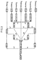
- FIG 3 shows the multiplexing structure an STM-1 frame according to CCITT recommendation G709.
- This multiplex structure has several plesiochronous tributaries of different connected flows each to a CT-i container constituting envelopes digital signals carried. These containers are connected to CTV-i virtual containers, each consisting of a container and an overflow. Virtual containers CTV-i cooperate with UAF-i tributary units composed of a lower order virtual container and its associated pointer.
- GUAF-i are groups tributary unit that represents a structure virtual frame for multiplexing UAF-i of different sizes.
- DSUs are units which are multiplexed to form an STM-1 type frame.
- An interlacing of N frames STM-1 constitutes an STM-N type frame which is transmitted to a receiver, over the air or by wired connection (cable, optical fiber, ).
- pointers In addition, in the case of multi-frame transport, pointers occupy only one byte per frame.
- the present invention aims in particular to provide an interleaving method and system (at level of a transmitter) and deinterlacing (at the level of a receiver) of SDH frames not suffering from aforementioned drawbacks.
- Another object of the invention is to provide a such interlacing that does not corrupt the value of the parity check byte B1 nor that of the 24-tuple B2.1, B2.2, B2.3.
- the method of the invention advantageously comprises 24-tuple B2 correction step after compaction and interlacing, as well as after unzipping and deinterlacing, to remedy the corruption of this byte due to compaction.
- the invention also relates to a system pointer interlacing and deinterlacing SDH frames implementing this method, as well as a corresponding transmitter and receiver.
- interlacing The problem with interlacing is that it does not it should not corrupt the parity check bytes B1 and B2.1, B2.2 and B2.3. So the interlacing should respect the position of the modulo 24 bits in the frame interlaced so that the 24-tuples B2.1, B2.2 and B2.3 do not not be corrupt. Respecting the position of the bits modulo 24, we necessarily respect the position of modulo 8 bits and an interlacing that doesn't corrupts what 24-tuplet therefore does not corrode byte B1 either.
- the interleaving is done line by line.
- the tables in Figures 5 and 6 represent the natural order of the bits to be interleaved when they are arranged in tables of 24 columns and 87 and 90 lines respectively.
- the table in the figure 5 contains 2088 bits and that of FIG. 6 contains 2160.
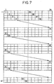
- the interlacing of the invention may simply consist in re-reading these tables as shown in Figure 7.
- Figure 7 shows the replay order of a table corresponding to that of figure 5.
- This proofreading is done here diagonally, i.e. the first bit read is that of the 1st line, 1st column, the second bit read is that of the 2nd line, 2nd column, and so on until reaching the 24th row, 24th column.
- the proofreading process then resumes on the 26th row, 1st column, and not not on the 25th line, so as to respect a 24-bit interval between bits of rank 576 (24x24) and 577.
- the 87th line is reached (for the read the 84th bit)
- the replay process resumes in the first row of the 13th column.
- This table is then read line by line to place the corresponding bits in a frame, constituting the interlaced frame.
- Bit interleaving is done by retaining their modulo 24 rank in the frame, the bytes parity checks are not corrupt.
- the embodiment of the invention given above ensures that 83 bits (86 in the case of fourth line) in the interlaced block are found at least 25 bits apart from each other in the deinterlaced block.
- 83 bits (86 in the case of fourth line) in the interlaced block are found at least 25 bits apart from each other in the deinterlaced block.
- a notebook of charges imposing that a bundle of length errors equal to 80 bits (Lmax) does not prevent recognition a pointer.
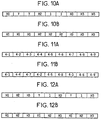
- a specific treatment can be implemented to also ensure a dispersion of the bits of ADU-4 administrative unit and unit pointers ADU-32 administrative documents: these appear in the fourth line of the STM-1 frame as shown in Figures 10A and 10B.
- Figure 10A shows the structure of the pointer PT of administrative unit UAD-4. It has 9 bytes of which only the bytes H1, H2 and H3 form the pointer. Referring to Figure 9, we see that if we use the interlacing presented above, bits of H1, H2 and H3 will be assembled in groups of 3 by the interlacing operation. The invention having to disperse these bits, it is necessary to perform before (or after) interleaving an operation on these bytes so that this grouping of bits does not not happen. The same problem arises for the pointer PT of administrative unit UAD-32 represented at Figure 10B.
- the present invention therefore provides compact the area of pointers, this compacting consisting to modify the position of at least two bytes of the zone pointers so that after interlacing and compacting each pair of pointer bits is separated at least Lmax, Lmax being the length of a bundle errors that may affect transmission without cause pointer error.
- This compacting is given with reference to FIGS. 11A and 11B.
- FIG. 11A generally represents the PT area of an STM-1 frame, the 9 bytes of this part of the fourth line being referenced 4.1 to 4.9.
- the invention proposes to carry out a compaction of these bytes so that the interleaving operation disperses their bits in the interlaced frame.
- this area has the structure shown in Figure 11B after the operation of compaction.
- Bytes 4.1, 4.5 and 4.9 remain at their locations, bytes 4.2 and 4.4, 4.3 and 4.7 and finally 4.6 and 4.8 being respectively swapped between them.
- byte B2-1 normally relates to bytes 4.1, 4.4 and 4.7 but after compacting these bytes are respectively 4.1, 4.2 and 4.3.
- B2.2 and B2.3 normally relate to bytes 4.2, 4.5, 4.8 and 4.3, 4.6, 4.9 respectively, while the compacting operation replaces them by 4.4, 4.5, 4.6 and 4.7, 4.8, 4.9 respectively. This is why the method of the invention proposes to effect a correction of this 24-tuplet after the compacting operation, by replacing the bytes B2.1, B2.2 and B2.3 by bytes B2.1 '.
- B2.1 ' B2.1 - 4.2 - 4.3 + 4.4 + 4.7
- B2.2 ' B2.2 - 4.4 - 4.6 + 4.2 + 4.8
- B2.3 ' B2.3 - 4.7 - 4.8 + 4.3 + 4.6
- the present invention also relates to a interlacing and deinterlacing system of STM-1 or STM-N SDH frame pointers transmitted between a transmitter and a receiver.
- Figure 13 is a block diagram of part of a transmitter implementing the method of the invention.
- the processing means shown in the figure 13 include an entry E of a frame to be interleaved and a device 135 for extracting the locking word from frame and synchronization.
- a device 135 for extracting the locking word from frame and synchronization.
- At the entrance E can by example be applied a 155/4 demultiplexed train STM-1 or STM-4 frame bits.
- a compaction module 130 receives this signal E and compresses the bytes from the PT area.
- compaction is produced according to a compaction law which consists of change the position of at least two bytes in the zone pointers so that after interlacing and compacting each pair of pointer bits is separated at least Lmax, Lmax being the length of a bundle errors that may affect transmission without cause pointer error.
- This compaction can advantageously be produced according to FIG. 11B.
- An interleaver module 131 receives the signal output of the compacting module 130 and provides interleaving of the bits of the area of pointers and of those of the useful capacity zone according to a law of interleaving retaining the rank of the interleaved bits modulo 24, in accordance with the invention. Because of compaction and so as not to have to modify the rule of calculation of the parity check bytes, provision is made for means 132, 133, 134 for correcting the 24-tuplet B2 of the interlaced frame, provided by module 131.
- modules 132 have a pointer extraction module 133 present in the PT area, a module 134 for calculating the 24-tuplet B2 corrected and a module 132 where the 24-tuplet B2 present in the interlaced signal is replaced by the 24-tuplet corrected.
- the output signal S of module 132 constitutes the signal transmitted to the receiver of the figure 14.
- the transmission is for example hertzian and transits through repeaters. It can also be cable or fiber optic transmission.
- the receiver of FIG. 14 comprises means deinterlacing 140 of the received signal SR ensuring a deinterlacing of the interlaced frame received according to a reciprocal law of the interlacing law.
- deinterlacing is therefore to bring together bits that were dispersed by interleaving.
- the frame deinterleaved is applied to the decompression module 141 ensuring unpacking of the pointer area according to a reciprocal law of the compaction law.
- Module 141 can therefore be identical to module 130.
- the receiver also includes means for correction of the 24-tuplet B2 of the deinterlaced frame from module 141.
- These resources consist of a pointer extraction module 143 present in the area PT of the deinterleaved frame (constituting the signal of output S), a module 144 for calculating the 24-tuplet B2 corrected and a module 142 where the 24-tuplet B2 present in the deinterlaced signal is replaced by the 24-tuple corrected.
- the receiver also has a device 145 to extract the frame lock word and synchronization.
- interleaving operation can precede that of compaction and, like that of decompaction can precede that of deinterlacing. In practical, these operations are simultaneous.
Landscapes
- Engineering & Computer Science (AREA)
- Physics & Mathematics (AREA)
- Computer Networks & Wireless Communication (AREA)
- Signal Processing (AREA)
- Probability & Statistics with Applications (AREA)
- Theoretical Computer Science (AREA)
- Microelectronics & Electronic Packaging (AREA)
- Mathematical Physics (AREA)
- Detection And Prevention Of Errors In Transmission (AREA)
- Error Detection And Correction (AREA)
- Time-Division Multiplex Systems (AREA)
Description
- une zone de surdébit de section SOH (Section Overhead) ;
- une zone PT comportant notamment des pointeurs ;
- une zone de capacité utile comportant essentiellement les données utiles à transmettre.
- d'octets de verrouillage de trame A1 (11110110) et A2 (00101000) constituant un mot de verrouillage de trame ;
- d'un octet d'identification C1 permettant de repérer le rang d'un signal démultiplexé (extraction d'un octet sur N) dans la trame STM-N (trame haut débit de N fois 155 Mbits) ;
- d'un octet B1 de calcul de parité à entrelacement de bit d'ordre 8 utilisé pour la localisation de défaut à l'intérieur d'une section de régénération ;
- d'octets E1 et F1 réservés respectivement pour une voie de service et une voie utilisateur ;
- d'octets D1 à D3 qui forment un canal de communication de données à 192 Kbits/s.
- d'octets B2.1, B2.2, B2.3 utilisés pour la mesure de qualité de la section de multiplexage ;
- d'octets K1 et K2 utilisés pour la gestion de la protection automatique de section ;
- d'octets D4 à D12 formant un canal de communication de données à 576 Kbits/s ;
- d'octets réservés Z1 et 22 ;
- d'un octet E2 formant une voie de service à 64 Kbits/s.
- il utilise pour les extra-bits des emplacements du SOH qui ne sont pour l'instant pas normalisés mais qui pourraient l'être dans l'avenir; des normalisations futures peuvent donc rendre ce procédé inapplicable ;
- il ne tient pas compte des pointeurs pouvant se trouver dans la zone de capacité utile. De tels pointeurs sont notamment utilisés pour indiquer la position des conteneurs virtuels CTV-31 et CTV-32 contenus dans les unités administratives UAD-4 et UAD-31. Ils sont disposés en colonnes d'octets et ne présentent donc qu'un octet par ligne. Plus précisément, ces trois octets sont consécutifs et inscrits dans les colonnes 11, 12, 13 et 14 de la trame STM-1, à partir de la première ligne, pour le transport de quatre conteneurs virtuels de type CTV-31, et également consécutifs et inscrits dans les colonnes 13, 14 et 15 de la trame STM-1, à partir de la première ligne, pour le transport de trois conteneurs virtuels CTV-32.
- une zone de surdébit de section ;
- une zone de pointeurs ;
- une zone de capacité utile comportant notamment les données utiles à transmettre ;
et consistant, au niveau dudit récepteur, à désentrelacer ladite trame entrelacée selon une loi réciproque de ladite loi d'entrelacement ;
caractérisé en ce que ledit entrelacement est associé à un compactage de ladite zone de pointeurs réalisé selon une loi de compactage, ledit compactage consistant à modifier la position d'au moins deux octets de ladite zone de pointeurs de telle sorte qu'après entrelacement et compactage chaque couple de bits du pointeur soit séparé d'au moins Lmax, Lmax étant la longueur d'un paquet d'erreurs pouvant affecter la transmission sans provoquer d'erreur de pointeur, ledit désentrelacement étant associé à un décompactage selon une loi réciproque de ladite loi de compactage.
- la figure 1 représente une trame de base transmise dans un réseau SDH et transportant un conteneur virtuel de type CTV-4 ;
- la figure 2 représente la structure du SOH de la trame de base ;
- la figure 3 représente la structure de multiplexage d'une trame STM-1 selon la recommandation G709 du CCITT ;
- la figure 4 représente une trame de type STM-1 où les zones entrelacées dans le procédé de l'invention sont mises en évidence ;
- les figures 5 et 6 sont des tableaux représentant l'ordre naturel des bits à entrelacer lorsqu'ils sont rangés dans des tableaux de 24 colonnes et respectivement 87 et 90 lignes pour l'entrelacement spécifique de la 4ième ligne de la trame STM-1 ;
- la figure 7 représente l'ordre de relecture du tableau de la figure 5, selon un mode de mise en oeuvre préférentiel du procédé de l'invention ;
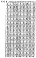
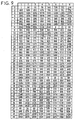
- les figures 8 et 9 représentent des parties de tableaux résultant de l'entrelacement selon l'invention ;
- les figures 10A à 12B représentent différents arrangements de la zone PT contenant des pointeurs ;
- la figure 13 est un schéma synoptique d'une partie d'un émetteur selon l'invention ;
- la figure 14 est un schéma synoptique d'une partie d'un récepteur selon l'invention.
Claims (8)
- Procédé d'entrelacement et de désentrelacement de pointeurs de trames SDH de type STM-1 ou STM-N transmises entre un émetteur et un récepteur, chaque trame comportant trois zones :ledit entrelacement consistant, au niveau dudit émetteur, à entrelacer les bits de ladite zone de pointeurs (PT) et ceux de ladite zone de capacité utile selon une loi d'entrelacement conservant aux bits entrelacés leur rang modulo 24, ledit entrelacement fournissant une trame entrelacée transmise audit récepteur,une zone de surdébit de section (SOH) ;une zone de pointeurs (PT) ;une zone de capacité utile comportant notamment les données utiles à transmettre ;
et consistant, au niveau dudit récepteur, à désentrelacer ladite trame entrelacée selon une loi réciproque de ladite loi d'entrelacement ;
caractérisé en ce que ledit entrelacement est associé à un compactage de ladite zone de pointeurs (PT) réalisé selon une loi de compactage, ledit compactage consistant à modifier la position d'au moins deux octets de ladite zone de pointeurs (PT) de telle sorte qu'après entrelacement et compactage chaque couple de bits du pointeur soit séparé d'au moins Lmax, Lmax étant la longueur d'un paquet d'erreurs pouvant affecter la transmission sans provoquer d'erreur de pointeur, ledit désentrelacement étant associé à un décompactage selon une loi réciproque de ladite loi de compactage. - Procédé selon la revendication 1, caractérisé en ce qu'il consiste à corriger après ledit compactage et ledit entrelacement ainsi qu'après ledit désentrelacement et ledit décompactage la valeur du 24-uplet B2.
- Système d'entrelacement et de désentrelacement de pointeurs de trames SDH de type STM-1 ou STM-N, comportant un émetteur et un récepteur ; chaque trame comportant trois zones :ledit émetteur comportant un module d'entrelacement (131) assurant un entrelacement des bits de ladite zone de pointeurs (PT) et de ceux de ladite zone de capacité utile selon une loi d'entrelacement conservant aux bits entrelacés leur rang modulo 24, ledit entrelacement fournissant une trame entrelacée transmise audit récepteur, et ledit récepteur comportant un module de désentrelacement (141) assurant un désentrelacement de ladite trame entrelacée selon une loi réciproque de ladite loi d'entrelacement ; caractérisé en ce que ledit émetteur comporte un module de compactage (130) de ladite zone de pointeurs (PT), ledit compactage étant réalisé selon une loi de compactage consistant à modifier la position d'au moins deux octets de ladite zone de pointeurs (PT) de telle sorte qu'après entrelacement et compactage chaque couple de bits du pointeur soit séparé d'au moins Lmax, Lmax étant la longueur d'un paquet d'erreurs pouvant affecter la transmission sans provoquer d'erreur de pointeur,une zone de surdébit de section (SOH) ;une zone de pointeurs (PT) ;une zone de capacité utile comportant notamment les données utiles à transmettre ;
et en ce que ledit récepteur comporte un module de décompactage (141) assurant un décompactage de ladite zone de pointeurs (PT) selon une loi réciproque de ladite loi de compactage. - Système selon la revendication 3, caractérisé en ce que ledit émetteur comporte en outre des moyens de correction (132, 133, 134) du 24-uplet B2 de ladite trame entrelacée et en ce que ledit récepteur comporte en outre des moyens de correction (142, 143, 144) du 24-uplet B2 de ladite trame désentrelacée.
- Emetteur pour un système d'entrelacement et de désentrelacement de pointeurs de trames SDH de type STM-1 ou STM-N transmises entre un émetteur et un récepteur, chaque trame comportant trois zones :ledit émetteur comportant un module d'entrelacement (131) assurant un entrelacement des bits de ladite zone de pointeurs (PT) et de ceux de ladite zone de capacité utile selon une loi d'entrelacement conservant aux bits entrelacés leur rang modulo 24, ledit entrelacement fournissant une trame entrelacée transmise audit récepteur,une zone de surdébit de section (SOH) ;une zone de pointeurs (PT) ;une zone de capacité utile comportant notamment les données utiles à transmettre,
et ledit émetteur étant caractérisé en ce qu'il comporte un module de compactage (130) de ladite zone de pointeurs (PT), ledit compactage étant réalisé selon une loi de compactage consistant à modifier la position d'au moins deux octets de ladite zone de pointeurs (PT) de telle sorte qu'après entrelacement et compactage chaque couple de bits du pointeur soit séparé d'au moins Lmax, Lmax étant la longueur d'un paquet d'erreurs pouvant affecter la transmission sans provoquer d'erreur de pointeur. - Emetteur selon la revendication 5, caractérisé en ce qu'il comporte en outre des moyens pour corriger, après ledit compactage et ledit entrelacement, la valeur du 24-uplet B2.
- Récepteur pour un système d'entrelacement et de désentrelacement de pointeurs de trames SDH de type STM-1 ou STM-N transmises entre un émetteur et un récepteur, chaque trame comportant trois zones :ledit récepteur comportant un module de désentrelacement (141) assurant un désentrelacement de ladite trame entrelacée selon une loi réciproque de ladite loi d'entrelacement ;une zone de surdébit de section (SOH) ;une zone de pointeurs (PT) ;une zone de capacité utile comportant notamment les données utiles à transmettre,
caractérisé en ce qu'il comporte un module de décompactage (141) assurant un décompactage de ladite zone de pointeurs (PT) selon une loi réciproque de la loi de compactage consistant à modifier la position d'au moins deux octets de ladite zone de pointeurs (PT) de telle sorte qu'après entrelacement et compactage chaque couple de bits du pointeur soit séparé d'au moins Lmax, Lmax étant la longueur d'un paquet d'erreurs pouvant affecter la transmission sans provoquer d'erreur de pointeur. - Récepteur selon la revendication 7, caractérisé en ce qu'il comporte en outre des moyens pour corriger, après ledit désentrelacement et ledit décompactage, la valeur du 24-uplet B2.
Applications Claiming Priority (2)
| Application Number | Priority Date | Filing Date | Title |
|---|---|---|---|
| FR9409427A FR2723282B1 (fr) | 1994-07-29 | 1994-07-29 | Procede d'entrelacement et de desentrelacement de trames sdh et systeme correspondant |
| FR9409427 | 1994-07-29 |
Publications (2)
| Publication Number | Publication Date |
|---|---|
| EP0695052A1 EP0695052A1 (fr) | 1996-01-31 |
| EP0695052B1 true EP0695052B1 (fr) | 2002-12-11 |
Family
ID=9465891
Family Applications (1)
| Application Number | Title | Priority Date | Filing Date |
|---|---|---|---|
| EP95401761A Expired - Lifetime EP0695052B1 (fr) | 1994-07-29 | 1995-07-25 | Procédé d'entrelacement et de désentrelacement de trames SDH et système correspondant |
Country Status (6)
| Country | Link |
|---|---|
| US (1) | US5675585A (fr) |
| EP (1) | EP0695052B1 (fr) |
| CA (1) | CA2154995C (fr) |
| DE (1) | DE69529125T2 (fr) |
| FR (1) | FR2723282B1 (fr) |
| NO (1) | NO952969L (fr) |
Families Citing this family (36)
| Publication number | Priority date | Publication date | Assignee | Title |
|---|---|---|---|---|
| SE511389C2 (sv) * | 1997-01-21 | 1999-09-20 | Ericsson Telefon Ab L M | Ramlåsning |
| US5978379A (en) | 1997-01-23 | 1999-11-02 | Gadzoox Networks, Inc. | Fiber channel learning bridge, learning half bridge, and protocol |
| FR2760302B1 (fr) | 1997-03-03 | 2000-08-04 | Alsthom Cge Alcatel | Procede et dispositif pour la transmission de trames de donnees |
| US5848405A (en) * | 1997-04-21 | 1998-12-08 | Oracle Corporation | Method and apparatus for identifying new data by address ranges |
| US20040160906A1 (en) | 2002-06-21 | 2004-08-19 | Aware, Inc. | Multicarrier transmission system with low power sleep mode and rapid-on capability |
| JP3766943B2 (ja) * | 1998-03-18 | 2006-04-19 | 富士通株式会社 | ポインタ処理誤動作防止方法及びsdh対応無線装置 |
| ATE369665T1 (de) * | 1998-03-26 | 2007-08-15 | Mitsubishi Electric Corp | Spreizspektrumnachrichtenübertragungsverfahren |
| US6917630B1 (en) * | 1998-10-06 | 2005-07-12 | Nortel Networks Limited | Concatenation of containers in synchronous digital hierarchy network |
| US7430171B2 (en) | 1998-11-19 | 2008-09-30 | Broadcom Corporation | Fibre channel arbitrated loop bufferless switch circuitry to increase bandwidth without significant increase in cost |
| US7295554B1 (en) * | 1999-03-12 | 2007-11-13 | Lucent Technologies Inc. | Word Multiplexing of encoded signals into a higher bit rate serial data stream |
| US6543013B1 (en) * | 1999-04-14 | 2003-04-01 | Nortel Networks Limited | Intra-row permutation for turbo code |
| US6493847B1 (en) * | 1999-06-15 | 2002-12-10 | Applied Micro Circuits Corporation | Sonet B2 parity byte calculation method and apparatus |
| US6961369B1 (en) | 1999-11-09 | 2005-11-01 | Aware, Inc. | System and method for scrambling the phase of the carriers in a multicarrier communications system |
| EP1234420A2 (fr) * | 1999-12-03 | 2002-08-28 | Broadcom Corporation | Eminceur de viterbi pour turbo-codes |
| AU4710501A (en) * | 1999-12-03 | 2001-06-18 | Broadcom Corporation | Interspersed training for turbo coded modulation |
| IT1314145B1 (it) * | 1999-12-21 | 2002-12-04 | Cit Alcatel | Metodo e dispositivo per convertire un segnale stm-1 in un segnale sub-stm-1 e vice-versa in trasmissioni radio |
| DE60124069T2 (de) | 2000-01-07 | 2007-02-01 | Aware, Inc., Bedford | Diagnostische verfahren und systeme für mehrträgermodems |
| IT1317614B1 (it) * | 2000-03-17 | 2003-07-15 | Cit Alcatel | Metodo ed apparato per trasmettere/ricevere segnali digitali dilivello stm-4(sdh) o sts-12(sonet) su due portanti rf in una sezione |
| WO2002019552A2 (fr) * | 2000-09-01 | 2002-03-07 | Broadcom Corporation | Recepteur de signaux de satellite |
| WO2002021702A1 (fr) * | 2000-09-05 | 2002-03-14 | Broadcom Corporation | Communication quasiment sans erreur (qef) effectuee au moyen de turbocodes |
| US7242726B2 (en) * | 2000-09-12 | 2007-07-10 | Broadcom Corporation | Parallel concatenated code with soft-in soft-out interactive turbo decoder |
| WO2002023340A1 (fr) * | 2000-09-18 | 2002-03-21 | Wideband Computers, Inc. | Representation ram optimisee de structure de donnees convolutionnelles d'entrelaceur/desentrelaceur |
| US6518892B2 (en) | 2000-11-06 | 2003-02-11 | Broadcom Corporation | Stopping criteria for iterative decoding |
| US7212534B2 (en) | 2001-07-23 | 2007-05-01 | Broadcom Corporation | Flow based congestion control |
| US7453881B2 (en) | 2001-10-05 | 2008-11-18 | Aware, Inc. | Systems and methods for multi-pair ATM over DSL |
| US7295555B2 (en) | 2002-03-08 | 2007-11-13 | Broadcom Corporation | System and method for identifying upper layer protocol message boundaries |
| US7346701B2 (en) | 2002-08-30 | 2008-03-18 | Broadcom Corporation | System and method for TCP offload |
| US7411959B2 (en) | 2002-08-30 | 2008-08-12 | Broadcom Corporation | System and method for handling out-of-order frames |
| US7934021B2 (en) | 2002-08-29 | 2011-04-26 | Broadcom Corporation | System and method for network interfacing |
| US7313623B2 (en) | 2002-08-30 | 2007-12-25 | Broadcom Corporation | System and method for TCP/IP offload independent of bandwidth delay product |
| US8180928B2 (en) | 2002-08-30 | 2012-05-15 | Broadcom Corporation | Method and system for supporting read operations with CRC for iSCSI and iSCSI chimney |
| EP1721403A2 (fr) | 2004-03-03 | 2006-11-15 | Aware, Inc. | Controle de bruit d'impulsif |
| WO2006036723A1 (fr) | 2004-09-25 | 2006-04-06 | Aware, Inc. | Normalisation de compteur crc |
| US7831890B2 (en) | 2004-10-12 | 2010-11-09 | Aware, Inc. | Resource sharing in a telecommunications environment |
| KR101272404B1 (ko) | 2004-10-15 | 2013-06-07 | 티큐 델타, 엘엘씨 | 임펄스 잡음 존재 하에서의 디엠티 심볼 반복 |
| US8335956B2 (en) | 2006-04-12 | 2012-12-18 | Tq Delta, Llc | Packet retransmission and memory sharing |
Family Cites Families (4)
| Publication number | Priority date | Publication date | Assignee | Title |
|---|---|---|---|---|
| US4559625A (en) * | 1983-07-28 | 1985-12-17 | Cyclotomics, Inc. | Interleavers for digital communications |
| US5018132A (en) * | 1989-05-12 | 1991-05-21 | Alcatel Na Network Systems Corp. | SONET 4h byte receiver and filter |
| US5033044A (en) * | 1990-05-15 | 1991-07-16 | Alcatel Na Network Systems Corp. | System for aligning transmission facility framing bits to the sonet H4 multiframe indicator byte |
| JPH05344089A (ja) | 1992-06-08 | 1993-12-24 | Nec Corp | 無線伝送システム |
-
1994
- 1994-07-29 FR FR9409427A patent/FR2723282B1/fr not_active Expired - Fee Related
-
1995
- 1995-07-25 DE DE69529125T patent/DE69529125T2/de not_active Expired - Fee Related
- 1995-07-25 EP EP95401761A patent/EP0695052B1/fr not_active Expired - Lifetime
- 1995-07-26 US US08/507,141 patent/US5675585A/en not_active Expired - Fee Related
- 1995-07-27 NO NO952969A patent/NO952969L/no unknown
- 1995-07-28 CA CA002154995A patent/CA2154995C/fr not_active Expired - Fee Related
Also Published As
| Publication number | Publication date |
|---|---|
| CA2154995A1 (fr) | 1996-01-30 |
| DE69529125T2 (de) | 2003-10-09 |
| DE69529125D1 (de) | 2003-01-23 |
| US5675585A (en) | 1997-10-07 |
| NO952969L (no) | 1996-01-30 |
| FR2723282A1 (fr) | 1996-02-02 |
| EP0695052A1 (fr) | 1996-01-31 |
| NO952969D0 (no) | 1995-07-27 |
| FR2723282B1 (fr) | 1996-09-13 |
| CA2154995C (fr) | 2000-11-21 |
Similar Documents
| Publication | Publication Date | Title |
|---|---|---|
| CA2154995C (fr) | Procede d'entrelacement et de desentrelacement de trames sdh et systeme correspondant | |
| CN101507155B (zh) | 复用传输系统以及复用传输方法 | |
| EP2166710B1 (fr) | Procédé et dispositif de traitement de séquence de bloc de signal | |
| US20040156325A1 (en) | Optical transmission network with asynchronous mapping and demapping and digital wrapper frame for the same | |
| US8392788B2 (en) | Transport network system with transparent transport and method of operation thereof | |
| US20020039211A1 (en) | Variable rate high-speed input and output in optical communication networks | |
| US7830909B2 (en) | Transparent sub-wavelength network | |
| US8954827B2 (en) | Method and apparatus for transmitting data in optical transport network | |
| EP0993135A2 (fr) | Concaténation de containers dans un réseau à hiérarchie synchrone digitale | |
| US20070248119A1 (en) | Transmission system | |
| FR2531588A1 (fr) | Systeme multiplex numerique du quatrieme ordre pour la transmission d'un certain nombre de signaux numeriques a un debit binaire nominal de 44.736 kbits/sec. | |
| CA2117840C (fr) | Procede de transmission par cellules atm d'informations fournies sous la forme d'une suite d'entites distinctes pour une application donnee et dispositifs pour la mise en oeuvre de ce procede | |
| US20020186724A1 (en) | Data transmission system | |
| Gorshe | A tutorial on ITU-T G. 709 optical transport networks (OTN) | |
| US20020018493A1 (en) | Digital data transmission system | |
| EP0743770A1 (fr) | Dispositif de transfert d'informations entre deux signaux numériques et générateur de signaux utilisant un tel dispositif de transfert d'informations | |
| US6937625B2 (en) | Method and device for converting an STM-1 signal into a sub-STM-1 signal and vice-versa in radio transmission | |
| EP1175747B1 (fr) | Systeme d'acces a un reseau synchrone comprenant un equipement emetteur et un equipement recepteur | |
| JP6101306B2 (ja) | 光伝送装置及び光伝送方法 | |
| EP0921651A1 (fr) | Système de transmission par voie hertzienne à capacité de transmission configurable, émetteur et récepteur correspondants | |
| SECTOR et al. | ITU-Tg. 709/Y. 1331 | |
| FR2770061A1 (fr) | Systeme de transmission de signal optique | |
| Gorshe | A Tutorial on ITU-T G. 709 Optical Transport Networks (OTN) | |
| FR2840750A1 (fr) | Systeme et procede de mise en oeuvre d'un protocole de protection automatique de sections de multiplexage a travers un ou plusieurs sous-reseaux synchrones | |
| EP1401132A1 (fr) | Procédé d'établissement de signaux d'alignement destinés à être utilisés pour l'extraction de containers d'une trame synchrone, bus supportant de tels signaux d'alignement et signaux d'alignement |
Legal Events
| Date | Code | Title | Description |
|---|---|---|---|
| PUAI | Public reference made under article 153(3) epc to a published international application that has entered the european phase |
Free format text: ORIGINAL CODE: 0009012 |
|
| AK | Designated contracting states |
Kind code of ref document: A1 Designated state(s): DE ES GB IT NL SE |
|
| 17P | Request for examination filed |
Effective date: 19960614 |
|
| 17Q | First examination report despatched |
Effective date: 20010131 |
|
| GRAG | Despatch of communication of intention to grant |
Free format text: ORIGINAL CODE: EPIDOS AGRA |
|
| GRAG | Despatch of communication of intention to grant |
Free format text: ORIGINAL CODE: EPIDOS AGRA |
|
| GRAH | Despatch of communication of intention to grant a patent |
Free format text: ORIGINAL CODE: EPIDOS IGRA |
|
| GRAH | Despatch of communication of intention to grant a patent |
Free format text: ORIGINAL CODE: EPIDOS IGRA |
|
| GRAA | (expected) grant |
Free format text: ORIGINAL CODE: 0009210 |
|
| RAP1 | Party data changed (applicant data changed or rights of an application transferred) |
Owner name: ALCATEL |
|
| RIC1 | Information provided on ipc code assigned before grant |
Free format text: 7H 04J 3/04 A, 7H 04L 1/00 B, 7H 03M 13/27 B |
|
| AK | Designated contracting states |
Kind code of ref document: B1 Designated state(s): DE ES GB IT NL SE |
|
| REG | Reference to a national code |
Ref country code: GB Ref legal event code: FG4D Free format text: NOT ENGLISH |
|
| GBT | Gb: translation of ep patent filed (gb section 77(6)(a)/1977) |
Effective date: 20021211 |
|
| REF | Corresponds to: |
Ref document number: 69529125 Country of ref document: DE Date of ref document: 20030123 |
|
| PG25 | Lapsed in a contracting state [announced via postgrant information from national office to epo] |
Ref country code: SE Free format text: LAPSE BECAUSE OF FAILURE TO SUBMIT A TRANSLATION OF THE DESCRIPTION OR TO PAY THE FEE WITHIN THE PRESCRIBED TIME-LIMIT Effective date: 20030311 |
|
| PG25 | Lapsed in a contracting state [announced via postgrant information from national office to epo] |
Ref country code: ES Free format text: LAPSE BECAUSE OF FAILURE TO SUBMIT A TRANSLATION OF THE DESCRIPTION OR TO PAY THE FEE WITHIN THE PRESCRIBED TIME-LIMIT Effective date: 20030627 |
|
| PGFP | Annual fee paid to national office [announced via postgrant information from national office to epo] |
Ref country code: NL Payment date: 20030630 Year of fee payment: 9 |
|
| PGFP | Annual fee paid to national office [announced via postgrant information from national office to epo] |
Ref country code: GB Payment date: 20030704 Year of fee payment: 9 |
|
| PGFP | Annual fee paid to national office [announced via postgrant information from national office to epo] |
Ref country code: DE Payment date: 20030710 Year of fee payment: 9 |
|
| PLBE | No opposition filed within time limit |
Free format text: ORIGINAL CODE: 0009261 |
|
| STAA | Information on the status of an ep patent application or granted ep patent |
Free format text: STATUS: NO OPPOSITION FILED WITHIN TIME LIMIT |
|
| 26N | No opposition filed |
Effective date: 20030912 |
|
| PG25 | Lapsed in a contracting state [announced via postgrant information from national office to epo] |
Ref country code: GB Free format text: LAPSE BECAUSE OF NON-PAYMENT OF DUE FEES Effective date: 20040725 |
|
| PG25 | Lapsed in a contracting state [announced via postgrant information from national office to epo] |
Ref country code: NL Free format text: LAPSE BECAUSE OF NON-PAYMENT OF DUE FEES Effective date: 20050201 Ref country code: DE Free format text: LAPSE BECAUSE OF NON-PAYMENT OF DUE FEES Effective date: 20050201 |
|
| GBPC | Gb: european patent ceased through non-payment of renewal fee |
Effective date: 20040725 |
|
| NLV4 | Nl: lapsed or anulled due to non-payment of the annual fee |
Effective date: 20050201 |
|
| PG25 | Lapsed in a contracting state [announced via postgrant information from national office to epo] |
Ref country code: IT Free format text: LAPSE BECAUSE OF NON-PAYMENT OF DUE FEES;WARNING: LAPSES OF ITALIAN PATENTS WITH EFFECTIVE DATE BEFORE 2007 MAY HAVE OCCURRED AT ANY TIME BEFORE 2007. THE CORRECT EFFECTIVE DATE MAY BE DIFFERENT FROM THE ONE RECORDED. Effective date: 20050725 |