EP0695019A1 - A rotor for an electrical machine, in particular for an electric motor for starting the internal combustion engine of a motor vehicle, and a process for its production - Google Patents
A rotor for an electrical machine, in particular for an electric motor for starting the internal combustion engine of a motor vehicle, and a process for its production Download PDFInfo
- Publication number
- EP0695019A1 EP0695019A1 EP95111328A EP95111328A EP0695019A1 EP 0695019 A1 EP0695019 A1 EP 0695019A1 EP 95111328 A EP95111328 A EP 95111328A EP 95111328 A EP95111328 A EP 95111328A EP 0695019 A1 EP0695019 A1 EP 0695019A1
- Authority
- EP
- European Patent Office
- Prior art keywords
- conductors
- slots
- conductor
- slot
- diameter
- Prior art date
- Legal status (The legal status is an assumption and is not a legal conclusion. Google has not performed a legal analysis and makes no representation as to the accuracy of the status listed.)
- Granted
Links
Images

Classifications
-
- H—ELECTRICITY
- H02—GENERATION; CONVERSION OR DISTRIBUTION OF ELECTRIC POWER
- H02K—DYNAMO-ELECTRIC MACHINES
- H02K3/00—Details of windings
- H02K3/46—Fastening of windings on the stator or rotor structure
- H02K3/48—Fastening of windings on the stator or rotor structure in slots
-
- H—ELECTRICITY
- H02—GENERATION; CONVERSION OR DISTRIBUTION OF ELECTRIC POWER
- H02K—DYNAMO-ELECTRIC MACHINES
- H02K15/00—Methods or apparatus specially adapted for manufacturing, assembling, maintaining or repairing of dynamo-electric machines
- H02K15/0025—Shaping or compacting conductors or winding heads after the installation of the winding in the core or machine ; Applying fastening means on winding heads
- H02K15/0031—Shaping or compacting conductors in slots or around salient poles
-
- H—ELECTRICITY
- H02—GENERATION; CONVERSION OR DISTRIBUTION OF ELECTRIC POWER
- H02K—DYNAMO-ELECTRIC MACHINES
- H02K3/00—Details of windings
- H02K3/04—Windings characterised by the conductor shape, form or construction, e.g. with bar conductors
- H02K3/12—Windings characterised by the conductor shape, form or construction, e.g. with bar conductors arranged in slots
Definitions
- the present invention relates to a rotor of an electrical machine, in particular of a direct current electric motor for starting the internal combustion engine of a motor vehicle.
- the invention relates to a rotor comprising a stack of laminations, in the periphery of which are provided radial slots, each of which accommodates a group of insulated electrical conductors and has a mouth portion having a width which corresponds substantially to the diameter of a conductor and accommodates the radially outermost conductor of the group.
- these slots are produced with a depth in the radial direction which is markedly greater than the depth which is strictly necessary for accommodating the corresponding electrical conductors.
- the edges of the slots are thus plastically deformed, usually during stamping operations performed at a given pitch along the slots such that the plastically deformed edges prevent the conductors from escaping from the slots.
- this solution implies that the slots are arranged with a radial depth which is substantially greater than the measurement which would strictly be necessary for guaranteeing the accommodation of the conductors. This is to the detriment of the intensity of the magnetic flux which affects the operation of the rotor.
- each slot 2 has opposite recesses 4 and the outermost conductor of each slot 2 is deformed plastically and has a flattened portion, the opposite ends of which engage in the recesses 4, preventing the conductors 3 from escaping from the slot 2.
- the slots 2 have a constant width which is substantially equal to the diameter of the conductors 3, except in correspondence with the recesses 4.
- the height or depth of the slots is substantially equal to the sum of the diameters of the conductors 3 accommodated therein.
- the object of the present invention is to provide a rotor of the above-mentioned type which, with respect to what has been described above, maintaining constant the diameter of the rotor, the number of the slots and the number and diameter of the conductors per slot, enables the minimum width of the part made of ferromagnetic material to be increased between slots and the width in the peripheral direction of the teeth defined between pairs of adjacent slots, ultimately obtaining - whilst the other geometrical conditions remain the same - an increase in the cross-section of the rotor which is operationally affected by the magnetic flux and thus an increase in the torque provided by the starter motor, whilst the number of revolutions remains the same.
- the present invention achieves the above objects by means of a rotor of the type specified above having the characteristics mentioned specifically in the following claims.
- the radial slots 2 (the surfaces of which can be covered with an insulating material according to the prior art) have the mouth portion 2a comprising two opposite projections 4' between which is a distance W substantially corresponding to the diameter of a conductor 3.
- the portion of the radial slots 2 inward of the mouth portion 2a has a width in the peripheral sense which is greater than the diameter of a conductor 3; this portion decreases radially until, at the base of the slot 2, it is substantially equal to the diameter of a conductor 3.
- the overall depth of the slots 2 is less than the sum of the diameters of the conductors 3 accommodated therein (four in the case of Figures 2 and 3), for which reason a part of the outermost conductor emerges from the slot over almost half the diameter.
- the conductors 3 are plastically deformed, assuming the flattened shape of Figure 3.
- the conductors 3 are deformed progressively more markedly from the interior towards the exterior of the slots 2 and have cross-sections which are increasingly more flattened.
- the opposite ends of the flattened portions of the outermost conductors engage below the opposite projections 4' so as to prevent the conductors 3 emerging either in static conditions or in the more difficult dynamic conditions when the rotor is operating.
- a peripheral layer of machining allowance (10 in Figure 2) can then be removed before the armature and the inductor are assembled to form the starter motor.
- the minimum width of the iron between slots increases by approximately 15%
- the minimum diameter on which the conductors 3 act increases by approximately 10% and it has been confirmed in experiments that the starting torque increases by approximately 10%.
Landscapes
- Engineering & Computer Science (AREA)
- Power Engineering (AREA)
- Manufacturing & Machinery (AREA)
- Manufacture Of Motors, Generators (AREA)
- Induction Machinery (AREA)
- Iron Core Of Rotating Electric Machines (AREA)
- Insulation, Fastening Of Motor, Generator Windings (AREA)
- Windings For Motors And Generators (AREA)
Abstract
Description
- The present invention relates to a rotor of an electrical machine, in particular of a direct current electric motor for starting the internal combustion engine of a motor vehicle.
- More specifically, the invention relates to a rotor comprising a stack of laminations, in the periphery of which are provided radial slots, each of which accommodates a group of insulated electrical conductors and has a mouth portion having a width which corresponds substantially to the diameter of a conductor and accommodates the radially outermost conductor of the group.
- According to the prior art, in order to fasten the conductors stably and securely in the respective slots in the rotor, these slots are produced with a depth in the radial direction which is markedly greater than the depth which is strictly necessary for accommodating the corresponding electrical conductors. The edges of the slots are thus plastically deformed, usually during stamping operations performed at a given pitch along the slots such that the plastically deformed edges prevent the conductors from escaping from the slots.
- As already mentioned, this solution implies that the slots are arranged with a radial depth which is substantially greater than the measurement which would strictly be necessary for guaranteeing the accommodation of the conductors. This is to the detriment of the intensity of the magnetic flux which affects the operation of the rotor.
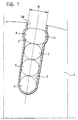
- It has already been proposed in Italian Patent Application No. TO91A000784 of 16 October 1991 in the name of the same applicant , to produce a rotor for an electrical machine, described in Figure 1, comprising a stack of
laminations 1 in the periphery of which there areradial slots 2 each of which accommodates a group of insulatedelectrical conductors 3 and has amouth portion 2a having a width W which corresponds to the diameter of aconductor 3 and accommodates the radially outermost conductor of this group. - The
mouth portion 2a of eachslot 2 hasopposite recesses 4 and the outermost conductor of eachslot 2 is deformed plastically and has a flattened portion, the opposite ends of which engage in therecesses 4, preventing theconductors 3 from escaping from theslot 2. - The
slots 2 have a constant width which is substantially equal to the diameter of theconductors 3, except in correspondence with therecesses 4. The height or depth of the slots is substantially equal to the sum of the diameters of theconductors 3 accommodated therein. - The object of the present invention is to provide a rotor of the above-mentioned type which, with respect to what has been described above, maintaining constant the diameter of the rotor, the number of the slots and the number and diameter of the conductors per slot, enables the minimum width of the part made of ferromagnetic material to be increased between slots and the width in the peripheral direction of the teeth defined between pairs of adjacent slots, ultimately obtaining - whilst the other geometrical conditions remain the same - an increase in the cross-section of the rotor which is operationally affected by the magnetic flux and thus an increase in the torque provided by the starter motor, whilst the number of revolutions remains the same.
- The present invention achieves the above objects by means of a rotor of the type specified above having the characteristics mentioned specifically in the following claims.
- Further characteristics and advantages of the present invention will become clear from the following detailed description, given purely by way of non-limiting example, with reference to the appended drawings, in which:
- Figure 1 (already described) is a partial view in cross-section of a rotor according to the prior art;
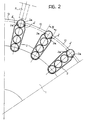
- Figure 2 is a partial view in cross-section of a rotor according to the invention in a first assembly phase; and
- Figure 3 is a partial view in cross-section of a rotor according to the invention after assembling operation.
- With reference to Figure 2, in which details which are identical or similar to those in Figure 1 are indicated by the same reference numerals, the radial slots 2 (the surfaces of which can be covered with an insulating material according to the prior art) have the
mouth portion 2a comprising two opposite projections 4' between which is a distance W substantially corresponding to the diameter of aconductor 3. - The portion of the
radial slots 2 inward of themouth portion 2a has a width in the peripheral sense which is greater than the diameter of aconductor 3; this portion decreases radially until, at the base of theslot 2, it is substantially equal to the diameter of aconductor 3. - As can be seen in Figure 2, the overall depth of the
slots 2 is less than the sum of the diameters of theconductors 3 accommodated therein (four in the case of Figures 2 and 3), for which reason a part of the outermost conductor emerges from the slot over almost half the diameter. - By means of a punch P illustrated in dashed lines in Figures 2 and 3, the
conductors 3 are plastically deformed, assuming the flattened shape of Figure 3. In this Figure, theconductors 3 are deformed progressively more markedly from the interior towards the exterior of theslots 2 and have cross-sections which are increasingly more flattened. In each slot the opposite ends of the flattened portions of the outermost conductors engage below the opposite projections 4' so as to prevent theconductors 3 emerging either in static conditions or in the more difficult dynamic conditions when the rotor is operating. - A peripheral layer of machining allowance (10 in Figure 2) can then be removed before the armature and the inductor are assembled to form the starter motor.
- By means of the characteristics described, in a rotor according to the invention, with the outer diameter of the rotor remaining the same, the minimum width of the iron between slots increases by approximately 15%, the minimum diameter on which the
conductors 3 act increases by approximately 10% and it has been confirmed in experiments that the starting torque increases by approximately 10%. - Naturally, the principles of the invention remaining the same, the forms of embodiment and details of production can be widely varied relative to what has been described and illustrated purely by way of non-limiting example, without departing from the scope of the present invention.
Claims (2)
- A rotor for an electrical machine, in particular for a direct current electric motor for starting the internal combustion engine of a motor vehicle, comprising a stack of laminations (1) in the periphery of which are arranged radial slots (2) each of which accommodates a group of insulated electrical conductors (3) and has a mouth portion (2a) comprising two opposite projections (4') between which is a distance (W) which corresponds substantially to the diameter of a conductor (3), characterised in that the radial slots (2), inwardly of the mouth portion (2a), have a width which is substantially larger than the diameter of a conductor (3), decreasing radially towards the base of the slot, where the section thereof is substantially equal to the diameter of a conductor (3); in that the conductors (3) of each slot (2) are plastically deformed and have flattened transverse portions, the opposite ends of the flattened portions of the outermost conductors (3) engaging below the opposite projections (4'), such that the conductors (3) are prevented from emerging from the slots (2); and in that the overall length of each slot (2) is less than the sum of the diameters of the non-deformed conductors (3) accommodated in the slots (2) themselves.
- A process for producing a rotor for an electrical machine, in particular for a direct current electric motor for starting an internal combustion engine for a motor vehicle, comprising the operations of:- disposing a stack of laminations (1) in the periphery of which are provided radial slots (2) for accommodating a group of insulated electrical conductors (3), each slot having a mouth portion (2a) comprising two opposite projections (4'), between which is a distance (W) which corresponds substantially to the diameter of a conductor (3); and- disposing the conductors (3) in the slots (2) of the stack of laminations (1);
the process being characterised in that the slots (2) are disposed such that, inwardly of the mouth portion (2a), they have a width which is substantially greater than the diameter of a conductor (3), decreasing radially toward the base of the slot (2) where its portion is substantially equal to the diameter of a conductor (3); in that the conductors (3) are plastically deformed in the slots (2) such that they have flattened transverse portions, the opposite ends of the flattened transverse portions of the conductors (3) engaging below the opposite projections (4') such that they prevent the conductors (3) from emerging from the slot (2); and in that the overall length of each slot (2) is less than the sum of the diameters of the non-deformed conductors (3) accommodated in the slot (2) itself.
Applications Claiming Priority (2)
| Application Number | Priority Date | Filing Date | Title |
|---|---|---|---|
| ITTO940624 | 1994-07-27 | ||
| IT94TO000624A IT1266896B1 (en) | 1994-07-27 | 1994-07-27 | ROTOR OF AN ELECTRIC MACHINE, IN PARTICULAR OF AN ELECTRIC MOTOR FOR STARTING THE INTERNAL COMBUSTION ENGINE OF A MOTOR VEHICLE AND |
Publications (2)
| Publication Number | Publication Date |
|---|---|
| EP0695019A1 true EP0695019A1 (en) | 1996-01-31 |
| EP0695019B1 EP0695019B1 (en) | 1997-09-24 |
Family
ID=11412708
Family Applications (1)
| Application Number | Title | Priority Date | Filing Date |
|---|---|---|---|
| EP95111328A Expired - Lifetime EP0695019B1 (en) | 1994-07-27 | 1995-07-19 | A rotor for an electrical machine, in particular for an electric motor for starting the internal combustion engine of a motor vehicle, and a process for its production |
Country Status (4)
| Country | Link |
|---|---|
| EP (1) | EP0695019B1 (en) |
| DE (1) | DE69500756T2 (en) |
| ES (1) | ES2109040T3 (en) |
| IT (1) | IT1266896B1 (en) |
Cited By (13)
| Publication number | Priority date | Publication date | Assignee | Title |
|---|---|---|---|---|
| WO1997045920A1 (en) * | 1996-05-29 | 1997-12-04 | Asea Brown Boveri Ab | A conductor for high-voltage windings, and a process for preparing such conductor |
| WO1997045930A1 (en) * | 1996-05-29 | 1997-12-04 | Asea Brown Boveri Ab | Conductor for high-voltage windings and a rotating electric machine comprising a winding including the conductor |
| US6226163B1 (en) | 1996-12-17 | 2001-05-01 | Asea Brown Boveri Ab | Device and method relating to protection of an object against over-currents comprising over-current reduction |
| WO2002031946A1 (en) * | 2000-10-07 | 2002-04-18 | Robert Bosch Gmbh | Rotor body and method for producing rotor bodies |
| WO2007125234A1 (en) * | 2006-05-02 | 2007-11-08 | Valeo Equipements Electriques Moteur | Method for mounting a stator coil winding in a bundle of plates |
| FR2923662A1 (en) * | 2007-11-13 | 2009-05-15 | Valeo Equip Electr Moteur | ROTATING ELECTRIC MACHINE FOR MOTOR VEHICLE. |
| CN102904361A (en) * | 2011-07-26 | 2013-01-30 | 通用汽车环球科技运作有限责任公司 | Field coil for an electric machine |
| WO2014174658A1 (en) * | 2013-04-26 | 2014-10-30 | 三菱電機株式会社 | Armature coil and manufacturing method therefor |
| US20150288231A1 (en) * | 2014-04-04 | 2015-10-08 | Solar Turbines Incorporated | Electric motor with symmetric cooling |
| WO2015159032A1 (en) * | 2014-04-17 | 2015-10-22 | Valeo Equipements Electriques Moteur | Method for the production of an electric machine stator, comprising a conductor deforming step, and corresponding stator |
| FR3020215A1 (en) * | 2014-04-17 | 2015-10-23 | Valeo Equip Electr Moteur | METHOD FOR PRODUCING AN ELECTRIC MACHINE COIL STATOR PROVIDED WITH A CONTINUOUS INSERT INSULATION AND CORRESPONDING STATOR |
| FR3023080A1 (en) * | 2014-06-30 | 2016-01-01 | Valeo Equip Electr Moteur | INDUCED ROTATING ELECTRIC MACHINE WITH OPTIMIZED NOTCH FILLING |
| EP2963773A3 (en) * | 2014-07-01 | 2016-10-12 | Victory Industrial Corporation | Vehicle alternating-current generator |
Families Citing this family (18)
| Publication number | Priority date | Publication date | Assignee | Title |
|---|---|---|---|---|
| SE9602079D0 (en) | 1996-05-29 | 1996-05-29 | Asea Brown Boveri | Rotating electric machines with magnetic circuit for high voltage and a method for manufacturing the same |
| KR100382963B1 (en) | 1996-05-29 | 2003-08-14 | 에이비비 에이비 | Rotary Electric Machine Plant |
| SE510192C2 (en) | 1996-05-29 | 1999-04-26 | Asea Brown Boveri | Procedure and switching arrangements to reduce problems with three-tier currents that may occur in alternator and motor operation of AC machines connected to three-phase distribution or transmission networks |
| SE509072C2 (en) | 1996-11-04 | 1998-11-30 | Asea Brown Boveri | Anode, anodizing process, anodized wire and use of such wire in an electrical device |
| SE510422C2 (en) | 1996-11-04 | 1999-05-25 | Asea Brown Boveri | Magnetic sheet metal core for electric machines |
| SE512917C2 (en) | 1996-11-04 | 2000-06-05 | Abb Ab | Method, apparatus and cable guide for winding an electric machine |
| SE515843C2 (en) | 1996-11-04 | 2001-10-15 | Abb Ab | Axial cooling of rotor |
| SE9704431D0 (en) | 1997-02-03 | 1997-11-28 | Asea Brown Boveri | Power control of synchronous machine |
| SE9704421D0 (en) | 1997-02-03 | 1997-11-28 | Asea Brown Boveri | Series compensation of electric alternator |
| SE508544C2 (en) | 1997-02-03 | 1998-10-12 | Asea Brown Boveri | Method and apparatus for mounting a stator winding consisting of a cable. |
| SE508543C2 (en) | 1997-02-03 | 1998-10-12 | Asea Brown Boveri | Coiling |
| SE9704422D0 (en) | 1997-02-03 | 1997-11-28 | Asea Brown Boveri | End plate |
| SE9704427D0 (en) | 1997-02-03 | 1997-11-28 | Asea Brown Boveri | Fastening device for electric rotary machines |
| SE9704423D0 (en) | 1997-02-03 | 1997-11-28 | Asea Brown Boveri | Rotary electric machine with flushing support |
| GB2331867A (en) | 1997-11-28 | 1999-06-02 | Asea Brown Boveri | Power cable termination |
| AU9362998A (en) | 1997-11-28 | 1999-06-16 | Asea Brown Boveri Ab | Method and device for controlling the magnetic flux with an auxiliary winding ina rotating high voltage electric alternating current machine |
| US6801421B1 (en) | 1998-09-29 | 2004-10-05 | Abb Ab | Switchable flux control for high power static electromagnetic devices |
| DE102018104844A1 (en) * | 2018-03-02 | 2019-09-05 | Aumann Espelkamp Gmbh | Method and device for producing an arrangement for a coil with a distributed coil winding of an electrodynamic machine, arrangement and coil |
Citations (4)
| Publication number | Priority date | Publication date | Assignee | Title |
|---|---|---|---|---|
| DE572619C (en) * | 1929-10-29 | 1933-03-18 | Bbc Brown Boveri & Cie | Method for fastening a bare short-circuit rod inserted into an open groove of a short-circuit runner |
| FR1573177A (en) * | 1968-04-11 | 1969-07-04 | ||
| FR2415385A1 (en) * | 1978-01-18 | 1979-08-17 | Bosch Gmbh Robert | ROTOR FOR AN ELECTRIC MACHINE |
| DE3347195A1 (en) * | 1982-12-27 | 1984-07-05 | Hitachi, Ltd., Tokio/Tokyo | ANCHOR FOR AN ELECTRICAL ROTATION MACHINE |
-
1994
- 1994-07-27 IT IT94TO000624A patent/IT1266896B1/en active IP Right Grant
-
1995
- 1995-07-19 DE DE69500756T patent/DE69500756T2/en not_active Expired - Lifetime
- 1995-07-19 EP EP95111328A patent/EP0695019B1/en not_active Expired - Lifetime
- 1995-07-19 ES ES95111328T patent/ES2109040T3/en not_active Expired - Lifetime
Patent Citations (4)
| Publication number | Priority date | Publication date | Assignee | Title |
|---|---|---|---|---|
| DE572619C (en) * | 1929-10-29 | 1933-03-18 | Bbc Brown Boveri & Cie | Method for fastening a bare short-circuit rod inserted into an open groove of a short-circuit runner |
| FR1573177A (en) * | 1968-04-11 | 1969-07-04 | ||
| FR2415385A1 (en) * | 1978-01-18 | 1979-08-17 | Bosch Gmbh Robert | ROTOR FOR AN ELECTRIC MACHINE |
| DE3347195A1 (en) * | 1982-12-27 | 1984-07-05 | Hitachi, Ltd., Tokio/Tokyo | ANCHOR FOR AN ELECTRICAL ROTATION MACHINE |
Non-Patent Citations (1)
| Title |
|---|
| R. KRETZCHMANN: ""Gesichtspunkte für die herstellung und auswahl von explosionsgeschützten drehstrom-asynchronmotoren"", DEUTSCHE ELEKTROTECHNIK, vol. 13, no. 5, BERLIN, pages 165 - 168 * |
Cited By (20)
| Publication number | Priority date | Publication date | Assignee | Title |
|---|---|---|---|---|
| WO1997045920A1 (en) * | 1996-05-29 | 1997-12-04 | Asea Brown Boveri Ab | A conductor for high-voltage windings, and a process for preparing such conductor |
| WO1997045930A1 (en) * | 1996-05-29 | 1997-12-04 | Asea Brown Boveri Ab | Conductor for high-voltage windings and a rotating electric machine comprising a winding including the conductor |
| US6226163B1 (en) | 1996-12-17 | 2001-05-01 | Asea Brown Boveri Ab | Device and method relating to protection of an object against over-currents comprising over-current reduction |
| WO2002031946A1 (en) * | 2000-10-07 | 2002-04-18 | Robert Bosch Gmbh | Rotor body and method for producing rotor bodies |
| WO2007125234A1 (en) * | 2006-05-02 | 2007-11-08 | Valeo Equipements Electriques Moteur | Method for mounting a stator coil winding in a bundle of plates |
| FR2900773A1 (en) * | 2006-05-02 | 2007-11-09 | Valeo Equip Electr Moteur | METHOD FOR MOUNTING A WINDING OF A STATOR WINDING IN A PACK OF SHEETS |
| FR2923662A1 (en) * | 2007-11-13 | 2009-05-15 | Valeo Equip Electr Moteur | ROTATING ELECTRIC MACHINE FOR MOTOR VEHICLE. |
| CN102904361A (en) * | 2011-07-26 | 2013-01-30 | 通用汽车环球科技运作有限责任公司 | Field coil for an electric machine |
| CN102904361B (en) * | 2011-07-26 | 2015-09-30 | 通用汽车环球科技运作有限责任公司 | For the magnet exciting coil of motor |
| WO2014174658A1 (en) * | 2013-04-26 | 2014-10-30 | 三菱電機株式会社 | Armature coil and manufacturing method therefor |
| US9960650B2 (en) | 2013-04-26 | 2018-05-01 | Mitsubishi Electric Corporation | Armature coil and method of manufacturing the same |
| US11316395B2 (en) | 2013-04-26 | 2022-04-26 | Mitsubishi Electric Corporation | Method of manufacturing armature coil |
| US10644556B2 (en) | 2013-04-26 | 2020-05-05 | Mitsubishi Electric Corporation | Method of manufacturing armature coil |
| US20150288231A1 (en) * | 2014-04-04 | 2015-10-08 | Solar Turbines Incorporated | Electric motor with symmetric cooling |
| WO2015153081A1 (en) * | 2014-04-04 | 2015-10-08 | Solar Turbines Incorporated | Electric motor with symmetric cooling |
| FR3020196A1 (en) * | 2014-04-17 | 2015-10-23 | Valeo Equip Electr Moteur | METHOD FOR PRODUCING AN ELECTRIC MACHINE STATOR COMPRISING A CONDUCTOR DEFORMATION STEP AND CORRESPONDING STATOR |
| FR3020215A1 (en) * | 2014-04-17 | 2015-10-23 | Valeo Equip Electr Moteur | METHOD FOR PRODUCING AN ELECTRIC MACHINE COIL STATOR PROVIDED WITH A CONTINUOUS INSERT INSULATION AND CORRESPONDING STATOR |
| WO2015159032A1 (en) * | 2014-04-17 | 2015-10-22 | Valeo Equipements Electriques Moteur | Method for the production of an electric machine stator, comprising a conductor deforming step, and corresponding stator |
| FR3023080A1 (en) * | 2014-06-30 | 2016-01-01 | Valeo Equip Electr Moteur | INDUCED ROTATING ELECTRIC MACHINE WITH OPTIMIZED NOTCH FILLING |
| EP2963773A3 (en) * | 2014-07-01 | 2016-10-12 | Victory Industrial Corporation | Vehicle alternating-current generator |
Also Published As
| Publication number | Publication date |
|---|---|
| IT1266896B1 (en) | 1997-01-21 |
| DE69500756D1 (en) | 1997-10-30 |
| ITTO940624A0 (en) | 1994-07-27 |
| DE69500756T2 (en) | 1998-02-05 |
| ITTO940624A1 (en) | 1996-01-27 |
| ES2109040T3 (en) | 1998-01-01 |
| EP0695019B1 (en) | 1997-09-24 |
Similar Documents
| Publication | Publication Date | Title |
|---|---|---|
| EP0695019B1 (en) | A rotor for an electrical machine, in particular for an electric motor for starting the internal combustion engine of a motor vehicle, and a process for its production | |
| US4829206A (en) | Armature for an electric rotary machine and method of manufacturing the same | |
| EP1294076B1 (en) | Stator for an alternator and method for the manufacture thereof | |
| EP0455121B1 (en) | Stator manufacturing method | |
| US6317962B1 (en) | Method for producing a stator of an alternating-current dynamo-electric machine | |
| US6858963B2 (en) | Stator winding having cascaded end loops | |
| EP1766757B1 (en) | Dynamoelectric machine stator core with mini caps | |
| US6742238B2 (en) | Flare tooth stator for an AC generator | |
| US9136746B2 (en) | Stator for electric rotating machine and method of manufacturing the same | |
| US20020130582A1 (en) | Stator for rotary machine and method of manufacturing the stator | |
| US6938323B2 (en) | Method of manufacturing stator coil of rotary electric machine | |
| JP4019951B2 (en) | Manufacturing method of winding of rotating electrical machine and processing method of winding recess | |
| EP0612139B2 (en) | Methods and apparatus for making stators for electric motors and the like, and improved terminal boards therefor | |
| US6020667A (en) | Stator bonding nib | |
| US9287741B2 (en) | Stator for rotating electric machine | |
| EP1737101B1 (en) | Rotary electric machine and manufacturing method thereof | |
| GB2394123A (en) | Stator for brushless motor | |
| US20030048032A1 (en) | Wound stator core and method of making | |
| US20040187293A1 (en) | Radial insertion of stator hairpin windings | |
| JP2977915B2 (en) | Motor armature | |
| JP3787980B2 (en) | Rotating machine armature | |
| US20050046299A1 (en) | Windings for electric machines | |
| EP1467470B1 (en) | Rotor of rotary electric machine and method of manufacturing the rotor | |
| JPH11289721A (en) | Laminated stator core and its manufacture method | |
| JP2912789B2 (en) | Abduction type induction motor stator |
Legal Events
| Date | Code | Title | Description |
|---|---|---|---|
| PUAI | Public reference made under article 153(3) epc to a published international application that has entered the european phase |
Free format text: ORIGINAL CODE: 0009012 |
|
| AK | Designated contracting states |
Kind code of ref document: A1 Designated state(s): DE ES FR GB SE |
|
| 17P | Request for examination filed |
Effective date: 19960308 |
|
| GRAG | Despatch of communication of intention to grant |
Free format text: ORIGINAL CODE: EPIDOS AGRA |
|
| 17Q | First examination report despatched |
Effective date: 19961205 |
|
| GRAH | Despatch of communication of intention to grant a patent |
Free format text: ORIGINAL CODE: EPIDOS IGRA |
|
| RAP1 | Party data changed (applicant data changed or rights of an application transferred) |
Owner name: MAGNETI MARELLI MANUFACTURING SPA |
|
| GRAH | Despatch of communication of intention to grant a patent |
Free format text: ORIGINAL CODE: EPIDOS IGRA |
|
| GRAA | (expected) grant |
Free format text: ORIGINAL CODE: 0009210 |
|
| AK | Designated contracting states |
Kind code of ref document: B1 Designated state(s): DE ES FR GB SE |
|
| REF | Corresponds to: |
Ref document number: 69500756 Country of ref document: DE Date of ref document: 19971030 |
|
| REG | Reference to a national code |
Ref country code: ES Ref legal event code: FG2A Ref document number: 2109040 Country of ref document: ES Kind code of ref document: T3 |
|
| ET | Fr: translation filed | ||
| PLBE | No opposition filed within time limit |
Free format text: ORIGINAL CODE: 0009261 |
|
| STAA | Information on the status of an ep patent application or granted ep patent |
Free format text: STATUS: NO OPPOSITION FILED WITHIN TIME LIMIT |
|
| 26N | No opposition filed | ||
| REG | Reference to a national code |
Ref country code: GB Ref legal event code: IF02 |
|
| PGFP | Annual fee paid to national office [announced via postgrant information from national office to epo] |
Ref country code: DE Payment date: 20100723 Year of fee payment: 16 |
|
| PGFP | Annual fee paid to national office [announced via postgrant information from national office to epo] |
Ref country code: GB Payment date: 20110721 Year of fee payment: 17 Ref country code: SE Payment date: 20110722 Year of fee payment: 17 Ref country code: FR Payment date: 20110810 Year of fee payment: 17 Ref country code: ES Payment date: 20110713 Year of fee payment: 17 |
|
| REG | Reference to a national code |
Ref country code: SE Ref legal event code: EUG |
|
| GBPC | Gb: european patent ceased through non-payment of renewal fee |
Effective date: 20120719 |
|
| REG | Reference to a national code |
Ref country code: FR Ref legal event code: ST Effective date: 20130329 |
|
| PG25 | Lapsed in a contracting state [announced via postgrant information from national office to epo] |
Ref country code: FR Free format text: LAPSE BECAUSE OF NON-PAYMENT OF DUE FEES Effective date: 20120731 Ref country code: GB Free format text: LAPSE BECAUSE OF NON-PAYMENT OF DUE FEES Effective date: 20120719 Ref country code: SE Free format text: LAPSE BECAUSE OF NON-PAYMENT OF DUE FEES Effective date: 20120720 Ref country code: DE Free format text: LAPSE BECAUSE OF NON-PAYMENT OF DUE FEES Effective date: 20130201 |
|
| REG | Reference to a national code |
Ref country code: DE Ref legal event code: R119 Ref document number: 69500756 Country of ref document: DE Effective date: 20130201 |
|
| REG | Reference to a national code |
Ref country code: ES Ref legal event code: FD2A Effective date: 20131022 |
|
| PG25 | Lapsed in a contracting state [announced via postgrant information from national office to epo] |
Ref country code: ES Free format text: LAPSE BECAUSE OF NON-PAYMENT OF DUE FEES Effective date: 20120720 |