EP0694475B1 - Package-forming equipment - Google Patents
Package-forming equipment Download PDFInfo
- Publication number
- EP0694475B1 EP0694475B1 EP95111179A EP95111179A EP0694475B1 EP 0694475 B1 EP0694475 B1 EP 0694475B1 EP 95111179 A EP95111179 A EP 95111179A EP 95111179 A EP95111179 A EP 95111179A EP 0694475 B1 EP0694475 B1 EP 0694475B1
- Authority
- EP
- European Patent Office
- Prior art keywords
- conveyor means
- wrappers
- cells
- elongate elements
- equipment according
- Prior art date
- Legal status (The legal status is an assumption and is not a legal conclusion. Google has not performed a legal analysis and makes no representation as to the accuracy of the status listed.)
- Expired - Lifetime
Links
- 238000009825 accumulation Methods 0.000 claims abstract description 10
- 239000000463 material Substances 0.000 claims abstract description 3
- 230000000694 effects Effects 0.000 claims description 6
- 238000004519 manufacturing process Methods 0.000 claims description 3
- 230000007480 spreading Effects 0.000 claims description 3
- 230000000295 complement effect Effects 0.000 claims description 2
- 230000000149 penetrating effect Effects 0.000 claims 1
- 244000299461 Theobroma cacao Species 0.000 abstract description 3
- 235000019219 chocolate Nutrition 0.000 abstract description 3
- 210000003128 head Anatomy 0.000 description 10
- 230000009471 action Effects 0.000 description 7
- 235000013305 food Nutrition 0.000 description 6
- 238000007493 shaping process Methods 0.000 description 3
- 241000196324 Embryophyta Species 0.000 description 2
- 230000008021 deposition Effects 0.000 description 2
- 238000004806 packaging method and process Methods 0.000 description 2
- 229920000298 Cellophane Polymers 0.000 description 1
- 238000005452 bending Methods 0.000 description 1
- 230000008901 benefit Effects 0.000 description 1
- 230000015572 biosynthetic process Effects 0.000 description 1
- 235000015895 biscuits Nutrition 0.000 description 1
- 125000004122 cyclic group Chemical group 0.000 description 1
- 238000011161 development Methods 0.000 description 1
- 230000018109 developmental process Effects 0.000 description 1
- 210000000744 eyelid Anatomy 0.000 description 1
- 210000000887 face Anatomy 0.000 description 1
- 230000005484 gravity Effects 0.000 description 1
- 238000003780 insertion Methods 0.000 description 1
- 230000037431 insertion Effects 0.000 description 1
- 230000002452 interceptive effect Effects 0.000 description 1
- 230000007246 mechanism Effects 0.000 description 1
- ORQBXQOJMQIAOY-UHFFFAOYSA-N nobelium Chemical compound [No] ORQBXQOJMQIAOY-UHFFFAOYSA-N 0.000 description 1
- 238000007789 sealing Methods 0.000 description 1
Images


Classifications
-
- B—PERFORMING OPERATIONS; TRANSPORTING
- B65—CONVEYING; PACKING; STORING; HANDLING THIN OR FILAMENTARY MATERIAL
- B65B—MACHINES, APPARATUS OR DEVICES FOR, OR METHODS OF, PACKAGING ARTICLES OR MATERIALS; UNPACKING
- B65B5/00—Packaging individual articles in containers or receptacles, e.g. bags, sacks, boxes, cartons, cans, jars
- B65B5/02—Machines characterised by incorporation of means for making the containers or receptacles
- B65B5/024—Machines characterised by incorporation of means for making the containers or receptacles for making containers from preformed blanks
-
- B—PERFORMING OPERATIONS; TRANSPORTING
- B65—CONVEYING; PACKING; STORING; HANDLING THIN OR FILAMENTARY MATERIAL
- B65B—MACHINES, APPARATUS OR DEVICES FOR, OR METHODS OF, PACKAGING ARTICLES OR MATERIALS; UNPACKING
- B65B19/00—Packaging rod-shaped or tubular articles susceptible to damage by abrasion or pressure, e.g. cigarettes, cigars, macaroni, spaghetti, drinking straws or welding electrodes
- B65B19/34—Packaging other rod-shaped articles, e.g. sausages, macaroni, spaghetti, drinking straws, welding electrodes
-
- B—PERFORMING OPERATIONS; TRANSPORTING
- B65—CONVEYING; PACKING; STORING; HANDLING THIN OR FILAMENTARY MATERIAL
- B65B—MACHINES, APPARATUS OR DEVICES FOR, OR METHODS OF, PACKAGING ARTICLES OR MATERIALS; UNPACKING
- B65B25/00—Packaging other articles presenting special problems
- B65B25/005—Packaging other articles presenting special problems packaging of confectionery
-
- B—PERFORMING OPERATIONS; TRANSPORTING
- B65—CONVEYING; PACKING; STORING; HANDLING THIN OR FILAMENTARY MATERIAL
- B65D—CONTAINERS FOR STORAGE OR TRANSPORT OF ARTICLES OR MATERIALS, e.g. BAGS, BARRELS, BOTTLES, BOXES, CANS, CARTONS, CRATES, DRUMS, JARS, TANKS, HOPPERS, FORWARDING CONTAINERS; ACCESSORIES, CLOSURES, OR FITTINGS THEREFOR; PACKAGING ELEMENTS; PACKAGES
- B65D5/00—Rigid or semi-rigid containers of polygonal cross-section, e.g. boxes, cartons or trays, formed by folding or erecting one or more blanks made of paper
- B65D5/20—Rigid or semi-rigid containers of polygonal cross-section, e.g. boxes, cartons or trays, formed by folding or erecting one or more blanks made of paper by folding-up portions connected to a central panel from all sides to form a container body, e.g. of tray-like form
- B65D5/2014—Rigid or semi-rigid containers of polygonal cross-section, e.g. boxes, cartons or trays, formed by folding or erecting one or more blanks made of paper by folding-up portions connected to a central panel from all sides to form a container body, e.g. of tray-like form the central panel having a non rectangular shape
- B65D5/2019—Rigid or semi-rigid containers of polygonal cross-section, e.g. boxes, cartons or trays, formed by folding or erecting one or more blanks made of paper by folding-up portions connected to a central panel from all sides to form a container body, e.g. of tray-like form the central panel having a non rectangular shape with at least partially curved edges or the like
-
- B—PERFORMING OPERATIONS; TRANSPORTING
- B65—CONVEYING; PACKING; STORING; HANDLING THIN OR FILAMENTARY MATERIAL
- B65D—CONTAINERS FOR STORAGE OR TRANSPORT OF ARTICLES OR MATERIALS, e.g. BAGS, BARRELS, BOTTLES, BOXES, CANS, CARTONS, CRATES, DRUMS, JARS, TANKS, HOPPERS, FORWARDING CONTAINERS; ACCESSORIES, CLOSURES, OR FITTINGS THEREFOR; PACKAGING ELEMENTS; PACKAGES
- B65D5/00—Rigid or semi-rigid containers of polygonal cross-section, e.g. boxes, cartons or trays, formed by folding or erecting one or more blanks made of paper
- B65D5/20—Rigid or semi-rigid containers of polygonal cross-section, e.g. boxes, cartons or trays, formed by folding or erecting one or more blanks made of paper by folding-up portions connected to a central panel from all sides to form a container body, e.g. of tray-like form
- B65D5/2038—Rigid or semi-rigid containers of polygonal cross-section, e.g. boxes, cartons or trays, formed by folding or erecting one or more blanks made of paper by folding-up portions connected to a central panel from all sides to form a container body, e.g. of tray-like form at least two opposed folded-up portions having a non-rectangular shape
-
- B—PERFORMING OPERATIONS; TRANSPORTING
- B65—CONVEYING; PACKING; STORING; HANDLING THIN OR FILAMENTARY MATERIAL
- B65D—CONTAINERS FOR STORAGE OR TRANSPORT OF ARTICLES OR MATERIALS, e.g. BAGS, BARRELS, BOTTLES, BOXES, CANS, CARTONS, CRATES, DRUMS, JARS, TANKS, HOPPERS, FORWARDING CONTAINERS; ACCESSORIES, CLOSURES, OR FITTINGS THEREFOR; PACKAGING ELEMENTS; PACKAGES
- B65D5/00—Rigid or semi-rigid containers of polygonal cross-section, e.g. boxes, cartons or trays, formed by folding or erecting one or more blanks made of paper
- B65D5/20—Rigid or semi-rigid containers of polygonal cross-section, e.g. boxes, cartons or trays, formed by folding or erecting one or more blanks made of paper by folding-up portions connected to a central panel from all sides to form a container body, e.g. of tray-like form
- B65D5/28—Rigid or semi-rigid containers of polygonal cross-section, e.g. boxes, cartons or trays, formed by folding or erecting one or more blanks made of paper by folding-up portions connected to a central panel from all sides to form a container body, e.g. of tray-like form with extensions of sides permanently secured to adjacent sides, with sides permanently secured together by adhesive strips, or with sides held in place solely by rigidity of material
Definitions
- the present invention relates to equipment for forming packages comprising elongate elements inserted in generally boat-shaped wrappers.
- the wrappers I are taken from the store 3 and inserted in the cells 7 of the conveyor 4 by a handling robot 100.
- This robot has an operative head or hand 101 ( Figure 1) including one or more (for example three) pick-up elements 102 which can act between the store 3 and the conveyor 4.
- a take-up member 106 operates in correspondence with each outlet aperture of the store 3 and can be oriented selectively between:
- the parts 104 are U-shaped in cross sectional profile, this shape being approximately complementary to the channel shape which it is wished to impart to the central portion A of the wrappers I.
- the length of the parts 104 is just slightly less than the distance between the mutually facing apex portions of the eyelid-shaped parts B2 and C2.
- the alignment and accumulation stage 14 is also constituted by a known device: this may be constituted, for example, by equipment substantially like that described in the document DE-A-37 24 839.
Landscapes
- Engineering & Computer Science (AREA)
- Mechanical Engineering (AREA)
- Container Filling Or Packaging Operations (AREA)
- Control And Other Processes For Unpacking Of Materials (AREA)
- Containers And Plastic Fillers For Packaging (AREA)
- Packages (AREA)
- Auxiliary Devices For And Details Of Packaging Control (AREA)
- Basic Packing Technique (AREA)
Abstract
Description
- The present invention relates to equipment for forming packages comprising elongate elements inserted in generally boat-shaped wrappers.
- The invention has been developed with particular but not exclusive attention to its possible use for the formation of packages of the type forming the subject of International Model DM/022926.
- This package is constituted essentially by a wrapper defined by a channel portion closed at its two ends by eyelid-shaped end walls and intended to receive a plurality of elongate elements. These latter may be constituted by the products themselves (for example food products such as breadsticks, elongate biscuits, possibly covered in chocolate or other food products, sticks of food products, etc, wrapped in respective wrappers) or - as in the case of the package which is the subject of the International Model cited - by sub-elements of the package such as, for example, tubular wrappers (possibly of the flow-pack type) including a plurality of food products such as spherical pralines.
- In the manufacture of packages of the type specified above, it is necessary to take account of two basic requirements, that is to say:
- the outer wrapper of the package is usually provided in the form of a cardboard product constituted by a rectangular sheet of card (possibly corrugated card) having two end appendages folded and partly glued to the card itself with pre-blanked parts for forming the eyelid-shaped end walls: the cardboard product in question must then be formed to give it the required boat shape for receiving the elongate elements, and
- these elements must be located in the wrapper in a centred position of mutual alignment, avoiding any end appendages (such as the end tabs of flow-packs) from interfering with their introduction into the wrapper.
- In addition it must not be forgotten that the shaping of the wrapper and filling thereof must be capable of being carried out automatically on an industrial scale, at the very high rates typical of current production processes.
- The object of the present invention is to provide equipment which is able to satisfy the requirements mentioned above in an excellent manner.
- According to the present invention, this object is achieved by equipment as defined in
Claim 1. Advantageous developments of the invention form the subject of Claims 2 to 10. - The invention will now be described, purely by way of non-limitative example, with reference to the appended drawings, in which:
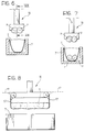
- Figure 1 is a general perspective view of equipment operating according to the invention,
- Figure 2 illustrates schematically the characteristics of part of a package formed by the equipment of Figure 1,
- Figures 3 and 4 illustrate the structure and characteristics of part of the equipment of Figure 1 in greater detail and in two successive stages of operation,
- Figure 5 illustrates the effect of the operation of the parts of the equipment illustrated in Figures 3 and 4 on the part of the package illustrated in Figure 2,
- Figures 6 and 7 illustrate two successive stages in the operation of a further part of the equipment of Figure 1,
- Figure 8 illustrates schematically the structural characteristics of the part of the apparatus the operation of which is illustrated in Figures 6 and 7 in a view corresponding approximately to a section taken on the line VIII-VIII of Figure 6, and
- Figure 9 illustrates the effect of the operation of the parts of the apparatus illustrated in Figures 6-8 on the combination of parts illustrated in Figure 5.
- In Figure 1, automatic packaging equipment is generally indicated 1 which can be used for example to form packages such as that forming the subject of International Model DM/022926 already mentioned in the introduction to the present specification.
- The
apparatus 1 is constituted essentially by several operative parts or sections in succession, that is to say, - a wrapper-forming section 2 in which the outer wrappers I of the packages, held in the form of blanks (which will be described more fully below with reference to Figure 2) in a store 3, are formed into the general configuration of a boat and inserted in respective receiving cells in a longitudinal
main conveyor 4 which passes through theequipment 1; - a
filling station 5 for the loading of the elongate elements P, in which these elements (coming from a forming station such as, for example, a flow-pack wrapping machine in which individual products, such as pralines, chocolates, etc., are inserted in elongate envelopes closed by end tabs) are placed in the wrappers I in the cells of theconveyor 4; and - an
output station 6 at which the packages constituted by the outer wrappers I each filled with a given number of elements P are completed by, for example, the application of a tubular closure band. - Figure 2 illustrates in greater detail the structure of the outer wrappers I intended to be packaged in the
equipment 1 in the form in which they are placed in the store 3 prior to insertion in the cells (usually defined by boxes 7) of theconveyor 4. - As they are presented in the form of cardboard blanks (manufactured and prepared according to known criteria not themselves relevant to an understanding of the present invention), the wrappers I are constituted each essentially by a sheet of card, usually corrugated with longitudinal channels, including a substantially flat central portion A of rectangular shape and two end flaps B and C folded over the central portion A and partly glued to it.
- More precisely, each flap B and C can be seen to be constituted by a "fixed" part B1, C1 of generally U-shape, glued to the central portion A, and a "movable" part B2, C2 of generally eyelid shape, not glued and hence raisable from the central part A.
- Between the two parts B1, B2 and C1, C2 respectively of each flap B and C is a line of punched holes for forming a zone in which the card can easily be bent. As stated above, this card is preferably constituted by corrugated card with the corrugations oriented so that their channels extend in the direction of the main longitudinal axis of the wrapper I, not only in the central portion A (particularly on the lower face - not visible - with reference to the point of view of Figure 2) but also in the flaps B, C.
- The corrugations give the wrapper I a certain longitudinal strength accompanied by a facility to bend in the direction perpendicular to the length of the channels of the corrugations. All this facilitates the possibility of forming the central portion A into a generally channel shape and, together with the upward bending of the eyelid-shaped parts B2, C2 of the flaps B, C, giving the wrapper I a generally boat shape.
- Figures 3 and 4 illustrate in greater detail how this result is achieved by the
equipment 1 of the invention. - The wrappers I are taken from the store 3 and inserted in the
cells 7 of theconveyor 4 by ahandling robot 100. This robot has an operative head or hand 101 (Figure 1) including one or more (for example three) pick-up elements 102 which can act between the store 3 and theconveyor 4. - The conveyor in question may be an ordinary conveyor used in plants for the automatic handling of food products, in which each
cell 7 is constituted, for example, by a channel-shaped body of rectangular or square section which can receive - in sufficiently tight conditions - a respective boat shaped wrapper I. - Each of the
cells 7 is connected to the other cells of theconveyor 4 by drive means of the conveyor, such as, a motor drivencentral belt 8 to which thecells 7 are fixed (by known means) so as to cause thecells 7 to advance in the general direction of the arrows shown in Figures 1 and 3. - In the preferred embodiment illustrated in the drawings, the head or
hand 101 of therobot 100 is in the general form of a rake with the pick-up elements 102 mounted on acommon structure 103 exactly like the teeth or prongs of a rake. - The
structure 103 may be constituted simply by an elongate plate or rod which extends in the direction of theconveyor 4 in front of the store 3. As shown in the drawings, each pick-up element 102 is generally T-shaped with a stem which carries anactive part 104 constituting the head of the T-shape extending perpendicular to the length of thestructure 103. - In the embodiment illustrated, the store 3 includes three outlet apertures (or take-up positions for the wrappers) that is, the same number as the number of pick-
up elements 102 of the head orhand 101 of therobot 100. The wrappers I are accumulated in the store 3 in rows (one for each outlet aperture) orientated vertically in a plane parallel to the direction of theconveyor 4, with their direction of major extent oriented vertically. - A take-
up member 106, of known type, operates in correspondence with each outlet aperture of the store 3 and can be oriented selectively between: - a rest position (illustrated in full outline in Figure 1) in which the
member 106 bears against the row of wrappers I which advance towards the outlet aperture (under gravity or under the action of pusher means not illustrated), and - a delivery position (illustrated schematically in broken outline in Figure 1) in which the
member 106 is tipped forwardly towards therobot 100 into a horizontal position, carrying with it (for example as a result of a hooking action or by virtue of the presence of a suction gripper element, such as a suction cup, not visible in the drawings) the first wrapper I in the row, presenting it in a position for gripping up by therobot 100. - This latter (and in particular the head or hand 101) is in turn reciprocable between:
- a pick-up position, in which the or each of the
active parts 104 is located above a wrapper I carried by therespective member 106, captures it and retains it against itself by virtue of the action of the pick-up means, such assuction cups 105 connected in known manner to a low pressure (vacuum) source, not explicitly shown in the drawings, and - a loading position in which the head or
hand 101, with its respective pick-up elements 102 carrying the wrappers I attached to theparts 104, is located above theconveyor 4 momentarily stopped or slowed, so as to place each wrapper I taken from magazine 3 over the aperture of arespective cell 7 as shown schematically in Figure 3. - The same drawing shows clearly how the
active parts 104 and thecells 7 of theconveyor 4 have approximately corresponding dimensions so that they are of generally male-female configuration. This enables theparts 104 to enter thecorresponding cells 7 from above (as a result of a vertical downward movement of the arm of therobot 100 which carries the head or hand 101), forcing the wrappers I into them. - From an observation of Figure 3, it may also be appreciated that the
parts 104 are U-shaped in cross sectional profile, this shape being approximately complementary to the channel shape which it is wished to impart to the central portion A of the wrappers I. Moreover, the length of the parts 104 (measured between theflat end faces 104a in the direction of longitudinal extent of the blanks I, which direction obviously also corresponds to the direction of alignment of thesuction cups 105 and to the direction of the major axes of thecells 7, which is perpendicular to the direction of advance of the conveyor 4) is just slightly less than the distance between the mutually facing apex portions of the eyelid-shaped parts B2 and C2. - This enables two
spreader flaps 11 to be provided, one at each end of the active part 104 (that is, in correspondence with thefaces 104a). - As can best be deduced from a comparison of Figures 3 and 4, each spreader flap is mounted on the
part 104 so as to be pivotable about a respective horizontal axis X11, defined, for example, byhinge systems 11a. The axes X11 are thus parallel to the general direction of advance of theconveyor 4. - The pivoting of the
flaps 11 about the axis X11 is driven by known mechanisms (for example by respective fluid-actuated pushers not visible in the drawings) mounted within thepart 104 and each acting on the face of therespective flap 11 facing into thepart 104. - As a result of the vertical movement of the arm of the
robot 100, the or eachpart 104 mounted on the head orhand 101 can move downwardly relative to theconveyor 4 so as to insert the or each wrapper I in therespective cell 7 of theconveyor 4. - When a wrapper I taken from the store 3 is placed on the opening of a
respective cell 7, the arm of therobot 100 is lowered (under the action of drive means of known type not shown explicitly in the drawings) so as to force the wrapper I, carried by thepart 104 as a result of the action of thesuction cups 105, into therespective cell 7. At the same time (see the sequence of Figures 3 and 4) theflaps 11 are pivoted about their respective axes X11 in the spreading sense as illustrated in Figure 4. - The lowering of the
part 104 into thecell 7 beneath it serves to force the central portion A of the wrapper I into thecell 7 so as to give it the desired channel shape. At the same time, the diverging of theflaps 11 causes the eyelid-shaped parts B2, C2 to be spread apart and thus raised so as to form the end parts of the wrapper I. Once it has been inserted fully into itscell 7, this wrapper is formed (erected) into its desired boat shape, illustrated in Figure 5. - At this point the
suction cups 105 may be deactivated and the head orhand 101 returned upwardly so as to be ready for a repetition of the cycle of picking up, shaping and loading the wrappers I into thecells 7, as described above, while each wrapper I is held securely in itscell 7 for example by retaining teeth 7a along the longitudinal edges of the opening of thecell 7. - As has been seen, the head or
hand 101 preferably carriesseveral elements 102 with their respective parts 104 (for example three). The action of picking up, shaping and loading into thecells 7 is thus carried out simultaneously on a group of wrappers I (for example three wrappers I) taken from the store 3 at the same time. - As a result of the advance of the
conveyor 4, the wrappers I are carried to thefilling station 5, being advanced in the direction of their widths, that is, with their longer dimension perpendicular to the direction of advance (Figure 1). - The filling station is constituted by several operative stages, that is to say:
- a
conveyor 13 which supplies the elements P to theconveyor 4, advancing them in the direction of their lengths (that is with their longer dimension aligned with the direction of advance), - an alignment and
accumulation stage 14 located downstream of theconveyor 13 for forming a buffer or accumulation of elements P, and - a further robot or
handler 15 for taking the individual elements P from theaccumulation stage 14 and placing them in the wrappers I in thecells 7. - The
conveyor 13, like theconveyor 4, is an ordinary conveyor device (for example with motor-driven belts of the type currently used in automatic packaging plants for food products). - The alignment and
accumulation stage 14 is also constituted by a known device: this may be constituted, for example, by equipment substantially like that described in the document DE-A-37 24 839. - The
handler 15 is constituted essentially by a robot having one ormore grippers 16 which can effect generally vertical and translational movements in a cyclic sequence of steps including: - lowering over one or more accumulation cells of the
stage 14 with the take up of a corresponding number (for example a pair) of elements P, - raising with subsequent translational movement to a position above the
conveyor 4, - lowering towards the
conveyor 4 with the deposition of the elongate elements P taken from thestage 14 into the wrapper I in theunderlying cell 7, and - return travel to the
accumulation stage 14 to take up a new group of elongate elements P. - The sequence shown in Figures 6 and 7 shows how the (or each) gripper or
hand 16 of thehandler 15 may be arranged to grasp a pair of elongate elements P simultaneously and then deposit them in the wrapper I (which is then filled with a predetermined number of pairs - for example two - of elongate elements P). - The side view of Figure 8 shows how, as is preferred, the action of the
hand 16 in gripping the elements P is exerted not (or at least not exclusively) on the sides of the elements P but also (although not exclusively) on the ends of the elements P. This fact is illustrated clearly by the position of the gripper flaps 17 of thehand 16. In Figure 8 these flaps are shown in full outline in a closed position in which they grip the elements P and in broken outline in an open position in which they are disengaged from, and hence release, the elements P. - As stated above, the elongate elements P are preferably constituted by individual flow-pack wrappers having closure and sealing tabs at their ends.
- The fact that the gripper flaps 17 of the
hand 16 act on these ends has the advantage of flattening the tabs of the flow-pack against the body of the package itself as a result of the gripping of the elements P by thegripper hand 16. When the elements P are deposited in the wrapper I, these tabs thus cannot interfere with the end walls of the wrapper I defined by the eyelid-shaped parts B2 and C2. The correct and regular deposition of the elements P within the wrapper I is thus ensured. - Once the filling with the elements P is completed, the completed packages (Figure 9) are advanced towards the
station 6. Here each package is removed from itscell 7 by alateral pusher member 18 which moves to and fro, the respective pusher elements 19 entering thecells 7 longitudinally to push the packages out longitudinally and transfer them to anoutput conveyor 20 alongside the downstream end of theconveyor 4. Theconveyor 20 carries the packages to a banding machine 21 (of known type) in which anannular band 22 of sheet material (cellophane or the like), taken from a reel indicated 23, is applied around each package. As stated, the operating criteria and details of such machines for applying bands should be considered as known per se and such as not to require a description herein. - Naturally, the principle of the invention remaining the same, the constructional details and forms of embodiment may be varied widely with respect to those described and illustrated without thereby departing from the scope of the present invention as defined in the appended claims.
Claims (10)
- Equipment for forming packages comprising elongate elements (P) inserted in generally boat-shaped wrappers (I), comprising:- a source (3) for supplying the wrappers (I) in the form of blanks including a substantially flat central portion (A) with end flaps (B,C) folded onto the central portion (A) with respective eyelid-shaped portions (B2,C2) which can be raised up from the central portion (A),- conveyor means (4) including channel shaped cells (7) for receiving the wrappers (I) coming from the source (3),- forming means (104,11) which can act on the blanks coming from the source (3) when each blank is placed on the opening of a respective cell (7) of the conveyor means (4); the forming means (104,11) being capable of entering the cells (7) of the conveyor means (4) so as to form the central portion (A) of each blank located on a respective one of the cells (7) into a generally channel shape as well as to effect a spreading movement (11) in the longitudinal direction of the channel shape so as to lift up the eyelid-shaped portions (B2,C2) of the end flaps (B,C) from the central portion (A) and spread the eyelid-shaped portions (B2,C2) apart so that they form respective end walls of a respective one of the generally boat-shaped packages (I),- further conveyor means (13) downstream of the forming means in the general direction of advance of the conveyor means, for advancing the elongate elements (P) towards the conveyor means (4) after the conveyor means (4) have received the wrappers (I) in the cells (7), and- inserter means (14-17) acting between the further conveyor means (13) and the conveyor means (4) for selectively placing the elongate elements (P) in the generally boat-shaped wrappers (I) in the respective cells (7) of the conveyor means (4).
- Equipment according to Claim 1, characterised in that it further includes, downstream of the inserter means (14-17) in the general direction of advance of the conveyor means (4), a banding station (6) in which each of the packages is completed by the application of a tubular band (22) of sheet material.
- Equipment according to Claim 1 or Claim 2, characterised in that the forming means comprise:- an active part (104) having a profile complementary to that of the cell (7), which can hold a respective blank (I) on to itself (105) and force it into a respective cell (7), and- a pair of appendages (11) connected to the active part (104) in opposing positions which, in use, face the eyelid-shaped portions (B2, C2) of the respective blank (I); the appendages (11) being able to effect a generally spreading movement between a closed position of engagement with the eyelid-shaped portions (B2,C2) and an open position in which the eyelid-shaped portions (B2,C2) are raised from the central portion (A) to form respective end walls of the wrappers (I).
- Equipment according to Claim 3, characterised in that the active part (104) has associated suction gripper means (105) for holding the blank (I) to the active part (104).
- Equipment according to any one of the preceding claims, characterised in that the forming means (104, 11) are attached to movable apparatus (101) which can move upwards and downwards relative to the cells (7) of the conveyor means (4); the downward movement causing the forming means (104,11) to enter the cells (7).
- Equipment according to any one of the preceding claims, characterised in that the forming means (104, 11) are attached to movable apparatus (101) which can reciprocate between a pick-up position, in which the forming means (104,11) cooperate with the source (3) in order to pick up the wrappers in the form of blanks (I) selectively from the source (3), and a loading position, in which the forming means (104,11) are aligned with the conveyor means (4) ready to effect a penetrating movement into the cell (7).
- Equipment according to any one of the preceding claims, characterised in that an accumulation stage (14) for the accumulation of the elongate elements (P) is inserted between the further conveyor means (13) and the inserter means (14-17).
- Equipment according to any one of the preceding claims, characterised in that the further conveyor means (13) advance the elongate elements (P) in the direction of their lengths while the conveyor means (4) advance the wrappers (I) received in the respective cells (7) in the direction of their widths.
- Equipment according to any one of the preceding claims, characterised in that the inserter means (14 to 17) include a pick-up element (16,17) which can grip the elongate elements (P) coming from the further conveyor means (13) in order to insert them in the wrappers (I) in the cells (7) of the conveyor means (4).
- Equipment according to any one of the preceding claims, for the manufacture of packages in which the elongate elements (P) are constituted by package elements having end tabs, characterised in that the pick-up element (16,17) operates primarily by gripping the elongate elements (P) by the end tabs, folding the tabs themselves against the respective elongate element (P).
Priority Applications (1)
| Application Number | Priority Date | Filing Date | Title |
|---|---|---|---|
| SI9530010T SI0694475T1 (en) | 1994-07-27 | 1995-07-17 | Package-forming equipment |
Applications Claiming Priority (2)
| Application Number | Priority Date | Filing Date | Title |
|---|---|---|---|
| CH02367/94A CH689016A5 (en) | 1994-07-27 | 1994-07-27 | Apparatus for forming packs. |
| CH2367/94 | 1994-07-27 |
Publications (2)
| Publication Number | Publication Date |
|---|---|
| EP0694475A1 EP0694475A1 (en) | 1996-01-31 |
| EP0694475B1 true EP0694475B1 (en) | 1997-05-02 |
Family
ID=4232131
Family Applications (1)
| Application Number | Title | Priority Date | Filing Date |
|---|---|---|---|
| EP95111179A Expired - Lifetime EP0694475B1 (en) | 1994-07-27 | 1995-07-17 | Package-forming equipment |
Country Status (8)
| Country | Link |
|---|---|
| EP (1) | EP0694475B1 (en) |
| AT (1) | ATE152410T1 (en) |
| CH (1) | CH689016A5 (en) |
| DE (1) | DE69500269T2 (en) |
| DK (1) | DK0694475T3 (en) |
| ES (1) | ES2103620T3 (en) |
| GR (1) | GR3023980T3 (en) |
| SI (1) | SI0694475T1 (en) |
Family Cites Families (2)
| Publication number | Priority date | Publication date | Assignee | Title |
|---|---|---|---|---|
| CH453188A (en) * | 1967-06-23 | 1968-06-14 | Friedrich Ing Banz | Method for packaging counted, rod-shaped articles |
| DE3724839A1 (en) | 1987-07-27 | 1989-02-09 | Schubert Gerhard Gmbh | Packaging, collecting and storing machine |
-
1994
- 1994-07-27 CH CH02367/94A patent/CH689016A5/en not_active IP Right Cessation
-
1995
- 1995-07-17 DK DK95111179.8T patent/DK0694475T3/en active
- 1995-07-17 ES ES95111179T patent/ES2103620T3/en not_active Expired - Lifetime
- 1995-07-17 AT AT95111179T patent/ATE152410T1/en not_active IP Right Cessation
- 1995-07-17 EP EP95111179A patent/EP0694475B1/en not_active Expired - Lifetime
- 1995-07-17 SI SI9530010T patent/SI0694475T1/en unknown
- 1995-07-17 DE DE69500269T patent/DE69500269T2/en not_active Expired - Fee Related
-
1997
- 1997-07-02 GR GR970401633T patent/GR3023980T3/en unknown
Also Published As
| Publication number | Publication date |
|---|---|
| ES2103620T3 (en) | 1997-09-16 |
| DE69500269T2 (en) | 1997-08-28 |
| DE69500269D1 (en) | 1997-06-05 |
| EP0694475A1 (en) | 1996-01-31 |
| CH689016A5 (en) | 1998-07-31 |
| GR3023980T3 (en) | 1997-10-31 |
| SI0694475T1 (en) | 1998-02-28 |
| DK0694475T3 (en) | 1997-10-13 |
| ATE152410T1 (en) | 1997-05-15 |
Similar Documents
| Publication | Publication Date | Title |
|---|---|---|
| EP0197368B1 (en) | Method and apparatus for packaging cigarettes in particular | |
| US5027586A (en) | Side loading machine | |
| US4713928A (en) | Automatic packaging machine for closing over filled boxes | |
| JPH0656105A (en) | Device for manufacturing carton | |
| ITMI960641A1 (en) | PACKAGING FOR SINGLE PACKAGES, AS WELL AS PROCEDURE AND DEVICE TO PRODUCE IT | |
| US4907397A (en) | Shelf packer | |
| JP3628086B2 (en) | Method for transporting snack confectionery packaging bag and method for transporting and packing snack confectionery packaging bag | |
| IT9003542A1 (en) | DEVICE FOR THE TRANSFORMATION OF A TUBULAR DIE CUT INTO A CORRESPONDENT CARTON. | |
| US5706636A (en) | Envelope-stuffing device | |
| EP1314645B1 (en) | Method and device for transferring articles, in particular blister packs, to the feeding line of a packaging machine | |
| CH714657B1 (en) | Unit and method for arranging objects in boxes. | |
| EP0694475A1 (en) | Package-forming equipment | |
| US20030079961A1 (en) | Process and apparatus for depositing products in a defined manner from a compartment-containing chain | |
| US4499704A (en) | Corrugated box forming, loading and sealing machine | |
| GB948261A (en) | Apparatus for depanning, slicing, dispensing and packaging baked goods | |
| WO2025190918A1 (en) | Unit for setting up tools for packaging fruit and vegetable products, and related method | |
| JP2002308238A (en) | Article take-out device | |
| WO1999016670A9 (en) | Bagger method and apparatus | |
| EP0092402A2 (en) | Improved carton packing apparatus | |
| EP0712783A1 (en) | Automatic modular packaging machine | |
| EP0761537B1 (en) | Method and unit for packing products | |
| EP1094005B1 (en) | Process and apparatus for packaging a pasty food product | |
| DE202010013645U1 (en) | Device for unpacking consumer packs for bakery products | |
| JP3764548B2 (en) | Automatic boxing method and apparatus | |
| EP0077302B1 (en) | Method and machine for packaging several individually wrapped food products |
Legal Events
| Date | Code | Title | Description |
|---|---|---|---|
| PUAI | Public reference made under article 153(3) epc to a published international application that has entered the european phase |
Free format text: ORIGINAL CODE: 0009012 |
|
| AK | Designated contracting states |
Kind code of ref document: A1 Designated state(s): AT BE CH DE DK ES FR GB GR IE IT LI LU MC NL PT SE |
|
| AX | Request for extension of the european patent |
Free format text: LT PAYMENT 950717;LV PAYMENT 950717;SI PAYMENT 950717 |
|
| RAX | Requested extension states of the european patent have changed |
Free format text: LT PAYMENT 950717;LV PAYMENT 950717;SI PAYMENT 950717 |
|
| 17P | Request for examination filed |
Effective date: 19960323 |
|
| GRAG | Despatch of communication of intention to grant |
Free format text: ORIGINAL CODE: EPIDOS AGRA |
|
| 17Q | First examination report despatched |
Effective date: 19960705 |
|
| GRAH | Despatch of communication of intention to grant a patent |
Free format text: ORIGINAL CODE: EPIDOS IGRA |
|
| GRAH | Despatch of communication of intention to grant a patent |
Free format text: ORIGINAL CODE: EPIDOS IGRA |
|
| GRAA | (expected) grant |
Free format text: ORIGINAL CODE: 0009210 |
|
| AK | Designated contracting states |
Kind code of ref document: B1 Designated state(s): AT BE CH DE DK ES FR GB GR IE IT LI LU MC NL PT SE |
|
| AX | Request for extension of the european patent |
Free format text: LT PAYMENT 950717;LV PAYMENT 950717;SI PAYMENT 950717 |
|
| REF | Corresponds to: |
Ref document number: 152410 Country of ref document: AT Date of ref document: 19970515 Kind code of ref document: T |
|
| REG | Reference to a national code |
Ref country code: CH Ref legal event code: NV Representative=s name: JACOBACCI & PERANI S.A. Ref country code: CH Ref legal event code: EP |
|
| ITF | It: translation for a ep patent filed | ||
| REF | Corresponds to: |
Ref document number: 69500269 Country of ref document: DE Date of ref document: 19970605 |
|
| ET | Fr: translation filed | ||
| REG | Reference to a national code |
Ref country code: IE Ref legal event code: FG4D Free format text: 73743 |
|
| REG | Reference to a national code |
Ref country code: ES Ref legal event code: FG2A Ref document number: 2103620 Country of ref document: ES Kind code of ref document: T3 |
|
| REG | Reference to a national code |
Ref country code: GR Ref legal event code: FG4A Free format text: 3023980 |
|
| REG | Reference to a national code |
Ref country code: DK Ref legal event code: T3 |
|
| PLBE | No opposition filed within time limit |
Free format text: ORIGINAL CODE: 0009261 |
|
| STAA | Information on the status of an ep patent application or granted ep patent |
Free format text: STATUS: NO OPPOSITION FILED WITHIN TIME LIMIT |
|
| 26N | No opposition filed | ||
| PGFP | Annual fee paid to national office [announced via postgrant information from national office to epo] |
Ref country code: MC Payment date: 19990617 Year of fee payment: 5 |
|
| PGFP | Annual fee paid to national office [announced via postgrant information from national office to epo] |
Ref country code: SE Payment date: 20000529 Year of fee payment: 6 |
|
| PGFP | Annual fee paid to national office [announced via postgrant information from national office to epo] |
Ref country code: AT Payment date: 20000612 Year of fee payment: 6 |
|
| PGFP | Annual fee paid to national office [announced via postgrant information from national office to epo] |
Ref country code: DK Payment date: 20000613 Year of fee payment: 6 |
|
| PGFP | Annual fee paid to national office [announced via postgrant information from national office to epo] |
Ref country code: ES Payment date: 20000614 Year of fee payment: 6 |
|
| PGFP | Annual fee paid to national office [announced via postgrant information from national office to epo] |
Ref country code: GR Payment date: 20000621 Year of fee payment: 6 Ref country code: CH Payment date: 20000621 Year of fee payment: 6 |
|
| PGFP | Annual fee paid to national office [announced via postgrant information from national office to epo] |
Ref country code: GB Payment date: 20000622 Year of fee payment: 6 |
|
| PGFP | Annual fee paid to national office [announced via postgrant information from national office to epo] |
Ref country code: IE Payment date: 20000623 Year of fee payment: 6 |
|
| PGFP | Annual fee paid to national office [announced via postgrant information from national office to epo] |
Ref country code: NL Payment date: 20000627 Year of fee payment: 6 |
|
| PGFP | Annual fee paid to national office [announced via postgrant information from national office to epo] |
Ref country code: BE Payment date: 20000704 Year of fee payment: 6 |
|
| PGFP | Annual fee paid to national office [announced via postgrant information from national office to epo] |
Ref country code: PT Payment date: 20000706 Year of fee payment: 6 |
|
| PGFP | Annual fee paid to national office [announced via postgrant information from national office to epo] |
Ref country code: LU Payment date: 20000712 Year of fee payment: 6 |
|
| PGFP | Annual fee paid to national office [announced via postgrant information from national office to epo] |
Ref country code: FR Payment date: 20000727 Year of fee payment: 6 |
|
| PG25 | Lapsed in a contracting state [announced via postgrant information from national office to epo] |
Ref country code: MC Free format text: THE PATENT HAS BEEN ANNULLED BY A DECISION OF A NATIONAL AUTHORITY Effective date: 20000731 |
|
| PG25 | Lapsed in a contracting state [announced via postgrant information from national office to epo] |
Ref country code: LU Free format text: LAPSE BECAUSE OF NON-PAYMENT OF DUE FEES Effective date: 20010717 Ref country code: IE Free format text: LAPSE BECAUSE OF NON-PAYMENT OF DUE FEES Effective date: 20010717 Ref country code: GB Free format text: LAPSE BECAUSE OF NON-PAYMENT OF DUE FEES Effective date: 20010717 Ref country code: DK Free format text: LAPSE BECAUSE OF NON-PAYMENT OF DUE FEES Effective date: 20010717 Ref country code: AT Free format text: LAPSE BECAUSE OF NON-PAYMENT OF DUE FEES Effective date: 20010717 |
|
| PG25 | Lapsed in a contracting state [announced via postgrant information from national office to epo] |
Ref country code: SE Free format text: LAPSE BECAUSE OF NON-PAYMENT OF DUE FEES Effective date: 20010718 Ref country code: ES Free format text: LAPSE BECAUSE OF NON-PAYMENT OF DUE FEES Effective date: 20010718 |
|
| PG25 | Lapsed in a contracting state [announced via postgrant information from national office to epo] |
Ref country code: LI Free format text: LAPSE BECAUSE OF NON-PAYMENT OF DUE FEES Effective date: 20010731 Ref country code: GR Free format text: LAPSE BECAUSE OF NON-PAYMENT OF DUE FEES Effective date: 20010731 Ref country code: CH Free format text: LAPSE BECAUSE OF NON-PAYMENT OF DUE FEES Effective date: 20010731 Ref country code: BE Free format text: LAPSE BECAUSE OF NON-PAYMENT OF DUE FEES Effective date: 20010731 |
|
| BERE | Be: lapsed |
Owner name: S.A. SOREMARTEC Effective date: 20010731 |
|
| PG25 | Lapsed in a contracting state [announced via postgrant information from national office to epo] |
Ref country code: PT Free format text: LAPSE BECAUSE OF NON-PAYMENT OF DUE FEES Effective date: 20020131 |
|
| PG25 | Lapsed in a contracting state [announced via postgrant information from national office to epo] |
Ref country code: NL Free format text: LAPSE BECAUSE OF NON-PAYMENT OF DUE FEES Effective date: 20020201 |
|
| EUG | Se: european patent has lapsed |
Ref document number: 95111179.8 |
|
| GBPC | Gb: european patent ceased through non-payment of renewal fee |
Effective date: 20010717 |
|
| REG | Reference to a national code |
Ref country code: CH Ref legal event code: PL |
|
| REG | Reference to a national code |
Ref country code: DK Ref legal event code: EBP |
|
| PG25 | Lapsed in a contracting state [announced via postgrant information from national office to epo] |
Ref country code: FR Free format text: LAPSE BECAUSE OF NON-PAYMENT OF DUE FEES Effective date: 20020329 |
|
| NLV4 | Nl: lapsed or anulled due to non-payment of the annual fee |
Effective date: 20020201 |
|
| REG | Reference to a national code |
Ref country code: IE Ref legal event code: MM4A |
|
| REG | Reference to a national code |
Ref country code: FR Ref legal event code: ST |
|
| REG | Reference to a national code |
Ref country code: PT Ref legal event code: MM4A Free format text: LAPSE DUE TO NON-PAYMENT OF FEES Effective date: 20020131 |
|
| REG | Reference to a national code |
Ref country code: ES Ref legal event code: FD2A Effective date: 20020810 |
|
| PG25 | Lapsed in a contracting state [announced via postgrant information from national office to epo] |
Ref country code: IT Free format text: LAPSE BECAUSE OF NON-PAYMENT OF DUE FEES Effective date: 20050717 |
|
| PGFP | Annual fee paid to national office [announced via postgrant information from national office to epo] |
Ref country code: DE Payment date: 20050725 Year of fee payment: 11 |
|
| PG25 | Lapsed in a contracting state [announced via postgrant information from national office to epo] |
Ref country code: DE Free format text: LAPSE BECAUSE OF NON-PAYMENT OF DUE FEES Effective date: 20070201 |