EP0092402A2 - Improved carton packing apparatus - Google Patents
Improved carton packing apparatus Download PDFInfo
- Publication number
- EP0092402A2 EP0092402A2 EP83302147A EP83302147A EP0092402A2 EP 0092402 A2 EP0092402 A2 EP 0092402A2 EP 83302147 A EP83302147 A EP 83302147A EP 83302147 A EP83302147 A EP 83302147A EP 0092402 A2 EP0092402 A2 EP 0092402A2
- Authority
- EP
- European Patent Office
- Prior art keywords
- products
- containers
- delivery station
- movement
- packing apparatus
- Prior art date
- Legal status (The legal status is an assumption and is not a legal conclusion. Google has not performed a legal analysis and makes no representation as to the accuracy of the status listed.)
- Withdrawn
Links
Images

Classifications
-
- B—PERFORMING OPERATIONS; TRANSPORTING
- B65—CONVEYING; PACKING; STORING; HANDLING THIN OR FILAMENTARY MATERIAL
- B65B—MACHINES, APPARATUS OR DEVICES FOR, OR METHODS OF, PACKAGING ARTICLES OR MATERIALS; UNPACKING
- B65B5/00—Packaging individual articles in containers or receptacles, e.g. bags, sacks, boxes, cartons, cans, jars
- B65B5/06—Packaging groups of articles, the groups being treated as single articles
-
- B—PERFORMING OPERATIONS; TRANSPORTING
- B65—CONVEYING; PACKING; STORING; HANDLING THIN OR FILAMENTARY MATERIAL
- B65B—MACHINES, APPARATUS OR DEVICES FOR, OR METHODS OF, PACKAGING ARTICLES OR MATERIALS; UNPACKING
- B65B35/00—Supplying, feeding, arranging or orientating articles to be packaged
- B65B35/30—Arranging and feeding articles in groups
- B65B35/44—Arranging and feeding articles in groups by endless belts or chains
-
- B—PERFORMING OPERATIONS; TRANSPORTING
- B65—CONVEYING; PACKING; STORING; HANDLING THIN OR FILAMENTARY MATERIAL
- B65B—MACHINES, APPARATUS OR DEVICES FOR, OR METHODS OF, PACKAGING ARTICLES OR MATERIALS; UNPACKING
- B65B5/00—Packaging individual articles in containers or receptacles, e.g. bags, sacks, boxes, cartons, cans, jars
- B65B5/02—Machines characterised by incorporation of means for making the containers or receptacles
- B65B5/024—Machines characterised by incorporation of means for making the containers or receptacles for making containers from preformed blanks
Definitions
- the present invention relates to packaging apparatus and particularly to apparatus for feeding discrete products to be packed into a container such as a carton which is either part or completely erected while the carton is moving past a product receiving station. While the following description refers generally to cartons, it will be appreciated that other packaging material in the form of boxes, crates or other containers might equally be used in carrying out the present invention.
- a blank carton is drawn from a stack of such blank cartons onto a conveyor.
- the carton is partly erected while being moved onto the conveyor to define a generally U-shaped trough in line with a product delivery station.
- a predetermined number of products are then moved from the delivery station by pusher members directly into the partly formed U-shaped carton while the carton is stationary at the delivery station.
- movement of the carton conveyor is restarted and the carton is moved downstream through a number of folder mechanisms, glue applicators and subsequently is again stopped at a fixing station where heated pressure jaws act to press and activate the glue to fix the carton panels in its folded condition securely around the products that have been packed therein.
- the time taken for this procedure is comprised of the final glueing operation, the loading operation and the transport time between the two.
- the apparatus just described has been quite satisfactory in operation, however, it is relatively slow in relation to the number of cartons that can be packed per minute.
- the objective of the present invention is to provide apparatus of the aforementioned type, but which provides an ability to substantially increase the number of cartons or other similar containers packed per minute by utilizing the period of transportation of the container to also effect loading thereof.
- a second preferred objective of the present invention is to provide an improved method of packing products into cartons or other similar containers.
- the present invention provides packing apparatus arranged to pack discrete products into containers, said apparatus comprising means for receiving containers and transporting said containers past a product delivery station, product delivery means arranged to deliver products to said delivery station, and actuating means arranged adjacent said delivery station, said actuating means being capable of movement both in a direction towards the containers being transported past the delivery station and in the direction of movement of said containers whereby a predetermined quantity of said products are moved thereby into a said container while the container is transported past said delivery station.
- the containers used are cartons and the apparatus may include a feed device for supporting a plurality of carton blanks and for sequentially supplying partly erected cartons to carton conveying means whereby each said partly erected carton blank presents a product receiving zone to said product delivery station as the carton is transported past the delivery station by the carton conveying means.
- the device for supporting, feeding and partially erecting carton blanks may advantageously be in accordance with the apparatus disclosed in Australian Patent Application No. 88817/82.
- the subject matter of Australian Patent Application No. 88817/82 is incorporated herein by reference thereto.
- the product delivery means includes product conveyor means arranged to carry products to the delivery station and further the product conveyor means may include a plurality of guideways adapted to arrange said products in adjacent rows and a moving conveyor surface arranged to carry said products along said guideways.
- the delivery station includes a gateway means adapted to open or close said guideways, said gateway means being closable after a predetermined number of products have passed therethrough.
- the guideways may be formed by substantially parallel stationary divider means arranged about the moving conveyor surface, said stationary divider means being spaced apart an amount sufficient to allow products to pass therebetween in single file and said gateway means including gate elements arranged, in the open position of said gateway means, to form an extension of said divider means, and in the closed position of said gateway means, to form an obstruction in said guideways to prevent continued movement of said products passed said gateway means.
- the actuating means preferably comprises at least one pusher member adapted to engage a predetermined number of said products at said delivery station and push said products in a direction substantially transverse to the direction of movement of said containers.
- the pusher member(s) may be arranged to follow an endless path comprising a first curved section and a second curved section, the first curved section being of substantially greater diameter than said second curved section, said endless path further including a third section interconnecting the first curved section with said second curved section and being substantially parallel to the intended path of travel of the products from the delivery station to the containers, and a fourth section interconnecting the second curved section with the first curved section.
- an endless flexible drive means such as a chain system is provided to pass over spaced sprocket wheels, and at least one slide bar is provided mounted to the chain drive means such that the slide bar(s) extend in the direction of movement of the containers, the pusher member or members may then be slidably mounted on a respective one of the slide bars.
- abutment means may be provided movable with said containers, arranged to operably engage a said pusher member to move said pusher member in the direction of movement of said containers as the flexible drive means moves said pusher member transversely towards said containers, said abutment means simultaneously engaging said products at the delivery station.
- a method of packing products into containers as said containers are moved along a path of movement defined by container conveyor means comprising delivering a predetermined number of said products to a delivery station adjacent to the path of movement of said container, and thereafter moving said predetermined number of said products towards said path of movement of said containers while moving said predetermined number of said products in the direction of movement of said containers whereby said products are delivered into a respective one of the containers on said container conveyor means.
- the feed device 10 includes a transfer mechanism (not shown) for moving each successive carton blank 50 in the direction of arrow A onto a carton conveyor mechanism shown generally at 12.
- the carton blank transfer mechanism may be of any suitable type known in this art.
- the construction of the conveyor mechanism 12 is also not essential, however, in one embodiment it may be formed by a pair of endless chains 13, 14 carrying a plurality of carton engaging fingers 15 moving between substantially stationary carton slide supports 16.
- the chains 13, 14 may move continuously or may move in a stepwise fashion depending on whether subsequent operations require the cartons to be stationary such as the final glue fixing step.
- the carton blanks are folded to form a partly erected carton 51 as they are transferred by the transfer mechanism onto the conveyor mechanism 12 at an initial product receiving position 17.
- the partly erected cartons 51 present a product receiving zone 53 to a product delivery station 22 as hereinafter described.
- Further folding means may be provided as the cartons move along the conveyor mechanism 12 to the final product receiving position 18 and thereafter to subsequent operation steps shown schematically at 19 where a finished carton is shown folded about the packed products.
- the various carton folding mechanisms, glue applicators, and glue fixing mechanisms have not been shown for the sake of clarity and due to the fact that they would be well known to those skilled in this art and they do not form part of the present invention.
- a product delivery means 20 for carrying a supply of discrete products 21 to the product delivery station 22 generally adjacent to the initial product receiving position 17 of the cartons 51 on the conveyor mechanism 12.
- the product delivery means 20 includes conveyor means 55 which has a slat conveyor 23 continuously moving and supporting the products 21 thereon.
- a plurality of guideways 54 for the products 21 are provided to arrange the products in the number of rows needed to fill the width of the erected carton.
- the guideways 54 are formed by upstanding dividing means such as plates 24 extending longitudinally along the conveyor means 20.
- a gate mechanism 25 is provided to enable a predetermined quantity of products 21 to pass to the delivery station 22.
- the gate mechanism 25 preferably comprises a slide block 26 with actuating means to move the block on shafts 27.
- the slide block carries partitions 28 which are normally in line with the plates 24 forming the guideways of the conveyor means 20.
- the slide block is also capable of moving the partitions 28 across the conveyor means to a position generally midway across the guideways to thereby block further movement of the products 21 towards the delivery station 21.
- the products upstream of the gate mechanism 25 remain stationary while the conveyor 23 continues to slide beneath the products and to move the products that have passed the gate mechanism 25 to the delivery station 22.
- a pivotable stop member 29 at the end of the conveyor 23 which retains the products 21 at the delivery station 22 until the actual loading in the cartons 10 commences. Once product loading commences as can be seen in Figure 3A, the stop member 29 pivots downwardly to allow the products 21 to move into the cartons.
- actuating means shown generally at 30 adjacent to the product delivery station 22 for moving the products from the delivery station into the cartons 10 as they move continuously from the initial receiving station 17 to the final receiving station 18.
- the actuating means 30 comprises a pair of endless chains 31, 32 passing round two pair of sprocket wheels 33, 34 and 35, 36 with the larger sprocket wheels 33, 34 being shown in Figure 1.
- a drive shaft 37 is arranged drivingly connected to the sprocket wheels 33, 34 and a drive motor 38 provides the driving means for the shaft 37.
- the pair of chains 31, 32 are arranged in planes substantially perpendicular to the plane of movement of the cartons 51 on the conveyor mechanism 12.
- the chains 31, 32 further carry a first pair of slide bars 39 shown in Figure 1 and a second pair of slide bars (not shown) 180° out of phase with the slide bars shown.
- the slide bars 39 are arranged generally parallel to the direction of movement of the cartons 51 on the conveyor mechanism 12.
- Each of the pairs of slide bars carries pusher member in the form of a slide block 40, 41 with an integrally extending pusher finger 42,43, the pusher fingers extending generally tangentially to the chains 31, 32 and in the plane of the pair of slide bars 39.
- the pusher fingers travel along an endless path 56 comprising two curved sections 60 and 58 and two connecting sections 57 and 59.
- the curved section 60 has a radius of curvature greater than the curved section 58 and provides for the acceleration and deceleration of the pusher members 40, 41 as hereunder described.
- the conveyor mechanism 12 includes a plurality of pusher bars 44 arranged between the carton receiving positions, the pusher bars 44 having a portion 45 extending towards the delivery station 22 whereby the portion 45 is adapted to sweep the products 21 at the delivery station in the direction of movement of the conveyor mechanism 12.
- the pusher bars 44 At the same time as one of the pusher fingers 42, 43 is carried down behind a group of products 21 at the delivery station, one of the pusher bar portions 45 moves the products 21 downstream and at the same time engages the pusher fingers 42, 43 to move the slide blocks 40, 41 along the slide bars 39.
- the slide blocks 40, 41 generally follow the direction of the arrow B shown in Figure 1 such that the products 21 are finally loaded into the cartons at the position indicated at 18.
- FIGS 2A, 2B, 3A, 3B, 4A and 4B the sequence of operation of the loading or packing steps will be described.
- a predetermined quantity of products 21 (twenty-four in the embodiment illustrated) have been carried by the conveyor means 20 through the gate mechanism 25 which has been operated by any suitable control means.
- the predetermined number of products 21 are collected at the delivery station 22 against the stop means 29. In this position, the products 21 await the downward passage of the pusher finger 42 and the sweeping movement of the pusher bar portion 45.
- Figures 3A and 3B show the position where the products 21 have been partially. loaded into the carton 10.
Landscapes
- Engineering & Computer Science (AREA)
- Mechanical Engineering (AREA)
- Container Filling Or Packaging Operations (AREA)
Abstract
The invention relates to apparatus and a method adapted to pack a predetermined number of products into containers such as cartons (51), the invention providing for moving containers on a conveyor system (12) past a delivery station (22) for the products to be packed and moving the predetermined number of products together in the direction of movement of the containers on the conveyor system (12) as well as towards the containers (51) whereby the products are delivered into the containers without the containers being stopped atthe delivery station (22).
Description
- The present invention relates to packaging apparatus and particularly to apparatus for feeding discrete products to be packed into a container such as a carton which is either part or completely erected while the carton is moving past a product receiving station. While the following description refers generally to cartons, it will be appreciated that other packaging material in the form of boxes, crates or other containers might equally be used in carrying out the present invention.
- In one known apparatus of the aforementioned kind, a blank carton is drawn from a stack of such blank cartons onto a conveyor. The carton is partly erected while being moved onto the conveyor to define a generally U-shaped trough in line with a product delivery station. A predetermined number of products are then moved from the delivery station by pusher members directly into the partly formed U-shaped carton while the carton is stationary at the delivery station. Thereafter movement of the carton conveyor is restarted and the carton is moved downstream through a number of folder mechanisms, glue applicators and subsequently is again stopped at a fixing station where heated pressure jaws act to press and activate the glue to fix the carton panels in its folded condition securely around the products that have been packed therein. The time taken for this procedure is comprised of the final glueing operation, the loading operation and the transport time between the two. The apparatus just described has been quite satisfactory in operation, however, it is relatively slow in relation to the number of cartons that can be packed per minute.
- The objective of the present invention is to provide apparatus of the aforementioned type, but which provides an ability to substantially increase the number of cartons or other similar containers packed per minute by utilizing the period of transportation of the container to also effect loading thereof.
- A second preferred objective of the present invention is to provide an improved method of packing products into cartons or other similar containers.
- Accordingly, the present invention provides packing apparatus arranged to pack discrete products into containers, said apparatus comprising means for receiving containers and transporting said containers past a product delivery station, product delivery means arranged to deliver products to said delivery station, and actuating means arranged adjacent said delivery station, said actuating means being capable of movement both in a direction towards the containers being transported past the delivery station and in the direction of movement of said containers whereby a predetermined quantity of said products are moved thereby into a said container while the container is transported past said delivery station.
- Conveniently the containers used are cartons and the apparatus may include a feed device for supporting a plurality of carton blanks and for sequentially supplying partly erected cartons to carton conveying means whereby each said partly erected carton blank presents a product receiving zone to said product delivery station as the carton is transported past the delivery station by the carton conveying means. The device for supporting, feeding and partially erecting carton blanks may advantageously be in accordance with the apparatus disclosed in Australian Patent Application No. 88817/82. The subject matter of Australian Patent Application No. 88817/82 is incorporated herein by reference thereto.
- In accordance with one preferred embodiment the product delivery means includes product conveyor means arranged to carry products to the delivery station and further the product conveyor means may include a plurality of guideways adapted to arrange said products in adjacent rows and a moving conveyor surface arranged to carry said products along said guideways.
- Preferably the delivery station includes a gateway means adapted to open or close said guideways, said gateway means being closable after a predetermined number of products have passed therethrough.
- The guideways may be formed by substantially parallel stationary divider means arranged about the moving conveyor surface, said stationary divider means being spaced apart an amount sufficient to allow products to pass therebetween in single file and said gateway means including gate elements arranged, in the open position of said gateway means, to form an extension of said divider means, and in the closed position of said gateway means, to form an obstruction in said guideways to prevent continued movement of said products passed said gateway means.
- The actuating means preferably comprises at least one pusher member adapted to engage a predetermined number of said products at said delivery station and push said products in a direction substantially transverse to the direction of movement of said containers.
- The pusher member(s) may be arranged to follow an endless path comprising a first curved section and a second curved section, the first curved section being of substantially greater diameter than said second curved section, said endless path further including a third section interconnecting the first curved section with said second curved section and being substantially parallel to the intended path of travel of the products from the delivery station to the containers, and a fourth section interconnecting the second curved section with the first curved section. Preferably an endless flexible drive means such as a chain system is provided to pass over spaced sprocket wheels, and at least one slide bar is provided mounted to the chain drive means such that the slide bar(s) extend in the direction of movement of the containers, the pusher member or members may then be slidably mounted on a respective one of the slide bars. Conveniently abutment means may be provided movable with said containers, arranged to operably engage a said pusher member to move said pusher member in the direction of movement of said containers as the flexible drive means moves said pusher member transversely towards said containers, said abutment means simultaneously engaging said products at the delivery station.
- In accordance with another aspect of the present invention there is provided a method of packing products into containers as said containers are moved along a path of movement defined by container conveyor means, said method comprising delivering a predetermined number of said products to a delivery station adjacent to the path of movement of said container, and thereafter moving said predetermined number of said products towards said path of movement of said containers while moving said predetermined number of said products in the direction of movement of said containers whereby said products are delivered into a respective one of the containers on said container conveyor means.
- Further preferred aspects and features of the present invention will become apparent from the following description of one preferred embodiment illustrated in the accompanying drawings. In the drawings:
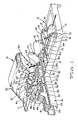
- Figure 1 is a perspective view embodying the preferred aspects of apparatus according to the present invention: and
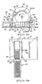
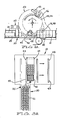
- Figures 2a/2b, 3a/3b and 4a/4b are respectively cross-sectional and plan views showing schematically the sequence of operations in the apparatus of Figure 1.
- Referring first to Figure 1 there is shown apparatus including a
feeding device 10 for supporting a stack of wrap aroundcarton blanks 50 on a conveying means 11: Thefeed device 10 includes a transfer mechanism (not shown) for moving each successive carton blank 50 in the direction of arrow A onto a carton conveyor mechanism shown generally at 12. The carton blank transfer mechanism may be of any suitable type known in this art. The construction of theconveyor mechanism 12 is also not essential, however, in one embodiment it may be formed by a pair ofendless chains carton engaging fingers 15 moving between substantially stationary carton slide supports 16. Thechains - Advantageously the carton blanks are folded to form a partly erected
carton 51 as they are transferred by the transfer mechanism onto theconveyor mechanism 12 at an initialproduct receiving position 17. At the initial product receiving position the partly erectedcartons 51 present aproduct receiving zone 53 to aproduct delivery station 22 as hereinafter described. Further folding means may be provided as the cartons move along theconveyor mechanism 12 to the finalproduct receiving position 18 and thereafter to subsequent operation steps shown schematically at 19 where a finished carton is shown folded about the packed products. The various carton folding mechanisms, glue applicators, and glue fixing mechanisms have not been shown for the sake of clarity and due to the fact that they would be well known to those skilled in this art and they do not form part of the present invention. - As shown in Figure 1 there is provided a product delivery means 20 for carrying a supply of
discrete products 21 to theproduct delivery station 22 generally adjacent to the initialproduct receiving position 17 of thecartons 51 on theconveyor mechanism 12. In the example illustrated the individual products are shown as soft drink cans or the like, however, it will be appreciated that the apparatus is adaptable for use with a variety of packaged products or other articles. The product delivery means 20 includes conveyor means 55 which has aslat conveyor 23 continuously moving and supporting theproducts 21 thereon. A plurality ofguideways 54 for theproducts 21 are provided to arrange the products in the number of rows needed to fill the width of the erected carton. Theguideways 54 are formed by upstanding dividing means such asplates 24 extending longitudinally along the conveyor means 20. In the embodiment illustrated, five such plates are provided dividing theproducts 21 into four streams. Agate mechanism 25 is provided to enable a predetermined quantity ofproducts 21 to pass to thedelivery station 22. Thegate mechanism 25 preferably comprises aslide block 26 with actuating means to move the block onshafts 27. The slide block carriespartitions 28 which are normally in line with theplates 24 forming the guideways of the conveyor means 20. However, the slide block is also capable of moving thepartitions 28 across the conveyor means to a position generally midway across the guideways to thereby block further movement of theproducts 21 towards thedelivery station 21. The products upstream of thegate mechanism 25 remain stationary while theconveyor 23 continues to slide beneath the products and to move the products that have passed thegate mechanism 25 to thedelivery station 22. As shown in Figures 2A, 3A and 4A there is provided apivotable stop member 29 at the end of theconveyor 23 which retains theproducts 21 at thedelivery station 22 until the actual loading in thecartons 10 commences. Once product loading commences as can be seen in Figure 3A, thestop member 29 pivots downwardly to allow theproducts 21 to move into the cartons. - Referring again to Figure 1 there is provided actuating means shown generally at 30 adjacent to the
product delivery station 22 for moving the products from the delivery station into thecartons 10 as they move continuously from theinitial receiving station 17 to thefinal receiving station 18. - The actuating means 30 comprises a pair of
endless chains sprocket wheels larger sprocket wheels sprocket wheels drive motor 38 provides the driving means for the shaft 37. The pair ofchains cartons 51 on theconveyor mechanism 12. Thechains slide bars 39 shown in Figure 1 and a second pair of slide bars (not shown) 180° out of phase with the slide bars shown. Theslide bars 39 are arranged generally parallel to the direction of movement of thecartons 51 on theconveyor mechanism 12. Each of the pairs of slide bars carries pusher member in the form of aslide block pusher finger chains slide bars 39. - As is illustrated in Figures 2A, 3A and 4A, the pusher fingers travel along an
endless path 56 comprising twocurved sections sections 57 and 59. Thecurved section 60 has a radius of curvature greater than thecurved section 58 and provides for the acceleration and deceleration of thepusher members - As shown in the drawings, the
conveyor mechanism 12 includes a plurality ofpusher bars 44 arranged between the carton receiving positions, thepusher bars 44 having aportion 45 extending towards thedelivery station 22 whereby theportion 45 is adapted to sweep theproducts 21 at the delivery station in the direction of movement of theconveyor mechanism 12. At the same time as one of thepusher fingers products 21 at the delivery station, one of thepusher bar portions 45 moves theproducts 21 downstream and at the same time engages thepusher fingers slide blocks slide bars 39. As a result of this inter-engagement of the pusher bars and the slide blocks, theslide blocks products 21 are finally loaded into the cartons at the position indicated at 18. - Referring to Figures 2A, 2B, 3A, 3B, 4A and 4B, the sequence of operation of the loading or packing steps will be described. Initially in Figures 2A and 2B, a predetermined quantity of products 21 (twenty-four in the embodiment illustrated) have been carried by the conveyor means 20 through the
gate mechanism 25 which has been operated by any suitable control means. The predetermined number ofproducts 21 are collected at thedelivery station 22 against the stop means 29. In this position, theproducts 21 await the downward passage of thepusher finger 42 and the sweeping movement of thepusher bar portion 45. Figures 3A and 3B show the position where theproducts 21 have been partially. loaded into thecarton 10. In this position theslide block 40 andpusher finger 42 have been engaged by thepusher bar portion 45 and are being moved therewith while also moving inwardly along theendless path 56 by way of their connection to thechains pusher finger 42 is accelerating and thereby accelerating the movement of theproducts 21 into thecarton 10. When thepusher finger 42 reaches the position shown in Figures 4A and 4B with the products loaded into thecarton 10, the finger is starting to decelerate and move upwardly to clear the products in thecarton 10. This arrangement of acceleration and deceleration of the pusher fingers is of some advantage in the loading procedure. As will be observed from Figures 4A and 4B, upon completion of the loading procedure into one carton, a further quantity ofproducts 21 are being transferred to thedelivery station 22 ready for engagement by thesecond slide block 41 and its associatedpusher finger 43. Furthermore it will be appreciated that upon the return movement of each of slide blocks 40, 41, cam means shown schematically at 46 is provided to move the slide blocks back to the initial upstream position. - It is anticipated that the arrangement disclosed herein will result in substantially doubling the through flow capability of the apparatus by utilising the transport time of the
cartons 10 on theconveyor mechanism 12 to load the cartons.
Claims (16)
1. Packing apparatus arranged to pack discrete products into containers, said apparatus comprising means for receiving containers and transporting said containers past a product delivery station, product delivery means arranged to deliver products to said delivery station, said packing apparatus being characterized by actuating means arranged adjacent said delivery station, said actuating means being capable of movement both in a direction towards the containers being transported past the delivery station and in the direction of movement of said containers whereby a predetermined number of said products are moved thereby into a said container while the container is transported past said delivery station.
2. Packing apparatus according to claim 1 characterized in that said containers are cartons and a feed device (10) is provided for supporting a plurality of carton blanks (50) and for sequentially supplying partly erected cartons (51) to carton conveying means (12) whereby each said partly erected carton blank (51) presents a product receiving zone (53) to said product delivery station (22) as the carton (51) is transported past the delivery station by the carton conveying means (12).
3. Packing apparatus according to claim 1 or claim 2 characterized in that said product delivery means includes product conveyor means (55) arranged to carry products to said delivery station (22).
4. Packing apparatus according to claim 3 characterized in that said product conveyor means (55) includes a plurality of guideways adapted to arrange said products in adjacent rows and a moving conveyor surface (23) arranged to carry said products along said guideways (54).
5. Packing apparatus according to claim 4 characterized in that said delivery station (22) includes gateway means (25) adapted to open or close said guideways (54), said gateway means (25) being closable after a predetermined number of products have passed therethrough.
6. Packing apparatus according to claim 5 characterized in that said guideways (54) are formed by substantially parallel stationary divider means (24) arranged above the moving conveyor surface (23), said stationary divider means (24) being spaced apart an amount sufficient to allow products to pass therebetween in single file, and said gateway means (25) including gate elements (28) arranged, in the open position of said gateway means (28), to form an extension of said divider means (24), and in the closed position of said gateway means (28), to form an obstruction in said guideways (54) to prevent continued movement of said products past said gateway means (25).
7. Packing apparatus according to claim 5 or claim 6 characterized in that the delivery station (22) includes retractable stop means (29) adapted to selectably prevent movement of said predetermined number of products on said moving conveyor surface (23) beyond a selected position.
8. Packing apparatus according to any one of claims 1 to 7 characterized in that said actuating means (30) comprises at least one pusher member (40,41) adapted to engage a predetermined number of said products at said delivery station (22) and push said products in a direction substantially transverse to the direction of movement of said containers (51).
9. Packing apparatus according to claim 8 characterized in that the or each said pusher member (40,41) is arranged to follow an endless path (56).
10. Packing apparatus according to claim 9 characterized in that the endless path (56) comprises a first curved section (60) and a second curved section (58), the first curved section (60) being of substantially greater diameter than said second curved section (58), said endless path (56) further including a third section (57) interconnecting the first curved section (60) with said second curved section (58) and being substantially parallel to the intended path of travel of the products from the delivery station (22) to the containers (51), and a fourth section (59) interconnecting the second curved section (58) with the first curved section (60).
11. Packing apparatus according to claim 9 or claim 10 characterized in that an endless flexible drive means (31,32) is provided arranged to pass over spaced wheel elements (33,34,35,36), and at least one slide bar means (39) mounted to said flexible drive means (31,32) extending in the direction of movement of said containers (51), said pusher member or members (40,41) being slidably mounted on a respective said slide bar means (39).
12. Packing apparatus according to claim 11 characterized in that an abutment means (45) movable with said containers (51) is arranged to operably engage a said pusher member (40,41) to move said pusher member (40,41) in the direction of movement of said containers (51) as the flexible drive means (31,32) moves said pusher member (40,41) transversely twoards said containers (51), said abutment means (45) simultaneously engaging said products at the delivery station (22).
13. A method of packing products into containers as said containers (51) are moved along a path of movement defined by container conveyor means (12), said products being delivered in predetermined numbers to a delivery station (22) adjacent to the path of movement (12) of said containers, said method being characterized in that a said predetermined number of said products are moved towards said path of movement (12) of said containers (51) while moving said predetermined number of said products in the direction of movement of said containers (51) whereby said products are delivered into a respective one of the containers (51) on said container conveyor means (12).
14. A method according to claim 13 characterized in that said containers are cartons and carton blanks (51) are maintained in a stack (10) and are delivered sequentially to said container conveyor means (12) while being folded to a partially erected state (51), said cartons in said partially erected state (51) defining a product receiving zone (55).
15. A method according to claim 14 characterized in that said partially erected cartons (51) are closed about said products after said products are delivered into said product receiving zone (53) and are fastened in said closed position.
16. A packed container produced according to the method of any one of claims 13 to 15.
Applications Claiming Priority (2)
| Application Number | Priority Date | Filing Date | Title |
|---|---|---|---|
| AU3684/82 | 1982-04-21 | ||
| AU368482 | 1982-04-21 |
Publications (2)
| Publication Number | Publication Date |
|---|---|
| EP0092402A2 true EP0092402A2 (en) | 1983-10-26 |
| EP0092402A3 EP0092402A3 (en) | 1984-06-20 |
Family
ID=3694152
Family Applications (1)
| Application Number | Title | Priority Date | Filing Date |
|---|---|---|---|
| EP83302147A Withdrawn EP0092402A3 (en) | 1982-04-21 | 1983-04-15 | Improved carton packing apparatus |
Country Status (3)
| Country | Link |
|---|---|
| EP (1) | EP0092402A3 (en) |
| JP (1) | JPS58193203A (en) |
| AU (1) | AU1381983A (en) |
Cited By (7)
| Publication number | Priority date | Publication date | Assignee | Title |
|---|---|---|---|---|
| EP0117974A1 (en) * | 1983-03-05 | 1984-09-12 | Kolbus GmbH & Co. KG | Process and device for manufacturing collective packages |
| WO2003064270A3 (en) * | 2002-01-28 | 2003-12-24 | Focke & Co | Method and device for producing boxed packaging for cigarettes |
| US7726097B2 (en) * | 2006-08-08 | 2010-06-01 | Multivac Sepp Haggenmuller Gmbh & Co. Kg | Packaging machine support device |
| WO2014190966A1 (en) * | 2013-05-31 | 2014-12-04 | Meurer Verpackungssysteme Gmbh | Packaging machine |
| ITBO20130388A1 (en) * | 2013-07-23 | 2015-01-24 | Gd Spa | UNIT AND METHOD OF WRAPPING FOR THE BENDING OF A BLOCKED IN A PACKING MACHINE. |
| DE102018112545A1 (en) * | 2018-05-25 | 2019-11-28 | Krones Aktiengesellschaft | Transport system and method for moving articles towards a packaging machine |
| CN114056655A (en) * | 2021-12-03 | 2022-02-18 | 广州叁立机械设备有限公司 | A lid packing device |
Family Cites Families (1)
| Publication number | Priority date | Publication date | Assignee | Title |
|---|---|---|---|---|
| US3269091A (en) * | 1962-09-19 | 1966-08-30 | Bartelt Engineering Co Inc | Cartoning machine |
-
1982
- 1982-04-21 AU AU13819/83A patent/AU1381983A/en not_active Abandoned
-
1983
- 1983-04-15 EP EP83302147A patent/EP0092402A3/en not_active Withdrawn
- 1983-04-19 JP JP6987783A patent/JPS58193203A/en active Pending
Cited By (10)
| Publication number | Priority date | Publication date | Assignee | Title |
|---|---|---|---|---|
| EP0117974A1 (en) * | 1983-03-05 | 1984-09-12 | Kolbus GmbH & Co. KG | Process and device for manufacturing collective packages |
| WO2003064270A3 (en) * | 2002-01-28 | 2003-12-24 | Focke & Co | Method and device for producing boxed packaging for cigarettes |
| US7726097B2 (en) * | 2006-08-08 | 2010-06-01 | Multivac Sepp Haggenmuller Gmbh & Co. Kg | Packaging machine support device |
| WO2014190966A1 (en) * | 2013-05-31 | 2014-12-04 | Meurer Verpackungssysteme Gmbh | Packaging machine |
| US10501215B2 (en) | 2013-05-31 | 2019-12-10 | Illinois Tool Works Inc. | Packaging machine |
| ITBO20130388A1 (en) * | 2013-07-23 | 2015-01-24 | Gd Spa | UNIT AND METHOD OF WRAPPING FOR THE BENDING OF A BLOCKED IN A PACKING MACHINE. |
| EP2829481A1 (en) * | 2013-07-23 | 2015-01-28 | G.D Societa' Per Azioni | Packing method and unit for feeding a blank on a packing machine |
| US9821526B2 (en) | 2013-07-23 | 2017-11-21 | G. D. Societa' Per Azioni | Packing method and unit for folding a blank on a packing machine |
| DE102018112545A1 (en) * | 2018-05-25 | 2019-11-28 | Krones Aktiengesellschaft | Transport system and method for moving articles towards a packaging machine |
| CN114056655A (en) * | 2021-12-03 | 2022-02-18 | 广州叁立机械设备有限公司 | A lid packing device |
Also Published As
| Publication number | Publication date |
|---|---|
| AU1381983A (en) | 1983-10-27 |
| EP0092402A3 (en) | 1984-06-20 |
| JPS58193203A (en) | 1983-11-10 |
Similar Documents
| Publication | Publication Date | Title |
|---|---|---|
| US12060181B2 (en) | Continuous motion packaging machine with carton turning station | |
| US5148654A (en) | Packaging system | |
| US4642967A (en) | Packaging machine | |
| EP2027021B1 (en) | Continuous motion packaging method and system | |
| US7104027B2 (en) | Product packaging system | |
| US5456058A (en) | Stacked article cartoning apparatus | |
| US4571923A (en) | Packaging machine and method | |
| EP1278691B1 (en) | Apparatus and a method for collating and cartonning product units | |
| US3956868A (en) | Carton opening, filling and closing apparatus | |
| US4443995A (en) | Metering device and method | |
| CZ279197A3 (en) | Packaging machine for multiple packaging | |
| US3225510A (en) | Article cartoning machine | |
| US20030000182A1 (en) | Packaging machine and apparatus for wraparound cartons | |
| CN114206730A (en) | Folding upper fixed wings | |
| EP0092402A2 (en) | Improved carton packing apparatus | |
| CA1141646A (en) | Packaging machine | |
| AU2019249386B2 (en) | Packaging machine | |
| US4235329A (en) | Article grouping and tiering apparatus | |
| EP0337997B1 (en) | Carton packaging machine | |
| MXPA00002731A (en) | Article grouping mechanism |
Legal Events
| Date | Code | Title | Description |
|---|---|---|---|
| PUAI | Public reference made under article 153(3) epc to a published international application that has entered the european phase |
Free format text: ORIGINAL CODE: 0009012 |
|
| AK | Designated contracting states |
Designated state(s): BE CH DE FR GB IT LI LU NL SE |
|
| PUAL | Search report despatched |
Free format text: ORIGINAL CODE: 0009013 |
|
| AK | Designated contracting states |
Designated state(s): BE CH DE FR GB IT LI LU NL SE |
|
| STAA | Information on the status of an ep patent application or granted ep patent |
Free format text: STATUS: THE APPLICATION IS DEEMED TO BE WITHDRAWN |
|
| 18D | Application deemed to be withdrawn |
Effective date: 19850221 |