EP0694436B1 - Vorrichtung zum Schnellverbinden eines Kindersitzes mit einem Kraftwagensitz - Google Patents
Vorrichtung zum Schnellverbinden eines Kindersitzes mit einem Kraftwagensitz Download PDFInfo
- Publication number
- EP0694436B1 EP0694436B1 EP95830310A EP95830310A EP0694436B1 EP 0694436 B1 EP0694436 B1 EP 0694436B1 EP 95830310 A EP95830310 A EP 95830310A EP 95830310 A EP95830310 A EP 95830310A EP 0694436 B1 EP0694436 B1 EP 0694436B1
- Authority
- EP
- European Patent Office
- Prior art keywords
- backrest
- motor
- seat
- child seat
- vehicle seat
- Prior art date
- Legal status (The legal status is an assumption and is not a legal conclusion. Google has not performed a legal analysis and makes no representation as to the accuracy of the status listed.)
- Revoked
Links
- 238000010168 coupling process Methods 0.000 title claims description 18
- 238000005859 coupling reaction Methods 0.000 title claims description 18
- 230000008878 coupling Effects 0.000 title claims description 16
- 239000002184 metal Substances 0.000 description 2
- 238000010276 construction Methods 0.000 description 1
- 238000007796 conventional method Methods 0.000 description 1
Images


Classifications
-
- B—PERFORMING OPERATIONS; TRANSPORTING
- B60—VEHICLES IN GENERAL
- B60N—SEATS SPECIALLY ADAPTED FOR VEHICLES; VEHICLE PASSENGER ACCOMMODATION NOT OTHERWISE PROVIDED FOR
- B60N2/00—Seats specially adapted for vehicles; Arrangement or mounting of seats in vehicles
- B60N2/24—Seats specially adapted for vehicles; Arrangement or mounting of seats in vehicles for particular purposes or particular vehicles
- B60N2/26—Seats specially adapted for vehicles; Arrangement or mounting of seats in vehicles for particular purposes or particular vehicles for children
- B60N2/28—Seats readily mountable on, and dismountable from, existing seats or other parts of the vehicle
- B60N2/2821—Seats readily mountable on, and dismountable from, existing seats or other parts of the vehicle having a seat and a base part
-
- B—PERFORMING OPERATIONS; TRANSPORTING
- B60—VEHICLES IN GENERAL
- B60N—SEATS SPECIALLY ADAPTED FOR VEHICLES; VEHICLE PASSENGER ACCOMMODATION NOT OTHERWISE PROVIDED FOR
- B60N2/00—Seats specially adapted for vehicles; Arrangement or mounting of seats in vehicles
- B60N2/24—Seats specially adapted for vehicles; Arrangement or mounting of seats in vehicles for particular purposes or particular vehicles
- B60N2/26—Seats specially adapted for vehicles; Arrangement or mounting of seats in vehicles for particular purposes or particular vehicles for children
- B60N2/28—Seats readily mountable on, and dismountable from, existing seats or other parts of the vehicle
- B60N2/2857—Seats readily mountable on, and dismountable from, existing seats or other parts of the vehicle characterised by the peculiar orientation of the child
- B60N2/286—Seats readily mountable on, and dismountable from, existing seats or other parts of the vehicle characterised by the peculiar orientation of the child forward facing
-
- B—PERFORMING OPERATIONS; TRANSPORTING
- B60—VEHICLES IN GENERAL
- B60N—SEATS SPECIALLY ADAPTED FOR VEHICLES; VEHICLE PASSENGER ACCOMMODATION NOT OTHERWISE PROVIDED FOR
- B60N2/00—Seats specially adapted for vehicles; Arrangement or mounting of seats in vehicles
- B60N2/24—Seats specially adapted for vehicles; Arrangement or mounting of seats in vehicles for particular purposes or particular vehicles
- B60N2/26—Seats specially adapted for vehicles; Arrangement or mounting of seats in vehicles for particular purposes or particular vehicles for children
- B60N2/28—Seats readily mountable on, and dismountable from, existing seats or other parts of the vehicle
- B60N2/2887—Fixation to a transversal anchorage bar, e.g. isofix
- B60N2/2893—Fixation to a transversal anchorage bar, e.g. isofix coupled to the seat sub-frame
Definitions
- the present invention relates to a device for quick coupling of a child seat to a motor-vehicle seat (see, for example, GB-A-2 116 837, corresponding to the preamble of claim 1.)
- the object of the present invention is that of overcoming said drawbacks, by providing a device which enables a child seat to be connected rapidly directly to a motor-vehicle seat, with a simple, reliable and unexpensive structure.
- the invention provides a connecting device of the type described above and having the characterising features set forth in claim 1.
- each engagement element is comprised of a bolt projecting rearwardly from the backrest of the child seat and said receiver element is comprised of a bush mounted within a hole formed through the backrest of the motor-vehicle seat;
- the locking means are comprised of a latch slidable within said backrest frame in a direction transverse to the axis of the bolt, said latch being biassed by spring means towards a position locking said bolt and being manually moveable, against the action of the spring means, towards a position for release of the bolt.
- each engagement element is comprised of a bolt projecting forwardly from the backrest of the motor-vehicle seat, and said receiver element is comprised of a hole formed through the backrest of the child seat; said locking means is comprised of a latch which is slidable within the backrest of the child seat in a direction transverse to the axis of said hole and is biassed by spring means towards a position for locking said bolt and is manually moveable, against the action of the spring means, towards a position for release of this bolt.
- each bolt has an articulated end portion, which is moveable to a position rotated by 90° with respect to the axis of the bolt for being received within a cooperating seat formed in the front face of the backrest of the motor-vehicle seat, when the child seat is not connected to this backrest.
- the connecting bolts do not project from the backrest and do not cause therefore any disturb to the passengers.
- each quick coupling is a coupling of the type known per se used for safety belts, wherein the engagement element is a tab and the receiver element is a buckle for safety belts.
- the buckle projects rearwardly from the child seat and the tab is fixed to the backrest frame of the motor-vehicle seat and projects forwardly from a hole formed through the backrest.
- the buckle is arranged at the rear of the child-seat with its receiving aperture facing downwardly, and the tab is fixed to the backrest frame of the motor-vehicle seat and projects forwardly from the gap between the cushion and the backrest of the motor-vehicle seat and has an end portion directed upwardly.
- the invention enables an easy and quick connection of the child seat, while providing a connection directly to the structure of the motor-vehicle seat, with resulting advantages also from the standpoint of safety.
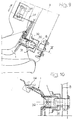
- numeral 1 generally designates a child seat comprising a backrest 2 from which there project rearwardly two cylindrical bolts 3, each of which is for cooperation with a receiver element 4, which will be described more in detail in the following, with which it constitutes a quick coupling.
- numeral 5 generally designates a motor-vehicle seat, for example a rear seat, comprising a cushion 6 and a backrest 7 provided with a metal frame 8.
- Each cylindrical bolt has one end 9 rigidly connected to the structure of the child seat 1, and is adapted to be received in a bush 10, forming part of said receiver element 4, which is inserted in a hole 11 formed through the backrest 7.
- Each bolt 3 has, adjacent to its end nose 3a, a narrowed neck 3b with engages the narrow portion of an aperture 12 having the shape of a keyhole formed in a plate latch 13.
- Latch 13 is slidably mounted between two plates 14, 15 fixed to frame 8 of the backrest of the seat of the motor-vehicle by screws 16.
- each locking bolt 3 is fixed to the backrest of the motor-vehicle seat, whereas the corresponding receiver element 4 is provided on the child seat 1.
- the structure of the backrest of the child seat 1 there are slidably mounted two latch plates 13 which project on both sides of seat 1 with ends provided with push bottoms 18.
- each plate 13 has an aperture 12 shaped as a keyhole with a narrow portion which is able to engage a narrow neck 3b preventing withdrawal of the end nose 3a.
- each bolt 3 is welded to a plate 19 fixed by screws 16 to frame 8 of the backrest 7 of the motor-vehicle seat 5.
- each bolt 3 projects forwardly from backrest 7 and engages a hole 20 formed in the backrest of the child seat 1.
- bolts 3 would project from the front surface of backrest 7 disturbing thereby the occupants.
- each bolt 3 is articulated around an intermediate axis 21, so that an end portion 22 thereof may be rotated by 90° with respect to the axis of bolt 3 (to the position indicated by dotted line in figures 6 and 8) where it is arranged inside a seat 23 formed in the front surface of the backrest 7 and is held by a fork element 24.
- each quick coupling is of the type known per se normally used for safety belts. More precisely, each quick coupling has a tab 30 which is welded to frame 7 of the backrest of the motor-vehicle seat and projects in a seat 31 formed forwardly thereto said tab being adapted to be snap received into a receiver element 32 of the type of a buckle of a safety belt which is fixed at the rear of the child seat 1.
- receiver element 32 The inside structure of receiver element 32 is not illustrated herein in detail, since, as already indicated, it may be of the known type conventionally used for safety belts.
- This buckle may be, according to the conventional technique adopted in this field, provided with a device for releasing tab 30, which in this case can be operated remotely by a cable 33 ending with a driving lever 34 arranged on one side of the child seat 1.
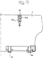
- FIGS 11-13 show a variant in which buckle 32 is also arranged at the rear of the child seat 1, but with its receiving aperture facing downwardly, whereas tab 30 is fixed to frame 7 by bolts 33 and projects through the space between cushion 6 and backrest 7, with an end portion 30 directed upwardly.
- a further quick coupling unit between the top of backrest 2 of the child seat 1 and the backrest 7 of the motor-vehicle seat 5.
- This unit comprises a pair (as in the case of the illustrated example) or also two pairs of quick coupling members, one constituted by a receiver element 32a of the type of a buckle for safety belts, carried by the back of backrest 7 of seat 5 adjacent to its stop, and the other being constituted by a tab 30a which can be snap engaged within a buckle 32a and anchored to the end of a belt 34.
- This belt 34 of the type conventionally used for safety belts, is fixed at its other end to the top of backrest 2 of the child seat 1.
- belt 34 In the condition of engagement between tab 30a and buckle 32a, belt 34 is normally under tension.
- FIGS 16-19 show another embodiment in which two engagement members 50 in form of U-shaped brackets are fixed to a cross-member 51 of sheet-metal forming part of the frame 8 of the backrest by nuts 52 screwed onto threaded end portions 53 of brackets 50.
- Brackets 50 project forwardly through apertures provided in the backrest padding and are covered by plastic caps 54 with apertures 55 to allow receiver elements of any type provided on the child seat to reach the engagement elements 50.
- the receiver elements for example may have the structure of a latch mechanism of the conventional type used in motor-vehicle doors.
- Cross-member 8 on its turn is fixed by bolts 56a to U-shaped brackets 56 which are pivotally mounted within brackets 57 fixed to the motor-vehicle body, to allow tilting of the rear seat backrest.
- Figures 20-22 show a variant of the embodiment of figures 16-19, which can be used in case the device according to the invention has to be adapted on a motor-vehicle originally produced without such a device.
Claims (8)
- Vorrichtung zur Befestigung eines Kindersitzes (1) an einem Sitz (5) eines Kraftfahrzeuges, mit zumindest zwei Kupplungen zur Verbindung des Kindersitzes mit dem Rahmen des Sitzes des Kraftfahrzeuges, dadurch gekennzeichnet, daß die Kupplungen in Form von Schnellkupplungen ausgeführt sind, von denen jede umfaßt:ein Aufnahmebauteil (4) und ein Bauteil (3), welches mit dem Aufnahmebauteil (4) in Eingriff gelangt, wobei diese beiden Bauteile (3, 4) am Kindersitz (1) und an dem Rahmen (8) der Rückenlehne (7) des Sitzes (5) des Kraftfahrzeuges angeordnet sind, so daß eines der Bauteile (3, 4) am Kindersitz (1) und das andere Bauteil (3, 4) am Sitz (5) angeordnet ist; undeine freigebbare Verriegelungseinrichtung (13, 32), die eine erste Position aufweist, um jedes der Eingriffbauteile (3) innerhalb des zugeordneten Aufnahmebauteils (4) zu verriegeln und die eine zweite Position aufweist, um das Eingriffsbauteil (3) von dem Aufnahmebauteil (4) freizugeben.
- Vorrichtung nach Anspruch 1, dadurch gekennzeichnet, daß jedes Eingriffsbauteil (3) einen Bolzen aufweist, der von der Rückenlehne des Kindersitzes (1) nach hinten vorsteht, wobei das Aufnahmebauteil (4) eine Hülse (10) aufweist, die in einer Öffnung (11) aufgenommen ist, die in der Rückenlehne (7) des Sitzes (5) des Kraftfahrzeuges ausgebildet ist, wobei die Verriegelungseinrichtung einen Riegel (13) aufweist, der innerhalb des Rahmens (8) der Rückenlehne (7) in einer Richtung quer zu der Achse des Bolzens (3) verschiebbar angeordnet ist, wobei der Riegel (13) durch eine Feder (17) unter Vorspannung gehalten ist, und zwar in Richtung einer Position zur Verriegelung des Bolzens (3), sowie der Riegel (13) manuell verschiebbar ist, nämlich gegen die Wirkung der Feder (17), und zwar in eine Richtung zu einer Position, in der der Bolzen (3) freigegeben ist.
- Vorrichtung nach Anspruch 1, dadurch gekennzeichnet, daß jedes Eingriffsbauteil (3) einen Bolzen aufweist, der von der Rückenlehne (7) des Sitzes (5) des Kraftfahrzeuges nach vorne vorsteht, wobei das Aufnahmebauteil (4) eine Öffnung (20) aufweist, die in der Rückenlehne des Kindersitzes (1) ausgebildet ist; die Verriegelungseinrichtung weist einen Riegel (13) auf, der innerhalb der Rückenlehne des Kindersitzes (1) in einer Richtung quer zu der Achse der Öffnung (20) verschiebbar angeordnet ist, wobei der Riegel (13) durch eine Feder (17) unter Vorspannung gehalten ist, und zwar in Richtung einer Position zur Verriegelung des Bolzens (3), sowie der Riegel (13) manuell verschiebbar ist, nämlich gegen die Wirkung der Feder (17), und zwar in eine Richtung zu einer Position, in der der Bolzen (3) freigegeben ist, wobei der Bolzen (3) einen gelenkig verbundenen Endabschnitt (22) aufweist, der in eine Position verlagerbar ist, die relativ zu der Achse des Bolzens (3) um 90° verdreht ist, um innerhalb einer zugehörigen Aufnahme (23) aufgenommen zu sein, die in der Vorderfläche der Rückenlehne (7) des Sitzes (5) des Kraftfahrzeuges ausgebildet ist, wenn der Kindersitz (1) nicht an der Rückenlehne (7) befestigt ist.
- Vorrichtung nach Anspruch 1, dadurch gekennzeichnet, daß jede Schnellkupplung eine Kupplung ist, die an sich als Kupplungstyp für Sicherheitsgurte bekannt ist, und bei der das Eingriffsbauteil ein flacher Stecker (30) ist sowie das Aufnahmebauteil eine Schnalle (32) für Sicherheitsgurte ist.
- Vorrichtung nach Anspruch 4, dadurch gekennzeichnet, daß die Schnalle (32) von dem Kindersitz (1) nach hinten vorsteht und daß der Stecker (30) an dem Rahmen (8) der Rückenlehne (7) des Sitzes des Kraftfahrzeuges fixiert ist und nach vorne vorsteht, durch eine Öffnung, die in der Rückenlehne (7) ausgebildet ist.
- Vorrichtung nach Anspruch 4, dadurch gekennzeichnet, daß die Schnalle (32) an der Rückseite des Kindersitzes (1) angeordnet ist, wobei deren Aufnahmeöffnung nach unten zeigt, sowie der Stecker (30) an dem Rahmen (8) der Rückenlehne (7) des Sitzes (5) des Kraftfahrzeuges fixiert ist und nach vorne vorsteht, nämlich durch einen Spalt zwischen dem Sitz (6) und der Rückenlehne (7) des Sitzes (5) des Kraftfahrzeuges, wobei der Stecker (30) einen Endabschnitt (30a) aufweist, der nach oben gerichtet ist.
- Vorrichtung nach Anspruch 4, dadurch gekennzeichnet, daß die Schnalle (32a) an der Rückseite der Rückenlehne (7) des Sitzes (5) des Kraftfahrzeuges angeordnet ist, und zwar benachbart dem oberen Ende davon, wobei der Stecker (30a) mit einem Gurt (34) verbunden ist, der vom Typ Sicherheitsgurt ist, und der an dem oberen Abschnitt der Rückenlehne (2) des Kindersitzes (1) verankert ist.
- Vorrichtung nach Anspruch 1, dadurch gekennzeichnet, daß das Eingriffsbauteil ein U-förmiger Träger (50) ist, der an einem Querträger (58) fixiert ist, der einen Teil des Rahmens (8) der Rückenlehne (7) des Sitzes (5) bildet.
Applications Claiming Priority (2)
| Application Number | Priority Date | Filing Date | Title |
|---|---|---|---|
| ITTO940617 | 1994-07-26 | ||
| IT94TO000617A IT1266039B1 (it) | 1994-07-26 | 1994-07-26 | Dispositivo per il collegamento rapido di un sedile per bambino ad un sedile di autoveicolo. |
Publications (2)
| Publication Number | Publication Date |
|---|---|
| EP0694436A1 EP0694436A1 (de) | 1996-01-31 |
| EP0694436B1 true EP0694436B1 (de) | 1998-04-22 |
Family
ID=11412701
Family Applications (1)
| Application Number | Title | Priority Date | Filing Date |
|---|---|---|---|
| EP95830310A Revoked EP0694436B1 (de) | 1994-07-26 | 1995-07-18 | Vorrichtung zum Schnellverbinden eines Kindersitzes mit einem Kraftwagensitz |
Country Status (3)
| Country | Link |
|---|---|
| EP (1) | EP0694436B1 (de) |
| DE (1) | DE69502142T2 (de) |
| IT (1) | IT1266039B1 (de) |
Cited By (6)
| Publication number | Priority date | Publication date | Assignee | Title |
|---|---|---|---|---|
| GB2302274B (en) * | 1995-06-16 | 1997-06-04 | Daimler Benz Ag | Device for the fastening of a child's seat |
| GB2322542A (en) * | 1997-02-26 | 1998-09-02 | Johnson Controls Automotive Uk | Mounting of vehicle child restraint |
| US5918934A (en) * | 1998-11-09 | 1999-07-06 | Johnson Controls Technology Company | Child seat attachment system |
| EP0993984A2 (de) | 1998-10-17 | 2000-04-19 | Dr.Ing. h.c.F. Porsche Aktiengesellschaft | Haltevorrichtung zur lösbaren Befestigung eines Kindersitzes an einem Fahrzeugsitz |
| US6361115B1 (en) | 1999-02-03 | 2002-03-26 | Bertrand Faure Equipements Sa | Vehicle seat with anchoring wire to secure an element onto this seat |
| US6582016B1 (en) | 2001-07-31 | 2003-06-24 | Johnson Controls Technology Company | Seat trim closeout for isofix systems |
Families Citing this family (11)
| Publication number | Priority date | Publication date | Assignee | Title |
|---|---|---|---|---|
| US6601917B1 (en) * | 1999-03-03 | 2003-08-05 | Intier Automotive Inc. | Cover for child seat anchor |
| NL1015020C2 (nl) * | 2000-04-26 | 2001-10-30 | Maxi Miliaan Bv | Bevestigingselement voor het losneembaar bevestigen van een stoeldrager aan een voertuigstoel alsmede dergelijke stoeldragers. |
| FR2822766B1 (fr) * | 2001-03-27 | 2003-06-13 | Faurecia Sieges Automobile | Siege de vehicule automobile dote d'un dispositif d'ancrage d'elements tels que des sieges pour enfant |
| CA2372829A1 (en) * | 2002-02-19 | 2003-08-19 | Summo Steel Corporation | Weldless child safety restraint system for an automobile |
| US7131693B2 (en) * | 2003-05-16 | 2006-11-07 | M & C Corporation | Restraint anchorage for a child restraint system |
| US6983526B2 (en) | 2003-06-24 | 2006-01-10 | M & C Corporation | Cold formed latch wire |
| DE102004049321B4 (de) * | 2004-10-09 | 2014-01-23 | Volkswagen Ag | Befestigungsvorrichtung für einen Kindersitz in einem Kraftfahrzeug |
| US9022340B2 (en) | 2011-03-21 | 2015-05-05 | Techform Products Limited | Formed tube with formed wire rivet |
| DE102014221886B4 (de) | 2014-10-28 | 2022-01-05 | Bayerische Motoren Werke Aktiengesellschaft | Kraftfahrzeug |
| JP6582574B2 (ja) * | 2015-06-11 | 2019-10-02 | トヨタ紡織株式会社 | 乗物用シート |
| CN109017472B (zh) * | 2018-08-09 | 2020-12-01 | 广汽本田汽车有限公司 | 一种用于新能源汽车的便于安放儿童座椅的座椅 |
Family Cites Families (4)
| Publication number | Priority date | Publication date | Assignee | Title |
|---|---|---|---|---|
| DE4125959C1 (de) * | 1991-08-06 | 1992-10-15 | Deutsche Airbus Gmbh, 2000 Hamburg, De | |
| FR2680734B1 (fr) | 1991-09-04 | 1997-03-14 | Baby Relax Snc | Siege automobile pour enfant. |
| DE4204224C1 (en) * | 1992-02-13 | 1993-07-29 | Curt Wuerstl Vermoegensverwaltungs Gmbh & Co. Kg, 8670 Hof, De | Inflatable child seat of plastics material, layered fabric or rubber with air compartments - forming shape and stability of child seat consisting of sitting and back parts with side walls for fixing to motor vehicle seat and inflated by compressed air line |
| DE9208438U1 (de) | 1992-06-24 | 1992-09-10 | Curt Wuerstl Vermoegensverwaltungs Gmbh & Co. Kg, 8670 Hof, De |
-
1994
- 1994-07-26 IT IT94TO000617A patent/IT1266039B1/it active IP Right Grant
-
1995
- 1995-07-18 EP EP95830310A patent/EP0694436B1/de not_active Revoked
- 1995-07-18 DE DE69502142T patent/DE69502142T2/de not_active Revoked
Cited By (10)
| Publication number | Priority date | Publication date | Assignee | Title |
|---|---|---|---|---|
| GB2302274B (en) * | 1995-06-16 | 1997-06-04 | Daimler Benz Ag | Device for the fastening of a child's seat |
| US5669663A (en) * | 1995-06-16 | 1997-09-23 | Mercedes-Benz Ag | Quick-action fastening device for a child's seat in a vehicle |
| GB2322542A (en) * | 1997-02-26 | 1998-09-02 | Johnson Controls Automotive Uk | Mounting of vehicle child restraint |
| US6354648B1 (en) | 1997-02-26 | 2002-03-12 | Johnson Controls Technology Company | Mounting for child-restraint system in vehicle |
| EP0993984A2 (de) | 1998-10-17 | 2000-04-19 | Dr.Ing. h.c.F. Porsche Aktiengesellschaft | Haltevorrichtung zur lösbaren Befestigung eines Kindersitzes an einem Fahrzeugsitz |
| US6334649B1 (en) | 1998-10-17 | 2002-01-01 | Dr. Ing. H.C.F. Porsche Aktiengesellschaft | Holding device for releasable fastening of a child seat to a vehicle seat |
| DE19847956B4 (de) * | 1998-10-17 | 2006-05-24 | Dr.Ing.H.C. F. Porsche Ag | Haltevorrichtung zur lösbaren Befestigung eines Kindersitzes an einem Fahrzeugsitz |
| US5918934A (en) * | 1998-11-09 | 1999-07-06 | Johnson Controls Technology Company | Child seat attachment system |
| US6361115B1 (en) | 1999-02-03 | 2002-03-26 | Bertrand Faure Equipements Sa | Vehicle seat with anchoring wire to secure an element onto this seat |
| US6582016B1 (en) | 2001-07-31 | 2003-06-24 | Johnson Controls Technology Company | Seat trim closeout for isofix systems |
Also Published As
| Publication number | Publication date |
|---|---|
| ITTO940617A1 (it) | 1996-01-26 |
| DE69502142T2 (de) | 1998-08-13 |
| ITTO940617A0 (it) | 1994-07-26 |
| DE69502142D1 (de) | 1998-05-28 |
| EP0694436A1 (de) | 1996-01-31 |
| IT1266039B1 (it) | 1996-12-16 |
Similar Documents
| Publication | Publication Date | Title |
|---|---|---|
| EP0694436B1 (de) | Vorrichtung zum Schnellverbinden eines Kindersitzes mit einem Kraftwagensitz | |
| US5121964A (en) | Motor-vehicle seat sitting unit equipped with a raisable central part for receiving a child's seat | |
| US5466044A (en) | Child safety seat | |
| US6276754B1 (en) | Child seat attachment assembly | |
| US5741046A (en) | Motor vehicle rear seat with a divided back rest | |
| US7896434B2 (en) | Seat assembly for a vehicle | |
| EP0944490B1 (de) | Sitzgleitschiene mit ständigem Engriff und Positionsspeicherungsmechanismus zum erleichterten Zugang | |
| EP0966364B1 (de) | Veränderbare rücksitzanordnung für kraftfahrzeuge | |
| US4770459A (en) | Lock assembly for pivotal vehicle seat | |
| CA1177032A (en) | Seat belt arrangement for the rear seats of motor vehicles | |
| EP0619201A1 (de) | Kindersicherheitssitze für Kraftfahrzeuge | |
| EP0471573A1 (de) | Fahrzeugsitzanordnung | |
| GB2329114A (en) | Child seat anchorage | |
| US8123293B2 (en) | Seat assembly with rotatable seat bottom | |
| EP0810933A1 (de) | Kraftfahrzeugrücksitz | |
| US4685716A (en) | Seat mounting arrangement | |
| US5106121A (en) | Occupant restraint belt anchorage arrangement | |
| US20040227384A1 (en) | Restraint anchorage for a child restraint system | |
| US4964608A (en) | Vehicle seat adjuster with integral positive locking traveling seat belt anchorage | |
| JPS62210143A (ja) | 自動車用シ−トのスライドレ−ル構造 | |
| EP0694437B1 (de) | Vorrichtung zum Schnellverbinden eines Kindersitzes mit einem Kraftwagensitz | |
| CA2688683A1 (en) | Seat assembly for a vehicle | |
| EP0748716B1 (de) | Gelenkbeschlag für einen Fahrzeugrücksitz | |
| AU687242B2 (en) | Integrated child seat with safety locking mechanism | |
| EP1268235B1 (de) | Mehrfach positionierbare und umkehrbare sitzeinrichtung |
Legal Events
| Date | Code | Title | Description |
|---|---|---|---|
| PUAI | Public reference made under article 153(3) epc to a published international application that has entered the european phase |
Free format text: ORIGINAL CODE: 0009012 |
|
| AK | Designated contracting states |
Kind code of ref document: A1 Designated state(s): DE FR GB IT SE |
|
| 17P | Request for examination filed |
Effective date: 19960411 |
|
| 17Q | First examination report despatched |
Effective date: 19970114 |
|
| GRAG | Despatch of communication of intention to grant |
Free format text: ORIGINAL CODE: EPIDOS AGRA |
|
| GRAG | Despatch of communication of intention to grant |
Free format text: ORIGINAL CODE: EPIDOS AGRA |
|
| GRAH | Despatch of communication of intention to grant a patent |
Free format text: ORIGINAL CODE: EPIDOS IGRA |
|
| RAP1 | Party data changed (applicant data changed or rights of an application transferred) |
Owner name: LEAR CORPORATION ITALIA S.P.A. |
|
| GRAH | Despatch of communication of intention to grant a patent |
Free format text: ORIGINAL CODE: EPIDOS IGRA |
|
| GRAA | (expected) grant |
Free format text: ORIGINAL CODE: 0009210 |
|
| AK | Designated contracting states |
Kind code of ref document: B1 Designated state(s): DE FR GB IT SE |
|
| ITF | It: translation for a ep patent filed |
Owner name: BUZZI, NOTARO&ANTONIELLI D'OULX |
|
| REF | Corresponds to: |
Ref document number: 69502142 Country of ref document: DE Date of ref document: 19980528 |
|
| ET | Fr: translation filed | ||
| PLBQ | Unpublished change to opponent data |
Free format text: ORIGINAL CODE: EPIDOS OPPO |
|
| PLBI | Opposition filed |
Free format text: ORIGINAL CODE: 0009260 |
|
| PLBQ | Unpublished change to opponent data |
Free format text: ORIGINAL CODE: EPIDOS OPPO |
|
| PLBI | Opposition filed |
Free format text: ORIGINAL CODE: 0009260 |
|
| PLBF | Reply of patent proprietor to notice(s) of opposition |
Free format text: ORIGINAL CODE: EPIDOS OBSO |
|
| 26 | Opposition filed |
Opponent name: AKTIEBOLAGET VOLVO Effective date: 19990119 Opponent name: JOHNSON CONTROLS GMBH Effective date: 19990118 |
|
| 26 | Opposition filed |
Opponent name: KEIPER GMBH & CO. Effective date: 19990119 Opponent name: AKTIEBOLAGET VOLVO Effective date: 19990119 Opponent name: JOHNSON CONTROLS GMBH Effective date: 19990118 |
|
| PGFP | Annual fee paid to national office [announced via postgrant information from national office to epo] |
Ref country code: FR Payment date: 19990630 Year of fee payment: 5 |
|
| PGFP | Annual fee paid to national office [announced via postgrant information from national office to epo] |
Ref country code: SE Payment date: 19990701 Year of fee payment: 5 |
|
| PLBF | Reply of patent proprietor to notice(s) of opposition |
Free format text: ORIGINAL CODE: EPIDOS OBSO |
|
| PLBF | Reply of patent proprietor to notice(s) of opposition |
Free format text: ORIGINAL CODE: EPIDOS OBSO |
|
| PG25 | Lapsed in a contracting state [announced via postgrant information from national office to epo] |
Ref country code: SE Free format text: LAPSE BECAUSE OF NON-PAYMENT OF DUE FEES Effective date: 20000719 |
|
| EUG | Se: european patent has lapsed |
Ref document number: 95830310.9 |
|
| PG25 | Lapsed in a contracting state [announced via postgrant information from national office to epo] |
Ref country code: FR Free format text: LAPSE BECAUSE OF NON-PAYMENT OF DUE FEES Effective date: 20010330 |
|
| PLAW | Interlocutory decision in opposition |
Free format text: ORIGINAL CODE: EPIDOS IDOP |
|
| REG | Reference to a national code |
Ref country code: FR Ref legal event code: ST |
|
| APAC | Appeal dossier modified |
Free format text: ORIGINAL CODE: EPIDOS NOAPO |
|
| APAE | Appeal reference modified |
Free format text: ORIGINAL CODE: EPIDOS REFNO |
|
| APAC | Appeal dossier modified |
Free format text: ORIGINAL CODE: EPIDOS NOAPO |
|
| REG | Reference to a national code |
Ref country code: GB Ref legal event code: IF02 |
|
| APCC | Communication from the board of appeal sent |
Free format text: ORIGINAL CODE: EPIDOS OBAPO |
|
| PLBQ | Unpublished change to opponent data |
Free format text: ORIGINAL CODE: EPIDOS OPPO |
|
| PLAB | Opposition data, opponent's data or that of the opponent's representative modified |
Free format text: ORIGINAL CODE: 0009299OPPO |
|
| PGFP | Annual fee paid to national office [announced via postgrant information from national office to epo] |
Ref country code: GB Payment date: 20030709 Year of fee payment: 9 |
|
| PGFP | Annual fee paid to national office [announced via postgrant information from national office to epo] |
Ref country code: DE Payment date: 20030731 Year of fee payment: 9 |
|
| R26 | Opposition filed (corrected) |
Opponent name: KEIPER GMBH & CO. Effective date: 19990119 Opponent name: AKTIEBOLAGET VOLVO Effective date: 19990119 Opponent name: JOHNSON CONTROLS GMBH Effective date: 19990118 |
|
| APBU | Appeal procedure closed |
Free format text: ORIGINAL CODE: EPIDOSNNOA9O |
|
| RDAF | Communication despatched that patent is revoked |
Free format text: ORIGINAL CODE: EPIDOSNREV1 |
|
| RDAG | Patent revoked |
Free format text: ORIGINAL CODE: 0009271 |
|
| STAA | Information on the status of an ep patent application or granted ep patent |
Free format text: STATUS: PATENT REVOKED |
|
| 27W | Patent revoked |
Effective date: 20040118 |
|
| GBPR | Gb: patent revoked under art. 102 of the ep convention designating the uk as contracting state |
Free format text: 20040118 |
|
| APAH | Appeal reference modified |
Free format text: ORIGINAL CODE: EPIDOSCREFNO |