EP0693638B1 - Chain for carrying an energy line and method of introducing the line in the chain - Google Patents
Chain for carrying an energy line and method of introducing the line in the chain Download PDFInfo
- Publication number
- EP0693638B1 EP0693638B1 EP95110868A EP95110868A EP0693638B1 EP 0693638 B1 EP0693638 B1 EP 0693638B1 EP 95110868 A EP95110868 A EP 95110868A EP 95110868 A EP95110868 A EP 95110868A EP 0693638 B1 EP0693638 B1 EP 0693638B1
- Authority
- EP
- European Patent Office
- Prior art keywords
- chain
- drag chain
- flanges
- drag
- another
- Prior art date
- Legal status (The legal status is an assumption and is not a legal conclusion. Google has not performed a legal analysis and makes no representation as to the accuracy of the status listed.)
- Expired - Lifetime
Links
Images


Classifications
-
- H—ELECTRICITY
- H02—GENERATION; CONVERSION OR DISTRIBUTION OF ELECTRIC POWER
- H02G—INSTALLATION OF ELECTRIC CABLES OR LINES, OR OF COMBINED OPTICAL AND ELECTRIC CABLES OR LINES
- H02G11/00—Arrangements of electric cables or lines between relatively-movable parts
- H02G11/006—Arrangements of electric cables or lines between relatively-movable parts using extensible carrier for the cable, e.g. self-coiling spring
-
- F—MECHANICAL ENGINEERING; LIGHTING; HEATING; WEAPONS; BLASTING
- F16—ENGINEERING ELEMENTS AND UNITS; GENERAL MEASURES FOR PRODUCING AND MAINTAINING EFFECTIVE FUNCTIONING OF MACHINES OR INSTALLATIONS; THERMAL INSULATION IN GENERAL
- F16G—BELTS, CABLES, OR ROPES, PREDOMINANTLY USED FOR DRIVING PURPOSES; CHAINS; FITTINGS PREDOMINANTLY USED THEREFOR
- F16G13/00—Chains
- F16G13/12—Hauling- or hoisting-chains so called ornamental chains
- F16G13/16—Hauling- or hoisting-chains so called ornamental chains with arrangements for holding electric cables, hoses, or the like
Definitions
- the invention relates to a drag chain with several articulated first and second chain links, which is approximately ⁇ -shaped in profile cross section and together one in the longitudinal direction of the drag chain oriented cable duct for receiving at least one Form line member, by means of which one relative to an energy source linearly reciprocating consumer unit Energy can be supplied.
- the invention further relates to a working procedure for inserting the line member in the drag chain.
- drag chains For feeding electrical, pneumatic and / or hydraulic Energy towards a relative to an energy source and mobile consumer unit, drag chains are common known (energy chain, brochure page 21, igus®). Such drag chains, which are also known as so-called Energy chains, especially in connection with the Handling technology are known, depending on the Application, for example with relatively short travels, be self-supporting or proportionate long travels sliding in a guide trough or be arranged on a support element.
- the single drag chain comprises a number articulated with each other connected chain links, which together form a lengthwise direction form the cable chain oriented cable duct, which for receiving at least one electrical line and / or for receiving at least one hose for the pneumatic and / or hydraulic energy supply to the consumer unit is trained.
- every single link is for opening and closing the cable duct with a Can be opened transversely to the direction of movement on one side of the Chain link hinged cover plate, which cover plates after inserting the lines and / or hoses individually and manually with the opposite side of the Chain link must be brought into engagement.
- the cable duct can be separated by a Large number of hinged cover plates as so-called endless masking tape, which in the longitudinal direction the chain links put on and on both sides of the individual Chain link snaps into place by pressure, closed become.
- endless masking tape so-called endless masking tape
- GB-A 1,012,432 is still one of a large number formed by chain links and with a channel for receiving a drag chain provided with a cable and / or a hose known, in which the individual in the profile cross section, ⁇ -shaped chain links on one across Longitudinal direction of the drag chain side with each other articulated and on the opposite side to the Insert the cable or hose with one each removable and reusable bolts are provided.
- the invention has for its object the manufacture of individual chain links for a drag chain of the above Art to improve and train them in such a way that both rapid assembly (insertion) of the line elements in the Cable duct ensures and quick disassembly (Removal) of the line elements possible without additional aids is.
- each with a side wall, a cover plate arranged thereon and one arranged parallel to it Chain links provided with the bottom plate each with the side walls with respect to the longitudinal and direction of movement of the Drag chain alternately on one side or the other the same are arranged, and that between the approximately transverse oriented to the direction of movement and facing each other Side edges of the cover plates each a gap-shaped distance is provided, the gap-shaped distance at curved deflection of the drag chain by the relative movement the interconnected chain links with regard the gap width is increased and in a straight line Drag chain to the originally selected gap width is traceable.
- a major advantage of the invention is in the economic Assembly and disassembly of the line member (s) seen because in the drag chain according to the invention time-consuming closing of the individual chain links using of the individual hinged cover plates not more is needed. In addition, an undesirable popping open the cover elements excluded during operation.
- the working method according to the invention for inserting at least is a link in the drag chain characterized that the single line member in the area of the arc part alternately in the direction of movement from one and other side of the drag chain and threaded in the cable duct is filed.
- first and second chain links existing drag chain, the single Chain link with a first and second section approximately in two parts to train, the trained as the first section Tops with which the first sections are related on the articulated and as a lower part trained second sections relative and transverse to the longitudinal direction the drag chain are slidable.
- the guide device for the drag chain characterized in that the drag chain with in the longitudinal direction distributed to each other and laterally protruding trained bolts between two at a parallel distance arranged in relation to each other and approximately ⁇ -shaped in cross-section trained and arranged in opposite directions to each other Guide rails is mounted, with in the lower flange Guide rails several in the longitudinal direction at a distance from each other arranged recesses are provided through which the drag chain arranged between the guide rails is deflectable downwards.
- Drag chain 90 an upper strand 91, a bow part 92 and a lower strand 93. Furthermore, the drag chain 90 with a first Connector 94 on the consumer unit 95 and with a second connector 94 'in a not shown Way either in the area of the energy source 97 on the support and guide element 96 or directly at the energy source arranged.
- the two connectors 94 and 94 ' are each at the two ends of the drag chain 90 with no closer attached means attached.
- Drag chain 90 is in Figure 1, for example, in two Positions shown.
- the drag chain 90 has movement together with the Consumer unit 95 as interrupted by the (dashed) drawn lines, such as the end position reached.
- Drag chain 90 With the movement oriented in the direction of arrow X. has that which is operatively connected to the consumer unit 95 Drag chain 90, as shown by the fully drawn lines shown, the end position has not yet been reached.
- the individual chain links together form one in the longitudinal direction the same oriented cable duct 98 for receiving at least a line member partially shown in Fig.1 110.
- the cable duct 98 is preferably for receiving a plurality of line members 110 are formed.
- the individual in the cable duct 98 insertable and on the one hand with the assigned Energy source 97 and on the other hand with the consumer unit 95 operatively connected line members 110 can in the form of a cable for electrical power supply the consumer unit and / or in the form of a flexible Hose for pneumatic and / or hydraulic energy supply of the consumer unit 95.
- the accommodation and placement of one of several electrical, pneumatic and / or hydraulic line members 110 existing combination in the drag chain 90 is also possible.
- the drag chain 90 according to the invention with the arranged in the longitudinal direction line members 110 guaranteed in relation to the fixed energy source 97 oriented in the longitudinal direction according to arrow direction X and X ' Movement of the consumer unit 95 and the unwinding movement taking place in the cable duct 98 individual line members 110 trouble-free operation.
- the trouble-free operation is also with relatively long or short movements between the fixed Energy source 97 and the consumer unit 95 and also at relatively high speeds of the floats guaranteed.
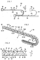
- FIG. 2 shows a section of the cable duct 98 Drag chain 90 in perspective view and in larger Scale and you can see that from a number of articulated interconnected chain links 10,30 or 80,30 formed Obertrum 91 and the bow 92 and the adjoining one Untertrum 93.
- the special training of the individual Chain links 10 and 30 and 80 respectively are shown below described in connection with Figures 3 to 6 in detail.
- Figure 2 are in the longitudinal direction the drag chain 90 seen on individual chain links 10 and 30 spaced support elements provided, which in the illustrated embodiment as laterally protruding bolts 60.60 '; 61.61'; 62.62 '; 63.63' and 64,64 'are formed.
- Using bolts 60.60 'to 64.64' is the drag chain 90 in a suitably designed Support and guide device 65 mounted linearly.
- the device 65 is used in conjunction with FIGS and 9 still described.
- FIG 4 is spatially and on a larger scale in Figure 2 by a circle K designated section in the direction of movement X, X 'slidable drag chain.
- 90 and one recognizes two spaced-apart first ones Chain links 10 and the interposed and articulated with the first two chain links 10 operatively connected second chain link 30.
- the individual chain links 10 and 30 are designed and connected to each other so that in this position (Fig.4) oriented in the longitudinal direction and by correspondingly arranged opposite side walls 20.40 and flanges 22.42 and through the cover plates 15.35 and base plates 16.36 largely closed cable duct 98 form.
- the further design of the two in essentially mirror-image chain links 10 and 30 will be described below in connection with Fig.5.
- FIG 5 is a spatial view and as an exploded view the first chain link 10 and the second chain link 30 for the drag chain 90 is shown.
- the first chain link 10 is essentially Profile-shaped in profile cross-section and includes the top cover plate 15 which is spaced in parallel for this purpose arranged base plate 16 and the cover plate 15 with the base plate 16 connecting first side wall 20.
- the one oriented vertically downward from the cover plate 15 first side wall 20 has one with respect to the bottom plate 16 wall section oriented vertically downwards 20 '.
- the leg 19 is analogous to the leg shown 19 'trained.
- At a parallel distance from the partially Wall section 20 'shown is on the opposite Side one connected to the base plate 16 and vertically downwardly oriented second side wall 21 is arranged.
- the on one side through the side wall 20 with each other connected cover plate 15 and bottom plate 16 are so in Spaced from each other that between the parts 15 and 16 a pocket 18 is provided.
- the one on the side wall 20 molded cover plate 15 has two tapered trained side edges 12 and 13, which by an orthogonal facing end edge 11 are limited.
- the Front edge 11 is preferably rounded 11 'and 11 " Mistake.
- first chain link 10 At one end of the first chain link 10 are essentially in extension of the two parallel spaced side walls 20, 20 'and 21 each two also in parallel First flanges 22, 22 'arranged at a distance from one another, one flange 22 'one on the second side wall 21 has molded leg 19 '.
- the two first flanges 22, 22 'are each formed by a bore 25 or 25 'penetrated.
- Chain link 10 becomes the second with a pivot pin 46 provided chain link 30, the bores 25, 25 'and the pivot pin 46 in assembled a second Form pivot axis B, B '(Fig.4).
- first chain link 10 At the other end of the first chain link 10 are two in second flanges arranged parallel to each other 27,27 'arranged.
- the second flanges 27, 27 ' are on that one end each with a beveled web surface 28, 28 ' and with a face edge 29, 29 'oriented perpendicularly thereto Mistake.
- FIG. 5 For example extending over the entire width of the base plate 16 Hinge pin 26, which is in axial extension on both sides with one with respect to the side walls 21 and 20 projecting, unspecified end piece is.
- the one with the two end pieces protruding to the side provided pivot pin 26 forms a first pivot axis A. for the next with correspondingly arranged bores 45 and 45 'provided second chain link 30 (Fig.4).
- the pivot pin 26 is integrally formed on the base plate 16, the Transition from the flat base plate 16 to the pivot pin 26 with one across the entire, transverse to the direction of movement oriented width of the base plate 16 extending sliding edge 17 is provided.
- the beveled in the direction of movement Sliding edge 17 is used in particular in the bent state Drag chain 90 (Fig.2) as a sliding surface for the individual or for the individual in the form of an electrical cable and / or a hose and arranged in the cable duct 98 Line members 110 (Fig.1).
- the second chain link 30, also shown in FIG. 5, is essentially analogous to the chain link described above 10 formed in the cross section of a ⁇ -shape.
- the second chain link 30 includes the top cover plate 35 which base plate 36 arranged at a parallel distance therefrom and that connects the cover plate 35 to the base plate 36 first side wall 40. Between the cover and base plate 35 and 36 a pocket 38 is provided.
- the from the cover plate 35 oriented vertically downwards to the base plate 36 first side wall 40 has one with respect to bottom plate 36 wall section 40 'oriented vertically downwards.
- At the not designated outside of the side wall 40 and the Wall portion 40 ' is a recess formed recess 34 provided, which by a vertical web 34 ' and delimits a leg 39 arranged orthogonally thereto is.
- the cover plate 35 provided with two tapered side edges 32 and 33, which is oriented by a parallel to the side wall 40 End face 31 are limited.
- the end face 31 is preferably analogous to the first chain link 10 with roundings 31 'and 31 "provided.
- the second chain link 30 At one end of the second chain link 30 are essentially in the extension of the parallel spaced side walls 40, 40 'and 41 two arranged at a parallel distance from one another arranged first flanges 42,42 ', the one Flange 42 extending in the longitudinal direction of the chain link 30 Has leg 39.
- the leg 39 of the second Chain link 30 corresponds approximately to that on the first chain link 10 arranged, not shown legs 19.
- the first chain link 10 (FIG. 4) engages with the pivot pin 26 stored.
- the second chain link 30 At the other end of the second chain link 30 are also two flanges arranged parallel to each other 47,47 'arranged.
- the two second flanges 47.47 ' are at one end each with a bevelled web surface 48.48 'and with a perpendicularly oriented Front edge 49.49 'provided.
- Hinge pin 46 forms a pivot axis B 'for the next mounted on it and with appropriately arranged holes 25, 25 'provided chain link 10.
- the pivot pin 46 is on the bottom plate 36 integrally formed, the transition from the flat bottom plate 36 to the hinge pin 46 with one over the entire, oriented transversely to the direction of movement Width of the base plate 36 extending sliding edge 37 is provided is.
- the beveled in the direction of movement Sliding edge 37 is used in particular in the bent state Drag chain 90 (Fig.2) as a sliding surface for the individual or for the individual in the form of an electrical cable and / or a hose and arranged in the cable duct 98 Line members 110 (Fig.1).
- the two Chain links 10 and 30 essentially analog and mirror images are trained.
- the first chain link 10 in Fig.5 not shown side wall 20,20 'with the Recess 14, the web 14 'and the leg 19 is analog the side wall 40, 40 'shown in FIG the recess 34, the web 34 'and the leg 39 of the second Chain link 30 formed.
- the second chain link 30 with side wall 41 not shown in FIG the leg 39 ' is analogous to that shown in FIG. 5 in view Side wall 21 with the leg 19 'of the first chain link 10 trained.
- the first are Flanges 22,22 'of the first chain link 10 and the second Flanges 47, 47 'of the second chain link 30 are arranged in this way and spaced from one another transversely to the direction of movement X, X ', that when assembled, the second, inner Flanges 47,47 'of the second chain link 30 on the inside arranged between the two spaced side walls 20 'and 21 are.
- the first two outer flanges 22, 22 ' of the first chain link 10 are on the outside of the Side walls 40, 40 and 41 arranged. Is in this position the pivot pin 46 of the second chain link 30 in the bores 25,25 'of the first chain link 10 mounted in a snap.
- Fig. 6 shows a second embodiment as a whole designated with 80 and as a spatial explosive drawing as well as a chain link shown on a larger scale.
- the chain link 80 is formed in two parts and includes a base 80 'and one relative to it, i.e., can be moved transversely to the direction of movement of the drag chain Top 80 ".
- the upper part is approximately perennial-shaped in profile cross-section 80 "has an upper cover plate 73, one at a parallel distance arranged sliding piece 76 and one of the parts 73 and 76 connecting side wall 70. That of the cover plate 73 has side wall 70 oriented vertically downwards a recess 74 formed by a Web 74 'is limited.
- the molded on the side wall 70 Cover plate 73 has two tapered side edges 72.72 ', which is rounded at the front end by a 71 ', 71 "end edge 71 are limited.
- the lower part 80 ' has a base plate 75, which by a Recess 75 'oriented transversely to the direction of movement X, X' in two sections 76 'and 76' is divided. On the two On each side of the recess 75 'there is a beveled one Flank 77 'and 78' provided. On the base plate 75 are also two side walls spaced apart 81 and 81 'molded. At one end of the lower part 80 'are an extension of the two parallel spaced Sidewalls 81,81 'two each also in parallel First flanges 82, 82 'arranged at a distance from one another, one flange 82 'one on the side wall 81 has adjoining leg 79 '.
- the first two flanges 82,82 ' are tapered at one end Web surface 83,83 'and one arranged perpendicular to it End edge 84.84 'provided.
- the first two flanges 82,82 ' are each from a bore 85 and 85 'permeated.
- the next chain link with a pivot pin (not shown) stored.
- the holes 85,85 ' form with the pivot pin of the next chain link, not shown together a swivel axis E.
- the base 80 At the other end of the base 80 'are two in parallel Flanges 87, 87 'arranged at a distance from one another.
- Farther can be seen in Figure 6, for example, over the entire Width of the base plate 75 extending hinge pin 86, which is in axial extension on both sides with one projecting with respect to the side walls 81 and 81 ', unspecified end piece is provided.
- the one with the articulated pins provided on both laterally projecting end pieces 86 accordingly forms a pivot axis F for the next one arranged holes provided chain link.
- the pivot pin 86 is integrally formed on the base plate 75, the Transition from the flat base plate 75 to the pivot pin 86 with one across the entire, transverse to the direction of transport oriented width of the base plate 75 extending sliding edge 86 'is provided
- A can also be on the sliding piece 76 Stop (not shown) are provided so that the Upper part 80 "only up to the stop from the recess 75 'of Lower part 80 'can be pulled out.
- a not shown Be arranged locking element by means of which the upper part 80 " when pushed together against unintentional pulling out is held on the lower part 80 '.
- connection between the two slidable relative to each other Sharing 80 'and 80 can also have one in itself known tongue and groove connection or the like. Essential it is here that the upper part 80 "with the sliding piece 76 relative to that provided with the recess 75 ' Lower part 80 'is slidable and pushed together State of the two parts 80 ', 80 "a flat base plate 75 is formed.
- Fig. 7 shows on a larger scale and in spatial representation the bow piece 92 and a portion of each Upper run 91 and lower run 93 of the drag chain 90 and one can see that in the area of the upper run 91 with the gap-shaped distance C and C 'arranged first and second chain links to each other 10 and 30.
- the individual chain links 10, 30 become motion in this way pivoted to each other, that between them not here specified side edges of the individual chain links 10.30 the gap-like distances C and C 'into gap-like distances D and D' as well Increase D ".
- the gap-shaped distances D" are largest, so that here the line member 110, as in FIG.
- the two outer flanges 22 and 22 'of the first chain link are in the one direction of movement by the assigned Limits 39 and 39 'of the second chain link 30 limited such that the individual chain links 10 and 30 to each other is prevented and the drag chain 90 inevitably can be deflected only in the form of the curved part 92.
- the individual elements of the two chain links 10 and 30 according to 4 to 5 each form a structural unit, the chain links 10 and 30, for example, from a suitable Plastic are injection molded. That in essential two-part chain link 80 according to Fig. 6 is also made of a suitable plastic by spraying manufactured.
- FIG 8 shows a guide rail shown in side view 50 for a sectional view shown in FIG trained to support the drag chain 90 and Guide device 65.
- the support and guide device 65 includes two with the open side against each other as well as in parallel distance to each other and in profile cross-section essentially ⁇ -shaped guide rails 50 and 50 '.
- the guide rails 50 and 50 'each have two in the vertical direction by one in the longitudinal direction Guide groove 52,52 'spaced flanges 51,51' and 53, 53 'and a web 54 connecting them to one another, 54 '.
- the lower flange 53, 53 'of the two are mutually arranged guide rails 50 and 50 ' for example, depending on the length, a number in Recesses 55, 56 and 57 spaced in the longitudinal direction are provided.
- the recesses 55, 56 and 57 are designed such that on the individual chain links 10.30 the Drag chain 90 arranged and on the lower flange 53 and 53 'overlying bolts 60 and 60', such as in Fig.9 shown at any point out of engagement of the can be brought both guide rails 50 and 50 '.
- This measure can be used in the support and guide device 65 guided drag chain 90 at any point by an arcuate deflection out of engagement of the brought both guide rails 50 and 50 '.
- the line members 110 individually or by appropriate Means bundled in the drag chain 90 threaded or stored and in the longitudinal direction thereof on at least one the bottom plates 16 and 36 of the chain links 10 and 30 attached.
- Individual base plates are for this work process with correspondingly designed recesses, not shown or provide openings. After threading and inserting of the line members 110, these are tightened in the longitudinal direction, so that this in the cable duct 98 of the drag chain 90 form a substantially straight line and approximately parallel are arranged to each other.
Abstract
Description
Die Erfindung bezieht sich auf eine Schleppkette mit mehreren gelenkig miteinander verbundenen ersten und zweiten Kettengliedern, welche im Profilquerschnitt etwa ⊂-förmig ausgebildet und zusammen einen in Längsrichtung der Schleppkette orientierten Kabelkanal zur Aufnahme mindestens eines Leitungsgliedes bilden, mittels welchem einer relativ zu einer Energiequelle linear hin- und herbeweglichen Verbrauchereinheit Energie zuführbar ist. Weiterhin betrifft die Erfindung ein Arbeitsverfahren zum Einlegen des Leitungsgliedes in die Schleppkette.The invention relates to a drag chain with several articulated first and second chain links, which is approximately ⊂-shaped in profile cross section and together one in the longitudinal direction of the drag chain oriented cable duct for receiving at least one Form line member, by means of which one relative to an energy source linearly reciprocating consumer unit Energy can be supplied. The invention further relates to a working procedure for inserting the line member in the drag chain.
Zum Zuführen elektrischer, pneumatischer und/oder hydraulischer
Energie zu einer relativ zu einer Energiequelle hin-
und herbeweglichen Verbrauchereinheit sind Schleppketten allgemein
bekannt (Energiekette, Prospekt Seite 21, igus®). Derartige Schleppketten, welche auch als sogenannte
Energieketten, insbesondere in Verbindung mit der
Handhabungstechnik bekannt sind, können in Abhängigkeit der
Anwendung, beispielsweise bei verhältnismässig kurzen Verfahrwegen,
freitragend ausgebildet sein oder aber bei verhältnismässig
langen Verfahrwegen gleitend in einer Führungsrinne
oder auf einem Auflageelement angeordnet werden. Die
einzelne Schleppkette umfasst eine Anzahl gelenkig miteinander
verbundene Kettenglieder, die zusammen einen in Längsrichtung
der Schleppkette orientierten Kabelkanal bilden,
welcher zur Aufnahme mindestens einer elektrischen Leitung
und/oder zur Aufnahme mindestens eines Schlauches für die
pneumatische und/oder hydraulische Energieversorung der Verbrauchereinheit
ausgebildet ist.For feeding electrical, pneumatic and / or hydraulic
Energy towards a relative to an energy source
and mobile consumer unit, drag chains are common
known (energy chain,
Bei den bekannten Schleppketten ist jedes einzelne Kettenglied zum Öffnen und Verschliessen des Kabelkanals mit einer quer zur Bewegungsrichtung aufklappbar an der einen Seite des Kettengliedes angelenkten Abdeckplatte versehen, welche Abdeckplatten nach dem Einlegen der Leitungen und/oder Schläuche einzeln und manuell mit der gegenüberliegenden Seite des Kettengliedes einrastend in Eingriff gebracht werden müssen. Bei einer weiteren Variante kann der Kabelkanal durch eine Vielzahl gelenkig miteinander verbundener Abdeckplatten als sogenanntes endloses Abdeckband, welches in Längsrichtung auf die Kettenglieder aufgelegt und an beiden Seiten des einzelnen Kettengliedes durch Druck schnappartig einrastet, verschlossen werden. Bei den bekannten Schleppketten besteht sowohl das Problem der Fertigung als auch der zeitaufwendigen Montage. Weiterhin besteht bei diesen Schleppketten die Möglichkeit, dass die einzelnen Abdeckplatten, insbesondere aber durch die den lichten Raum des Kabelkanals ausfüllenden Leitungen oder Schläuche, bei den relativ hohen Verfahrgeschwindigkeiten aufgesprengt werden und somit ein einwandfreier Betrieb nicht gewährleistet ist.In the known drag chains, every single link is for opening and closing the cable duct with a Can be opened transversely to the direction of movement on one side of the Chain link hinged cover plate, which cover plates after inserting the lines and / or hoses individually and manually with the opposite side of the Chain link must be brought into engagement. In a further variant, the cable duct can be separated by a Large number of hinged cover plates as so-called endless masking tape, which in the longitudinal direction the chain links put on and on both sides of the individual Chain link snaps into place by pressure, closed become. In the known drag chains there is both the problem of manufacturing as well as the time consuming Assembly. With these drag chains, there is also the option of that the individual cover plates, but in particular through the lines filling the clear space of the cable duct or hoses at the relatively high travel speeds be blown up and thus a flawless Operation is not guaranteed.
Aus der GB-A 1,012,432 ist weiterhin eine aus einer Vielzahl von Kettengliedern gebildete und mit einem Kanal zur Aufnahme eines Kabels und/oder eines Schlauches versehene Schleppkette bekannt, bei welcher die einzelnen im Profilquerschnitt etwa, ⊂-förmig ausgebildeten Kettenglieder an der einen quer zur Längsrichtung der Schleppkette orientierten Seite miteinander gelenkig verbunden und an der gegenüberliegenden Seite zum Einlegen des Kabels oder Schlauches jeweils mit einem herausnehmbaren und wieder einsetzbaren Bolzen versehen sind.GB-A 1,012,432 is still one of a large number formed by chain links and with a channel for receiving a drag chain provided with a cable and / or a hose known, in which the individual in the profile cross section, ⊂-shaped chain links on one across Longitudinal direction of the drag chain side with each other articulated and on the opposite side to the Insert the cable or hose with one each removable and reusable bolts are provided.
Der Erfindung liegt die Aufgabe zugrunde die Herstellung der einzelnen Kettenglieder für eine Schleppkette der genannten Art zu verbessern und diese derart auszubilden, dass sowohl ein rasches Montieren (Einlegen) der Leitungsglieder in den Kabelkanal gewährleistet sowie ein rasches Demontieren (Entfernen) der Leitungsglieder ohne zusätzliche Hilfsmittel möglich ist.The invention has for its object the manufacture of individual chain links for a drag chain of the above Art to improve and train them in such a way that both rapid assembly (insertion) of the line elements in the Cable duct ensures and quick disassembly (Removal) of the line elements possible without additional aids is.
Die Aufgabe wird erfindungsgemäss dadurch gelöst, dass die jeweils mit einer Seitenwand, einer daran angeordneten Abdeckplatte und einer in parallelem Abstand dazu angeordneten Bodenplatte versehenen Kettenglieder jeweils mit den Seitenwänden in bezug auf die Längs- und Bewegungsrichtung der Schleppkette abwechselnd auf der einen oder anderen Seite derselben angeordnet sind, und dass zwischen den etwa quer zur Bewegungsrichtung orientierten und einander zugewandten Seitenkanten der Abdeckplatten jeweils ein spaltförmiger Abstand vorgesehen ist, wobei der spaltförmige Abstand bei der bogenförmigen Umlenkung der Schleppkette durch die Relativbewegung der miteinander verbundenen Kettenglieder hinsichtlich der Spaltbreite vergrössert wird und bei geradlinig gestreckter Schleppkette auf die ursprünglich gewählte Spaltbreite zurückführbar ist.The object is achieved in that the each with a side wall, a cover plate arranged thereon and one arranged parallel to it Chain links provided with the bottom plate each with the side walls with respect to the longitudinal and direction of movement of the Drag chain alternately on one side or the other the same are arranged, and that between the approximately transverse oriented to the direction of movement and facing each other Side edges of the cover plates each a gap-shaped distance is provided, the gap-shaped distance at curved deflection of the drag chain by the relative movement the interconnected chain links with regard the gap width is increased and in a straight line Drag chain to the originally selected gap width is traceable.
Ein wesentlicher Vorteil der Erfindung wird in der wirtschaftlichen Montage und Demontage des oder der Leitungsglieder gesehen, weil bei der erfindungsgemässen Schleppkette das zeitraubende Verschliessen der einzelnen Kettenglieder mittels der einzelnen, klappbar angelenkten Abdeckplatten nicht mehr erforderlich ist. Zudem ist ein unerwünschtes Aufspringen der Abdeckelemente während des Betriebes ausgeschlossen.A major advantage of the invention is in the economic Assembly and disassembly of the line member (s) seen because in the drag chain according to the invention time-consuming closing of the individual chain links using of the individual hinged cover plates not more is needed. In addition, an undesirable popping open the cover elements excluded during operation.
Das erfindungsgemässe Arbeitsverfahren zum Einlegen mindestens eines Leitungsgliedes in die Schleppkette ist dadurch gekennzeichnet, dass das einzelne Leitungsglied im Bereich des Bogenteils in Bewegungsrichtung abwechselnd von der einen und anderen Seite der Schleppkette eingefädelt und im Kabelkanal abgelegt wird. The working method according to the invention for inserting at least is a link in the drag chain characterized that the single line member in the area of the arc part alternately in the direction of movement from one and other side of the drag chain and threaded in the cable duct is filed.
In einer weiteren Ausgestaltung wird vorgeschlagen, bei der aus mehreren gelenkig miteinander verbundenen ersten und zweiten Kettengliedern bestehenden Schleppkette, das einzelne Kettenglied mit einem ersten und zweiten Teilstück etwa zweiteilig auszubilden, wobei die als erstes Teilstück ausgebildeten Oberteile bei welcher die ersten Teilstücke in bezug auf die gelenkig miteinander verbundenen und als Unterteil ausgebildeten zweiten Teilstücke relativ und quer zur Längsrichtung der Schleppkette verschiebbar ausgebildet sind.In a further embodiment, it is proposed that of several first and second chain links existing drag chain, the single Chain link with a first and second section approximately in two parts to train, the trained as the first section Tops with which the first sections are related on the articulated and as a lower part trained second sections relative and transverse to the longitudinal direction the drag chain are slidable.
Im Rahmen der Erfindung liegt es weiterhin, für verhältnismässig lange Schleppketten eine Führungsvorrichtung anzugeben, mittels welcher unter Beibehaltung einer Umlenkung an beliebiger Stelle ein Durchhängen verhindert wird. Die Führungsvorrichtung für die erfindungsgemässe Schleppkette ist dadurch gekennzeichnet, dass die Schleppkette mit in Längsrichtung verteilt zueinander angeordneten und seitlich abstehend ausgebildeten Bolzen zwischen zwei in parallelem Abstand zueinander angeordneten und im Profilquerschnitt etwa ⊂-förmig ausgebildeten sowie gegenläufig zueinander angeordneten Führungsschienen gelagert ist, wobei im unteren Flansch der Führungsschienen mehrere in Längsrichtung im Abstand zueinander angeordnete Ausnehmungen vorgesehen sind, durch welche die zwischen den Führungsschienen angeordnete Schleppkette nach unten auslenkbar ist.It is also within the scope of the invention, for proportionate long drag chains to specify a guide device by means of which while maintaining a redirection sagging is prevented at any point. The guide device for the drag chain according to the invention characterized in that the drag chain with in the longitudinal direction distributed to each other and laterally protruding trained bolts between two at a parallel distance arranged in relation to each other and approximately ⊂-shaped in cross-section trained and arranged in opposite directions to each other Guide rails is mounted, with in the lower flange Guide rails several in the longitudinal direction at a distance from each other arranged recesses are provided through which the drag chain arranged between the guide rails is deflectable downwards.
Weitere zweckmässige Ausgestaltungen und Einzelheiten sowie Vorteile der Erfindung ergeben sich aus der folgenden Beschreibung in Verbindung mit der Zeichnung und den einzelnen Patentansprüchen.Further expedient configurations and details as well Advantages of the invention result from the following description in connection with the drawing and the individual Claims.
Anhand der Zeichnung werden nachstehend einzelne Ausführungsbeispiele
der Erfindung beschrieben. Es zeigt:
Fig.1 zeigt zur Verdeutlichung der Erfindung eine schematisch
dargestellte Vorrichtung 100, welche im wesentlichen eine in
der Gesamtheit mit 90 bezeichnete Schleppkette, eine
Verbrauchereinheit 95, ein Auflage- und Führungselement 96
für die Schleppkette 90 sowie eine Energiequelle 97 umfasst.
Im dargestellten Ausführungs- und Anwendungsbeispiel hat die
Schleppkette 90 ein Obertrum 91, ein Bogenteil 92 und ein Untertrum
93. Weiterhin ist die Schleppkette 90 mit einem ersten
Anschlussstück 94 an der Verbrauchereinheit 95 und mit
einem zweiten Anschlussstück 94' in nicht näher dargestellter
Weise entweder im Bereich der Energiequelle 97 an dem Auflage-
und Führungselement 96 oder direkt an der Energiequelle
angeordnet. Die beiden Anschlussstücke 94 und 94' sind jeweils
an den beiden Enden der Schleppkette 90 mit nicht näher
dargestellten Mitteln befestigt.1 shows a schematic to illustrate the
Zur Verdeutlichung des Bewegungsablaufs der auf dem Auflage-
und Führungselement 96 im wesentlichen abrollend aufliegenden
Schleppkette 90 ist diese in Fig.1 beispielsweise in zwei
Stellungen dargestellt. Bei der in Pfeilrichtung X' orientierten
Bewegung hat die Schleppkette 90 zusammen mit der
Verbrauchereinheit 95, wie durch die unterbrochen (gestrichelt)
eingezeichneten Linien dargestellt, etwa die Endstellung
erreicht. Bei der in Pfeilrichtung X orientierten Bewegung
hat die mit der Verbrauchereinheit 95 wirkverbundene
Schleppkette 90, wie durch die voll eingezeichneten Linien
dargestellt, die Endstellung noch nicht ganz erreicht.To clarify the course of movement of the
and
Die einzelnen, in Fig.1 nicht näher dargestellten Kettenglieder
der Schleppkette 90 bilden zusammen einen in Längsrichtung
derselben orientierten Kabelkanal 98 zur Aufnahme mindestens
eines in Fig.1 teilweise dargestellten Leitungsgliedes
110. Der Kabelkanal 98 ist jedoch vorzugsweise zur Aufnahme
mehrerer Leitungsglieder 110 ausgebildet. Die einzelnen in
den Kabelkanal 98 einlegbaren und einerseits mit der zugeordneten
Energiequelle 97 und andererseits mit der Verbrauchereinheit
95 wirkverbundenen Leitungsglieder 110 können dabei
in Form eines Kabels für die elektrische Energieversorgung
der Verbrauchereinheit und/oder in Form eines flexiblen
Schlauches für die pneumatische und/oder hydraulische Energieversorgung
der Verbrauchereinheit 95 ausgebildet sein.The individual chain links, not shown in Figure 1
the
Die Aufnahme und Unterbringung einer aus mehreren elektrischen,
pneumatischen und/oder hydraulischen Leitungsgliedern
110 bestehenden Kombination in die Schleppkette 90 ist ebenfalls
möglich. Die erfindungsgemässe Schleppkette 90 mit den
darin in Längsrichtung angeordneten Leitungsgliedern 110 gewährleistet
bei der in bezug auf die feststehende Energiequelle
97 in Längsrichtung gemäss Pfeilrichtung X und X' orientierten
Hin- und Herbewegung der Verbrauchereinheit 95 sowie
der dabei im Kabelkanal 98 erfolgenden Abrollbewegung der
einzelnen Leitungsglieder 110 einen störungsfreien Betrieb.
Der störungsfreie Betrieb ist auch bei verhältnismässig langen
oder kurzen Bewegungsabläufen zwischen der feststehenden
Energiequelle 97 und der Verbrauchereinheit 95 und auch bei
relativ hohen Geschwindigkeiten der Hin- und Herbewegungen
gewährleistet.The accommodation and placement of one of several electrical,
pneumatic and / or
Fig.2 zeigt ein Teilstück der mit dem Kabelkanal 98 versehenen
Schleppkette 90 in perspektivischer Ansicht und in grösserem
Massstab und man erkennt das aus einer Anzahl gelenkig
miteinander verbundener Kettenglieder 10,30 oder 80,30 gebildete
Obertrum 91 sowie den Bogen 92 und das daran anschliessende
Untertrum 93. Die besondere Ausbildung der einzelnen
Kettenglieder 10 und 30 beziehungsweise 80 wird nachstehend
in Verbindung mit den Figuren 3 bis 6 im einzelnen beschrieben.
Wie in Fig.2 schematisch dargestellt, sind in Längsrichtung
der Schleppkette 90 gesehen an einzelnen Kettengliedern
10 und 30 im Abstand zueinander angeordnete Auflageelemente
vorgesehen, welche im dargestellten Ausführungsbeispiel als
seitlich abstehende Bolzen 60,60';61,61'; 62,62';63,63' und
64,64' ausgebildet sind. Mittels der Bolzen 60,60' bis 64,64'
ist die Schleppkette 90 in einer entsprechend ausgebildeten
Abstütz- und Führungsvorrichtung 65 linear verschiebbar gelagert.
Die Vorrichtung 65 wird in Verbindung mit den Figuren 8
und 9 noch beschrieben.2 shows a section of the
In Fig.3 ist ein Teilstück der aus den einzelnen gelenkig
miteinander verbundenen ersten Kettenglieder 10 und zweiten
Kettengliedern 30 gebildeten Schleppkette 90 in Draufsicht
dargestellt und man erkennt die in parallelem Abstand C und
C' zueinander angeordnete Abdeckplatten 15 und 35 der einzelnen
Kettenglieder 10 und 30. Zur Erreichung der spaltförmig ausgebildeten Abstande C
und C' sind die Abdeckplatten 15 der ersten Kettenglieder 10
ausgehend von einer in Fig.3 nicht näher dargestellten Seitenwand
20 und die Abdeckplatten 35 der zweiten Kettenglieder
30 ausgehend von einer gegenüberliegenden Seitenwand 40 jeweils
quer zur Bewegungsrichtung X,X' konisch verjüngend ausgebildet.
Durch diese Formgebung wird erreicht, dass die spaltförmigen Abstände
C und C' in Bewegungsrichtung X,X' der Schleppkette 90
gesehen abwechselnd schräg geneigt zueinander angeordnet
sind. Die korrespondierend gegenüberliegenden Seitenkanten 12
und 32 beziehungsweise 13 und 33 der Abdeckplatten 15,35 sind
in parallelem Abstand zueinander angeordnet. Die durch die
besondere Ausbildung und Anordnung der Abdeckplatten 15 und
35 der Kettenglieder 10 und 30 erreichbaren Montagevorteile
für die einlegbaren Leitungsglieder 110 werden in Verbindung
mit Fig.7 noch im einzelnen beschrieben.In Figure 3, a portion of the individual is articulated
interconnected
In Fig.4 ist räumlich und in grösserem Massstab ein in Fig.2
durch einen Kreis K bezeichnetes Teilstück der in Bewegungsrichtung
X,X' verschiebbaren Schleppkette. 90 dargestellt und
man erkennt zwei im Abstand zueinander angeordnete erste
Kettenglieder 10 sowie das dazwischen angeordnete und gelenkig
mit den beiden ersten Kettengliedern 10 wirkverbundene
zweite Kettenglied 30. Die einzelnen Kettenglieder 10 und 30
sind derart ausgebildet und miteinander verbunden, dass diese
in dieser Position (Fig.4) den in Längsrichtung orientierten
und durch entsprechend gegenüberliegend angeordnete Seitenwände
20,40 und Flanschen 22,42 sowie durch die Abdeckplatten
15,35 und Bodenplatten 16,36 weitgehend geschlossenen Kabelkanal
98 bilden. Die weitere Ausgestaltung der beiden im
wesentlichen spiegelbildlich ausgebildeten Kettenglieder 10
und 30 wird nachstehend in Verbindung mit Fig.5 beschrieben.In Figure 4 is spatially and on a larger scale in Figure 2
by a circle K designated section in the direction of movement
X, X 'slidable drag chain. 90 and
one recognizes two spaced-apart first
In Fig.5 ist in räumlicher Ansicht und als Sprengzeichnung
das erste Kettenglied 10 sowie das zweite Kettenglied 30 für
die Schleppkette 90 dargestellt. Das erste Kettenglied 10 ist
im Profilquerschnitt im wesentlichen ⊃-förmig ausgebildet
und umfasst die obere Abdeckplatte 15, die in parallelem Abstand
dazu angeordnete Bodenplatte 16 sowie die die Abdeckplatte
15 mit der Bodenplatte 16 verbindende erste Seitenwand
20. Die von der Abdeckplatte 15 senkrecht nach unten orientierte
erste Seitenwand 20 hat ein in bezug auf die Bodenplatte
16 senkrecht nach unten orientiertes Wandteilstück
20'. An der nicht bezeichneten Aussenseite der Seitenwand 20
und des angeformten Wandteilstücks 20' ist eine abgesetzt
ausgebildete Ausnehmung 14 vorgesehen, welche einerseits
durch einen senkrechten Steg 14' sowie durch einen orthogonal
dazu angeordneten Schenkel 19 begrenzt ist (nicht dargestellt).
Der Schenkel 19 ist analog dem dargestellten Schenkel
19' ausgebildet. In parallelem Abstand zu dem teilweise
dargestellten Wandteilstück 20' ist an der gegenüberliegenden
Seite eine an der Bodenplatte 16 anschliessende und senkrecht
nach unten orientierte zweite Seitenwand 21 angeordnet. Die
auf der einen Seite durch die Seitenwand 20 miteinander
verbundene Abdeckplatte 15 und Bodenplatte 16 sind derart im
Abstand zueinander angeordnet, dass zwischen den Teilen 15
und 16 eine Tasche 18 vorgesehen ist. Die an der Seitenwand
20 angeformte Abdeckplatte 15 hat zwei verjüngend
ausgebildete Seitenkanten 12 und 13, welche durch eine orthogonal
dazu orientierte Stirnkante 11 begrenzt sind. Die
Stirnkante 11 ist vorzugsweise mit Abrundungen 11' und 11"
versehen. In Figure 5 is a spatial view and as an exploded view
the
An dem einen Ende des ersten Kettengliedes 10 sind im wesentlichen
in Verlängerung der beiden parallel beabstandeten Seitenwände
20,20' und 21 jeweils zwei ebenfalls in parallelem
Abstand zueinander angeordnete erste Flanschen 22,22' angeordnet,
wobei der eine Flansch 22' einen an der zweiten Seitenwand
21 anliegend angeformten Schenkel 19' aufweist. Die
beiden ersten Flanschen 22,22' sind an dem einen Ende jeweils
mit einer abgeschrägten Stegfläche 23,23' sowie einer senkrecht
dazu angeordneten Stirnkante 24,24' versehen. Die beiden
ersten Flanschen 22,22' werden jeweils von einer Bohrung
25 beziehungsweise 25' durchdrungen. In den beiden korrespondierend
zueinander angeordneten Bohrungen 25 und 25' des ersten
Kettengliedes 10 wird das zweite mit einem Gelenkzapfen
46 versehene Kettenglied 30 gelagert, wobei die Bohrungen
25,25' und der Gelenkzapfen 46 in zusammengebautem eine zweite
Schwenkachse B,B' bilden (Fig.4).At one end of the
An dem anderen Ende des ersten Kettengliedes 10 sind zwei in
parallelem Abstand zueinander angeordnete zweite Flanschen
27,27' angeordnet. Die zweiten Flanschen 27,27' sind an dem
einen Ende jeweils mit einer abgeschrägten Stegfläche 28,28'
sowie mit einer senkrecht dazu orientierten Stirnkante 29,29'
versehen. Weiterhin erkennt man in Fig.5 einen sich beispielsweise
über die gesamte Breite der Bodenplatte 16 erstreckenden
Gelenkzapfen 26, welcher in axialer Verlängerung
an beiden Seiten mit einem in bezug auf die Seitenwände 21
und 20 abstehenden, nicht näher bezeichneten Endstück versehen
ist. Der mit den beiden seitlich abstehenden Endstücken
versehene Gelenkzapfen 26 bildet eine erste Schwenkachse A
für das nächste mit entsprechend angeordneten Bohrungen 45
und 45' versehene zweite Kettenglied 30 (Fig.4). Der Gelenkzapfen
26 ist an der Bodenplatte 16 angeformt, wobei der
Übergang von der ebenen Bodenplatte 16 zu dem Gelenkzapfen 26
mit einer sich über die gesamte, quer zur Bewegungsrichtung
orientierten Breite der Bodenplatte 16 erstreckenden Gleitkante
17 versehen ist. Die in Bewegungsrichtung angeschrägte
Gleitkante 17 dient insbesondere in abgebogenem Zustand der
Schleppkette 90 (Fig.2) als Gleitfläche für das einzelne oder
für die einzelnen in Form eines elektrischen Kabels und/oder
eines Schlauches ausgebildeten und im Kabelkanal 98 angeordneten
Leitungsglieder 110 (Fig.1).At the other end of the
Das ebenfalls in Fig.5 dargestellte zweite Kettenglied 30 ist
im wesentlichen analog dem vorstehend beschriebenen Kettenglied
10 im Profilquerschnitt ⊂-förmig ausgebildet. Das
zweite Kettenglied 30 umfasst die obere Abdeckplatte 35, die
in parallelem Abstand dazu angeordnete Bodenplatte 36 sowie
die die Abdeckplatte 35 mit der Bodenplatte 36 verbindende
erste Seitenwand 40. Zwischen der Abdeck- und Bodenplatte 35
und 36 ist eine Tasche 38 vorgesehen. Die von der Abdeckplatte
35 senkrecht nach unten zur Bodenplatte 36 orientierte
erste Seitenwand 40 hat ein in bezug auf die Bodenplatte 36
senkrecht nach unten orientiertes Wandteilstück 40'. An der
nicht bezeichneten Aussenseite der Seitenwand 40 und des
Wandteilstückes 40' ist eine abgesetzt ausgebildete Ausnehmung
34 vorgesehen, welche durch einen senkrechten Steg 34'
und einen orthogonal dazu angeordneten Schenkel 39 begrenzt
ist. In parallelem Abstand zu dem Wandteilstück 40' ist an
der gegenüberliegenden Seite eine an der Bodenplatte 36 anschliessende
und senkrecht nach unten orientierte zweite Seitenwand
41 angeordnet, welche in Fig.5 nur teilweise sichtbar
ist. Ausgehend von der Seitenwand 40 ist die Abdeckplatte 35
mit zwei verjüngend ausgebildeten Seitenkanten 32 und 33 versehen,
welche durch eine parallel zur Seitenwand 40 orientierte
Stirnseite 31 begrenzt sind. Die Stirnseite 31 ist
vorzugsweise analog dem ersten Kettenglied 10 mit Abrundungen
31' und 31" versehen.The
An dem einen Ende des zweiten Kettengliedes 30 sind im wesentlichen
in Verlängerung der parallel beabstandeten Seitenwände
40,40' und 41 zwei in parallelem Abstand zueinander angeordnete
erste Flanschen 42,42' angeordnet, wobei der eine
Flansch 42 den sich in Längsrichtung des Kettengliedes 30 erstreckenden
Schenkel 39 aufweist. Der Schenkel 39 des zweiten
Kettengliedes 30 entspricht etwa dem am ersten Kettenglied 10
angeordneten, nicht näher dargestellten Schenkel 19. Die
beiden ersten Flanschen 42,42' sind an dem einen Ende jeweils
mit einer abgeschrägten Stegfläche 43,43' sowie einer
senkrecht dazu angeordneten Stirnkante 44,44' versehen. Die
beiden ersten Flanschen 42,42' werden jeweils von einer Bohrung
45 beziehungsweise 45' durchdrungen. In den beiden korrespondierend
zueinander angeordneten Bohrungen 45,45' ist
das erste Kettenglied 10 (Fig.4) mit dem Gelenkzapfen 26 einrastend
gelagert.At one end of the
An dem anderen Ende des zweiten Kettengliedes 30 sind ebenfalls
zwei in parallelem Abstand zueinander angeordnete Flanschen
47,47' angeordnet. Die beiden zweiten Flanschen 47,47'
sind an dem einen Ende jeweils mit einer abgeschrägten Stegfläche
48,48' sowie mit einer senkrecht dazu orientierten
Stirnkante 49,49' versehen. Weiterhin erkennt man in Fig.5
einen teilweise dargestellten, sich über die gesamte Breite
des Kettengliedes 30 erstreckenden Gelenkzapfen 46, welcher
an beiden Seiten ein in bezug auf die Seitenwände 41 und 40
abstehendes, nicht näher bezeichnetes Endstück aufweist. Der
Gelenkzapfen 46 bildet eine Schwenkachse B' für das nächste
daran gelagerte und mit entsprechend angeordneten Bohrungen
25,25' versehene Kettenglied 10. Der Gelenkzapfen 46 ist an
der Bodenplatte 36 angeformt, wobei der Übergang von der
ebenen Bodenplatte 36 zu dem Gelenkzapfen 46 mit einer sich
über die gesamte, quer zur Bewegungsrichtung orientierten
Breite der Bodenplatte 36 erstreckenden Gleitkante 37 versehen
ist. Die in Bewegungsrichtung angeschrägt ausgebildete
Gleitkante 37 dient insbesondere in abgebogenem Zustand der
Schleppkette 90 (Fig.2) als Gleitfläche für das einzelne oder
für die einzelnen in Form eines elektrischen Kabels und/oder
eines Schlauches ausgebildeten und im Kabelkanal 98 angeordneten
Leitungsglieder 110 (Fig.1). At the other end of the
An dieser Stelle wird darauf hingewiesen, dass die beiden
Kettenglieder 10 und 30 im wesentlichen analog und spiegelbildlich
ausgebildet sind. Die bei dem ersten Kettenglied 10
in Fig.5 nicht näher dargestellte Seitenwand 20,20' mit der
Ausnehmung 14, dem Steg 14' und dem Schenkel 19 ist analog
der in Fig.5 in Ansicht dargestellten Seitenwand 40,40' mit
der Ausnehmung 34, dem Steg 34' und dem Schenkel 39 des zweiten
Kettengliedes 30 ausgebildet. Die bei dem zweiten Kettenglied
30 in Fig.5 nicht näher dargestellte Seitenwand 41 mit
dem Schenkel 39' ist analog der in Fig.5 in Ansicht dargestellten
Seitenwand 21 mit dem Schenkel 19' des ersten Kettengliedes
10 ausgebildet.At this point it should be noted that the two
Wie in Fig.4 sowie in Fig.5 dargestellt, sind die ersten
Flanschen 22,22' des ersten Kettengliedes 10 und die zweiten
Flanschen 47,47' des zweiten Kettengliedes 30 derart angeordnet
und quer zur Bewegungsrichtung X,X' zueinander beabstandet,
dass in zusammengebautem Zustand die zweiten, inneren
Flanschen 47,47' des zweiten Kettengliedes 30 innenseitig
zwischen den beiden beabstandeten Seitenwänden 20' und 21 angeordnet
sind. Die beiden ersten, äusseren Flanschen 22,22'
des ersten Kettengliedes 10 sind dabei aussenseitig an den
Seitenwänden 40,40 und 41 angeordnet. In dieser Stellung ist
der Gelenkzapfen 46 des zweiten Kettengliedes 30 in den Bohrungen
25,25' des ersten Kettengliedes 10 einrastend gelagert.As shown in Fig.4 and Fig.5, the first are
Fig.6 zeigt als zweites Ausführungbeispiel ein in der Gesamtheit
mit 80 bezeichnetes und als räumliche Sprengzeichnung
sowie in grösserem Massstab dargestelltes Kettenglied. Abweichend
von dem vorstehend im einzelnen beschriebenen Kettenglied
10 gemäss Fig.5 ist das Kettenglied 80 zweiteilig ausgebildet
und umfasst ein Unterteil 80' und ein relativ dazu,
d.h., quer zur Bewegungsrichtung der Schleppkette verschiebbares
Oberteil 80". Fig. 6 shows a second embodiment as a whole
designated with 80 and as a spatial explosive drawing
as well as a chain link shown on a larger scale. Deviating
of the chain link described in detail above
10 according to Figure 5, the
Das im Profilquerschnitt etwa ⊃-förmig ausgebildete Oberteil
80" hat eine obere Abdeckplatte 73, ein in parallelem Abstand
dazu angeordnetes Schiebestück 76 sowie eine die Teile 73 und
76 miteinander verbindende Seitenwand 70. Die von der Abdeckplatte
73 senkrecht nach unten orientierte Seitenwand 70 hat
eine abgesetzt ausgebildete Ausnehmung 74, welche durch einen
Steg 74' begrenzt ist. Die an der Seitenwand 70 angeformte
Abdeckplatte 73 hat zwei verjüngend ausgebildete Seitenkanten
72,72', welche am vorderen Ende durch eine mit Abrundungen
71',71" versehene Stirnkante 71 begrenzt sind. Im dargestellten
Ausführungsbeispiel sind die quer zur Bewegungsrichtung
X,X' der Schleppkette (nicht dargestellt) orientierten Seitenkanten
77 und 78 des Schiebestücks 76 als abgeschrägte
Flanken ausgebildet (Fig.6).The upper part is approximately etwa-shaped in
Das Unterteil 80' hat eine Bodenplatte 75, welche durch eine
quer zur Bewegungsrichtung X,X' orientierte Ausnehmung 75' in
zwei Teilstücke 76' und 76' unterteilt ist. An den beiden
Seiten der Ausnehmung 75' ist jeweils eine abgeschrägt ausgebildete
Flanke 77' und 78' vorgesehen. An der Bodenplatte 75
sind weiterhin zwei im Abstand zueinander angeordnete Seitenwände
81 und 81' angeformt. An dem einen Ende des Unterteils
80' sind in Verlängerung der beiden parallel beabstandeten
Seitenwände 81,81' jeweils zwei ebenfalls in parallelem
Abstand zueinander angeordnete erste Flanschen 82,82' angeordnet,
wobei der eine Flansch 82' einen an der Seitenwand 81
anliegend angeformten Schenkel 79' aufweist. An dem Flansch
82 ist ebenfalls ein nicht näher dargestellter Schenkel
(analog dem Schenkel 79') angeformt. Die beiden ersten Flanschen
82,82' sind an dem einen Ende jeweils mit einer abgeschrägten
Stegfläche 83,83' sowie einer senkrecht dazu angeordneten
Stirnkante 84,84' versehen. Die beiden ersten Flanschen
82,82' werden jeweils von einer Bohrung 85 beziehungsweise
85' durchdrungen. In den beiden korrespondierend zueinander
angeordneten Bohrungen 85 und 85' des Unterteils 80'
ist das mit einem Gelenkzapfen versehene nächste Kettenglied
(nicht dargestellt) gelagert. Die Bohrungen 85,85' bilden mit
dem Gelenkzapfen des nächsten nicht dargestellten Kettengliedes
zusammen eine Schwenkachse E.The lower part 80 'has a
An dem anderen Ende des Unterteils 80' sind zwei in parallelem
Abstand zueinander angeordnete Flanschen 87,87' angeordnet.
Die Flanschen 87,87' sind an dem einen Ende jeweils mit
einer abgeschrägten Stegfläche 88,88' sowie mit einer senkrecht
dazu orientierten Stirnkante 89,89' versehen. Weiterhin
erkennt man in Fig.6 einen sich beispielsweise über die gesamte
Breite der Bodenplatte 75 erstreckenden Gelenkzapfen
86, welcher in axialer Verlängerung an beiden Seiten mit
einem in bezug auf die Seitenwände 81 und 81' abstehenden,
nicht näher bezeichneten Endstück versehen ist. Der mit den
beiden seitlich abstehenden Endstücken versehene Gelenkzapfen
86 bildet eine Schwenkachse F für das nächste mit entsprechend
angeordneten Bohrungen versehene Kettenglied. Der Gelenkzapfen
86 ist an der Bodenplatte 75 angeformt, wobei der
Übergang von der ebenen Bodenplatte 75 zu dem Gelenkzapfen 86
mit einer sich über die gesamte, quer zur Transportrichtung
orientierten Breite der Bodenplatte 75 erstreckenden Gleitkante
86' versehen ist.At the other end of the base 80 'are two in
Bei dem in Fig.6 dargestellten Ausführungsbeispiel ist das
Oberteil 80" mit dem Schiebestück 76 relativ zu dem mit der
Ausnehmung 75' versehenen Unterteil 80' verschiebbar. Die
beiden Teile 80' und 80" können durch eine sogenannte
"Schwalbenschwanz-Führung" derart miteinander verbunden werden,
dass das in die Ausnehmung 75' einschiebbare Schiebestück
76 des Oberteils 80" mit den beiden Teilstücken 76',76"
in eingeschobenem Zustand (nicht dargestellt) die ebene Bodenplatte
75 bildet. An dem Schiebestück 76 kann zudem ein
Anschlag (nicht dargestellt) vorgesehen werden, so dass das
Oberteil 80" nur bis zum Anschlag aus der Ausnehmung 75' des
Unterteils 80' herausgezogen werden kann. Weiterhin kann an
dem Schiebestück 76 des Oberteils 80" ein nicht dargestelltes
Rastelement angeordnet sein, mittels welchem das Oberteil 80"
in zusammengeschobenem Zustand gegen unbeabsichtigtes Herausziehen
an dem Unterteil 80' gehalten ist.In the exemplary embodiment shown in FIG. 6, this is
Die Verbindung zwischen den beiden relativ zueinander verschiebbaren
Teilen 80' und 80" kann auch über eine an sich
bekannte Nut-Federverbindung oder dergleichen erfolgen. Wesentlich
hierbei ist es, dass das Oberteil 80" mit dem Schiebestück
76 relativ zu dem mit der Ausnehmung 75' versehenen
Unterteil 80' verschiebbar ist und in zusammengeschobenem
Zustand der beiden Teile 80',80" eine ebene Bodenplatte 75
gebildet ist.The connection between the two slidable relative to each
An dieser Stelle wird darauf hingewiesen, dass bei einer aus
den Kettengliedern 80 und spiegelbildlich ausgebildeten Kettenglieder
(nicht dargestellt) bestehenden Schleppkette durch
die quer zur Bewegungsrichtung der Schleppkette relativ zu
den Unterteilen 80' verschiebbaren Oberteile 80" eine verhältnismässig
grosse Öffnung zum Einlegen eines relativ breiten
Leitungsgliedes möglich ist. Das seitliche Herausziehen
der Oberteile 80" erfolgt dabei in gestreckter Lage der
Schleppkette.At this point it should be noted that in the case of an
the chain links 80 and mirror-image chain links
(not shown) existing drag chain
which are transverse to the direction of movement of the drag chain
the lower parts 80 'displaceable
Es besteht weiterhin die Möglichkeit, dass in gestreckter Lage
der abwechselnd aus miteinander gelenkig verbundenen Kettengliedern
80 und 30 sowie 80 gebildeten Schleppkette 90
(Fig.2) nur die einen Kettenglieder 80 mit einem herausziehbaren
Oberteil 80" ausgebildet sind, so dass das Leitungsglied
(nicht dargestellt) etwa analog dem Beispiel gemäss
Fig.7 abwechselnd von der einen und anderen Seite eingefädelt
im Kabelkanal abgelegt wird.There is still the possibility that in a stretched position
the alternating
Fig.7 zeigt in grösserem Massstab sowie in räumlicher Darstellung
das Bogenstück 92 sowie jeweils ein Teilstück des
Obertrums 91 und des Untertrums 93 der Schleppkette 90 und
man erkennt die im Bereich des Obertrums 91 mit dem spaltförmigen Abstand C und
C' zueinander angeordneten ersten und zweiten Kettenglieder
10 und 30. Bei der in Pfeilrichtung X" etwa kreisbogenförmigen
Bewegung werden die einzelnen Kettenglieder 10,30 derart
zueinander verschwenkt, dass dabei zwischen den hier nicht
näher bezeichneten Seitenkanten der einzelnen Kettenglieder
10,30 sich die spaltförmigen Abstände C und C' in spaltförmige Abstände D und D' sowie
D" vergrössern. Im Bogenbereich sind die spaltförmigen Abstände D" am
grössten, so dass hier das Leitungsglied 110, wie in Fig.7
schematisch dargestellt, abwechselnd von der einen und anderen
Seite der Schleppkette 90 eingefädelt und in dem Kabelkanal
98 abgelegt werden kann. Das Einfädeln beziehungsweise
Einlegen des oder der Leitungsglieder 110 erfolgt vorzugsweise
bei gleichzeitiger, abrollender Bewegung der Schleppkette
90 in Pfeilrichtung X".Fig. 7 shows on a larger scale and in spatial representation
the
Die etwa im Bereich des Bogenteils 92 erfolgende Relativbewegung
(Fig.7) der einzelnen Kettenglieder 10 und 30 zueinander
ist im wesentlichen durch die abgeschrägten und mit der nicht
bezeichneten unteren Fläche der Bodenplatte 16 formschlüssig
anliegend in Eingriff bringbaren Stegflächen 48,48' der beiden
Flanschen 47,47' begrenzt (nicht dargestellt). Durch die
gewählte Schräge der beiden Stegflächen 48 und 48' kann in
Abhängigkeit der Leitungsglieder 110 der in Fig.1 dargestellte
Biegeradius R des Bogenteils 92 definiert werden. Die
beiden äusseren Flanschen 22 und 22' des ersten Kettengliedes
sind in der einen Bewegungsrichtung durch die zugeordneten
Schenkel 39 und 39' des zweiten Kettengliedes 30 begrenzt,
derart, dass ein Abknicken der einzelnen Kettenglieder 10 und
30 zueinander verhindert wird und die Schleppkette 90 zwangsläufig
nur in Form des Bogenteils 92 umgelenkt werden kann.The relative movement taking place in the area of the curved part 92
(Fig.7) of the individual chain links 10 and 30 to each other
is essentially due to the beveled and with the not
designated lower surface of the
Die einzelnen Elemente der beiden Kettenglieder 10 und 30 gemäss
Fig.4 bis Fig.5 bilden zusammen jeweils eine Baueinheit,
wobei die Kettenglieder 10 und 30 beispielsweise aus geeignetem
Kunststoff im Spritzverfahren hergestellt sind. Das im
wesentlichen zweiteilig ausgebildete Kettenglied 80 gemäss
Fig.6 ist ebenfalls aus geeignetem Kunststoff im Spritzverfahren
hergestellt.The individual elements of the two
Fig.8 zeigt eine in Seitenansicht dargestellte Führungsschiene
50 für eine in Fig.9 in Schnittansicht dargestellte und
zur Lagerung der Schleppkette 90 ausgebildete Abstütz- und
Führungsvorrichtung 65. Die Abstütz- und Führungsvorrichtung
65 umfasst zwei mit der offenen Seite gegeneinander sowie in
parallelem Abstand zueinander angeordnete und im Profilquerschnitt
im wesentlichen ⊂-förmig ausgebildete Führungsschienen
50 und 50'. Die Führungsschienen 50 und 50' haben jeweils
zwei in vertikaler Richtung durch eine in Längsrichtung orientierte
Führungsnut 52,52' beabstandete Flanschen 51,51' und
53,53' sowie einen diese miteinander verbindenden Steg 54,
54'. In dem unteren Flansch 53,53' der beiden korrespondierend
zueinander angeordneten Führungsschienen 50 und 50' sind
beispielsweise in Abhängigkeit der Länge eine Anzahl in
Längsrichtung beabstandete Ausnehmungen 55, 56 und 57 vorgesehen.
Die Ausnehmungen 55, 56 und 57 sind derart ausgebildet,
dass die an den einzelnen Kettengliedern 10,30 der
Schleppkette 90 angeordneten und auf dem unteren Flansch 53
und 53' aufliegenden Bolzen 60 und 60', wie beispielsweise in
Fig.9 dargestellt, an beliebiger Stelle ausser Eingriff der
beiden Führungsschienen 50 und 50' gebracht werden können.
Durch diese Massnahme kann die in der Abstütz- und Führungsvorrichtung
65 geführte Schleppkette 90 an beliebiger Stelle
durch eine kreisbogenförmige Auslenkung ausser Eingriff der
beiden Führungsschienen 50 und 50' gebracht werden.8 shows a guide rail shown in
An dieser Stelle wird darauf hingewiesen, dass die in Längsrichtung
der Schleppkette 90 in Abständen an den Kettengliedern
10 und 30 angeordneten Bolzen 60,60' bis 64,64' (Fig.2)
sowie die in Längsrichtung orientierten Abstände der an den
beiden Führungsschienen 50 und 50' der Abstütz- und Führungsvorrichtung
65 angeordneten Ausnehmungen 55,56 und 57 derart
bemessen und zueinander angeordnet sind, dass bei einer Auslenkung
eines beliebigen Bolzenpaares 60,60' bis 64,64' mindestens
ein nachgeordnetes Bolzenpaar noch auf den beiden
Flanschen 53 und 53' der Führungsschienen 50 und 50' abgestützt
und in den Führungsnuten 52,52' geführt ist.At this point it should be noted that the lengthways
the
Bei einem nicht näher dargestellten Ausführungsbeispiel werden
die Leitungsglieder 110 einzeln oder durch entsprechende
Mittel gebündelt in die Schleppkette 90 eingefädelt oder abgelegt
und in Längsrichtung derselben auf mindestens einer
der Bodenplatten 16 und 36 der Kettenglieder 10 und 30 befestigt.
Einzelne Bodenplatten sind für diesen Arbeitsvorgang
mit entsprechend ausgebildeten nicht dargestellten Ausnehmungen
oder Öffnungen versehen. Nach dem Einfädeln und Einlegen
der Leitungsglieder 110 werden diese in Längsrichtung gestrafft,
so dass diese in dem Kabelkanal 98 der Schleppkette
90 eine im wesentlichen gerade Linie bilden und etwa parallel
zueinander angeordnet sind.In an embodiment not shown
the
Claims (16)
- Drag chain having a plurality of first and second chain links which are connected to one another in an articulated manner, are of approximately ⊂-shaped design in profile cross section and together form a cable duct (98), which is orientated in the longitudinal direction of the drag chain (90), for holding at least one line (110) by means of which energy can be fed to a consumer unit (95) which can be moved linearly to and fro relative to an energy source (97), characterized in that the chain links (10;30;80), which are each provided with a side wall (20;40;70), a covering plate (15;35;73) arranged thereon and a base plate (16;36;75) arranged at a parallel distance from said covering plate, are in each case arranged with the side walls (20;40;70) alternately on the one or other side of the drag chain (90), with respect to the longitudinal and movement direction of said drag chain, and in that between the side edges (12,32;13,33) of the covering plates (15;35;73), which side edges are orientated approximately transversely to the movement direction and face one another, there is in each case provided a clearance (C;C') which is in the form of a gap, the clearances (C;C') which are in the form of a gap are increased in size with regard to the gap width during the curved deflection of the drag chain (90) by the relative movement of the chain links (10;30;80) which are connected to one another, and when the drag chain (90) is stretched rectilinearly, can be returned to the gap width originally selected.
- Drag chain according to Claim 1, characterized in that the first and second chain links (10;30) are formed in a single part and mirror-inverted with respect to one another, the side walls (20;40), which are orientated in the movement direction (X,X') and form a cable duct (98), which is orientated in the longitudinal direction of the drag chain (90), and also first flanges (22,22';42,42'), which are arranged laterally on said side walls, being arranged on the one and other side of the chain links (10;30).
- Drag chain according to Claim 1, characterized in that the individual chain link (80) is formed in two parts of a lower part (80') and an upper part (80''), the individual lower parts (80') being connected to one another in an articulated manner and the individual upper parts (80") being formed such that they can be displaced transversely to the movement direction (X,X') of the drag chain (90) relative to the respective lower part (80').
- Drag chain according to Claim 3, characterized in that the lower part (80') has a base plate (75) which is provided with a recess (75') orientated transversely to the movement direction (X,X') of the drag chain (90), and the upper part (80") has a moulded-on sliding piece (76) which is displaceably guided, by means of lateral, inclined first flanks (77,78), in the recess (75') of the lower part (80'), which recess is provided with correspondingly inclined second flanks (77',78').
- Drag chain according to Claims 2 to 4, characterized in that legs (19,19';39,39'), which are orientated in the movement direction (X,X') of the drag chain (90) and can be brought in a form-closed manner into engagement with the first flanges (22,22';42,42';82,82') to prevent kinking of the individual chain links, are arranged on the side walls (20,21;40,41;81,81') of the chain links (10;30;80).
- Drag chain according to Claim 1, characterized in that the side edges (12,13;32,33;72,72') of the covering plates (15;35;73), which side edges are orientated approximately transversely to the movement direction (X,X'), are designed such that they in each case taper conically in the direction of a front edge (11;31;71) opposite the side walls (20;40;70), and are arranged with respect to one another in such a manner that the clearances (C;C') which are provided between the covering plates (15;35;70) and which are in the form of a gap, are arranged such that they alternate obliquely inclined with respect to one another as seen in the movement direction (X,X').
- Drag chain according to Claim 1, characterized in that each individual chain link (10;30;80) is provided on both ends, which are orientated in the movement direction (X,X'), with two first and second flanges (22,22' and 27,27';42,42' and 47,47';82,82' and 87,87') arranged at a parallel distance from one another, the flanges being arranged with respect to one another in such a manner that the second flanges of the second chain link are arranged between the first flanges of the first chain link, and said first chain link is mounted pivotably relative to the second chain link about an axis orientated transversely to the movement direction (X,X').
- Drag chain according to Claims 1 and 7, characterized in that the individual chain links (10;30;80) are mounted pivotably relative to one another by means of pivot pins (26;46;86), which are moulded-on such that they protrude laterally on the base plate (16;36;75), in bores (25,25';45,45'), which are arranged correspondingly with respect to one another, of the first flanges (22,22';42,42').
- Drag chain according to Claim 6, characterized in that the second flanges (27,27';47,47') are each provided with a bevelled web surface (28,28';48,48') which can be brought in a form-closed manner into engagement with the lower edge of the associated base plate (16;36) during the circular deflection of the chain links (10;30).
- Drag chain according to Claim 9, characterized in that the bevel of the web surfaces (28,28';48,48';88,88') is dimensioned as a function of the bending radius (R) of the curved part (92) of the drag chain (90), and the bending radius (R) is dimensioned as a function of the line or lines (110) to be inserted into the cable duct (98).
- Drag chain according to Claim 1, characterized in that the drag chain (90) is provided with any desired number of pairs of bolts (60,60' to 64,64') which are arranged spaced-apart in the longitudinal direction and laterally protruding on the individual chain links (10;30;80).
- Drag chain according to Claim 11, characterized in that the chain links (10;30;80) are mounted, by means of the pairs of bolts (60,60' to 64,64'), between two guide rails (50,50') which are arranged at a parallel distance from each other, the guide rails (50,50') having, on two lower flanges (53,53') facing each other, a number of recesses (55,55',56,56',57,57') which are arranged at a distance from one another in the longitudinal direction and through which the pair of bolts (60,60' to 64,64') assigned to the relevant recess can be guided and brought out of engagement with the two flanges (53,53') when the drag chain (90) is deflected.
- Drag chain according to Claims 11 and 12, characterized in that the pairs of bolts (60,60' to 64,64'), which are arranged at distances from one another on the chain links (10;30;80), and the recesses (55,55',56,56',57,57'), which are arranged at distances on the lower flanges (53,53') of the guide rails (50,50'), are arranged with respect to one another in such a manner that in the event of the drag chain (90) being deflected in the region of any selected pair of bolts (60,60' to 64,64'), at least one further pair of bolts, which is arranged subsequently, is supported on the lower flanges (53,53') and is guided between the guide rails (50,50').
- Operating method for inserting at least one line into the drag chain according to Claim 1, characterized in that the individual line (110) is threaded in in the region of the curved part (92) in the movement direction (X,X') alternately from the one and other side of the drag chain (90) and is deposited in the cable duct (98).
- Operating method according to Claim 14, characterized in that the threading-in and depositing of the individual line (110) is carried out with a simultaneous unwinding movement in the region of the curved part (92) of the drag chain (90).
- Operating method according to Claims 13 to 15, characterized in that the lines (110) are threaded in individually or, using appropriate means, in a bunch, and are deposited and/or fastened in the longitudinal direction of the drag chain (90) on at least one of the base plates (16;36;75) of the chain links (10;30;80).
Applications Claiming Priority (4)
| Application Number | Priority Date | Filing Date | Title |
|---|---|---|---|
| CH228994 | 1994-07-19 | ||
| CH2289/94 | 1994-07-19 | ||
| CH198895 | 1995-07-09 | ||
| CH1988/95 | 1995-07-09 |
Publications (2)
| Publication Number | Publication Date |
|---|---|
| EP0693638A1 EP0693638A1 (en) | 1996-01-24 |
| EP0693638B1 true EP0693638B1 (en) | 1999-05-12 |
Family
ID=25689189
Family Applications (1)
| Application Number | Title | Priority Date | Filing Date |
|---|---|---|---|
| EP95110868A Expired - Lifetime EP0693638B1 (en) | 1994-07-19 | 1995-07-12 | Chain for carrying an energy line and method of introducing the line in the chain |
Country Status (3)
| Country | Link |
|---|---|
| EP (1) | EP0693638B1 (en) |
| AT (1) | ATE180046T1 (en) |
| DE (1) | DE59505884D1 (en) |
Cited By (1)
| Publication number | Priority date | Publication date | Assignee | Title |
|---|---|---|---|---|
| EP1074764A2 (en) | 1999-08-06 | 2001-02-07 | Jacques Zindel | Device for guiding and supporting a trailing chain |
Families Citing this family (5)
| Publication number | Priority date | Publication date | Assignee | Title |
|---|---|---|---|---|
| DE19644468A1 (en) | 1996-10-25 | 1998-04-30 | Kabelschlepp Gmbh | Energy chain and chain link with a rigid web |
| FR2875065A1 (en) * | 2004-09-03 | 2006-03-10 | Valeo Electronique Sys Liaison | Flat electrical conductor supporting and guiding device for motor vehicle, has chain formed with links to receive sheet, where each link has bar integrated to edge of one flange end and extending till right of related edge of another flange |
| DE202010006220U1 (en) | 2010-04-29 | 2011-09-07 | Igus Gmbh | Endless circulating link belt with power supply |
| US10367339B2 (en) | 2017-05-10 | 2019-07-30 | The Boeing Company | Snag mitigating cable track apparatus |
| CN108838690A (en) * | 2018-09-14 | 2018-11-20 | 北京百慕合金有限责任公司 | A kind of shell cutting equipment |
Family Cites Families (1)
| Publication number | Priority date | Publication date | Assignee | Title |
|---|---|---|---|---|
| GB1012432A (en) * | 1960-11-25 | 1965-12-08 | Coal Industry Patents Ltd | Means for protecting the supply cables of mining machines |
-
1995
- 1995-07-12 AT AT95110868T patent/ATE180046T1/en not_active IP Right Cessation
- 1995-07-12 EP EP95110868A patent/EP0693638B1/en not_active Expired - Lifetime
- 1995-07-12 DE DE59505884T patent/DE59505884D1/en not_active Expired - Fee Related
Cited By (1)
| Publication number | Priority date | Publication date | Assignee | Title |
|---|---|---|---|---|
| EP1074764A2 (en) | 1999-08-06 | 2001-02-07 | Jacques Zindel | Device for guiding and supporting a trailing chain |
Also Published As
| Publication number | Publication date |
|---|---|
| DE59505884D1 (en) | 1999-06-17 |
| EP0693638A1 (en) | 1996-01-24 |
| ATE180046T1 (en) | 1999-05-15 |
Similar Documents
| Publication | Publication Date | Title |
|---|---|---|
| EP0384153B1 (en) | Supporting chain for energy carrier | |
| EP0343192B1 (en) | Stud link for energy supply chains | |
| EP3912242B1 (en) | Compact protective cable conduit for clean room applications, and encasing unit and arrangement with support chain for same | |
| DE2321036A1 (en) | PLATE CONVEYOR | |
| DE19703410A1 (en) | Chain link with insertable dividers | |
| WO2010029090A1 (en) | Chain link for an energy guiding chain | |
| EP3253994B1 (en) | Chain link and handling chain having a chain link | |
| DE2343520A1 (en) | ADJUSTABLE FASTENING STRUCTURE | |
| DE3516448C1 (en) | Energy-guidance chain | |
| EP0693638B1 (en) | Chain for carrying an energy line and method of introducing the line in the chain | |
| DE3408912C1 (en) | Energy-carrying chain | |
| WO2021209819A2 (en) | End fastening of a flexible cladding for clean room applications | |
| DE4015803C1 (en) | Link element for energy transfer chain - has height of cross-plate relative energy lines adjustable for compression of resilient packing elements and secure energy lines retention | |
| DE4019031C2 (en) | Device for rotating workpiece carriers with workpieces transported by means of a conveyor and use of such a device | |
| EP3984105A1 (en) | Cable run with a support chain for clean room applications, and support chain therefor | |
| EP1705401A2 (en) | Chain link for a supporting chain for energy carriers | |
| EP2807714B1 (en) | Guiding device | |
| DE19547215A1 (en) | Shelf for links of "energy guidance chain" | |
| EP0724104A1 (en) | Strain relief and fastening element | |
| EP1137140B1 (en) | Strain relief for an electrical cable | |
| DE102014102626B4 (en) | Chain link for an energy chain | |
| DE3542153C2 (en) | Locking system for a longitudinally divided cable sleeve | |
| DE102006013682A1 (en) | Warp-free chain link | |
| EP0794354A1 (en) | Spacer for energy carriers supporting chain | |
| DE19906768A1 (en) | Guide chain for energy conductor of machine part |
Legal Events
| Date | Code | Title | Description |
|---|---|---|---|
| PUAI | Public reference made under article 153(3) epc to a published international application that has entered the european phase |
Free format text: ORIGINAL CODE: 0009012 |
|
| AK | Designated contracting states |
Kind code of ref document: A1 Designated state(s): AT BE CH DE ES FR GB IE IT LI NL PT SE |
|
| AX | Request for extension of the european patent |
Free format text: SI PAYMENT 950712 |
|
| RAX | Requested extension states of the european patent have changed |
Free format text: SI PAYMENT 950712 |
|
| 17P | Request for examination filed |
Effective date: 19960713 |
|
| REG | Reference to a national code |
Ref country code: CH Ref legal event code: PLI Owner name: ZINDEL CONSULTING TRANSFER- KROMBERG & SCHUBERT AG |
|
| 111L | Licence recorded |
Free format text: 960906 0100 KROMBERG & SCHUBERT AG |
|
| REG | Reference to a national code |
Ref country code: CH Ref legal event code: PLI Owner name: ZINDEL CONSULTING TRANSFER- KROMBERG & SCHUBERT AG |
|
| 17Q | First examination report despatched |
Effective date: 19970513 |
|
| GRAG | Despatch of communication of intention to grant |
Free format text: ORIGINAL CODE: EPIDOS AGRA |
|
| REG | Reference to a national code |
Ref country code: CH Ref legal event code: PLI Owner name: ZINDEL CONSULTING TRANSFER- KROMBERG & SCHUBERT AG |
|
| REG | Reference to a national code |
Ref country code: CH Ref legal event code: PLI Owner name: ZINDEL CONSULTING TRANSFER- KROMBERG & SCHUBERT AG |
|
| GRAG | Despatch of communication of intention to grant |
Free format text: ORIGINAL CODE: EPIDOS AGRA |
|
| GRAH | Despatch of communication of intention to grant a patent |
Free format text: ORIGINAL CODE: EPIDOS IGRA |
|
| GRAH | Despatch of communication of intention to grant a patent |
Free format text: ORIGINAL CODE: EPIDOS IGRA |
|
| GRAA | (expected) grant |
Free format text: ORIGINAL CODE: 0009210 |
|
| AK | Designated contracting states |
Kind code of ref document: B1 Designated state(s): AT BE CH DE ES FR GB IE IT LI NL PT SE |
|
| AX | Request for extension of the european patent |
Free format text: SI PAYMENT 19950712 |
|
| PG25 | Lapsed in a contracting state [announced via postgrant information from national office to epo] |
Ref country code: SE Free format text: THE PATENT HAS BEEN ANNULLED BY A DECISION OF A NATIONAL AUTHORITY Effective date: 19990512 Ref country code: NL Free format text: LAPSE BECAUSE OF FAILURE TO SUBMIT A TRANSLATION OF THE DESCRIPTION OR TO PAY THE FEE WITHIN THE PRESCRIBED TIME-LIMIT Effective date: 19990512 Ref country code: IT Free format text: LAPSE BECAUSE OF FAILURE TO SUBMIT A TRANSLATION OF THE DESCRIPTION OR TO PAY THE FEE WITHIN THE PRESCRIBED TIME-LIMIT;WARNING: LAPSES OF ITALIAN PATENTS WITH EFFECTIVE DATE BEFORE 2007 MAY HAVE OCCURRED AT ANY TIME BEFORE 2007. THE CORRECT EFFECTIVE DATE MAY BE DIFFERENT FROM THE ONE RECORDED. Effective date: 19990512 Ref country code: GB Free format text: LAPSE BECAUSE OF FAILURE TO SUBMIT A TRANSLATION OF THE DESCRIPTION OR TO PAY THE FEE WITHIN THE PRESCRIBED TIME-LIMIT Effective date: 19990512 Ref country code: FR Free format text: LAPSE BECAUSE OF FAILURE TO SUBMIT A TRANSLATION OF THE DESCRIPTION OR TO PAY THE FEE WITHIN THE PRESCRIBED TIME-LIMIT Effective date: 19990512 Ref country code: ES Free format text: THE PATENT HAS BEEN ANNULLED BY A DECISION OF A NATIONAL AUTHORITY Effective date: 19990512 |
|
| REF | Corresponds to: |
Ref document number: 180046 Country of ref document: AT Date of ref document: 19990515 Kind code of ref document: T |
|
| REG | Reference to a national code |
Ref country code: CH Ref legal event code: EP |
|
| REG | Reference to a national code |
Ref country code: IE Ref legal event code: FG4D Free format text: GERMAN |
|
| REF | Corresponds to: |
Ref document number: 59505884 Country of ref document: DE Date of ref document: 19990617 |
|
| PG25 | Lapsed in a contracting state [announced via postgrant information from national office to epo] |
Ref country code: IE Free format text: LAPSE BECAUSE OF NON-PAYMENT OF DUE FEES Effective date: 19990712 Ref country code: AT Free format text: LAPSE BECAUSE OF NON-PAYMENT OF DUE FEES Effective date: 19990712 |
|
| PG25 | Lapsed in a contracting state [announced via postgrant information from national office to epo] |
Ref country code: BE Free format text: LAPSE BECAUSE OF NON-PAYMENT OF DUE FEES Effective date: 19990731 |
|
| PG25 | Lapsed in a contracting state [announced via postgrant information from national office to epo] |
Ref country code: PT Free format text: LAPSE BECAUSE OF FAILURE TO SUBMIT A TRANSLATION OF THE DESCRIPTION OR TO PAY THE FEE WITHIN THE PRESCRIBED TIME-LIMIT Effective date: 19990812 |
|
| EN | Fr: translation not filed | ||
| GBV | Gb: ep patent (uk) treated as always having been void in accordance with gb section 77(7)/1977 [no translation filed] |
Effective date: 19990512 |
|
| BERE | Be: lapsed |
Owner name: ZINDEL CONSULTING Effective date: 19990731 |
|
| PLBE | No opposition filed within time limit |
Free format text: ORIGINAL CODE: 0009261 |
|
| STAA | Information on the status of an ep patent application or granted ep patent |
Free format text: STATUS: NO OPPOSITION FILED WITHIN TIME LIMIT |
|
| 26N | No opposition filed | ||
| REG | Reference to a national code |
Ref country code: IE Ref legal event code: MM4A |
|
| PGFP | Annual fee paid to national office [announced via postgrant information from national office to epo] |
Ref country code: CH Payment date: 20021002 Year of fee payment: 8 |
|
| PG25 | Lapsed in a contracting state [announced via postgrant information from national office to epo] |
Ref country code: LI Free format text: LAPSE BECAUSE OF NON-PAYMENT OF DUE FEES Effective date: 20030731 Ref country code: CH Free format text: LAPSE BECAUSE OF NON-PAYMENT OF DUE FEES Effective date: 20030731 |
|
| REG | Reference to a national code |
Ref country code: CH Ref legal event code: PL |
|
| PGFP | Annual fee paid to national office [announced via postgrant information from national office to epo] |
Ref country code: DE Payment date: 20050131 Year of fee payment: 10 |
|
| PG25 | Lapsed in a contracting state [announced via postgrant information from national office to epo] |
Ref country code: DE Free format text: LAPSE BECAUSE OF NON-PAYMENT OF DUE FEES Effective date: 20060201 |