EP0691833B1 - Prosthetic device incorporating low ankle design - Google Patents
Prosthetic device incorporating low ankle design Download PDFInfo
- Publication number
- EP0691833B1 EP0691833B1 EP94911384A EP94911384A EP0691833B1 EP 0691833 B1 EP0691833 B1 EP 0691833B1 EP 94911384 A EP94911384 A EP 94911384A EP 94911384 A EP94911384 A EP 94911384A EP 0691833 B1 EP0691833 B1 EP 0691833B1
- Authority
- EP
- European Patent Office
- Prior art keywords
- section
- ankle
- toe
- foot
- pylon
- Prior art date
- Legal status (The legal status is an assumption and is not a legal conclusion. Google has not performed a legal analysis and makes no representation as to the accuracy of the status listed.)
- Expired - Lifetime
Links
Images


Classifications
-
- A—HUMAN NECESSITIES
- A61—MEDICAL OR VETERINARY SCIENCE; HYGIENE
- A61F—FILTERS IMPLANTABLE INTO BLOOD VESSELS; PROSTHESES; DEVICES PROVIDING PATENCY TO, OR PREVENTING COLLAPSING OF, TUBULAR STRUCTURES OF THE BODY, e.g. STENTS; ORTHOPAEDIC, NURSING OR CONTRACEPTIVE DEVICES; FOMENTATION; TREATMENT OR PROTECTION OF EYES OR EARS; BANDAGES, DRESSINGS OR ABSORBENT PADS; FIRST-AID KITS
- A61F2/00—Filters implantable into blood vessels; Prostheses, i.e. artificial substitutes or replacements for parts of the body; Appliances for connecting them with the body; Devices providing patency to, or preventing collapsing of, tubular structures of the body, e.g. stents
- A61F2/50—Prostheses not implantable in the body
- A61F2/60—Artificial legs or feet or parts thereof
- A61F2/66—Feet; Ankle joints
-
- A—HUMAN NECESSITIES
- A61—MEDICAL OR VETERINARY SCIENCE; HYGIENE
- A61F—FILTERS IMPLANTABLE INTO BLOOD VESSELS; PROSTHESES; DEVICES PROVIDING PATENCY TO, OR PREVENTING COLLAPSING OF, TUBULAR STRUCTURES OF THE BODY, e.g. STENTS; ORTHOPAEDIC, NURSING OR CONTRACEPTIVE DEVICES; FOMENTATION; TREATMENT OR PROTECTION OF EYES OR EARS; BANDAGES, DRESSINGS OR ABSORBENT PADS; FIRST-AID KITS
- A61F2/00—Filters implantable into blood vessels; Prostheses, i.e. artificial substitutes or replacements for parts of the body; Appliances for connecting them with the body; Devices providing patency to, or preventing collapsing of, tubular structures of the body, e.g. stents
- A61F2/50—Prostheses not implantable in the body
- A61F2/5044—Designing or manufacturing processes
- A61F2/5046—Designing or manufacturing processes for designing or making customized prostheses, e.g. using templates, finite-element analysis or CAD-CAM techniques
-
- A—HUMAN NECESSITIES
- A61—MEDICAL OR VETERINARY SCIENCE; HYGIENE
- A61F—FILTERS IMPLANTABLE INTO BLOOD VESSELS; PROSTHESES; DEVICES PROVIDING PATENCY TO, OR PREVENTING COLLAPSING OF, TUBULAR STRUCTURES OF THE BODY, e.g. STENTS; ORTHOPAEDIC, NURSING OR CONTRACEPTIVE DEVICES; FOMENTATION; TREATMENT OR PROTECTION OF EYES OR EARS; BANDAGES, DRESSINGS OR ABSORBENT PADS; FIRST-AID KITS
- A61F2/00—Filters implantable into blood vessels; Prostheses, i.e. artificial substitutes or replacements for parts of the body; Appliances for connecting them with the body; Devices providing patency to, or preventing collapsing of, tubular structures of the body, e.g. stents
- A61F2/50—Prostheses not implantable in the body
- A61F2/60—Artificial legs or feet or parts thereof
- A61F2/66—Feet; Ankle joints
- A61F2/6607—Ankle joints
-
- A—HUMAN NECESSITIES
- A61—MEDICAL OR VETERINARY SCIENCE; HYGIENE
- A61F—FILTERS IMPLANTABLE INTO BLOOD VESSELS; PROSTHESES; DEVICES PROVIDING PATENCY TO, OR PREVENTING COLLAPSING OF, TUBULAR STRUCTURES OF THE BODY, e.g. STENTS; ORTHOPAEDIC, NURSING OR CONTRACEPTIVE DEVICES; FOMENTATION; TREATMENT OR PROTECTION OF EYES OR EARS; BANDAGES, DRESSINGS OR ABSORBENT PADS; FIRST-AID KITS
- A61F2/00—Filters implantable into blood vessels; Prostheses, i.e. artificial substitutes or replacements for parts of the body; Appliances for connecting them with the body; Devices providing patency to, or preventing collapsing of, tubular structures of the body, e.g. stents
- A61F2/50—Prostheses not implantable in the body
- A61F2/76—Means for assembling, fitting or testing prostheses, e.g. for measuring or balancing, e.g. alignment means
-
- A—HUMAN NECESSITIES
- A61—MEDICAL OR VETERINARY SCIENCE; HYGIENE
- A61F—FILTERS IMPLANTABLE INTO BLOOD VESSELS; PROSTHESES; DEVICES PROVIDING PATENCY TO, OR PREVENTING COLLAPSING OF, TUBULAR STRUCTURES OF THE BODY, e.g. STENTS; ORTHOPAEDIC, NURSING OR CONTRACEPTIVE DEVICES; FOMENTATION; TREATMENT OR PROTECTION OF EYES OR EARS; BANDAGES, DRESSINGS OR ABSORBENT PADS; FIRST-AID KITS
- A61F2/00—Filters implantable into blood vessels; Prostheses, i.e. artificial substitutes or replacements for parts of the body; Appliances for connecting them with the body; Devices providing patency to, or preventing collapsing of, tubular structures of the body, e.g. stents
- A61F2/50—Prostheses not implantable in the body
- A61F2/78—Means for protecting prostheses or for attaching them to the body, e.g. bandages, harnesses, straps, or stockings for the limb stump
- A61F2/80—Sockets, e.g. of suction type
-
- A—HUMAN NECESSITIES
- A61—MEDICAL OR VETERINARY SCIENCE; HYGIENE
- A61F—FILTERS IMPLANTABLE INTO BLOOD VESSELS; PROSTHESES; DEVICES PROVIDING PATENCY TO, OR PREVENTING COLLAPSING OF, TUBULAR STRUCTURES OF THE BODY, e.g. STENTS; ORTHOPAEDIC, NURSING OR CONTRACEPTIVE DEVICES; FOMENTATION; TREATMENT OR PROTECTION OF EYES OR EARS; BANDAGES, DRESSINGS OR ABSORBENT PADS; FIRST-AID KITS
- A61F2/00—Filters implantable into blood vessels; Prostheses, i.e. artificial substitutes or replacements for parts of the body; Appliances for connecting them with the body; Devices providing patency to, or preventing collapsing of, tubular structures of the body, e.g. stents
- A61F2/02—Prostheses implantable into the body
- A61F2/30—Joints
- A61F2002/30001—Additional features of subject-matter classified in A61F2/28, A61F2/30 and subgroups thereof
- A61F2002/30003—Material related properties of the prosthesis or of a coating on the prosthesis
- A61F2002/3006—Properties of materials and coating materials
- A61F2002/30065—Properties of materials and coating materials thermoplastic, i.e. softening or fusing when heated, and hardening and becoming rigid again when cooled
-
- A—HUMAN NECESSITIES
- A61—MEDICAL OR VETERINARY SCIENCE; HYGIENE
- A61F—FILTERS IMPLANTABLE INTO BLOOD VESSELS; PROSTHESES; DEVICES PROVIDING PATENCY TO, OR PREVENTING COLLAPSING OF, TUBULAR STRUCTURES OF THE BODY, e.g. STENTS; ORTHOPAEDIC, NURSING OR CONTRACEPTIVE DEVICES; FOMENTATION; TREATMENT OR PROTECTION OF EYES OR EARS; BANDAGES, DRESSINGS OR ABSORBENT PADS; FIRST-AID KITS
- A61F2/00—Filters implantable into blood vessels; Prostheses, i.e. artificial substitutes or replacements for parts of the body; Appliances for connecting them with the body; Devices providing patency to, or preventing collapsing of, tubular structures of the body, e.g. stents
- A61F2/02—Prostheses implantable into the body
- A61F2/30—Joints
- A61F2002/30001—Additional features of subject-matter classified in A61F2/28, A61F2/30 and subgroups thereof
- A61F2002/30316—The prosthesis having different structural features at different locations within the same prosthesis; Connections between prosthetic parts; Special structural features of bone or joint prostheses not otherwise provided for
- A61F2002/30329—Connections or couplings between prosthetic parts, e.g. between modular parts; Connecting elements
- A61F2002/30433—Connections or couplings between prosthetic parts, e.g. between modular parts; Connecting elements using additional screws, bolts, dowels, rivets or washers e.g. connecting screws
-
- A—HUMAN NECESSITIES
- A61—MEDICAL OR VETERINARY SCIENCE; HYGIENE
- A61F—FILTERS IMPLANTABLE INTO BLOOD VESSELS; PROSTHESES; DEVICES PROVIDING PATENCY TO, OR PREVENTING COLLAPSING OF, TUBULAR STRUCTURES OF THE BODY, e.g. STENTS; ORTHOPAEDIC, NURSING OR CONTRACEPTIVE DEVICES; FOMENTATION; TREATMENT OR PROTECTION OF EYES OR EARS; BANDAGES, DRESSINGS OR ABSORBENT PADS; FIRST-AID KITS
- A61F2/00—Filters implantable into blood vessels; Prostheses, i.e. artificial substitutes or replacements for parts of the body; Appliances for connecting them with the body; Devices providing patency to, or preventing collapsing of, tubular structures of the body, e.g. stents
- A61F2/02—Prostheses implantable into the body
- A61F2/30—Joints
- A61F2002/30001—Additional features of subject-matter classified in A61F2/28, A61F2/30 and subgroups thereof
- A61F2002/30316—The prosthesis having different structural features at different locations within the same prosthesis; Connections between prosthetic parts; Special structural features of bone or joint prostheses not otherwise provided for
- A61F2002/30329—Connections or couplings between prosthetic parts, e.g. between modular parts; Connecting elements
- A61F2002/30448—Connections or couplings between prosthetic parts, e.g. between modular parts; Connecting elements using adhesives
-
- A—HUMAN NECESSITIES
- A61—MEDICAL OR VETERINARY SCIENCE; HYGIENE
- A61F—FILTERS IMPLANTABLE INTO BLOOD VESSELS; PROSTHESES; DEVICES PROVIDING PATENCY TO, OR PREVENTING COLLAPSING OF, TUBULAR STRUCTURES OF THE BODY, e.g. STENTS; ORTHOPAEDIC, NURSING OR CONTRACEPTIVE DEVICES; FOMENTATION; TREATMENT OR PROTECTION OF EYES OR EARS; BANDAGES, DRESSINGS OR ABSORBENT PADS; FIRST-AID KITS
- A61F2/00—Filters implantable into blood vessels; Prostheses, i.e. artificial substitutes or replacements for parts of the body; Appliances for connecting them with the body; Devices providing patency to, or preventing collapsing of, tubular structures of the body, e.g. stents
- A61F2/02—Prostheses implantable into the body
- A61F2/30—Joints
- A61F2002/30001—Additional features of subject-matter classified in A61F2/28, A61F2/30 and subgroups thereof
- A61F2002/30316—The prosthesis having different structural features at different locations within the same prosthesis; Connections between prosthetic parts; Special structural features of bone or joint prostheses not otherwise provided for
- A61F2002/30329—Connections or couplings between prosthetic parts, e.g. between modular parts; Connecting elements
- A61F2002/30462—Connections or couplings between prosthetic parts, e.g. between modular parts; Connecting elements retained or tied with a rope, string, thread, wire or cable
-
- A—HUMAN NECESSITIES
- A61—MEDICAL OR VETERINARY SCIENCE; HYGIENE
- A61F—FILTERS IMPLANTABLE INTO BLOOD VESSELS; PROSTHESES; DEVICES PROVIDING PATENCY TO, OR PREVENTING COLLAPSING OF, TUBULAR STRUCTURES OF THE BODY, e.g. STENTS; ORTHOPAEDIC, NURSING OR CONTRACEPTIVE DEVICES; FOMENTATION; TREATMENT OR PROTECTION OF EYES OR EARS; BANDAGES, DRESSINGS OR ABSORBENT PADS; FIRST-AID KITS
- A61F2/00—Filters implantable into blood vessels; Prostheses, i.e. artificial substitutes or replacements for parts of the body; Appliances for connecting them with the body; Devices providing patency to, or preventing collapsing of, tubular structures of the body, e.g. stents
- A61F2/02—Prostheses implantable into the body
- A61F2/30—Joints
- A61F2002/30001—Additional features of subject-matter classified in A61F2/28, A61F2/30 and subgroups thereof
- A61F2002/30316—The prosthesis having different structural features at different locations within the same prosthesis; Connections between prosthetic parts; Special structural features of bone or joint prostheses not otherwise provided for
- A61F2002/30329—Connections or couplings between prosthetic parts, e.g. between modular parts; Connecting elements
- A61F2002/30467—Connections or couplings between prosthetic parts, e.g. between modular parts; Connecting elements using hook and loop-type fasteners
-
- A—HUMAN NECESSITIES
- A61—MEDICAL OR VETERINARY SCIENCE; HYGIENE
- A61F—FILTERS IMPLANTABLE INTO BLOOD VESSELS; PROSTHESES; DEVICES PROVIDING PATENCY TO, OR PREVENTING COLLAPSING OF, TUBULAR STRUCTURES OF THE BODY, e.g. STENTS; ORTHOPAEDIC, NURSING OR CONTRACEPTIVE DEVICES; FOMENTATION; TREATMENT OR PROTECTION OF EYES OR EARS; BANDAGES, DRESSINGS OR ABSORBENT PADS; FIRST-AID KITS
- A61F2/00—Filters implantable into blood vessels; Prostheses, i.e. artificial substitutes or replacements for parts of the body; Appliances for connecting them with the body; Devices providing patency to, or preventing collapsing of, tubular structures of the body, e.g. stents
- A61F2/02—Prostheses implantable into the body
- A61F2/30—Joints
- A61F2002/30001—Additional features of subject-matter classified in A61F2/28, A61F2/30 and subgroups thereof
- A61F2002/30316—The prosthesis having different structural features at different locations within the same prosthesis; Connections between prosthetic parts; Special structural features of bone or joint prostheses not otherwise provided for
- A61F2002/30329—Connections or couplings between prosthetic parts, e.g. between modular parts; Connecting elements
- A61F2002/30469—Connections or couplings between prosthetic parts, e.g. between modular parts; Connecting elements using band clamps
-
- A—HUMAN NECESSITIES
- A61—MEDICAL OR VETERINARY SCIENCE; HYGIENE
- A61F—FILTERS IMPLANTABLE INTO BLOOD VESSELS; PROSTHESES; DEVICES PROVIDING PATENCY TO, OR PREVENTING COLLAPSING OF, TUBULAR STRUCTURES OF THE BODY, e.g. STENTS; ORTHOPAEDIC, NURSING OR CONTRACEPTIVE DEVICES; FOMENTATION; TREATMENT OR PROTECTION OF EYES OR EARS; BANDAGES, DRESSINGS OR ABSORBENT PADS; FIRST-AID KITS
- A61F2/00—Filters implantable into blood vessels; Prostheses, i.e. artificial substitutes or replacements for parts of the body; Appliances for connecting them with the body; Devices providing patency to, or preventing collapsing of, tubular structures of the body, e.g. stents
- A61F2/50—Prostheses not implantable in the body
- A61F2002/5001—Cosmetic coverings
-
- A—HUMAN NECESSITIES
- A61—MEDICAL OR VETERINARY SCIENCE; HYGIENE
- A61F—FILTERS IMPLANTABLE INTO BLOOD VESSELS; PROSTHESES; DEVICES PROVIDING PATENCY TO, OR PREVENTING COLLAPSING OF, TUBULAR STRUCTURES OF THE BODY, e.g. STENTS; ORTHOPAEDIC, NURSING OR CONTRACEPTIVE DEVICES; FOMENTATION; TREATMENT OR PROTECTION OF EYES OR EARS; BANDAGES, DRESSINGS OR ABSORBENT PADS; FIRST-AID KITS
- A61F2/00—Filters implantable into blood vessels; Prostheses, i.e. artificial substitutes or replacements for parts of the body; Appliances for connecting them with the body; Devices providing patency to, or preventing collapsing of, tubular structures of the body, e.g. stents
- A61F2/50—Prostheses not implantable in the body
- A61F2002/5003—Prostheses not implantable in the body having damping means, e.g. shock absorbers
-
- A—HUMAN NECESSITIES
- A61—MEDICAL OR VETERINARY SCIENCE; HYGIENE
- A61F—FILTERS IMPLANTABLE INTO BLOOD VESSELS; PROSTHESES; DEVICES PROVIDING PATENCY TO, OR PREVENTING COLLAPSING OF, TUBULAR STRUCTURES OF THE BODY, e.g. STENTS; ORTHOPAEDIC, NURSING OR CONTRACEPTIVE DEVICES; FOMENTATION; TREATMENT OR PROTECTION OF EYES OR EARS; BANDAGES, DRESSINGS OR ABSORBENT PADS; FIRST-AID KITS
- A61F2/00—Filters implantable into blood vessels; Prostheses, i.e. artificial substitutes or replacements for parts of the body; Appliances for connecting them with the body; Devices providing patency to, or preventing collapsing of, tubular structures of the body, e.g. stents
- A61F2/50—Prostheses not implantable in the body
- A61F2002/5007—Prostheses not implantable in the body having elastic means different from springs, e.g. including an elastomeric insert
-
- A—HUMAN NECESSITIES
- A61—MEDICAL OR VETERINARY SCIENCE; HYGIENE
- A61F—FILTERS IMPLANTABLE INTO BLOOD VESSELS; PROSTHESES; DEVICES PROVIDING PATENCY TO, OR PREVENTING COLLAPSING OF, TUBULAR STRUCTURES OF THE BODY, e.g. STENTS; ORTHOPAEDIC, NURSING OR CONTRACEPTIVE DEVICES; FOMENTATION; TREATMENT OR PROTECTION OF EYES OR EARS; BANDAGES, DRESSINGS OR ABSORBENT PADS; FIRST-AID KITS
- A61F2/00—Filters implantable into blood vessels; Prostheses, i.e. artificial substitutes or replacements for parts of the body; Appliances for connecting them with the body; Devices providing patency to, or preventing collapsing of, tubular structures of the body, e.g. stents
- A61F2/50—Prostheses not implantable in the body
- A61F2002/5016—Prostheses not implantable in the body adjustable
- A61F2002/503—Prostheses not implantable in the body adjustable for adjusting elasticity, flexibility, spring rate or mechanical tension
-
- A—HUMAN NECESSITIES
- A61—MEDICAL OR VETERINARY SCIENCE; HYGIENE
- A61F—FILTERS IMPLANTABLE INTO BLOOD VESSELS; PROSTHESES; DEVICES PROVIDING PATENCY TO, OR PREVENTING COLLAPSING OF, TUBULAR STRUCTURES OF THE BODY, e.g. STENTS; ORTHOPAEDIC, NURSING OR CONTRACEPTIVE DEVICES; FOMENTATION; TREATMENT OR PROTECTION OF EYES OR EARS; BANDAGES, DRESSINGS OR ABSORBENT PADS; FIRST-AID KITS
- A61F2/00—Filters implantable into blood vessels; Prostheses, i.e. artificial substitutes or replacements for parts of the body; Appliances for connecting them with the body; Devices providing patency to, or preventing collapsing of, tubular structures of the body, e.g. stents
- A61F2/50—Prostheses not implantable in the body
- A61F2/5044—Designing or manufacturing processes
- A61F2002/5055—Reinforcing prostheses by embedding particles or fibres during moulding or dipping, e.g. carbon fibre composites
-
- A—HUMAN NECESSITIES
- A61—MEDICAL OR VETERINARY SCIENCE; HYGIENE
- A61F—FILTERS IMPLANTABLE INTO BLOOD VESSELS; PROSTHESES; DEVICES PROVIDING PATENCY TO, OR PREVENTING COLLAPSING OF, TUBULAR STRUCTURES OF THE BODY, e.g. STENTS; ORTHOPAEDIC, NURSING OR CONTRACEPTIVE DEVICES; FOMENTATION; TREATMENT OR PROTECTION OF EYES OR EARS; BANDAGES, DRESSINGS OR ABSORBENT PADS; FIRST-AID KITS
- A61F2/00—Filters implantable into blood vessels; Prostheses, i.e. artificial substitutes or replacements for parts of the body; Appliances for connecting them with the body; Devices providing patency to, or preventing collapsing of, tubular structures of the body, e.g. stents
- A61F2/50—Prostheses not implantable in the body
- A61F2002/5072—Prostheses not implantable in the body having spring elements
- A61F2002/5073—Helical springs, e.g. having at least one helical spring
- A61F2002/5075—Multiple spring systems including two or more helical springs
-
- A—HUMAN NECESSITIES
- A61—MEDICAL OR VETERINARY SCIENCE; HYGIENE
- A61F—FILTERS IMPLANTABLE INTO BLOOD VESSELS; PROSTHESES; DEVICES PROVIDING PATENCY TO, OR PREVENTING COLLAPSING OF, TUBULAR STRUCTURES OF THE BODY, e.g. STENTS; ORTHOPAEDIC, NURSING OR CONTRACEPTIVE DEVICES; FOMENTATION; TREATMENT OR PROTECTION OF EYES OR EARS; BANDAGES, DRESSINGS OR ABSORBENT PADS; FIRST-AID KITS
- A61F2/00—Filters implantable into blood vessels; Prostheses, i.e. artificial substitutes or replacements for parts of the body; Appliances for connecting them with the body; Devices providing patency to, or preventing collapsing of, tubular structures of the body, e.g. stents
- A61F2/50—Prostheses not implantable in the body
- A61F2002/5081—Additional features
- A61F2002/5083—Additional features modular
-
- A—HUMAN NECESSITIES
- A61—MEDICAL OR VETERINARY SCIENCE; HYGIENE
- A61F—FILTERS IMPLANTABLE INTO BLOOD VESSELS; PROSTHESES; DEVICES PROVIDING PATENCY TO, OR PREVENTING COLLAPSING OF, TUBULAR STRUCTURES OF THE BODY, e.g. STENTS; ORTHOPAEDIC, NURSING OR CONTRACEPTIVE DEVICES; FOMENTATION; TREATMENT OR PROTECTION OF EYES OR EARS; BANDAGES, DRESSINGS OR ABSORBENT PADS; FIRST-AID KITS
- A61F2/00—Filters implantable into blood vessels; Prostheses, i.e. artificial substitutes or replacements for parts of the body; Appliances for connecting them with the body; Devices providing patency to, or preventing collapsing of, tubular structures of the body, e.g. stents
- A61F2/50—Prostheses not implantable in the body
- A61F2/60—Artificial legs or feet or parts thereof
- A61F2/66—Feet; Ankle joints
- A61F2002/6614—Feet
- A61F2002/6642—Heels
-
- A—HUMAN NECESSITIES
- A61—MEDICAL OR VETERINARY SCIENCE; HYGIENE
- A61F—FILTERS IMPLANTABLE INTO BLOOD VESSELS; PROSTHESES; DEVICES PROVIDING PATENCY TO, OR PREVENTING COLLAPSING OF, TUBULAR STRUCTURES OF THE BODY, e.g. STENTS; ORTHOPAEDIC, NURSING OR CONTRACEPTIVE DEVICES; FOMENTATION; TREATMENT OR PROTECTION OF EYES OR EARS; BANDAGES, DRESSINGS OR ABSORBENT PADS; FIRST-AID KITS
- A61F2/00—Filters implantable into blood vessels; Prostheses, i.e. artificial substitutes or replacements for parts of the body; Appliances for connecting them with the body; Devices providing patency to, or preventing collapsing of, tubular structures of the body, e.g. stents
- A61F2/50—Prostheses not implantable in the body
- A61F2/60—Artificial legs or feet or parts thereof
- A61F2/66—Feet; Ankle joints
- A61F2002/6614—Feet
- A61F2002/6657—Feet having a plate-like or strip-like spring element, e.g. an energy-storing cantilever spring keel
- A61F2002/6671—C-shaped
-
- A—HUMAN NECESSITIES
- A61—MEDICAL OR VETERINARY SCIENCE; HYGIENE
- A61F—FILTERS IMPLANTABLE INTO BLOOD VESSELS; PROSTHESES; DEVICES PROVIDING PATENCY TO, OR PREVENTING COLLAPSING OF, TUBULAR STRUCTURES OF THE BODY, e.g. STENTS; ORTHOPAEDIC, NURSING OR CONTRACEPTIVE DEVICES; FOMENTATION; TREATMENT OR PROTECTION OF EYES OR EARS; BANDAGES, DRESSINGS OR ABSORBENT PADS; FIRST-AID KITS
- A61F2210/00—Particular material properties of prostheses classified in groups A61F2/00 - A61F2/26 or A61F2/82 or A61F9/00 or A61F11/00 or subgroups thereof
- A61F2210/0071—Particular material properties of prostheses classified in groups A61F2/00 - A61F2/26 or A61F2/82 or A61F9/00 or A61F11/00 or subgroups thereof thermoplastic
-
- A—HUMAN NECESSITIES
- A61—MEDICAL OR VETERINARY SCIENCE; HYGIENE
- A61F—FILTERS IMPLANTABLE INTO BLOOD VESSELS; PROSTHESES; DEVICES PROVIDING PATENCY TO, OR PREVENTING COLLAPSING OF, TUBULAR STRUCTURES OF THE BODY, e.g. STENTS; ORTHOPAEDIC, NURSING OR CONTRACEPTIVE DEVICES; FOMENTATION; TREATMENT OR PROTECTION OF EYES OR EARS; BANDAGES, DRESSINGS OR ABSORBENT PADS; FIRST-AID KITS
- A61F2220/00—Fixations or connections for prostheses classified in groups A61F2/00 - A61F2/26 or A61F2/82 or A61F9/00 or A61F11/00 or subgroups thereof
- A61F2220/0025—Connections or couplings between prosthetic parts, e.g. between modular parts; Connecting elements
- A61F2220/0041—Connections or couplings between prosthetic parts, e.g. between modular parts; Connecting elements using additional screws, bolts, dowels or rivets, e.g. connecting screws
-
- A—HUMAN NECESSITIES
- A61—MEDICAL OR VETERINARY SCIENCE; HYGIENE
- A61F—FILTERS IMPLANTABLE INTO BLOOD VESSELS; PROSTHESES; DEVICES PROVIDING PATENCY TO, OR PREVENTING COLLAPSING OF, TUBULAR STRUCTURES OF THE BODY, e.g. STENTS; ORTHOPAEDIC, NURSING OR CONTRACEPTIVE DEVICES; FOMENTATION; TREATMENT OR PROTECTION OF EYES OR EARS; BANDAGES, DRESSINGS OR ABSORBENT PADS; FIRST-AID KITS
- A61F2220/00—Fixations or connections for prostheses classified in groups A61F2/00 - A61F2/26 or A61F2/82 or A61F9/00 or A61F11/00 or subgroups thereof
- A61F2220/0025—Connections or couplings between prosthetic parts, e.g. between modular parts; Connecting elements
- A61F2220/005—Connections or couplings between prosthetic parts, e.g. between modular parts; Connecting elements using adhesives
-
- A—HUMAN NECESSITIES
- A61—MEDICAL OR VETERINARY SCIENCE; HYGIENE
- A61F—FILTERS IMPLANTABLE INTO BLOOD VESSELS; PROSTHESES; DEVICES PROVIDING PATENCY TO, OR PREVENTING COLLAPSING OF, TUBULAR STRUCTURES OF THE BODY, e.g. STENTS; ORTHOPAEDIC, NURSING OR CONTRACEPTIVE DEVICES; FOMENTATION; TREATMENT OR PROTECTION OF EYES OR EARS; BANDAGES, DRESSINGS OR ABSORBENT PADS; FIRST-AID KITS
- A61F2220/00—Fixations or connections for prostheses classified in groups A61F2/00 - A61F2/26 or A61F2/82 or A61F9/00 or A61F11/00 or subgroups thereof
- A61F2220/0025—Connections or couplings between prosthetic parts, e.g. between modular parts; Connecting elements
- A61F2220/0075—Connections or couplings between prosthetic parts, e.g. between modular parts; Connecting elements sutured, ligatured or stitched, retained or tied with a rope, string, thread, wire or cable
-
- A—HUMAN NECESSITIES
- A61—MEDICAL OR VETERINARY SCIENCE; HYGIENE
- A61F—FILTERS IMPLANTABLE INTO BLOOD VESSELS; PROSTHESES; DEVICES PROVIDING PATENCY TO, OR PREVENTING COLLAPSING OF, TUBULAR STRUCTURES OF THE BODY, e.g. STENTS; ORTHOPAEDIC, NURSING OR CONTRACEPTIVE DEVICES; FOMENTATION; TREATMENT OR PROTECTION OF EYES OR EARS; BANDAGES, DRESSINGS OR ABSORBENT PADS; FIRST-AID KITS
- A61F2220/00—Fixations or connections for prostheses classified in groups A61F2/00 - A61F2/26 or A61F2/82 or A61F9/00 or A61F11/00 or subgroups thereof
- A61F2220/0025—Connections or couplings between prosthetic parts, e.g. between modular parts; Connecting elements
- A61F2220/0083—Connections or couplings between prosthetic parts, e.g. between modular parts; Connecting elements using hook and loop-type fasteners
-
- A—HUMAN NECESSITIES
- A61—MEDICAL OR VETERINARY SCIENCE; HYGIENE
- A61F—FILTERS IMPLANTABLE INTO BLOOD VESSELS; PROSTHESES; DEVICES PROVIDING PATENCY TO, OR PREVENTING COLLAPSING OF, TUBULAR STRUCTURES OF THE BODY, e.g. STENTS; ORTHOPAEDIC, NURSING OR CONTRACEPTIVE DEVICES; FOMENTATION; TREATMENT OR PROTECTION OF EYES OR EARS; BANDAGES, DRESSINGS OR ABSORBENT PADS; FIRST-AID KITS
- A61F2240/00—Manufacturing or designing of prostheses classified in groups A61F2/00 - A61F2/26 or A61F2/82 or A61F9/00 or A61F11/00 or subgroups thereof
- A61F2240/001—Designing or manufacturing processes
Definitions
- the present invention relates to a prosthetic foot, and in particular, prosthetic devices incorporating a rigid shin portion and a small radius or tight ankle section.
- prosthetic devices Many types have been developed over the years. In the early years, emphasis was placed on constructing an artificial limb which looked and moved much like a human limb. For example, many prosthetic devices were fabricated with a leg member and a foot member, with some form of pivoting member therebetween near the ankle region to allow the foot member to rotate about the ankle region. Elaborately constructed prosthetic devices were introduced, each attempting to simulate the natural movement of the human leg, ankle and foot. Though each of these attempts were intended to provide some level of normalcy to the artificial limb, they lacked the resilient energetic response needed for non-sedentary activities.
- a foot portion comprises a plurality of curvilinear sections extending downwardly from an upper portion designed to be fitted to a pylon.
- the curvilinear sections of the foot portion comprise an angle section and extending forward therefrom, a toe section.
- a heel section is connected to and extends rearwardly from the ankle section.
- That prosthetic device also has a substantially elastic leg portion, wherein the flexibility of the leg portion is in addition to the flexibility of the heel and foot portions. Though this flexibility provides additional energy storage and release, and gives the prosthesis increased resiliency and energy response, this additional flexibility in the leg makes the prosthesis somewhat springy, unlike the tibia and fibula of the human limb which are not flexible and elastic.
- the curvature of the flexible shin and ankle regions was smooth and continuous, and the resiliency and energy response characteristics of this prior device was excellent, without stops or jolts during use. Furthermore, from a structural point of view, the smooth curvature of the shin and ankle regions could be adapted to have a substantial radius, thereby avoiding any stress concentrations in the prosthesis. Due to the gradual curve of a relatively large radius (in some cases the curve was complex and not a simple curve), the space beneath the curve member provided for a relatively long heel capable of demonstrating good resiliency and flexibility.
- a prosthetic foot is provided as defined in claim 1.
- the present invention represents a substantial improvement over the prior art prosthetic devices in that the high energy response characteristics are utilized in conjunction with a relatively stiff leg or shin portion, a lower bending axis and a tighter ankle section, which together more closely function like the ankle region of a natural human limb.
- the present invention provides to a prosthetic device having an ankle section with a relatively tight radius of curvature, which substantially concentrates the bending in the ankle region to proximate the bending of the human ankle.
- the smaller radius of curvature also helps lower the flexing point, i.e., the axis of bending, of the prosthetic device, to more closely match the location of the human ankle region.
- a lower axis of bending is an important advantage in the present invention due to the trend in recent years regarding the manner in which amputations are conducted.
- the medical profession is now recognizing the advantage of performing amputations lower to the ground, preserving a substantially longer stump for the amputee than in the previous conditions.
- This longer stump provides, in turn, a longer lever arm for use in connection with the prosthesis, thereby permitting the exertion of greater strength upon the prosthesis.
- the prosthesis if correctly engineered, can return an extremely high percentage of energy to the wearer in order to provide excellent performance; however, at the same time, the performance characteristics of the prosthesis must be accomplished in a structure which is provided with less distance from the ground to the stump.
- the prosthetic foot of the present invention takes advantage of this tendency, while at the same time adequately addressing the issues of strength and performance.
- the present prosthesis can be used with excellent results by a much wider diversity of amputees including those with lower amputations. At the same time, stability and control are achieved.
- the present invention serves to relocate and confine the bending.
- flexibility and energy return were available in the upper leg regions of the prosthesis.
- a portion of that flexibility previously available has been relocated to a newly designed ankle in which the flexibility is isolated or concentrated. While some overall performance is thereby sacrificed, greater prosthetic stability and control are achieved with yet excellent performance characteristics.
- This performance is also achieved through the design of cooperating heel and toe sections which have optimal flexible lever arms, as explained below in more detail.
- the flexibility of the present heel section upon heel strike and that of the present toe section at toe off cooperate with the bending concentrated in the ankle region to provide a high performance prosthetic device.
- a flexible leg portion and a relatively large radius of curvature ankle section caused the prosthesis to shift substantially in the fore and aft direction when deflected and allowed twisting in the torsional direction, which made the prosthetic device more difficult to control.
- some amputees such as geriatrics or children, lacking sufficient strength, did not have the ability to make that adjustment.
- the present invention addresses this problem by providing a flexible ankle section having a relatively small radius of curvature, whereby horizontal deflection is minimized. This design allows the present invention to exhibit good qualities for stability and control.
- the configuration of the present invention also enhances stability and control by providing a substantially more lifelike feel.
- a substantially rigid pylon is used and the bending previously available from the upper leg region is concentrated primarily in the ankle region, the additional springiness associated with the flexible leg and shin portion is eliminated.
- the present prosthesis flexes in the ankle region in a manner that more closely resembles the movement of the natural human limb, thereby giving the wearer better control and "feel.”
- a substantially rigid tubular pylon member extending downward from the stump of the amputee may be used with the prosthetic foot. Because the pylon member is substantially rigid, it performs much like the tibia and fibula of the human leg.
- the rigid pylon member may be tubular and hollow to impart less weight, while providing rigidity against bending.
- Attached at the lower end of the rigid pylon member is a flexible ankle section which incorporates a simple curved, flat, spring-like surface, which is similar to a leaf spring.
- the ankle section extends downward from a vertically oriented upper section and forward to a horizontally oriented lower toe section. The curvature along the ankle section is a simple arc.
- the cross-sectional shape of the ankle section is preferably rectangular, although the edges do not necessarily have to be rectilinear.
- the width of the cross section of the ankle section is substantially greater than its thickness.
- the moment of inertia of the ankle section is relatively small about a horizontal axis perpendicular to the fore and aft direction.
- the ankle section has a high moment of inertia about an axis generally aligned with the fore and aft direction.
- Another important advantage of the present invention is that it provides adjustability to the wearer with respect to the energy return characteristics of the ankle. Since the ankle is detachably mounted to the distal end of the rigid pylon member, it can be interchanged with ankle sections of similar design but which have different flex characteristics, thereby allowing the wearer to achieve optimal performance in connection with a wide variety of strenuous or less strenuous physical activities. Likewise, the heel section is also demountably attached to the underside of the ankle section to permit adjustability in connection with the spring rate of that element.
- the substantially rigid pylon member for use with the present invention is also interchangeable, and can be cut and adapted to different lengths. This advantageously permits the pylon member to be removed and adjusted to suit the particular size of an amputee or can accommodate a growing amputee. This permits the present foot prosthesis to be produced in standard sizes, while permitting pylon members to be cut and fit to the particular needs of an amputee. Applicant's invention permits prosthetists to cut a standard tubular or other relatively stiff pylon to an appropriate length, eliminating the risk that the more expensive prosthesis having an integral leg section might inadvertently be cut too short. This also reduces the amount of material needed to produce the prosthesis, eliminates the waste attributed to cutting the extra length of leg section, makes the prosthesis lighter, and substantially lowers the cost.
- the present prosthetic foot provides good performance characteristics while enhancing stability and control for the wearer.
- the prosthesis due to its simple design, can be inexpensively manufactured as compared to previous prosthesis.
- the present prosthetic foot will be used with a relatively stiff leg or shin portion. With the small radius ankle section, this serves to confine the point of bending to more closely simulate the dorsiflexion and plantarflexion of the natural human foot at the ankle joint.
- radius or “radius of curvature” is used herein, it is not intended to be limited to a simple arc or curve, but is intended to include complex curves. For convenience, these terms are used to simplify the description; however, one of ordinary skill in the art will understand that non-simple curves are equally feasible.
- the flexing point of the prosthetic device is lowered.
- This combination also isolates the point of bending so that the bending axis is more closely in line with the center line of the load on the prosthetic device.
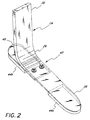
- a pylon member 22 which can be secured to the stump of the amputee (not shown) extends relatively downward therefrom in a generally vertical direction.
- the pylon member 22 for use with the prosthetic foot is of tubular construction, having an equal moment of inertia in all directions to restrict bending in all directions.
- the tubular member 22 is also hollow so that it is relatively light in weight, and utilizes less material, which reduces the cost of production, and preferably has the dimensions of standard tubular pylons.
- Stiffness in the pylon member 22 can also be provided by a stiffer and more dense material.
- the tubular pylon member 22 can also be removed from the prosthetic device, such that the pylon member can be replaced without replacing the prosthetic foot. This permits a broader range of applications.
- the tubular member 22 can be cut and adapted for use by amputees having different stump lengths, including growing amputees.
- the prosthetist merely needs to cut a standard tubular pylon to the appropriate length.
- this eliminates the need to manufacture, as a part of the prosthesis, a long rigid leg section.
- fewer materials are needed, resulting in reduced manufacturing costs.
- a foot portion 24 is secured to the pylon member 22 such that the foot portion extends downward therefrom.
- the foot portion 24 is comprised of an elongated member having a relatively flat, curved surface and a rectilinear cross section made of substantially flexible and durable material.
- the foot portion 24 can be made of non-rectilinear cross-sections to achieve the same benefits discussed herein.
- the foot portion 24 in the preferred embodiment extends generally vertically downward from the pylon member 22, bending about an ankle region 26 and extending to a toe section 28.
- the thickness of the foot portion 24 is a small fraction of its width, whereby the moment of inertia about a horizontal axis perpendicular to the fore and aft direction is substantially smaller than the moment of inertia about a horizontal axis generally in the fore and aft direction.
- This configuration permits bending in a vertical plane in the fore and aft direction, while restricting bending about other planes.
- the configuration also helps to control torsional movement by allowing some, but prohibiting excessive, movement.
- the upper section 30 of the foot portion is, in the preferred embodiment, vertically oriented so that it may be secured to the pylon member 22, as seen in FIGURE 1.
- an attachment device 32 is positioned at the lower end of the pylon member 22, which provides a flat surface upon which the vertical section 30 of the foot portion 24 can be secured.
- the attachment device has one attachment surface 34 which mates with the outside surface of the pylon member 22, and a second attachment surface 36 which mates with the foot portion 24.
- one attachment surface 34 of the attachment device is curved to mate with the outside surface of the tubular pylon member 22, and the second attachment surface 36 is flat to accommodate the flat upper section of the foot portion.
- the attachment device 32 is welded to the pylon member 22 and has two holes (not shown) into which two bolts 38 can be inserted and secured.
- the upper section 30 of the foot portion 24 also has two holes (not shown) which align with the two holes on the attachment device 32, such that by placing and securing two bolts 38 through the foot portion and the attachment device, the foot portion can be secured to the lower end of the pylon member.
- Other methods of securing the pylon member to the foot portion are contemplated, such as those utilizing integrally formed constructions.
- the ankle portion 26 is demountably attached to the pylon 22 by means of fasteners 38 and demountably attached to the heel 40 at the forward connection 42 by means of fasteners 41.
- the ankle portion 26, as well as the heel portion 40 are interchangeable with other similar portions in order to achieve prosthetic adjustability.
- the upper section 30 of the foot portion 24 is vertically aligned so that it extends relatively downward from the attachment device 32 on the pylon member 22. As shown in FIGURE 3, thickness of the foot portion 24 along this vertical section is relatively greater than the thickness of the foot portion along the toe section 28. This thickness provides sufficient rigidity to the connection between the pylon member 22 and the foot portion 24. This upper section 30 is also made relatively thicker to support the vertical load imposed on the prosthetic device 20, as well as restrict undue bending at this juncture. The entire upper vertically aligned section 30 is of uniform thickness and width.
- the foot portion 24 is a substantially constant width from the upper rigid portion 30 down to the toe section 28, with the toe end 46 being rounded to accommodate various cosmesis which simulate an actual foot.
- the foot portion 24 has a width of between 3.8 and 7.6 cm (1.5 and 3 in.), and the width is preferably about 5.1 cm (2 in.).
- the dimensions and parameters may be used, and that the dimensions and parameters provided herein are merely one example of an embodiment.
- a heel portion 40 attached to the foot portion 24 is a heel portion 40, which is secured to the underside of the foot portion 24 between the ankle region 26 and the toe section 28.
- the heel portion 40 is also relatively flat, although it can be curved. It also has a rectilinear cross section in the preferred embodiment, although in other embodiments the cross section does not necessarily have to be rectilinear.
- the heel portion 40 is also made of the same flexible and durable material as the foot portion 24, as will be discussed, and has a thickness which is a small fraction of its width. Thus, its bending characteristics are similar to the bending characteristics of the ankle section.
- the heel portion 40 extends rearward from a forward connection 42 with the foot portion 24, and has a length, in the preferred embodiment, which is greater than its width.
- the configuration of the heel portion 40 is designed to be relatively flexible about an axis parallel to its width, while being resistant to flexing about an axis parallel to its length and about an axis normal to the surface of the heel portion.
- one or two separate sole members 44a and 44b are included in the present invention, as shown in FIGURE 3.
- a front sole member 44a is adhesively attached to the underside of the toe section 28 of the foot portion 24, and a rear sole member 44b is adhered to the underside of the heel portion 40.
- the sole members 44a,b may be constructed from a similar material as the foot and heel portions 24, 40, or may be manufactured from a more pliant material such as urethane or a hardened rubber.
- the present embodiment is made of a resin impregnated, high strength material, such as graphite composite, or a filament structure, arranged in laminates. Excellent results have been obtained using carbon filament with an epoxy binder, such as those disclosed in my previous patents US-A-4,547,913 and US-A-4,822,363.
- the foot portion 24 and heel portions 40 of the present embodiment are made of a resin impregnated, high strength material having substantially elastic flexibility so as to impart relatively low energy absorption to give the wearer high mobility and a relatively natural feel.
- the rigid pylon member 22 can also be made of the same material.
- the pylon member's rigidity is provided predominantly by its tubular shape. But because the material has some elastic flexibility, in spite of the tubular shape, the pylon member 22 has some nominal flexibility.
- the components are not limited to construction from such a material, but rather can be made of materials with such characteristics.
- the present prosthetic foot can also be integrally formed, rather than modularly formed, although in the preferred embodiment, the pylon member 22 is removable from the foot portion 24, and the heel portion 40 is removable from the foot portion. This modularity is provided by a nut-and-bolt construction.
- the foot portion is provided with a tightly curved ankle section 26, curving downward and forward to the toe section 28 which is at approximately a 90° angle with the vertically aligned upper section 30.
- the radius of curvature "r" (shown in FIGURE 3) at this ankle section 26 is, in the preferred embodiment, approximately 5.1 cm (2 in.), with a desirable range being between 1.3 to 7.6 cm (0.5 to 3 in.).
- This tight radius of curvature in conjunction with the relatively stiff pylon member 22 and the relatively thick upper section 30 of the foot portion 24, locates the axis of bending lower to the ground and more closely resembles the position of the human ankle region.
- a lower axis of bending permits the present prosthesis to be mounted on a longer stump, as exhibited by the present trend toward lower amputations.
- this configuration concentrates the flexibility and corresponding bending stresses in the ankle region 26, the present ankle has been designed, as explained below in more detail in connection with Table 1, so as to return good performance characteristics while adequately resisting such bending stresses.
- the foot portion 24 is secured to the back side of the pylon member 22, as can be seen in FIGURE 3.
- This off-center alignment advantageously helps to position the axis of bending closer in line with the center line of any vertical loads imposed on the prosthetic device. This tends to reduce moment forces when the foot is subjected to such vertical loads, and further reduces any horizontal deflection when the toe is subjected to vertical loads, as explained below in more detail.
- This off-center rearward alignment also increases the toe lever arm to provide additional leverage, which assists in providing flex balance.
- the radius of curvature "r" of the ankle section 26 has a center axis which is substantially below the lower end 22a of the pylon member 22, and therefore closer in line with the vertical centerline of the pylon.
- This configuration lowers and isolates the bending of the foot portion 24, while permitting additional flexibility and energy storage and release in the foot portion.
- a longer foot portion tends to be more flexible and therefore provide more energy storage and release.
- the lever arm of the toe section 28 is extended, thereby providing additional toe flexibility and foot portion leverage.
- the foot portion 24 extends downward from the back side of the pylon 22 and extends forward, thereby providing a greater moment arm relative to the bending axis of the ankle section 26. This additional leverage provides the amputee with better control during the toe off phase of a normal stride.
- the foot portion 24 can also be attached to the front side of a pylon member, the lever arm of the toe section 28 would be reduced, thereby permitting less resiliency and energy response in the forward section of the prosthesis.
- the principal design parameters are: (1) the point of attachment of the prosthesis to a relatively rigid upper pylon; (2) the flex characteristics of the ankle member, as determined primarily by its radius of curvature and thickness; (3) the toe length and flex characteristics of the toe member; and (4) the heel length and flex characteristics of the heel member. Other factors, such as overall weight and cosmetic compatibility, must be considered, but these are the more important performance parameters.
- the ankle design also permits an optimal toe and heel configuration to cooperate in the overall performance of the foot prosthesis.
- a prosthesis manufactured in accordance with the present embodiment and having a radius of curvature "r" of about 5.1 cm (2 in.) cooperated with a toe lever arm as measured from the forward point of attachment 42 to the tip of the toe 46 of about 11.4 cm (4.5 in.), while the cooperating heel lever arm from the same point of attachment to the distal tip of the heel 40 is about 11.4 cm (4.5 in.).
- Many other prostheses of different dimensions are to provide for optimization of performance characteristics with safety and low cost.
- the foot portion may be an integral extension of the pylon member, such that the axis of the pylon member is in line with the axis of the upper section 30 of the foot portion.
- some prior devices have a similar configuration, wherein a flexible foot portion extends downward from a rigid upper section, none of the prior devices particularly disclose the tight radius of curvature ankle section 26 and the low bending axis described herein.
- the pylon member 22 has a lower extremity 22a which extends to about 8.9 cm (3.5 in.) from the bottom of the sole members 44a,b. Though this distance "h", as shown in FIG. 3, can be adjusted to accommodate various amputee preferences, including size, weight, resiliency, springiness, flexibility and activity level, the advantages discussed herein are readily obtained if the lower extremity 22a of the pylon member 22 extends no more than about 12.7 cm (5 in.) and no less than about 6.4 cm (2.5 in.) from the bottom of the sole members 44a,b, with a range between 6.4 to 12.7 cm (2.5 to 5 in.).
- the exact location of the pylon member 22 with respect to the foot portion 24 is determined by a combination of factors, including the length, thickness and curvature of the foot portion.
- the present invention is well adapted for use by those who are moderately active and who are willing to sacrifice a small degree of maximum performance in exchange for greater stability and control.
- the prosthetic device 20 achieves a movement and performance that resembles a human limb, it is ideal for active use, such as in running, jogging and jumping.
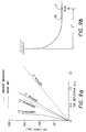
- FIGURES 6 and 7 provide a comparison of the way the prosthesis of the prior art bends with respect to the way the prosthesis of the present embodiment bends.
- the prosthesis of the prior art has a wide range of movement through the length of the flexible prosthetic leg and ankle member. The bending, and therefore deflection, occurs along the entire length of the flexible member.
- the flexible member of the embodiment tends to concentrate bending near the curved ankle section 26, although in a normal gait, additional deflection will occur along the toe section 28.
- FIGURES 6 and 7 are intended to show the deflection of the curved portion of the flexing member, i.e., the ankle section.
- a curved member having a certain radius of curvature deflects both vertically and horizontally when a vertical load is placed at the end of the curved member. For instance, as an upward force is directed at the toe end of the curved member, as schematically shown in FIGURES 8a-c, the toe member will deflect upward, causing a corresponding horizontal deflection in the forward direction ⁇ x. As can be seen in FIGURE 8c, there is both a vertical deflection component and a horizontal deflection component, ⁇ x, which results from an upward force directed at the toe end of the curved member.
- an important aspect of the present invention is the reduction in this horizontal movement or deflection component in the fore and aft direction as the amputee plants the toe.
- the present prosthetic foot reduces this horizontal deflection component, thereby serving to stabilize the amputee and provide a more natural feel.
- a large radius ankle section may be more desirable due to its ability to store additional energy and provide a better energy response.
- a prosthesis having improved control performance may be more desirable.
- the present prosthetic foot provides the amputee with increased control, which will help the amputee build confidence in the prosthetic device, resulting in improved adaptability and recovery.
- FIGURE 8a an experimental ankle loading situation is schematically shown.
- a leg member 50 having an upper substantially vertical section 52, an intermediate curvilinear section 54 and a lower substantially horizontal section 56 is fixed at a point 58 at an upper end.
- An upward force F is applied at the toe end of the leg 50 at point T to simulate a toe push-off of the leg in normal walking or running.
- FIGURE 8b is a force/moment diagram for the curvilinear section 54.
- the upper end will be designated as fixed, as the upper portion 52 is substantially rigid.
- the lower end at point P will experience an upward force F (or a shear force V in FIGURE 8b) and a moment M equaling the force F times the distance L minus r, which is the distance of 56 from the bottom end of the curvilinear section 54 to the application of force F.
- the relative horizontal deflection of the prosthesis caused by a vertically upward force is approximately 0.15 cm (0.058 in.). What this means is that with every step taken, the prosthetic device will move backward a distance of 0.15 cm (0.058 in.) with every 67.9 kg (150 lb m ) load placed on the toe.
- the results of the foregoing examples are also based on ankle sections of constant thickness.
- the tapered ankle section 26 would in fact further decrease the amount of horizontal deflection experienced. This is due to the fact that the more flexible lower portion, as will be discussed, of the ankle section 26 will experience more of the bending as opposed to further up on the ankle section. Thus, as the bending is concentrated lower in the ankle portion by the tapered construction, the horizontal movement will correspondingly decrease.
- the devices were tested under a standard loading machine with the upper end fixedly mounted.
- the load was imposed in an upward direction at point E positioned about 15.2 cm (6 in.) horizontally from the vertical position of the ankle member.
- the upward force F corresponded to a reaction force caused by a load up to and including a 67.9 kg (150 lb m ) placed on the device by an amputee.
- This upward load was connected to a roller to permit horizontal movement at point E as the upward force was applied.
- FIGURE 9a charts the amount of deflection both horizontally and vertically from 0 load to 67.9 kg (150 lb m ) load.
- the results of the experiment were fairly dramatic.
- the amount of vertical and horizontal deflection of the embodiment is shown in the solid lines, and the amount of vertical and horizontal deflection of the prior device is shown in the dashed lines.
- the vertical deflection of the embodiment given a 67.9 kg (150 lb m ) load at point E, was approximately 2.3 cm (0.9 in.), while the amount of horizontal deflection caused by the same load was only approximately 0.5 cm (0.2 in.).
- This difference can also be described in terms of a ratio between the horizontal deflection and the vertical deflection.
- the ratio of horizontal deflection to vertical deflection of the embodiment is a fraction of 0.5/2.3 (.2/.9) or .22.
- the ratio of horizontal deflection to vertical deflection experienced by the prior device is a fraction of 1.9/4.3 (.75/1.7), which is approximately .44. This ratio is significant when considering that with every step taken, the vertical deflection of the toe section will result in a corresponding rearward horizontal deflection amounting to some fraction of the vertical deflection.
- the prosthetic device Given a .44 ratio, the prosthetic device will move backward horizontally approximately 1.1 cm (.44 in.) with every cm (inch) of vertical deflection experienced. Conversely, in the embodiment, the amount of horizontal rearward deflection will be only approximately 0.56 cm (.22 in.) with every cm (inch) of vertical deflection experienced.
- the ratio of horizontal deflection to vertical deflection at point P will be nearly a constant ratio of approximately .59. Of course, this depends on whether the curve follows a single radius arc, and whether the curve extends along a 90° angle of radius in radians. What causes the ratio of horizontal deflection to vertical deflection to decrease is a function of how tight the radius of curvature of the ankle section is and how long the toe section 56 extends forward from the ankle section.
- the horizontal toe section 56 will experience little or no horizontal deflection as vertical deflection increases, a longer toe section 56 will allow additional vertical deflection without increasing horizontal deflection.
- a longer toe section 56 can be extended from the bottom of the ankle section, resulting in the capacity to permit additional vertical deflection without increasing associated horizontal deflection. This phenomenon significantly decreases the ratio between the horizontal deflection and vertical deflection as loads increase.
- the horizontal deflection ⁇ X is no more than 0.64 cm (0.25 in.), given a 67.9 kg (150 lb m ) load at point E, although up to 1.3 cm (0.5 in.) would be permissible.
- the ratio of horizontal deflection to vertical deflection at point E (or T) according to the invention is less than one-third. As discussed, this ratio is nearly constant (.59) at point P, see FIGURE 8a, whether the ankle section radius is large or small.
- the ratio at point T varies depending on how small the radius is and how long the toe section 56 is. With a small radius ankle section, the resultant toe section 56 will be longer, resulting in greater vertical deflection at point T without necessarily increasing horizontal deflection.
- the ratio will also vary depending on whether the thickness is tapered along the ankle and toe sections. The thinner the toe section 56, the greater the vertical deflection at point T will be, and consequently, the greater the energy storage will be, without increasing horizontal deflection along the ankle section.
- the foot portion 24 has a tapered thickness, the taper being a function of the flexibility in the foot portion.
- the upper vertical section 30 is substantially uniform in thickness
- the ankle section 26 has a thickness which is tapered from the upper part "a” through the middle part "b” to the lower part "c" of the curved section.
- a series of standard thicknesses are provided for amputees of varying sizes.
- the prosthetic foot of the present invention may be provided in nine sizes with the designation "A1” through “A9,” “A1” being the thinnest for the smallest amputee and “A9” being the thickest for a larger amputee.
- Table 1 gives thicknesses "t” at points “a,” “b” and “c,” corresponding to the upper, middle and lower portions of the ankle portion 26 for the nine size categories.
- Table 1 provides the area moment of inertia "I" about the bending axis for the points "a,” “b” and “c” based on a foot portion 24 width of 5.1 cm (2 in.) Tapered Ankle Section Thickness and Moment of Inertia t a cm t b cm t c cm I a cm 4 I b cm 4 100(Ib/ 1a ) I c cm 4 100(Ic/ 1a ) A1 .787 .635 .551 .208 .108 52.0 .0708 34.0 A2 .815 .663 .574 .229 .123 53.7 .0799 34.8 A3 .848 .683 .592 .258 .135 52.2 .0878 34.0 A4 .881 .706 .612 .290 .149 51.4 .0970 33.4 A5 .927 .742 .643 .337 .173
- the thickness at the lower point "c" of the ankle section 26 is approximately 70% of the thickness at the upper part "a" for the sizes "A1" through “A9.” Due to the area moment of inertia being proportional to the cube of the thickness at any one point, however, the area moment of inertia of I c in the lower region of the ankle 26 is between 31% and 35% of the area moment of inertia I a .
- the area moment of inertia I b at the middle section is between 48% and 54% of the area moment of inertia I a at the upper region "a.” Due to the fact that the amount of deflection from a particular applied force is inversely proportional to the area moment of inertia, a majority of the deflection from bending of the prosthetic device 20 will occur in the lower portion of the ankle section 26, and more particularly, below the middle region "b" of the ankle section.
- the stiffer upper part "a" of the curved section 26 also imparts a slightly greater resistance to bending, extending somewhat downwardly the stiffness of the pylon member 22 and the vertically aligned upper section 30.
- the flex characteristics of the toe and heel sections of a prosthetic foot are also important parameters in determining its overall performance.
- their thickness or taper will also affect their flex characteristics.
- additional flexibility can be imparted to the toe end 46 of the prosthesis.
- the toe end 46 has a thickness which is approximately one-third to one-half of the thickness of the vertically aligned upper section 30 of the foot portion 24.
- the heel portion 40 is also made relatively thinner than the vertically aligned upper section 30 of the foot portion 24, so as to impart flexibility to the heel area.
- a taper can also be provided in the heel portion 40, wherein the front end 40a of the heel portion which is connected to the underside of the foot portion 24 is slightly thicker than the rearward end 40b of the heel portion.
- each of these members are tapered, as shown in FIGURE 1, many of the advantages of the present invention can be obtained utilizing a number of varying thicknesses, including a constant thickness throughout the foot portion 24 and heel portion 40. However, tapering of these members provides additional "feel" to the foot prosthesis 20, which would otherwise be absent without such tapering.
- the toe section 28 and heel portion 40 are thinner, and thus are relatively more flexible than the ankle section 26 and the vertically aligned upper section 30. This flexibility is provided to more closely resemble the flexibility of movement found in the human foot.
- a number of joints are located which allow the foot to move in various directions. For instance, the metatarsal is joined such that the front end of the foot can move with respect to the remainder of the foot.
- the front end of the foot prosthesis thinner, additional flexibility is imparted so as to more closely resemble the flexibility of the human foot.
- the width of the foot portion 24 can also vary, although in the preferred embodiment, the width is uniformly approximately 5.1 cm (2 in.).
- the foot portion 24 and heel portion 40 can also be tapered in width, as well as thickness, to provide additional resistance or flexibility about various axes. For instance, by making the foot portion 24 slightly less wide along the vertically extending upper section 30, additional torsional flexibility can be provided.
- the foot prosthesis 20 performs quite adequately and mimics the movement of a natural human limb.
- the design of the present invention simulates ankle motion that is smooth and continuous from heel-strike to toe-off.
- the load exerted on the prosthetic device depresses the heel 40, which acts as a lever to plantarflex the toe 28.
- the ankle section 26 bends backward, opening its radius of curvature. The natural tendency of the heel portion 40 and ankle section 26 to return to original flex positions helps shift the weight of the amputee forward to midstance.
- the prosthesis 20 dorsiflexes, bending the ankle section 26 forward, causing the radius of curvature to close relative to the 90° position.
- the amputee's weight is shifted forward, causing the toe section 28 to bend.
- the prosthesis assumes a forwardly angled position, from which the natural tendency of the ankle section 26 to return to its original position causes the amputee to move forward as the energy is released at toe-off.
- the present invention provides a unique combination of prosthetic elements which perform much like a normal ankle joint. When used with a leg and shin portion which is relatively stiff, most of the bending takes place in a low, confined ankle region and a flexible toe and heel section.
- the present invention provides improved control and stability not previously provided by prior devices, as it reduces excessive horizontal movement and confines bending in a tight ankle section.
Landscapes
- Health & Medical Sciences (AREA)
- Transplantation (AREA)
- Engineering & Computer Science (AREA)
- Vascular Medicine (AREA)
- Oral & Maxillofacial Surgery (AREA)
- Cardiology (AREA)
- Biomedical Technology (AREA)
- Heart & Thoracic Surgery (AREA)
- Life Sciences & Earth Sciences (AREA)
- Animal Behavior & Ethology (AREA)
- General Health & Medical Sciences (AREA)
- Public Health (AREA)
- Veterinary Medicine (AREA)
- Orthopedic Medicine & Surgery (AREA)
- Manufacturing & Machinery (AREA)
- Prostheses (AREA)
Abstract
Description
- ΔX
- - Movement in the horizontal direction of the Point P in FIGURES 8b and 8c
- E
- - Modulus of Elasticity
- I
- - Moment of Inertia
- M
- - Applied Moment
- V
- - Vertical Shear Load
- R
- - Radius
-
- - Included Angle of Radius in Radians
- ΔX1
- = 0.15 cm (0.058 in.)
- ΔX2
- = 0.87 cm (0.343 in.)
| Tapered Ankle Section Thickness and Moment of Inertia | ||||||||
| ta cm | tb cm | tc cm | Ia cm4 | Ib cm4 | 100(Ib/1a) | Ic cm4 | 100(Ic/1a) | |
| A1 | .787 | .635 | .551 | .208 | .108 | 52.0 | .0708 | 34.0 |
| A2 | .815 | .663 | .574 | .229 | .123 | 53.7 | .0799 | 34.8 |
| A3 | .848 | .683 | .592 | .258 | .135 | 52.2 | .0878 | 34.0 |
| A4 | .881 | .706 | .612 | .290 | .149 | 51.4 | .0970 | 33.4 |
| A5 | .927 | .742 | .643 | .337 | .173 | 51.2 | .112 | 33.3 |
| A6 | .980 | .780 | .676 | .399 | .201 | 50.3 | .131 | 32.7 |
| A7 | 1.03 | .818 | .706 | .466 | .231 | 49.6 | .149 | 32.0 |
| A8 | 1.09 | .859 | .742 | .545 | .268 | 49.2 | .173 | 31.7 |
| A9 | 1.14 | .890 | .775 | .629 | .305 | 48.5 | .197 | 31.3 |
Claims (9)
- A prosthetic foot for providing resilient kinematic support to an amputee relative to a ground surface, comprising:a foot portion (24) including an upper section (30) configured to be securable to a pylon (22), a resilient curved ankle section (26) extending downwardly and forwardly from said upper section (30), and a toe section (28) formed integrally with and extending forwardly and substantially horizontally from said ankle section (26); anda heel section (40) extending rearwardly from said ankle section (26);
characterized in thatsaid ankle section (26) has a defined radius of curvature (r) of between 1.3 cm and 7.6 cm (0.5 in and 3.0 in) about a bending axis located at or about the location of a normal human ankle joint;said foot portion (24) is configured such that as a vertically upwardly directed force (F) is placed at the tip of said toe section (28), the resultant horizontal deflection of the tip in the direction of said toe section (28) is less than one-third of the resultant upward deflection of the tip of said toe section (28). - The prosthetic foot of Claim 1, wherein said radius of curvature (r) of said ankle section (26) is about 5.1 cm (2.0 in).
- The prosthetic foot of Claim 1 or 2, wherein said pylon (22) has a lower extremity (22a) which terminates between 6.4 cm and 12.7 cm (2.5 in and 5.0 in) above the bottom of said toe section (28).
- The prosthetic foot of Claim 1, 2 or 3, wherein said foot portion (24) is tapered from said ankle section (26) to said toe section (28) wherein substantially uniform stress distribution is obtained.
- The prosthetic foot of Claim 4, wherein the thickness of said toe section (28) is between about one-third to one-half the thickness of said ankle section (26).
- The prosthetic foot of any one of Claims 1 to 5, wherein said toe section (28) and said heel section (40) are substantially flat and co-planar or parallel with respect to one another.
- The prosthetic foot of Claim 6, wherein said heel section (40) is configured to be selectively attached and detached at a point between said ankle section (26 and said toe section (28).
- The prosthetic foot of any one of the Claims 1 to 7, wherein said upper section (30) is configured to be attached to a cylindrical pylon (22) using an attachment member (32) having a substantially flat surface on one side adapted to mate with said upper section (30) and a substantially concave cylindrical surface on the opposite side adapted to mate with said cylindrical pylon (22).
- The prosthetic foot of Claim 8, wherein said attachment member (32) is secured between a front side of said upper section (30) relative to a forward direction of said amputee, and a rear side of said cylindrical pylon (22).
Applications Claiming Priority (3)
| Application Number | Priority Date | Filing Date | Title |
|---|---|---|---|
| US43150 | 1993-03-31 | ||
| US08/043,150 US5824112A (en) | 1989-04-13 | 1993-03-31 | Prosthetic device incorporating low ankle design |
| PCT/US1994/001578 WO1994022398A1 (en) | 1993-03-31 | 1994-02-15 | Prosthetic device incorporating low ankle design |
Publications (2)
| Publication Number | Publication Date |
|---|---|
| EP0691833A1 EP0691833A1 (en) | 1996-01-17 |
| EP0691833B1 true EP0691833B1 (en) | 1998-07-08 |
Family
ID=21925752
Family Applications (1)
| Application Number | Title | Priority Date | Filing Date |
|---|---|---|---|
| EP94911384A Expired - Lifetime EP0691833B1 (en) | 1993-03-31 | 1994-02-15 | Prosthetic device incorporating low ankle design |
Country Status (14)
| Country | Link |
|---|---|
| US (2) | US5824112A (en) |
| EP (1) | EP0691833B1 (en) |
| JP (1) | JP3015920B2 (en) |
| KR (1) | KR0176289B1 (en) |
| AT (1) | ATE168001T1 (en) |
| AU (1) | AU682856B2 (en) |
| BR (1) | BR9405955A (en) |
| CA (1) | CA2158015C (en) |
| DE (1) | DE69411552T2 (en) |
| DK (1) | DK0691833T3 (en) |
| ES (1) | ES2120612T3 (en) |
| FI (1) | FI114851B (en) |
| TW (1) | TW267940B (en) |
| WO (1) | WO1994022398A1 (en) |
Families Citing this family (53)
| Publication number | Priority date | Publication date | Assignee | Title |
|---|---|---|---|---|
| TW267940B (en) * | 1993-03-31 | 1996-01-11 | Phillips L Van | |
| GB9621137D0 (en) * | 1996-10-10 | 1996-11-27 | Chas A Blatchford And Sons Lim | An above-knee lower limb prosthesis and a shin component for the prosthesis |
| GB9621138D0 (en) * | 1996-10-10 | 1996-11-27 | Chas A Blatchford And Sons Lim | A below-knee lower limb prosthesis and a shin component for the prosthesis |
| KR100362736B1 (en) * | 2000-04-03 | 2002-12-28 | 한국과학기술원 | Energy-storing prosthetic feet |
| US7044984B2 (en) * | 2000-04-26 | 2006-05-16 | Rehabilitation Institute Of Chicago | High profile multiaxial prosthetic foot |
| US7686848B2 (en) | 2000-06-30 | 2010-03-30 | Freedom Innovations, Llc | Prosthetic foot with energy transfer |
| US7341603B2 (en) * | 2000-06-30 | 2008-03-11 | Applied Composite Technology, Inc. | Prosthetic foot with energy transfer including variable orifice |
| WO2002002034A1 (en) * | 2000-06-30 | 2002-01-10 | Roland J. Christensen, As Operating Manager Of Rjc Development, Lc, General Partner Of The Roland J. Christensen Family Limited Partnership | Prosthetic foot |
| US20050216098A1 (en) * | 2000-06-30 | 2005-09-29 | Roland J. Christensen | Variable resistance cell |
| US20060241783A1 (en) * | 2000-06-30 | 2006-10-26 | Christensen Roland J | Variable resistance cell |
| US7572299B2 (en) * | 2000-06-30 | 2009-08-11 | Freedom Innovations, Llc | Prosthetic foot with energy transfer |
| US6875241B2 (en) | 2000-06-30 | 2005-04-05 | Roland J. Christensen, As Operating Manager Of Rjc Development Lc, General Partner Of The Roland J. Christensen Family Limited Partnership | Variable resistance cell |
| US6443995B1 (en) | 2000-12-22 | 2002-09-03 | Barry W. Townsend | Prosthetic foot |
| US7410503B2 (en) * | 2001-03-30 | 2008-08-12 | Bioquest Prosthetics Llc | Prosthetic foot with tunable performance |
| US7611543B2 (en) * | 2001-03-30 | 2009-11-03 | Bioquest Prosthetics, Llc | Prosthetic foot with tunable performance |
| US6562075B2 (en) | 2001-03-30 | 2003-05-13 | Barry W. Townsend | Prosthetic foot with tunable performance |
| US7429272B2 (en) * | 2001-03-30 | 2008-09-30 | Bioquest Prosthetics Llc | Prosthetic foot with tunable performance |
| US8070829B2 (en) * | 2003-09-30 | 2011-12-06 | Bioquest Prosthetics Llc | Prosthetic foot with tunable performance |
| US20070213841A1 (en) * | 2001-03-30 | 2007-09-13 | Townsend Barry W | Prosthetic foot with tunable performance |
| US7507259B2 (en) * | 2001-03-30 | 2009-03-24 | Bioquest Prosthetics, Llc | Prosthetic foot with tunable performance |
| US8236062B2 (en) | 2001-03-30 | 2012-08-07 | Bioquest Prosthetics Llc | Prosthetic foot with tunable performance |
| US7374578B2 (en) | 2001-03-30 | 2008-05-20 | Bioquest Prosthetics, Llc | Prosthetic foot with tunable performance |
| US7578852B2 (en) | 2001-03-30 | 2009-08-25 | Bioquest Prosthetics, Llc | Prosthetic foot with tunable performance and improved vertical load/shock absorption |
| US6793683B1 (en) * | 2002-08-22 | 2004-09-21 | Aldo A. Laghi | Prosthetic foot with medial/lateral stabilization |
| US6702859B1 (en) * | 2002-08-22 | 2004-03-09 | Aldo A. Laghi | Dynamic prosthetic foot with multiple load points and anterior/posterior upper sections |
| US7419509B2 (en) * | 2002-10-08 | 2008-09-02 | Freedom Innovations, Llc | Prosthetic foot with a resilient ankle |
| US6911052B2 (en) | 2002-10-08 | 2005-06-28 | Roland J. Christensen, As Operating Manager Of Rjc Development, Lc, General Partner Of The Roland J. Christensen Family Limited Partnership | Prosthetic foot with oblique attachment |
| US6805717B2 (en) | 2002-10-08 | 2004-10-19 | Roland J. Christensen, As Operating Manager Of Rjc Development, Lc, General Manager Of The Roland J. Christensen Family Limited Partnership | Energy-storing prosthetic foot with elongated forefoot |
| US6929665B2 (en) * | 2002-10-08 | 2005-08-16 | Roland J. Christensen | Prosthetic foot with a resilient ankle |
| US8574314B2 (en) | 2003-09-30 | 2013-11-05 | Bioquest Prosthetics Llc | Resilient prosthetic and orthotic components which incorporate a plurality of sagittally oriented struts |
| US7520904B2 (en) | 2003-10-21 | 2009-04-21 | Freedom Innovations, Llc | Prosthetic foot with an adjustable ankle and method |
| US6966933B2 (en) * | 2003-10-21 | 2005-11-22 | Roland J. Christensen, As Operating Manager Of Rjc Development, Lc, General Partner Of The Roland J. Christensen Family Limited Partnership | Prosthetic foot with an adjustable ankle and method |
| US7172630B2 (en) * | 2004-02-20 | 2007-02-06 | Roland J. Christensen, As Operating Manager Of Rjc Development, Lc, General Partner Of The Roland J. Christensen Family Limited Partnership | Prosthetic foot with cam |
| CA2561320A1 (en) * | 2004-04-01 | 2005-10-20 | Barry W. Townsend | Prosthetic foot with tunable performance |
| US7347877B2 (en) | 2004-05-28 | 2008-03-25 | össur hf | Foot prosthesis with resilient multi-axial ankle |
| US20050288792A1 (en) * | 2004-06-23 | 2005-12-29 | Landes Mark D | Modular ankle prosthesis and associated method |
| US7618464B2 (en) * | 2006-08-03 | 2009-11-17 | Freedom Innovations, Llc | Prosthetic foot with variable medial/lateral stiffness |
| US7824446B2 (en) | 2006-12-06 | 2010-11-02 | Freedom Innovations, Llc | Prosthetic foot with longer upper forefoot and shorter lower forefoot |
| US7727285B2 (en) | 2007-01-30 | 2010-06-01 | Freedom Innovations, Llc | Prosthetic foot with variable medial/lateral stiffness |
| US20080228288A1 (en) * | 2007-03-13 | 2008-09-18 | Ronald Harry Nelson | Composite Prosthetic Foot |
| US7794506B2 (en) | 2007-09-18 | 2010-09-14 | Freedom Innovations, Llc | Multi-axial prosthetic ankle |
| US8034121B2 (en) | 2008-04-18 | 2011-10-11 | Freedom Innovations, Llc | Prosthetic foot with two leaf-springs joined at heel and toe |
| EP2538891B1 (en) | 2010-02-26 | 2015-04-15 | Össur HF | Prosthetic foot with a curved split |
| US8500825B2 (en) | 2010-06-29 | 2013-08-06 | Freedom Innovations, Llc | Prosthetic foot with floating forefoot keel |
| US20130024008A1 (en) * | 2011-07-22 | 2013-01-24 | Treger Elisabeth A | Shoe for prosthetic feet |
| US8961618B2 (en) | 2011-12-29 | 2015-02-24 | össur hf | Prosthetic foot with resilient heel |
| EP2996640A1 (en) * | 2013-05-14 | 2016-03-23 | University of Washington through its Center for Commercialization | Medial-lateral stabilizing ankle/foot for angled and rough ground gait |
| US9999524B2 (en) | 2014-06-30 | 2018-06-19 | össur hf | Prosthetic feet and foot covers |
| USD795433S1 (en) | 2015-06-30 | 2017-08-22 | Össur Iceland Ehf | Prosthetic foot cover |
| WO2018218139A1 (en) * | 2017-05-26 | 2018-11-29 | Massachusetts Institute Of Technology | Method for design and manufacture of compliant prosthetic foot |
| USD915596S1 (en) | 2018-04-10 | 2021-04-06 | Össur Iceland Ehf | Prosthetic foot with tapered fasteners |
| US11607325B2 (en) | 2019-06-03 | 2023-03-21 | Massachusetts Institute Of Technology | Shape optimization for prosthetic feet |
| US12201537B2 (en) | 2020-11-30 | 2025-01-21 | Össur Iceland Ehf | Prosthetic foot with layers of fibrous material |
Family Cites Families (20)
| Publication number | Priority date | Publication date | Assignee | Title |
|---|---|---|---|---|
| US61780A (en) * | 1867-02-05 | Alexander t | ||
| DE325171C (en) * | 1919-08-19 | 1920-09-10 | Julius Fuchs Dr | Artificial foot |
| DE963849C (en) * | 1954-02-04 | 1957-05-16 | Hermann Steiner | Double wire insert for doll limbs |
| SU806023A1 (en) * | 1977-04-21 | 1981-02-23 | Ленинградский Научно-Исследовательскийинститут Протезирования | Artificial foot |
| SU778732A1 (en) * | 1977-08-30 | 1980-12-05 | Центральный Ордена Трудового Красного Знамени Научно-Исследовательский Институт Протезирования И Протезостроения | Artificial foot |
| US4547913A (en) * | 1983-07-11 | 1985-10-22 | Flex Foot, Inc. | Composite prosthetic foot and leg |
| US4645509A (en) * | 1984-06-11 | 1987-02-24 | Model & Instrument Development Corporation | Prosthetic foot having a cantilever spring keel |
| US4822363A (en) * | 1985-08-01 | 1989-04-18 | Phillips L Van | Modular composite prosthetic foot and leg |
| US5181932A (en) * | 1989-04-13 | 1993-01-26 | Phillips L Van | Foot prosthesis having auxiliary ankle construction |
| FR2626463B1 (en) * | 1988-01-28 | 1992-06-19 | Espace Composites Sarl | REINFORCEMENT DEVICE FOR PROSTHETIC FOOT |
| US4959073A (en) * | 1988-06-06 | 1990-09-25 | John Merlette | Foot prosthesis and method of making same |
| US5037444A (en) * | 1989-01-05 | 1991-08-06 | Phillips L Van | Prosthetic foot |
| US4938776A (en) * | 1989-05-12 | 1990-07-03 | Masinter Robert A | Integrated ankle and foot prosthetic system |
| DE3918810A1 (en) * | 1989-06-09 | 1990-12-13 | Bock Orthopaed Ind | JOINTLESS PROSTHESIC FOOT |
| US4994086A (en) * | 1989-08-09 | 1991-02-19 | United States Manufacturing Company | Universal modular frame for above-knee endoskeletal prosthesis |
| DE4038063C2 (en) * | 1990-11-29 | 1995-04-20 | Bock Orthopaed Ind | Articulated prosthetic foot |
| US5181933A (en) * | 1991-02-28 | 1993-01-26 | Phillips L Van | Split foot prosthesis |
| AU2580092A (en) * | 1991-09-06 | 1993-04-05 | Van L. Phillips | Low-profile symes foot prosthesis |
| US5156631A (en) * | 1991-09-16 | 1992-10-20 | John Merlette | Foot and leg prosthesis and method of making same |
| TW267940B (en) * | 1993-03-31 | 1996-01-11 | Phillips L Van |
-
1993
- 1993-03-30 TW TW082102356A patent/TW267940B/zh active
- 1993-03-31 US US08/043,150 patent/US5824112A/en not_active Expired - Lifetime
-
1994
- 1994-02-15 EP EP94911384A patent/EP0691833B1/en not_active Expired - Lifetime
- 1994-02-15 AU AU63921/94A patent/AU682856B2/en not_active Ceased
- 1994-02-15 BR BR9405955A patent/BR9405955A/en not_active IP Right Cessation
- 1994-02-15 AT AT94911384T patent/ATE168001T1/en not_active IP Right Cessation
- 1994-02-15 DK DK94911384T patent/DK0691833T3/en active
- 1994-02-15 ES ES94911384T patent/ES2120612T3/en not_active Expired - Lifetime
- 1994-02-15 JP JP6522048A patent/JP3015920B2/en not_active Expired - Fee Related
- 1994-02-15 DE DE69411552T patent/DE69411552T2/en not_active Expired - Lifetime
- 1994-02-15 CA CA002158015A patent/CA2158015C/en not_active Expired - Fee Related
- 1994-02-15 KR KR1019950703892A patent/KR0176289B1/en not_active IP Right Cessation
- 1994-02-15 WO PCT/US1994/001578 patent/WO1994022398A1/en active IP Right Grant
-
1995
- 1995-09-27 FI FI954588A patent/FI114851B/en active IP Right Grant
-
1998
- 1998-04-14 US US09/060,019 patent/US6254643B1/en not_active Expired - Fee Related
Also Published As
| Publication number | Publication date |
|---|---|
| KR960700666A (en) | 1996-02-24 |
| FI954588A (en) | 1995-10-09 |
| EP0691833A1 (en) | 1996-01-17 |
| BR9405955A (en) | 1995-12-12 |
| US5824112A (en) | 1998-10-20 |
| JPH08508420A (en) | 1996-09-10 |
| CA2158015C (en) | 1999-10-26 |
| ATE168001T1 (en) | 1998-07-15 |
| DE69411552T2 (en) | 1999-01-07 |
| JP3015920B2 (en) | 2000-03-06 |
| FI114851B (en) | 2005-01-14 |
| AU682856B2 (en) | 1997-10-23 |
| CA2158015A1 (en) | 1994-10-13 |
| DK0691833T3 (en) | 1999-04-19 |
| FI954588A0 (en) | 1995-09-27 |
| US6254643B1 (en) | 2001-07-03 |
| AU6392194A (en) | 1994-10-24 |
| TW267940B (en) | 1996-01-11 |
| DE69411552D1 (en) | 1998-08-13 |
| ES2120612T3 (en) | 1998-11-01 |
| WO1994022398A1 (en) | 1994-10-13 |
| KR0176289B1 (en) | 1999-04-01 |
Similar Documents
| Publication | Publication Date | Title |
|---|---|---|
| EP0691833B1 (en) | Prosthetic device incorporating low ankle design | |
| CA2520808C (en) | Prosthetic foot with tunable performance and improved vertical load/shock absorption | |
| US6482236B2 (en) | Prosthetic ankle joint mechanism | |
| US6969408B2 (en) | Low profile active shock module prosthesis | |
| EP2522311B1 (en) | Prosthetic foot | |
| US7578852B2 (en) | Prosthetic foot with tunable performance and improved vertical load/shock absorption | |
| AU743488B2 (en) | Foot prosthesis having cushioned ankle | |
| US5976191A (en) | Foot prosthesis having curved forefoot | |
| US4822363A (en) | Modular composite prosthetic foot and leg | |
| US8808395B2 (en) | Resilient prosthetic and orthotic components which incorporate a plurality of sagittally oriented struts | |
| CN1972650A (en) | Adjustable prosthetic feet | |
| WO1996023461A1 (en) | Prosthetic foot | |
| CA2561314C (en) | Prosthetic foot with tunable performance | |
| US8236062B2 (en) | Prosthetic foot with tunable performance | |
| Esquenazi et al. | Prosthetic feet and ankle mechanisms |
Legal Events
| Date | Code | Title | Description |
|---|---|---|---|
| PUAI | Public reference made under article 153(3) epc to a published international application that has entered the european phase |
Free format text: ORIGINAL CODE: 0009012 |
|
| 17P | Request for examination filed |
Effective date: 19950901 |
|
| AK | Designated contracting states |
Kind code of ref document: A1 Designated state(s): AT BE CH DE DK ES FR GB GR IE IT LI LU MC NL PT SE |
|
| 17Q | First examination report despatched |
Effective date: 19960607 |
|
| GRAG | Despatch of communication of intention to grant |
Free format text: ORIGINAL CODE: EPIDOS AGRA |
|
| RBV | Designated contracting states (corrected) |
Designated state(s): AT BE CH DE DK ES FR GB GR IE IT LI LU MC NL PT SE |
|
| GRAG | Despatch of communication of intention to grant |
Free format text: ORIGINAL CODE: EPIDOS AGRA |
|
| GRAH | Despatch of communication of intention to grant a patent |
Free format text: ORIGINAL CODE: EPIDOS IGRA |
|
| GRAH | Despatch of communication of intention to grant a patent |
Free format text: ORIGINAL CODE: EPIDOS IGRA |
|
| GRAA | (expected) grant |
Free format text: ORIGINAL CODE: 0009210 |
|
| AK | Designated contracting states |
Kind code of ref document: B1 Designated state(s): AT BE CH DE DK ES FR GB GR IE IT LI LU MC NL PT SE |
|
| REF | Corresponds to: |
Ref document number: 168001 Country of ref document: AT Date of ref document: 19980715 Kind code of ref document: T |
|
| REG | Reference to a national code |
Ref country code: CH Ref legal event code: EP |
|
| REF | Corresponds to: |
Ref document number: 69411552 Country of ref document: DE Date of ref document: 19980813 |
|
| ET | Fr: translation filed | ||
| REG | Reference to a national code |
Ref country code: IE Ref legal event code: FG4D |
|
| REG | Reference to a national code |
Ref country code: CH Ref legal event code: NV Representative=s name: TROESCH SCHEIDEGGER WERNER AG |
|
| REG | Reference to a national code |
Ref country code: ES Ref legal event code: FG2A Ref document number: 2120612 Country of ref document: ES Kind code of ref document: T3 |
|
| REG | Reference to a national code |
Ref country code: PT Ref legal event code: SC4A Free format text: AVAILABILITY OF NATIONAL TRANSLATION Effective date: 19981007 |
|
| REG | Reference to a national code |
Ref country code: DK Ref legal event code: T3 |
|
| PLBE | No opposition filed within time limit |
Free format text: ORIGINAL CODE: 0009261 |
|
| STAA | Information on the status of an ep patent application or granted ep patent |
Free format text: STATUS: NO OPPOSITION FILED WITHIN TIME LIMIT |
|
| 26N | No opposition filed | ||
| PGFP | Annual fee paid to national office [announced via postgrant information from national office to epo] |
Ref country code: GR Payment date: 20010222 Year of fee payment: 8 Ref country code: ES Payment date: 20010222 Year of fee payment: 8 |
|
| PGFP | Annual fee paid to national office [announced via postgrant information from national office to epo] |
Ref country code: AT Payment date: 20010223 Year of fee payment: 8 |
|
| PGFP | Annual fee paid to national office [announced via postgrant information from national office to epo] |
Ref country code: LU Payment date: 20010322 Year of fee payment: 8 |
|
| PGFP | Annual fee paid to national office [announced via postgrant information from national office to epo] |
Ref country code: PT Payment date: 20010502 Year of fee payment: 8 |
|
| PGFP | Annual fee paid to national office [announced via postgrant information from national office to epo] |
Ref country code: MC Payment date: 20010514 Year of fee payment: 8 |
|
| REG | Reference to a national code |
Ref country code: GB Ref legal event code: IF02 |
|
| PG25 | Lapsed in a contracting state [announced via postgrant information from national office to epo] |
Ref country code: LU Free format text: LAPSE BECAUSE OF NON-PAYMENT OF DUE FEES Effective date: 20020215 Ref country code: AT Free format text: LAPSE BECAUSE OF NON-PAYMENT OF DUE FEES Effective date: 20020215 |
|
| PG25 | Lapsed in a contracting state [announced via postgrant information from national office to epo] |
Ref country code: ES Free format text: LAPSE BECAUSE OF NON-PAYMENT OF DUE FEES Effective date: 20020216 |
|
| PG25 | Lapsed in a contracting state [announced via postgrant information from national office to epo] |
Ref country code: PT Free format text: LAPSE BECAUSE OF NON-PAYMENT OF DUE FEES Effective date: 20020831 |
|
| PG25 | Lapsed in a contracting state [announced via postgrant information from national office to epo] |
Ref country code: MC Free format text: LAPSE BECAUSE OF NON-PAYMENT OF DUE FEES Effective date: 20020901 |
|
| PG25 | Lapsed in a contracting state [announced via postgrant information from national office to epo] |
Ref country code: GR Free format text: LAPSE BECAUSE OF NON-PAYMENT OF DUE FEES Effective date: 20020909 |
|
| REG | Reference to a national code |
Ref country code: PT Ref legal event code: MM4A Free format text: LAPSE DUE TO NON-PAYMENT OF FEES Effective date: 20020831 |
|
| REG | Reference to a national code |
Ref country code: ES Ref legal event code: FD2A Effective date: 20030922 |
|
| PGFP | Annual fee paid to national office [announced via postgrant information from national office to epo] |
Ref country code: NL Payment date: 20060205 Year of fee payment: 13 |
|
| PGFP | Annual fee paid to national office [announced via postgrant information from national office to epo] |
Ref country code: IE Payment date: 20060213 Year of fee payment: 13 |
|
| PGFP | Annual fee paid to national office [announced via postgrant information from national office to epo] |
Ref country code: GB Payment date: 20060215 Year of fee payment: 13 Ref country code: DK Payment date: 20060215 Year of fee payment: 13 Ref country code: CH Payment date: 20060215 Year of fee payment: 13 |
|
| PGFP | Annual fee paid to national office [announced via postgrant information from national office to epo] |
Ref country code: FR Payment date: 20060220 Year of fee payment: 13 |
|
| PGFP | Annual fee paid to national office [announced via postgrant information from national office to epo] |
Ref country code: IT Payment date: 20060228 Year of fee payment: 13 |
|
| PGFP | Annual fee paid to national office [announced via postgrant information from national office to epo] |
Ref country code: BE Payment date: 20060410 Year of fee payment: 13 |
|
| PG25 | Lapsed in a contracting state [announced via postgrant information from national office to epo] |
Ref country code: LI Free format text: LAPSE BECAUSE OF NON-PAYMENT OF DUE FEES Effective date: 20070228 Ref country code: CH Free format text: LAPSE BECAUSE OF NON-PAYMENT OF DUE FEES Effective date: 20070228 |
|
| REG | Reference to a national code |
Ref country code: CH Ref legal event code: PL Ref country code: DK Ref legal event code: EBP |
|
| GBPC | Gb: european patent ceased through non-payment of renewal fee |
Effective date: 20070215 |
|
| NLV4 | Nl: lapsed or anulled due to non-payment of the annual fee |
Effective date: 20070901 |
|
| REG | Reference to a national code |
Ref country code: IE Ref legal event code: MM4A |
|
| REG | Reference to a national code |
Ref country code: FR Ref legal event code: ST Effective date: 20071030 |
|
| BERE | Be: lapsed |
Owner name: *PHILLIPS VAN L. Effective date: 20070228 |
|
| PG25 | Lapsed in a contracting state [announced via postgrant information from national office to epo] |
Ref country code: BE Free format text: LAPSE BECAUSE OF NON-PAYMENT OF DUE FEES Effective date: 20070228 |
|
| PG25 | Lapsed in a contracting state [announced via postgrant information from national office to epo] |
Ref country code: NL Free format text: LAPSE BECAUSE OF NON-PAYMENT OF DUE FEES Effective date: 20070901 Ref country code: IE Free format text: LAPSE BECAUSE OF NON-PAYMENT OF DUE FEES Effective date: 20070215 Ref country code: DK Free format text: LAPSE BECAUSE OF NON-PAYMENT OF DUE FEES Effective date: 20070228 |
|
| PG25 | Lapsed in a contracting state [announced via postgrant information from national office to epo] |
Ref country code: GB Free format text: LAPSE BECAUSE OF NON-PAYMENT OF DUE FEES Effective date: 20070215 Ref country code: FR Free format text: LAPSE BECAUSE OF NON-PAYMENT OF DUE FEES Effective date: 20070228 |
|
| PG25 | Lapsed in a contracting state [announced via postgrant information from national office to epo] |
Ref country code: IT Free format text: LAPSE BECAUSE OF NON-PAYMENT OF DUE FEES Effective date: 20070215 |
|
| PGFP | Annual fee paid to national office [announced via postgrant information from national office to epo] |
Ref country code: DE Payment date: 20120208 Year of fee payment: 19 |
|
| PGFP | Annual fee paid to national office [announced via postgrant information from national office to epo] |
Ref country code: SE Payment date: 20120215 Year of fee payment: 19 |
|
| REG | Reference to a national code |
Ref country code: SE Ref legal event code: EUG |
|
| PG25 | Lapsed in a contracting state [announced via postgrant information from national office to epo] |
Ref country code: SE Free format text: LAPSE BECAUSE OF NON-PAYMENT OF DUE FEES Effective date: 20130216 |
|
| REG | Reference to a national code |
Ref country code: DE Ref legal event code: R119 Ref document number: 69411552 Country of ref document: DE Effective date: 20130903 |
|
| PG25 | Lapsed in a contracting state [announced via postgrant information from national office to epo] |
Ref country code: DE Free format text: LAPSE BECAUSE OF NON-PAYMENT OF DUE FEES Effective date: 20130903 |