EP0691175B1 - Article made by joining two members together, and a brazing filler metal - Google Patents
Article made by joining two members together, and a brazing filler metal Download PDFInfo
- Publication number
- EP0691175B1 EP0691175B1 EP95108943A EP95108943A EP0691175B1 EP 0691175 B1 EP0691175 B1 EP 0691175B1 EP 95108943 A EP95108943 A EP 95108943A EP 95108943 A EP95108943 A EP 95108943A EP 0691175 B1 EP0691175 B1 EP 0691175B1
- Authority
- EP
- European Patent Office
- Prior art keywords
- brazing filler
- filler metal
- permanent magnet
- atom
- binding
- Prior art date
- Legal status (The legal status is an assumption and is not a legal conclusion. Google has not performed a legal analysis and makes no representation as to the accuracy of the status listed.)
- Expired - Lifetime
Links
Images


Classifications
-
- C—CHEMISTRY; METALLURGY
- C22—METALLURGY; FERROUS OR NON-FERROUS ALLOYS; TREATMENT OF ALLOYS OR NON-FERROUS METALS
- C22C—ALLOYS
- C22C28/00—Alloys based on a metal not provided for in groups C22C5/00 - C22C27/00
-
- B—PERFORMING OPERATIONS; TRANSPORTING
- B23—MACHINE TOOLS; METAL-WORKING NOT OTHERWISE PROVIDED FOR
- B23K—SOLDERING OR UNSOLDERING; WELDING; CLADDING OR PLATING BY SOLDERING OR WELDING; CUTTING BY APPLYING HEAT LOCALLY, e.g. FLAME CUTTING; WORKING BY LASER BEAM
- B23K35/00—Rods, electrodes, materials, or media, for use in soldering, welding, or cutting
- B23K35/22—Rods, electrodes, materials, or media, for use in soldering, welding, or cutting characterised by the composition or nature of the material
- B23K35/24—Selection of soldering or welding materials proper
- B23K35/28—Selection of soldering or welding materials proper with the principal constituent melting at less than 950°C
-
- B—PERFORMING OPERATIONS; TRANSPORTING
- B23—MACHINE TOOLS; METAL-WORKING NOT OTHERWISE PROVIDED FOR
- B23K—SOLDERING OR UNSOLDERING; WELDING; CLADDING OR PLATING BY SOLDERING OR WELDING; CUTTING BY APPLYING HEAT LOCALLY, e.g. FLAME CUTTING; WORKING BY LASER BEAM
- B23K35/00—Rods, electrodes, materials, or media, for use in soldering, welding, or cutting
- B23K35/22—Rods, electrodes, materials, or media, for use in soldering, welding, or cutting characterised by the composition or nature of the material
- B23K35/24—Selection of soldering or welding materials proper
- B23K35/30—Selection of soldering or welding materials proper with the principal constituent melting at less than 1550°C
-
- H—ELECTRICITY
- H02—GENERATION; CONVERSION OR DISTRIBUTION OF ELECTRIC POWER
- H02K—DYNAMO-ELECTRIC MACHINES
- H02K15/00—Processes or apparatus specially adapted for manufacturing, assembling, maintaining or repairing of dynamo-electric machines
- H02K15/02—Processes or apparatus specially adapted for manufacturing, assembling, maintaining or repairing of dynamo-electric machines of stator or rotor bodies
- H02K15/03—Processes or apparatus specially adapted for manufacturing, assembling, maintaining or repairing of dynamo-electric machines of stator or rotor bodies having permanent magnets
-
- B—PERFORMING OPERATIONS; TRANSPORTING
- B23—MACHINE TOOLS; METAL-WORKING NOT OTHERWISE PROVIDED FOR
- B23K—SOLDERING OR UNSOLDERING; WELDING; CLADDING OR PLATING BY SOLDERING OR WELDING; CUTTING BY APPLYING HEAT LOCALLY, e.g. FLAME CUTTING; WORKING BY LASER BEAM
- B23K35/00—Rods, electrodes, materials, or media, for use in soldering, welding, or cutting
- B23K35/02—Rods, electrodes, materials, or media, for use in soldering, welding, or cutting characterised by mechanical features, e.g. shape
- B23K35/0222—Rods, electrodes, materials, or media, for use in soldering, welding, or cutting characterised by mechanical features, e.g. shape for use in soldering or brazing
- B23K35/0233—Sheets or foils
-
- Y—GENERAL TAGGING OF NEW TECHNOLOGICAL DEVELOPMENTS; GENERAL TAGGING OF CROSS-SECTIONAL TECHNOLOGIES SPANNING OVER SEVERAL SECTIONS OF THE IPC; TECHNICAL SUBJECTS COVERED BY FORMER USPC CROSS-REFERENCE ART COLLECTIONS [XRACs] AND DIGESTS
- Y10—TECHNICAL SUBJECTS COVERED BY FORMER USPC
- Y10T—TECHNICAL SUBJECTS COVERED BY FORMER US CLASSIFICATION
- Y10T428/00—Stock material or miscellaneous articles
- Y10T428/11—Magnetic recording head
- Y10T428/1193—Magnetic recording head with interlaminar component [e.g., adhesion layer, etc.]
-
- Y—GENERAL TAGGING OF NEW TECHNOLOGICAL DEVELOPMENTS; GENERAL TAGGING OF CROSS-SECTIONAL TECHNOLOGIES SPANNING OVER SEVERAL SECTIONS OF THE IPC; TECHNICAL SUBJECTS COVERED BY FORMER USPC CROSS-REFERENCE ART COLLECTIONS [XRACs] AND DIGESTS
- Y10—TECHNICAL SUBJECTS COVERED BY FORMER USPC
- Y10T—TECHNICAL SUBJECTS COVERED BY FORMER US CLASSIFICATION
- Y10T428/00—Stock material or miscellaneous articles
- Y10T428/12—All metal or with adjacent metals
- Y10T428/12493—Composite; i.e., plural, adjacent, spatially distinct metal components [e.g., layers, joint, etc.]
-
- Y—GENERAL TAGGING OF NEW TECHNOLOGICAL DEVELOPMENTS; GENERAL TAGGING OF CROSS-SECTIONAL TECHNOLOGIES SPANNING OVER SEVERAL SECTIONS OF THE IPC; TECHNICAL SUBJECTS COVERED BY FORMER USPC CROSS-REFERENCE ART COLLECTIONS [XRACs] AND DIGESTS
- Y10—TECHNICAL SUBJECTS COVERED BY FORMER USPC
- Y10T—TECHNICAL SUBJECTS COVERED BY FORMER US CLASSIFICATION
- Y10T428/00—Stock material or miscellaneous articles
- Y10T428/26—Web or sheet containing structurally defined element or component, the element or component having a specified physical dimension
Definitions
- the present invention relates to an article made by joining two members together, and particularly, to an article containing two members bound to each other with a binding layer formed through a heating step between one of the members made of a metal and the other member made of a material of the same type or a different type as the one member.
- the present invention also relates to a brazing filler metal for forming that binding layer.
- a rotor for a motor is a conventionally known article of this type.
- one member is a permanent magnet containing a rare earth element
- the other member is a rotor body made of a steel which is a different material than the permanent magnet.
- the permanent magnet containing the rare earth element has a nature that the machinability thereof is poor, because the permanent magnet is very brittle, and that if the permanent magnet is exposed to a high temperature, the metallographic structure thereof is changed, and as a result, the magnetic characteristic of the permanent magnet is influenced.
- a mounting means such as a dovetail structure, a screwing, a welding and the like cannot be employed and hence, an adhesive has conventionally been employed.
- US 2,888,741 describes an article comprising two or more metallic members and the solidified product of a fused alloy consisting essentially of about 8-20% copper and the balance mischmetal, the fused adjacent surfaces of the members being joined by said fused alloy.
- the mischmetal used in US 2,888,741 consists of about 40-60% cerium, about 20-35% lanthanum and the balance a mixture of the scarcer rare earth elements such as praseodymium and neodymium.
- the strength of bonding between the permanent magnet and the rotor body is low, because of a poor wettability of the permanent magnet, and the bonding strength is significantly reduced with a rise in temperature. In such a situation, it is not possible to meet the demand for an increase in speed of rotation of the motor.
- the invention in a further aspect relates to an article made by joining two metal structural members by a binding layer interposed therebetween.
- one of said two structural members being made of a supermagnetostrictive member including a rare earth element
- the other of said two structural members being made of either the same material as said supermagnetostrictive member including a rare earth element or a different metal material than said one structural member.
- said binding layer being formed from a orazing filler metal, wherein said two structural members are joined with each other by heating to a temperature sufficient to cause a liquid phase in said binding layer and by producing mutually diffused areas between said one structural member and said binding layer and between said other structural member and said binding layer, respectively, by utilizing said liquid phase, the thickness t of each of said mutually diffused areas being in a range of t 5 ⁇ m. and wherein said brazing filler metal forming said binding layer consists of Nd in a content of 68 atom % ⁇ Nd ⁇ 70 atom %, Cu in a content of 22 atom % ⁇ Cu ⁇ 30 atom %, and Al in a content of 2 atom % ⁇ Al ⁇ 8 atom %.
- the liquid phase produced from the rare earth element-based alloy is highly active and exhibits an excellent wettability to various types of members to be bound, thereby inducing a mutual diffusion between these members to be bound, which is accompanied by an active migration of atoms.
- the members are bound with the binding layer in a diffusion fashion and therefore, the strength of bonding between the members is greatly enhanced.
- the entire binding layer may be a diffusion area in some cases.
- Fig.1 illustrates a preferred embodiment of an article 1.
- a permanent magnet 2 such as an NdFeB based permanent magnet, an SmCo based permanent magnet and the like
- another member made of the same or different type of material as the permanent magnet 2 is a laminate 5 made by laminating cold rolled steel plates made of an Fe-based alloy one on another and integrally coupling them by a crimping means.
- a binding layer 6 formed through a heating step exists between the permanent magnet 2 and the laminate 5.
- the binding layer 6 is formed by the production of a liquid phase at the heating step of a brazing filler metal made of a rare earth element-based alloy.
- diffusion areas 10 and 11 exist between the permanent magnet 2 and the binding layer 6 and between the laminate 5 and the binding layer 6, respectively.
- diffusion areas 10 and 11 exist between a body portion 7 of the permanent magnet 2 and a body portion 8 of the binding layer 6 and between a body portion 9 of the laminate 5 and the body portion 8 of the binding layer 6, respectively.
- the thickness t of each of the diffusion areas 10 and 11 is set in a range of t ⁇ 5 ⁇ m.
- reference character "a” designates a binding surface of the permanent magnet 2
- reference character "b” designates a binding surface of the laminate 5.
- the binding surface b is formed from end faces of the steel plates 3.
- the rare earth element alloy forming the binding layer 6, namely, the brazing filler metal comprises a rare earth element which is basically a predominant constituent, and an alloy element AE which performs a eutectic reaction with the rare earth element.
- the rare earth element is Nd.
- the permanent magnet 2 When the permanent magnet 2 is, for example, an NdFeB based permanent magnet, the permanent magnet 2 shows little elongation and has a longitudinal elastic modulus E nearly equal to 16,000 kgf/mm 2 .
- the permanent magnet 2 also has a characteristic that its thermal expansion coefficient has a reverse turn, i.e., starts to increase at about 310°C. If such an NdFeB based permanent magnet is bound in a heating manner by a brazing filler metal having a high longitudinal elastic modulus E, there is a possibility that the permanent magnet may be broken by a thermal stress within the permanent magnet at room temperature after binding.
- the longitudinal elastic modulus E of the brazing filler metal is in a range of E ⁇ 10,000 kgf/mm 2 .
- the lower limit value of the longitudinal elastic modulus E is set at 300 kgf/mm 2 , so that the rigidity of the binding layer 6 during rotation is insured.
- Rare earth element based eutectic alloys as brazing filler metals outside the scope of the invention are exemplified in Tables 1 and 2.
- the desirable brazing filler metals are those formed from rare earth element based alloys having a volume fraction Vf of an amorphous phase in a range of Vf ⁇ 50 % (including Vf of 100 %).
- a liquid quenching process e.g., a single-roller melt-spinning technique is preferred. More specifically, (a) A molten metal having a rare earth element-based- alloy composition is prepared. (b) The molten metal is ejected onto an outer peripheral surface of a cooling roll made of Cu and rotating at a high speed and subjected to a ultra-quenching, thereby providing a thin foil (filler) having a volume fraction Vf of an amorphous phase equal to or greater than 50 %. The brazing filler metal is cut off this thin foil.
- the rare earth element-based alloy containing Cu is non-crystallized, i.e., rendered amorphous using a liquid quenching process. If the selected alloy element is contained in a particular amount in this rare earth element-based alloy, the non-crystallization of the rare earth element-based alloy is promoted, and the continuity in forming a thin foil is improved. Therefore, a thin foil of an amorphous alloy having a thickness of about 10 to about 150 ⁇ m and being uniform can easily be produced utilizing a single-roller melt-spinning technique.
- Such a thin foil is of a high toughness. For this reason, when the thin foil is used as a brazing filler metal, the thin foil can be doe-punched into a desired shape. In addition, because the thin foil is extremely thin, the adjustment of the thickness to a value necessary for the brazing filler metal can be achieved by simply laminating a foil to the thin foil. Moreover, the thin foil also has an advantage that because a grain boundary layer likely to become a start point of oxidation does not exist in the thin foil and hence, the thin foil has an excellent oxidation resistance, and an oxide as an impurity is not incorporated in the binding process.
- the thickness of the thin foil is adjusted by the peripheral speed of the cooling roll, the ejection pressure of the molten metal, the temperature of the molten metal and the like.
- the thickness of the thin foil is 1/2 to 1/10 of the thickness of the brazing filler metal cut off an ingot.
- a procedure which involves superposing both the members 2 and 5 one on another with a brazing filler metal in the form of a thin plate, a foil piece or the like interposed therebetween, placing the superpositioned block into a vacuum heating furnace, heating the superpositioned block to bring the brazing filler metal into a liquid phase state or a solid-liquid coexisting state, and cooling the superpositioned mass.
- the heating temperature T is varied depending upon the composition of the brazing filler metal, but each of the various brazing filler metals having the above-described compositions is brought into the liquid state or the solid-liquid coexisting state at a relatively low heating temperature T. Because the magnetic characteristic of the permanent magnet 2 is influenced by the heating temperature, a brazing filler metal should be selected so as to avoid the variation in magnetic characteristic.
- the liquid phase produced from the brazing filler metal i.e., the rare earth element-based alloy is highly active and exhibits an excellent wettability to various members to be bound, namely, the permanent magnet 2 and the laminate 5 to induce the mutual diffusion between the permanent magnet 2 and the laminate 5, which is accompanied by an active migration of the atoms.
- the permanent magnet 2, the laminate 5 and the binding layer 6 are bound together in a diffusion fashion and hence, the strength of the bond between the permanent magnet 2 and the laminate 5 is greatly enhanced.
- the heating time h is equal to or shorter than 10 hours, but from the viewpoint of an enhancement in productivity, the heating time h is equal to or shorter than 1 hour.
- the magnetizing treatment for the permanent magnet 2 is carried out after the binding process.
- Neodymium (Nd) having a purity of 99.9 % and copper (Cu) having a purity of 99.9 % were weighed, so that a Nd 70 Cu 30 alloy having a eutectic-point composition was produced. Then, the weighed elements were melted using a vacuum melting furnace, and then subjected to a casting process to produce an ingot having a length of 10 mm, a width of 10 mm and a height of 50 mm.
- the ingot was subjected to a cutting by a micro-cutter to fabricate a thin plate-like brazing filler metal made of the Nd 70 Cu 30 alloy and having a length of 10 mm, a width of 10 mm and a thickness of 0.3 mm (see thin plates 12 in Fig. 5 ).
- the eutectic point of the Nd 70 Cu 30 alloy is of 520°C.
- NdFeB based permanent magnet 2 (made by Sumitomo Special Metals Co., LTD, under a trade name of NEOMAX-28UH and having a Curie point of 310°C) having a length of 10 mm, a width of 10 mm and a thickness of 5 mm was selected as one member to be bound, while a laminate 5 made by laminating cold rolled carbon steel sheets each having a thickness of 0.4 mm together and having a length of 10 mm, a width of 10 mm and a height of 15 mm was selected as the other member to be bound.
- a brazing filler metal 12 was superposed on an upwardly facing binding surface b of one laminate 5.
- a permanent magnet 2 with one binding surface a facing downwardly was superposed on the brazing filler metal
- Another brazing filler metal 12 was superposed on the other upwardly facing binding surface a of the permanent magnet 2
- another laminate 5 with its binding surface b facing downwardly was superposed on the brazing filler metal 12, thereby fabricating a superpositioned block. Twenty superpositioned blocks in total were fabricated in the same manner.
- the superpositioned blocks were placed into a vacuum heating furnace and subjected to a binding process including a heating step at a heating temperature T equal to 530 °C for a heating time h equal to 15 minutes and a subsequent cooling step, thereby producing twenty sandwich structures A having the tow laminates 5 and the permanent magnet 2 bound to each other with the binding layers 6 interposed therebetween, as shown in Fig.6.
- Each of the sandwich structures A comprises the two articles 1 commonly associated with the single permanent magnet 2.
- the heating temperature T was equal to 530°C and exceeded a liquid phase generating temperature Tm of 520 °C which is the eutectic point and therefore, the brazing filler metal 12 was brought into a liquid phase, because it had the eutectic composition.
- Fig.7 is a photomicrograph (a reflection electron composition image photograph in a visual field of an analysis) showing the metallographic structure of the binding area in the sandwich structure. It can be seen from Fig.7 that the permanent magnet 2 and the laminate 5 were tightly bound to each other with the binding layer 6 interposed therebetween.
- Figs.8A and 8B show the results of a line analysis in a line connecting points X and Y in Fig.7.
- gradients of concentrations of Fe and Nd atoms exist in the binding area between the permanent magnet 2 and the binding layer 6 and from this, it can be seen that the active mutual diffusion occurred.
- the thickness t of the diffusion area 10 is nearly equal to 10 ⁇ m.
- Gradients of concentrations of Fe and Nd atoms also exist in the binding area between the laminate 5 and binding layer 6 and from this, it can be seen that the active mutual diffusion occurred.
- the thickness t of the diffusion area 11 is nearly equal to 20 ⁇ m.
- a permanent magnet 2 similar to the above-described permanent magnet 2 and two laminates 5 similar to those described above were superposed one on another by using an epoxy resin based adhesive (made by Nippon CIBA-GEIGY CO., LTD, under a trade name of ARALDITE) to fabricate a superpositioned block similar to the above-described superpositioned block. Twenty superpositioned blocks in total were fabricated in the same manner.
- the superpositioned blocks were placed into a drying oven and subjected to a binding process involving a heating step at a heating temperature of 200 °C for a heating time of 60 minutes and a cooling step, whereby twenty sandwich structures B (not shown) similar to the above-described sandwich structures and having both of the laminates 5 bound to the permanent magnet 2 by the epoxy resin-based adhesive.
- the sandwich structure A made using the brazing filler metal 12 has a high bond strength both at room temperature and under heating at 150°C, as compared with the sandwich structure B made using the epoxy resin-based adhesive, due to the presence of the diffusion areas 10 and 11.
- the bond strength is little changed under both of the environments, and the change is only slight. Under heating at 150°C, the bond strength of the sandwich structure B is decreased down to 1/3 of the bond strength at room temperature.
- the residual magnetic flux density Br and the coercive force B H C are little changed and hence, the maximum magnetic energy product (BH)max is substantially constant.
- the heating temperature T for the brazing filler metal 12 is equal to 530°C and thus, is ⁇ 650°C and therefore, the magnetic characteristic of the permanent magnet 2 cannot be influenced.
- the poorness in wettability of the permanent magnet 2 is due to a phase having a high concentration of the rare earth element, e.g., a high concentration of Nd in the embodiment existing at a crystal grain boundary.
- the brazing filler metal 12 was brought into the liquid phase, and the liquid phase produced from the Nd 70 Cu 30 alloy containing Nd as a predominant constituent exhibits an excellent wettability to the permanent magnet 2, because it is highly active and common in the predominant constituent to the phase existing at the crystal grain boundary and having the high Nd concentration .
- the liquid phase has an extremely good wettability to the laminate 5 made of the steel plates as a result of an increase in activity.
- the formation of the diffusion areas 10 and 11 is easily and reliably performed.
- Fig.9 shows the results of those tensile tests.
- the thickness t of the diffusion areas 10 and 11 is set in a range of t ⁇ 5 ⁇ m, the bond strength in the sandwich structure A can be reliably enhanced, as compared with that in the sandwich structure B.
- the thickness t of the diffusion areas 10 and 11 is in a range of t ⁇ 10 ⁇ m.
- Neodymium (Nd) having a purity of 99.9 %, copper (Cu) having a purity of 99.9 % and aluminum having a purity of 99.9 % were weighed, so that a Nd 70 Cu 25 Al 5 alloy was produced. Then, the weighed elements were melted using a vacuum melting furnace, and then subjected to a casting process to produce an ingot.
- a starting material was taken from the ingot and melted by a high frequency within a quartz nozzle to prepare a molten metal. Then, the molten metal was ejected through a slit in the quartz nozzle onto an outer peripheral surface of a cooling roll made of copper (Cu) and rotating at a high speed below the slit under an argon gas pressure, and then subjected to a ultra-quenching, thereby providing a thin foil of the Nd 70 Cu 25 Al 5 alloy having a width of 30 mm and a thickness of 100 ⁇ m. The thin foil had a metallic sheen.
- the producing conditions were as follows.
- the inside diameter of the quartz nozzle was 40 mm; the size of the slit is 0.25 mm wide and 30 mm long; the argon gas pressure was 1.0 kgf/cm 2 ; the temperature of the molten metal was 670°C; the distance between the slit and the cooling roll was 1.0 mm; the peripheral speed of the cooling roll was 13 m/sec; and the cooling rate of the molten metal was about 10 5 K/sec.
- Fig.10 shows the results of an X-ray diffraction for the thin foil.
- a wide halo pattern was observed at 2 ⁇ ⁇ 32° and from this, it was determined that the metallographic structure of the thin foil was an amorphous single-layer structure having a volume fraction Vf of an amorphous phase equal to 100 %.
- the thin foil had a high toughness and was capable of being contact-bent through 180°.
- an amorphous foil-like brazing filler metal 12 having a length of 10 mm, a width of 10 mm and a thickness 100 ⁇ m was cut off the amorphous thin foil, and using this brazing filler metal 12, a binding operation was carried out in the following manner.
- a NdFeB based permanent magnet (made by Sumitomo Special Metals Co., LTD, under a trade name of NEOMAX-28UH and having a Curie point of 310 °C) having a length of 10 mm, a width of 10 mm and a thickness of 5 mm was selected as one member to be bound, as in Example 1, while a rectangular parallelepiped-shaped laminate made by laminating cold rolled carbon steel sheets 3 with a thickness of 0.4 mm together and having a length of 10 mm, a width of 10 mm and a height of 15 mm was selected as the other member to be bound, as in Example 1.
- a brazing filler metal 12 was superposed on an upwardly facing binding surface b of one laminate 5.
- a permanent magnet 2 with one binding surface a facing downwardly was superposed on the brazing filler metal 12.
- Another brazing filler metal 12 was superposed on the other upwardly facing binding surface a of the permanent magnet 2, and another laminate 5 with its binding surface b facing downwardly was superposed on the brazing filler metal 12, thereby fabricating a superpositioned block. Twenty superpositioned blocks in total were fabricated in the same manner.
- the superpositioned blocks were placed into a vacuum heating furnace and subjected to a heating step at a heating temperature T equal to 530 °C for a heating time h equal to 15 minutes and a subsequent cooling step, thereby producing twenty sandwich structures A having both of the laminates 5 bound to the permanent magnet 2 with the amorphous binding layer 6 interposed therebetween, as shown in Fig.6.
- the heating temperature T was equal to 530°C and exceeded a liquid phase generating temperature Tm of 474°C for the brazing filler metal 12 and therefore, the brazing filler metal 12 was brought into a liquid phase.
- the longitudinal elastic modulus E of the brazing filler metal i.e., the Nd 70 Cu 25 Al 5 alloy was equal to 4000 kgf/mm 2 , as described above.
- Fig.11 is a photomicrograph (a reflection electron composition image photograph in a visual field of an analysis) showing the metallographic structure of the binding area in the sandwich structure A . It can be seen from Fig. 11 that the permanent magnet 2 and the laminate 5 were tightly bound to each other with the binding layer 6 interposed therebetween.
- Figs.12A, 12B and 12C show the results of a line analysis in a line connecting points X and Y in Fig.11.
- gradients of concentrations of Fe, Nd and Al atoms exist in the binding area between the permanent magnet 2 and the binding layer 6 and from this, it can be seen that the active mutual diffusion occurred.
- the thickness t of the diffusion area 10 is nearly equal to 8 ⁇ m.
- Gradients of concentrations of Fe, Nd and Al atoms also exist in the binding area between the laminate 5 and binding layer 6 and from this, it can be seen that the active mutual diffusion occurred.
- the thickness t of the diffusion area 11 is nearly equal to 25 ⁇ m.
- the sandwich structure A made using the brazing filler metal 12 has a high bond strength at room temperature and under heating at 150°C, as compared with the sandwich structure B made using the epoxy resin-based adhesive, due to the presence of the diffusion areas 10 and 11.
- the bond strength is little changed under both of the environments, and the change is slight. It also contributes to an enhancement in bond strength that the amorphous brazing filler metal 12 has an excellent oxidation resistance and is homogeneous, and that there is no oxide incorporated in the brazing filler metal 12.
- a thin foil made of an amorphous Nd 70 Cu 20 Al 10 alloy having a width of 30 mm and thickness of 100 ⁇ m was produced in the same manner as that described above. Then, a foil-like amorphous brazing filler metal having a length of 10 mm, a width of 10 mm was cut off the thin foil and using this brazing filler metal, ten sandwich structure similar to the sandwich structure A shown in Fig.6 were produced in the same manner as that described above.
- the liquid phase generating temperature Tm of the Nd 70 Cu 20 Al 10 alloy was equal to 473 °C, but in the binding process, the heating temperature T was set at 415°C, and the heating time h was set at 120 minutes. Therefore, the brazing filler metal of the Nd 70 Cu 20 Al 10 alloy was left in a solid phase state.
- Figs.13A and 13B show the results of a line analysis for the sandwich structure as the comparative example.
- gradients of concentrations of Fe and Nd atoms exist in the binding area between the permanent magnet and the binding layer and in the binding area between the laminate and the binding layer.
- the thickness t of each of the diffusion areas in this case is in a range of t ⁇ 2 ⁇ m.
- the thickness t of the diffusion area is as small as 2 ⁇ m or less, resulting in an extremely reduced bond strength, as shown in Table 5.
- An amorphous foil-like brazing filler metal having a length of 6 mm, a width of 20 mm and a thickness of 100 ⁇ m was cut off the amorphous thin foil of Nd 70 Cu 25 Al 5 described in Example 2.
- NdFeB based permanent magnets made by Sumitomo Special Metals Co., LTD, under a trade name of NEOMAX-28UH and having a Curie point of 310°C
- NEOMAX-28UH a trade name of NEOMAX-28UH and having a Curie point of 310°C
- the brazing filler metal 12 was sandwiched between the end faces of the two permanent magnets 2, and this state was maintained using a preselected jig. Then, the permanent magnets 2 and the brazing filler metal 12 were placed into a vacuum heating furnace and subjected to a heating step at a heating temperature of 520 °C for a heating time of 20 minutes and then to a cooling step, thereby producing an article having the two permanent magnets 2 bound to each other with the binding layer 6 interposed therebetween. In his binding process, the heating temperature T was of 520 °C and exceeded the liquid phase generating temperature Tm of the brazing filler metal 12 equal to 474°C and hence, the brazing filler metal 12 was brought into a liquid phase state. In this case, the thickness t of the diffusion area 10 was nearly equal to 20 ⁇ m.
- an epoxy resin-based adhesive (made by Nippon CIBA-GEIGY CO., LTD, under a trade name of ARALDITE) was interposed between end faces of two permanent magnets 2 similar to those described above, and such state was maintained using a preselected jig. Then, the permanent magnets and the adhesive were placed into a drying oven and subjected to a binding process containing a heating step at a heating temperature of 20°C for a heating time of 60 minutes and a subsequent cooling step, thereby providing an article similar to that described above and having the two permanent magnets 2 jointed through the epoxy resin-based adhesive.
- the article 1 made using the brazing filler metal 12 had a high bond strength, as compared with the article made using the epoxy resin-based adhesive.
- the permanent magnet 2 containing the rare earth element such as the NdFeB based permanent magnet was poor in wettability to the commercially available adhesive material and for this reason, it was difficult to firmly join the permanent magnets 2 to each other using the commercially available adhesive material.
- the permanent magnets 2 can be firmly bound to each other by the brazing filler metal, thereby meeting the demand for a large-sized permanent magnet in a high power motor.
- the permanent magnet 2 be subjected to a rust-preventing treatment.
- the chemical constituents in the permanent magnet 2 and the binding layer 6 are similar to each other and hence, the permanent magnet 2 and the binding layer 6 can easily be subjected to a rust-preventing treatment such as an Ni-plating, an Al ion plating and the like.
- the article cannot be Ni-plated or the like and hence, the permanent magnet is subjected to an Ni-plating or the like prior to the binding process.
- the binding layer appears as a joint, resulting in a poor appearance of the article.
- Neodymium (Nd) having a purity of 99.9 %, copper (Cu) having a purity of 99.9 %, and chromium (Cr) (which is a diffusion area forming element DA) having a purity of 99.9 % were weighed, so that an Nd 70 Cu 28 Cr 2 alloy was produced. Then, the weighed elements were melted using a vacuum melting furnace, and then subjected to a casting process to produce an ingot having a length of 10 mm, a width of 10 mm and a height of 50 mm. The ingot was subjected to a cutting to provide a thin plate-like brazing filler metal having a length of 10 mm, a width of 10 mm and a thickness of 0.3 mm.
- the liquid phase generating temperature of the Nd 70 Cu 28 Cr 2 alloy was equal to 538 °C, and the longitudinal elastic modulus E thereof was equal to 4,190 kgf/mm 2 .
- NdFeB based permanent magnet 2 (made by Sumitomo Special Metals Co., LTD, under a trade name of NEOMAX-28UH and having a Curie point of 310°C) having a length of 10 mm, a width of 10 mm and a thickness of 5 mm was selected as one member to be bound, as in Example 1, while a laminate 5 made by laminating cold rolled carbon steel sheets 3 each having a thickness of 0.4 mm together and having a length of 10 mm, a width of 10 mm and a height of 15 mm was selected as the other member to be bound, as in Example 1.
- a brazing filler metal 12 was superposed on the upwardly facing binding surface b of one laminate 5.
- a permanent magnet 2 with one binding surface a facing downwardly was superposed on the brazing filler metal 12.
- Another brazing filler metal 12 was superposed on the other upwardly facing binding surface a of the permanent magnet 2, and another laminate 5 with its binding surface b facing downwardly was superposed on the brazing filler metal 12, thereby fabricating a superpositioned block.
- Ten superpositioned blocks in total were fabricated in the same manner.
- the superpositioned blocks were placed into a vacuum heating furnace and subjected to a binding process including a heating step at a heating temperature T equal to 580°C for a heating time h equal to 20 minutes and a subsequent cooling step, thereby producing ten sandwich structures A having both of the laminates 5 bound to the permanent magnet 2 with the binding layers 6 interposed therebetween, as shown in Fig.6.
- Each of the sandwich structures A comprises the two articles 1 commonly associated with the single permanent magnet 2.
- the heating temperature T is equal to 580°C and exceeds the liquid phase generating temperature Tm of the brazing filler metal of 538°C and therefore, the brazing filler metal 12 is brought into a liquid phase.
- the longitudinal elastic modulus E of the brazing filler metal i.e., the Nd 70 Cu 28 Cr 2 alloy is equal to 4,190 kgf/mm 2 and thus, is ⁇ 10,000 kgf/mm 2 .
- Fig.15 shows the results of a line analysis for the sandwich structure A .
- a gradient of concentration of Cr atom exists in the binding area between the permanent magnet 2 and the binding layer 6 and in the binding area between the laminate 5 and the binding layer C, and from this, it can be seen that the active mutual diffusion occurred.
- the thickness t of the diffusion area 10 on the side of the permanent magnet 2 is nearly equal to 30 ⁇ m
- the thickness t of the diffusion area 11 on the side of the laminate 5 is nearly equal to 40 ⁇ m.
- Table 8 shows the composition, the liquid phase generating temperature Tm and the longitudinal elastic modulus E for examples 1 to 4 of the brazing filler metals.
- Brazing filler metal Composition atom %) Liquid phase generating temperature Tm (°C) Longitudinal elastic modulus (kgf/mm 2 ) Nd Cu Cr
- Example 1 70 29 1 529 4100
- Example 2 70 26.5 3.5 550 4300
- Example 3 70 25 5 590 4500
- Table 9 shows the heating temperature T and the heating time h in the binding process, the thickness t of the diffusion areas 10 and 11 and the tensile strength for the examples 1 to 4 of the brazing filler metals.
- Sandwich structure Heating temperature T (°C) Heating time h (minute) Thickness t diffusion area ( ⁇ m) Tensile strength (kgf/mm 2 ) On the side of permanent magnet On the side of laminate Example 1 580 20 20 25 3.9 Example 2 580 20 33 42 3.9 Example 3 600 20 30 40 3.6 Example 4 620 20 10 10 0.4
- Fig.16 is a graph illustrating the relationship between the Cr content and the tensile strength taken from Tables 8 and 9.
- points (1) to (4) correspond to the examples 1 to 4 of the sandwich structures A, respectively.
- a point (5) corresponds to the sandwich structure A made using the brazing filler metal made of the Nd 70 Cu 28 Cr 2 , as given in Table 7, and a point (6) corresponds to the sandwich structure A made using the brazing filler metal made of the Nd 70 Cu 30 , as also given in Table 7.
- the thickness t of the diffusion area 10, 11 can be increased to enhance the bond strength.
- Figs.17 and 18 show a motor rotor as an article 1.
- the rotor 1 includes a plurality of NdFeB based permanent magnets 2 bound to a rotor body 14 comprised of a laminated core using an Nd 70 Cu 30 alloy.
- a spline shaft portion 16 of a rotary shaft 15 is press-fitted into a spline hole 17 in the rotor body 14, and one end of the rotor body 14 is bound to the rotary shaft 15 through a weld zone 18.
- Neodymium (Nd) having a purity of 99.9 % and copper (Cu) having a purity of 99.9 % were weighed, so that an Nd 70 Cu 30 alloy was produced. Then, the weighed elements were melted using a vacuum melting furnace, and then subjected to a casting process to produce an ingot.
- a starting material was taken from the ingot made of the Nd 70 Cu 30 alloy and melted by a high frequency within a quartz nozzle to prepare a molten metal. Then, the molten metal was ejected through a slit in the quartz nozzle onto an outer peripheral surface of a cooling roll made of copper (Cu) and rotating at a high speed below the slit under an argon gas pressure and then subjected to ultra-quenching, thereby providing a thin foil having a width of 30 mm and a thickness of 90 ⁇ m.
- Cu copper
- the producing conditions were as follows.
- the inside diameter of the quartz nozzle was 40 mm; the size of the slit was 0.25 mm wide and 30 mm long; the argon gas pressure was 1.0 kgf/cm 2 ; the temperature of the molten metal was 670°C; the distance between the slit and the cooling roll was 1.0 mm; the peripheral speed of the cooling roll was 20 m/sec; and the cooling rate of the molten metal was about 10 5 K/sec.
- Fig.19 shows the results of an X-ray diffraction for the thin foil made of the Nd 70 Cu 10 alloy.
- a wide halo pattern was observed at 2 ⁇ ⁇ 31° and from this, it was determined that the thin foil had an amorphous single-layer structure and therefore, had a volume fraction Vf of an amorphous phase equal to 100 %.
- the chin foil had. a high toughness and was capable of being contact-bent through 180°.
- a foil-like amorphous brazing filler metal 12 having a length of 10 mm, a width of 10 mm and a thickness of 90 ⁇ m was cut off the amorphous thin foil.
- NdFeB based permanent magnet (mde by Sumitomo Special Metals Co., LTD, under a trade name of NEOMAX-28UH and having a Curie point of 310°C) having a length of 10 mm, a width of 10 mm and a thickness of 4 mm was selected as one member to be bound, while a rectangular parallelepiped-shaped laminate 5 made by laminating cold rolled carbon steel sheets 3 having a thickness of 0.3 mm together and having a length of 10 mm, a width of 10 mm and a height of 15 mm was selected as the other member to be bound.
- a crimping means 4 was used for binding the steel plates.
- a brazing filler metal 12 was superposed on an upwardly facing binding surface b of one laminate 5.
- a permanent magnet 2 with one binding surface a facing downwardly was superposed on the brazing filler metal 12.
- Another brazing filler metal 12 was superposed on the other upwardly facing binding surface a of the permanent magnet 2, and another laminate 5 with its binding surface b facing downwardly was superposed on the brazing filler metal 12, thereby fabricating a superpositioned block.
- the superpositioned block was placed into a vacuum heating furnace and subjected to a heating step at a heating temperature T of 530°C for a heating time of 20 minutes and then to a cooling step, thereby providing a sandwich structure A having both of the laminates 5 bound to the permanent magnet 2 bound to each other with the crystalline binding layer 6 interposed therebetween.
- the brazing filler metal 12 was brought into a liquid phase, because the heating temperature T was equal to 530 °C and exceeded a eutectic point of 520°C shown in Fig.4.
- the ingot was subjected to a cutting by a micro-cutter to fabricate a thin plate-like crystalline brazing filler metal made of an Nd 70 Cu 30 alloy and having a length of 10 mm, a width of 10 mm and a thickness of 0.25 mm (a limit thickness available by the micro-cutter).
- a brazing filler metal made of an Nd 70 Cu 30 alloy and having a length of 10 mm, a width of 10 mm and a thickness of 0.25 mm (a limit thickness available by the micro-cutter).
- a sandwich structure having the same configuration as that of the sandwich structure shown in Fig.6 was produced in the same manner as that described above.
- a plurality of the sandwich structures A made using the amorphous brazing filler metal 12 and a plurality of the sandwich structures made using the crystalline brazing filler metal were subjected to a tensile test at room temperature and under heating at 150 °C, thereby providing the results given in Table 10.
- Data (see Table 3) for the sandwich structure B in Example 1 are also given in Table 10 for comparison.
- Tensile strength (kgf/mm 2 ) On the side of permanent magnet On the side of laminate Room temperature 150°C made by using amorphous brazing filler metal 15 25 4.5 4.4 made by using crystalline brazing filler metal 10 20 3.1 3.0 made by using adhesive - - 1.5 0.5
- the sandwich structure A made using the amorphous brazing filler metal 12 had a high bond strength at room temperature and under heating at 150 °C, as compared with the sandwich structure made using the adhesive.
- the bond strength of the sandwich structure A was little changed in both of such environments, and the change thereof was small.
- the bond strength of the sandwich structure A made using the amorphous brazing filler metal 12 was higher at both the temperatures than that of the sandwich structure A made using the crystalline brazing filler metal. This is attributable to the fact that the amorphous brazing filler metal had an excellent oxidation resistance, was squeezed out only in a very small amount, and further has a homogeneous composition.
- the thickness of the amorphous brazing filler metal was 1/3 of the thickness of the crystalline brazing filler metal and therefore, the amorphous brazing filler metal was squeezed out only in a small amount, and a post-treatment after the binding process was easily carried out.
- Table 11 shows the compositions of the various brazing filler metals, binding conditions and the bond strength of the sandwich structures.
- the example 1 of the brazing filler metal is a mixed-phase brazing filler metal having a metallographic structure containing mixed phases of an amorphous phase and a crystalline phase, but is homogeneous in composition, as compared with the example 1a of the crystalline brazing filler metal, because it has a volume fraction Vf of the amorphous phase of 75 % which satisfies the condition that Vf ⁇ 50 %. As a result, the bond strength of the sandwich structure produced from the example 1 is increased.
- Both of the examples 2 and 3 of the brazing filler metals are amorphous brazing filler metals, while both of the examples 2a and 3a of the brazing filler metals are crystalline brazing filler metals. Even in this case, it can be seen that if the examples 2 and 3 of the amorphous brazing filler metals are used, satisfactory results are obtained.
- Neodymium (Nd) having a purity of 99.9 %, copper (Cu) having a purity of 99.9 %, and carbon (C) having a purity of 99.9 % were weighed, so that an Nd 70 Cu 20 C 10 alloy (each of numerical values is by atom % and as forth) was produced. Then, the weighed elements were melted using a vacuum melting furnace, and then subjected to a casting process to produce an ingot.
- a starting material was taken from the ingot and melted by a high frequency in a quartz nozzle to prepare a molten metal. Then, the molten metal was ejected through a slit in the quartz nozzle onto an outer peripheral surface of a copper cooling roll rotating at a high speed below the slit under an argon gas pressure and then ultra-quenching, thereby producing a thin foil made of the Nd 70 Cu 20 C 10 alloy having a width of 30 mm and a thickness of 20 ⁇ m. This thin foil was homogeneous and good in continuity and therefore, the foil-forming property of the alloy having the above-described composition was good.
- Producing conditions in this case were as follows.
- the inside diameter of the quartz nozzle was 40 mm; the slit had a width of 0.25 mm and a length of 30 mm; the argon gas pressure was 1.0 kgf/cm 2 ; the temperature of the molten metal was 800°C; the distance between the slit and the cooling roll was 1.0 mm; the peripheral speed of the cooling roll was 33 m/sec; and the cooling rate of the molten metal was about 10 5 K/sec.
- Fig.20 shows the results of an X-ray diffraction for the thin foil.
- a wide halo pattern was observed at 2 ⁇ ⁇ 31° and from this, it was determined that the metallographic structure of the thin foil was an amorphous single-layer structure (a volume fraction Vf of an amorphous phase being equal to 100 %).
- the crystallizing temperature Tx was 190.7°C.
- the liquid phase generating temperature of the thin foil was 540.3°C, and the fusibilization was achieved.
- the thin foil had a high toughness and hence, was capable of being contact-bent through 180°. Yet further, the thin foil was not discolored and had an excellent oxidation resistance.
- thin foils having varied thicknesses of 20 ⁇ m to 400 ⁇ m were produced in the same conditions except that only the peripheral speed of the cooling roller was varied, thereby determining a critical thickness of the thin foil at which an amorphous single-phase structure was formed.
- the result showed that the critical thickness was 270 ⁇ m.
- the longitudinal elastic modulus E of the Nd 70 Cu 20 C 10 alloy was 4300 kgf/mm 2 .
- the thin foil having a thickness of 100 ⁇ m was subjected to a punching, thereby fabricating a foil-like amorphous brazing filler metal 12 having a length of 10 mm, a width of 10 mm.
- This brazing filler metal was subjected to a binding operation in a following manner.
- NdFeB based permanent magnet made by Sumitomo Special Metals Co., LTD, under a trade name of NEOMAX-28UH and having a Curie point of 310°C
- a rectangular parallelepiped-shaped laminate 5 made by laminating cold rolled carbon steel sheets 3 having a thickness of 0.3 mm together and having a length of 10 mm, a width of 10 mm and a height of 15 mm was selected as the other member to be bound.
- a crimping means 4 was used for binding the steel plates.
- a brazing filler metal 12 was superposed on an upwardly facing binding surface b of one laminate 5.
- a permanent magnet 2 with one binding surface a facing downwardly was superposed on the brazing filler metal 12.
- Another brazing filler metal 12 was superposed on the other upwardly facing binding surface a of the permanent magnet 2, and another laminate 5 with its binding surface b facing downwardly was superposed on the brazing filler metal 12, thereby fabricating a superpositioned block.
- the superpositioned block was placed into a vacuum heating furnace and subjected to a heating step at heating temperature T of 550°C for a heating time h of 15 minutes and then to a cooling step, thereby providing a sandwich structure A having both of the laminates 5 bound to the permanent magnet 2 with the amorphous binding layer 6 interposed therebetween.
- the brazing filler metal 12 was brought into a solid/liquid coexisting state, because the heating temperature T was equal to 550°C and exceeded the liquid phase generating temperature Tm of 540.3 °C.
- the sandwich structure A made using the brazing filler metal 12 had a high bond strength, as compared with the sandwich structure made using the adhesive.
- amorphous thin foils having various compositions were produced using a single-roller melt-spinning technique similar to that described above and then subjected to an X-ray diffraction and further to a binding operation similar to that described above.
- Sandwich structures were fabricated from the thin foils and then subjected to a tensile test. Tables 13 and 14 show the results.
- the heating temperature T in the binding operation was likewise set at 550°C and therefore, the brazing filler metal was brought into a liquid phase state or a solid/liquid coexisting state.
- Data for the thin foil made of the Nd 70 Cu 20 C 10 alloy are also given as example 20 in Tables 13 and 14.
- Composition Nd 70 Cu 20 AE 10 Example No.
- the crystallizing temperature Tx is a temperature at which the amorphous phase is transformed to the crystalline phase, and therefore, the higher the crystallizing temperature Tx, the more stably the amorphous phase exists.
- the critical thickness indicates the degree of the amorphous phase forming ability of the rare earth element-based alloy. As the critical thickness is larger, the amorphous phase forming ability is higher and therefore, it is possible to produce an amorphous thin foil with a stability.
- Neodymium (Nd) having a purity of 99.9 %, copper (Cu) having a purity of 99.9 %, and aluminum (Al) having a purity of 99.9 % were weighed, so that an Nd-Cu-Al alloy having a predetermined composition was produced. Then, the weighed elements were melted using a vacuum melting furnace, and then subjected to a casting process to produce an ingot.
- a starting material was taken from the ingot and melted by a high frequency in a quartz nozzle to prepare a molten metal. Then, the molten metal was ejected through a slit in the quartz nozzle onto an outer peripheral surface of a copper cooling roll rotating at a high speed below the slit under an argon gas pressure and then ultra-quenched, thereby producing a thin foil made of the Nd-Cu-Al alloy and having a width of 30 mm and a thickness of 100 ⁇ m.
- Producing conditions in this case were as follows.
- the inside diameter of the quartz nozzle was 40 mm; the slit had a width of 0.25 mm and a length of 30 mm; the argon gas pressure was 1.0 kgf/cm 2 ; the temperature of the molten metal was 670°C; the distance between the slit and the cooling roll was 1.0 mm; the peripheral speed of the cooling roll was 13 m/sec; and the cooling rate of the molten metal was about 10 5 K/sec.
- the thin foils were examined for the melting temperature at which 80 % or more of the thin foil was melted into a liquid phase, the metallographic structure, the thin foil forming property, the oxidation resistance and the longitudinal elastic modulus E, thereby providing the results given in Table 15.
- the column "metallographic structure” indicates an amorphous single-phase structure, and “amo + cry” indicates a mixed phase structure containing an amorphous phase amo and a crystalline phase cry.
- the Nd content may be set in a range of 68 atom % ⁇ Nd ⁇ 70 atom %; the Cu content may be set in a range of 22 atom % ⁇ Cu ⁇ 30 atom %; and the Al content may be set in a range of 2 atom % ⁇ Al ⁇ 8 atom % as in the examples 4 to 13 shown in Fig.21, in order to provide the fusibilization, to achieve the non-crystallization and further to improve the thin foil forming property and the oxidation resistance.
- the example 11 of the amorphous thin foil made of the Nd 70 Cu 25 Al 5 was subjected to a punching, thereby fabricating a foil-like amorphous brazing filler metal 12 having a length of 10 mm, a width of 10 mm and a thickness of 100 ⁇ m.
- a binding operation was carried out in the following manner.
- NdFeB based permanent magnet made by Sumitomo Special Metals Co., LTD, under a trade name of NEOMAX-28UH and having a Curie point of 310°C
- a rectangular parallelepiped-shaped laminate 5 made by laminating cold rolled carbon steel sheets 3 having a thickness of 0.3 mm together and having a length of 10 mm, a width of 10 mm and a height of 15 mm was selected as the other member to be bound, as in Example 7.
- a brazing filler metal 12 was superposed on an upwardly facing binding surface b of one laminate 5.
- a permanent magnet 2 with one binding surface a facing downwardly was superposed on the brazing filler metal 12.
- Another brazing filler metal 12 was superposed on the other upwardly facing binding surface a of the permanent magnet 2, and another laminate 5 with its binding surface b facing downwardly was superposed on the brazing filler metal 12, thereby fabricating a superpositioned block.
- the superpositioned block was placed into a vacuum heating furnace and subjected to a heating step at heating temperature T of 510°C for a heating time h of 30 minutes and then to a cooling step, thereby providing a sandwich structure A having both of the laminates 5 bound to the permanent magnet 2 with the amorphous binding layer 6 interposed therebetween.
- the brazing filler metal 12 was brought into a liquid phase state, because the heating temperature T was equal to 510 °C and exceeded the melting temperature Tm of the brazing filler metal 12 of 506.7°C.
- an amorphous foil made of an Nd 70 Cu 30 alloy and having a thickness of 100 ⁇ m was subjected to a punching, thereby fabricating a brazing filler metal having a length of 10 mm and a width of 10 mm.
- a brazing filler metal having a length of 10 mm and a width of 10 mm.
- the heating temperature T was set at 530°C, because the Nd 70 Cu 30 alloy was a eutectic alloy and had a eutectic point of 520 °C.
- the sandwich structure A made using the brazing filler metal 12 made of the Nd 70 Cu 25 Al 5 alloy and the sandwich structure made using the Nd 70 Cu 30 alloy were subjected to a tensile test at room temperature and under heating at 150°C, thereby providing the results given in Table 16.
- Tensile strength (kgf/mm 2 ) On the side of magnet On the side of laminate Room temterature 150°C made using the brazing filler metal of Nd 70 Cu 25 Al 5 alloy 510 18 28 4.4 4.4 made using Nd 70 Cu 30 alloy 530 16 20 4.5 4.4
- the sandwich structure A made using the brazing filler metal 12 made of the Nd 70 Cu 25 Al 5 alloy had a bond strength substantially equivalent to that of the sandwich structure made using the brazing filler metal made of the Nd 70 Cu 30 alloy at room temperature and under heating at 150°C, notwithstanding that the heating temperature T in the binding process was set at 510°C and was 20 °C lower than 530 °C which was the heating temperature for the brazing filler metal made of the Nd 70 Cu 30 alloy. This was attributable to the fusibilization was provided in the Nd 70 Cu 25 Al 5 alloy.
- This Example will be described for a brazing filler metal made of RE-Cu-Al based alloy (a rare earth element-based alloy) being used in a binding process.
- RE-Cu-Al based alloy a rare earth element-based alloy
- Praseodymium (Pr) having a purity of 99.9 %, copper (Cu) having a purity of 99.9 %, and aluminum (Al) having a purity of 99.9 % were weighed, so that a Pr 68 Cu 27 Al 5 alloy was produced. Then, the weighed elements were melted using a vacuum melting furnace, and then subjected to a casting process to produce an ingot.
- a starting material was taken from the ingot and melted by a high frequency in a quartz nozzle to prepare a molten metal. Then, the molten metal was ejected through a slit in the quartz nozzle onto an outer peripheral surface of a copper cooling roll rotating at a high speed below the slit under an argon gas pressure and then ultra-quenched, thereby producing a thin foil made of the Pr 68 Cu 27 Al 5 alloy and having a width of 30 mm and a thickness of 100 ⁇ m.
- Producing conditions in this case were as follows.
- the inside diameter of the quartz nozzle was 40 mm; the slit had a width of 0.25 mm and a length of 30 mm; the argon gas pressure was 1.0 kgf/cm 2 ; the temperature of the molten metal was 580°C; the distance between the slit and the cooling roll was 1.0 mm; the peripheral speed of the cooling roll was 13 m/sec; and the cooling rate of the molten metal was about 10 5 K/sec.
- Fig.22 shows the results of an X-ray diffraction for the thin foil.
- a wide halo pattern was observed at 2 ⁇ ⁇ 32 °C and from this, it was determined that the metallographic structure of the thin foil was an amorphous single-layer structure.
- the thin foil had a high toughness and was capable of being contact-bent through 180°.
- the longitudinal elastic modulus E of the thin foil was 4100 kgf/mm 2 .
- Amorphous thin foils having various compositions were produced in the same manner as that described above, except that the amount of aluminum incorporated was 5 atom % % (constant), and the type of the rare earth element RE and the amount of rare earth element RE incorporated were varied.
- the thickness of the thin foils was set at 100 ⁇ m.
- the thin foil 5 were examined for the liquid phase generating temperature Tm and the longitudinal elastic modulus E, thereby providing the results given in Table 17.
- the liquid phase generating temperature Tm was in a range of 380°C ⁇ Tm ⁇ 600°C, and the fusibilization was provided.
- the content of the rare earth element RE may be set in a range of 60 atom % ⁇ RE ⁇ 80 atom %; the Cu content may be set in a range of 20 atom % ⁇ Cu ⁇ 40 atom %; and the Al content may be set in a range of Al ⁇ 10 atom %, and at least one element selected from the group consisting of La, Ce, Pr, Nd and Sm may be used as the rare earth element RE.
- the thin foil containing Nd is given as example 11 in Table 15.
- the example 3 of the amorphous thin foil made of the Pr 68 Cu 27 Al 5 alloy was subjected to a punching, thereby fabricating a foil-like amorphous brazing filler metal having a length of 10 mm and a width of 10 mm and having a thickness of 100 ⁇ .
- a binding operation was carried out in the following manner.
- NdFeB based permanent magnet made by Sumitomo Special Metals Co., LTD, under a trade name of NEOMAX-28UH and having a Curie point of 310°C
- a rectangular parallelepiped-shaped laminate 5 made by laminating cold rolled carbon steel sheets 3 having a thickness of 0.4 mm together and having a length of 10 mm, a width of 10 mm and a height of 15 mm was selected as the other member to be bound.
- a brazing filler metal 12 was superposed on an upwardly facing binding surface b of one laminate 5.
- a permanent magnet 2 with one binding surfaces a facing downwardly was superposed on the brazing filler metal 12.
- Another brazing filler metal 12 was superposed on the other upwardly facing binding surface a of the permanent magnet 2, and another laminate 5 with its binding surface b facing downwardly was superposed on the brazing filler metal 12, thereby fabricating a superpositioned block.
- the superpositioned block was placed into a vacuum heating furnace and subjected to a heating step at heating temperature T of 440°C for a heating time h of 15 minutes and then to a cooling step, thereby providing a sandwich structure A having each of the laminates 5 and the permanent magnet 2 bound to each other with the amorphous binding layer 6 interposed therebetween.
- the brazing filler metal 12 was brought into a liquid phase state, because the heating temperature T was 440°C and exceeded the liquid phase generating temperature Tm of 427.3 °C.
- examples 2 to 6 of sandwich structures were produced in the same manner as that described above, except that in place of the permanent magnet 2, various members to be bound having the same size as the permanent magnet 2 were used.
- an example 7 of a sandwich structure was produced in the same manner, except that in place of the permanent magnet 2, an FeSiB based amorphous thin piece (made by Alide Co. under a trade name of 2605S-2) 10 mm long and 20 mm wide and with a thickness of 26 ⁇ m and a brazing filler metal 12 having a thickness of 20 ⁇ m was used.
- the member made of a carbon steel or a stainless steel is hardened by a quenching, but when this member is heated to 750 °C to 900 °C, it is annealed and softened.
- a disadvantage occurs that the magnetic characteristic thereof is degraded, because the metallographic structure is varied.
- such disadvantage can be avoided, because the heating temperature T is low in the binding operation using the above-described brazing filler metal 12.
- a brazing filler metal was fabricated in the same manner as described above from the example 2 of the amorphous thin foil made of the Mm 72 Cu 23 Al 5 .
- a binding operation similar to that described above was carried out, thereby producing examples 1 to 6 of sandwich structures A similar to those described above.
- An example 7 of a similar sandwich structure A was also produced in the same manner.
- the heating temperature T was set at 420 °C.
- Table 19 shows the results of a tensile strength for the examples 1 to 7 of the sandwich structures A.
- a binding layer formed through a heating step exists between a permanent magnet and a laminate of steel plates.
- the binding layer is formed by producing a liquid phase at the heating step from a brazing filler metal made of a rare earth element-based alloy. Diffusion areas exist between a body portion of the permanent magnet and a body portion of the binding layer and between a body portion of the laminate and the body portion of the binding layer, respectively.
- the thickness t of each of the diffusion areas is in a range of t ⁇ 5 ⁇ m.
Landscapes
- Engineering & Computer Science (AREA)
- Mechanical Engineering (AREA)
- Chemical & Material Sciences (AREA)
- Materials Engineering (AREA)
- Metallurgy (AREA)
- Organic Chemistry (AREA)
- Manufacturing & Machinery (AREA)
- Power Engineering (AREA)
- Hard Magnetic Materials (AREA)
- Permanent Field Magnets Of Synchronous Machinery (AREA)
- Laminated Bodies (AREA)
Description
- The present invention relates to an article made by joining two members together, and particularly, to an article containing two members bound to each other with a binding layer formed through a heating step between one of the members made of a metal and the other member made of a material of the same type or a different type as the one member. The present invention also relates to a brazing filler metal for forming that binding layer.
- A rotor for a motor is a conventionally known article of this type. In this rotor, one member is a permanent magnet containing a rare earth element, and the other member is a rotor body made of a steel which is a different material than the permanent magnet.
- The permanent magnet containing the rare earth element has a nature that the machinability thereof is poor, because the permanent magnet is very brittle, and that if the permanent magnet is exposed to a high temperature, the metallographic structure thereof is changed, and as a result, the magnetic characteristic of the permanent magnet is influenced.
- In mounting the permanent magnet to the steel rotor body, a mounting means such as a dovetail structure, a screwing, a welding and the like cannot be employed and hence, an adhesive has conventionally been employed.
- US 2,888,741 describes an article comprising two or more metallic members and the solidified product of a fused alloy consisting essentially of about 8-20% copper and the balance mischmetal, the fused adjacent surfaces of the members being joined by said fused alloy. The mischmetal used in US 2,888,741 consists of about 40-60% cerium, about 20-35% lanthanum and the balance a mixture of the scarcer rare earth elements such as praseodymium and neodymium.
- However, if an adhesive is used, the following problems are encountered: the strength of bonding between the permanent magnet and the rotor body is low, because of a poor wettability of the permanent magnet, and the bonding strength is significantly reduced with a rise in temperature. In such a situation, it is not possible to meet the demand for an increase in speed of rotation of the motor.
- It is an object of the present invention to provide an article in which the strength of bonding between two members is increased.
- To achieve the above object, according to the present invention, there is provided
- an article made by joining two metal structural members by a binding layer interposed therebetween comprising. one of said two structural members being made of a permanent magnet including a rare earth element, the other of said two structural members being made of either the same permanent magnet including a rare earth metal or a different metal material than said one structural member, and said binding layer being formed from a brazing, wherein said two structural members are joined with each other by heating to a temperature sufficient to cause a liquid phase in said binding layer and by producing mutually diffused areas between said one structural member and said binding layer and between said other structural member and said binding layer, respectively. by utilizing said liquid phase, the thickness t of each of said mutually diffused areas being in a range of t≧5 µm. and wherein said brazing filler metal forming said binding layer consists of Nd in a content of 68 atom %≦Nd≦70 atom %. Cu in a content of 22 atom %≦Cu<30 atom %, and
- Al in a content of 2 atom %≦Al≦8 atom %.
-
- In a further aspect the invention relates to an article made by joining two metal structural members by a binding layer interposed therebetween. comprising. one of said two structural members being made of a supermagnetostrictive member including a rare earth element, the other of said two structural members being made of either the same material as said supermagnetostrictive member including a rare earth element or a different metal material than said one structural member. and said binding layer being formed from a orazing filler metal, wherein said two structural members are joined with each other by heating to a temperature sufficient to cause a liquid phase in said binding layer and by producing mutually diffused areas between said one structural member and said binding layer and between said other structural member and said binding layer, respectively, by utilizing said liquid phase, the thickness t of each of said mutually diffused areas being in a range of
t 5≧µm. and wherein said brazing filler metal forming said binding layer consists of Nd in a content of 68 atom %≦Nd≦70 atom %, Cu in a content of 22 atom %≦Cu≦30 atom %, and Al in a content of 2 atom %≦Al≦8 atom %. - The liquid phase produced from the rare earth element-based alloy is highly active and exhibits an excellent wettability to various types of members to be bound, thereby inducing a mutual diffusion between these members to be bound, which is accompanied by an active migration of atoms.
- In this manner, the members are bound with the binding layer in a diffusion fashion and therefore, the strength of bonding between the members is greatly enhanced.
- However, if the thickness t of each diffusion area is smaller than 5 µm, the strength of bonding between both the members is decreased. The upper limit value of the thickness t of the diffusion area is substantially equal to the thickness of the brazing filler metal used. Therefore, the entire binding layer may be a diffusion area in some cases.
- The above objects, features and advantages of the invention will become apparent from the following description of the preferred embodiment taken in conjunction with the accompanying drawings.
-
- Fig. 1 is a perspective view of an article made by joining two members;
- Fig.2 is an enlarged sectional view of an essential portion of the article;
- Fig.3 is a graph illustrating the relationship between the temperature and the thermal expansion coefficient;
- Fig.4 shows an essential portion of a Cu-Nd state diagram;
- Fig.5 is a perspective view illustrating a permanent magnet, a brazing filler metal and a laminate in a superposed relation;
- Fig.6 is a perspective view of a sandwich structure;
- Fig.7 is a photomicrograph showing the metallographic structure of a bonded area in the sandwich structure;
- Figs.8A and 8B are graphs illustrating the results of a linear analysis for the binding area in the sandwich structure;
- Fig.9 is a graph illustrating the relationship between the thickness t of a diffusion area and the tensile strength;
- Fig.10 is an X-ray diffraction pattern for Nd70Cu25Al5;
- Fig.11 is a photomicrograph showing the metallographic structure of the binding area in the sandwich structure;
- Figs.12A, 12B and 12C are graphs illustrating the results of a linear analysis for the binding area in the sandwich structure;
- Figs.13A and 13B are graphs illustrating the results of a linear analysis for the binding area in the sandwich structure;
- Fig.14 is a perspective view of an article;
- Fig.15 is a graph illustrating the result of a linear analysis for the binding area in the sandwich structure;
- Fig.16 is a graph illustrating the relationship between the Cr content and the tensile strength;
- Fig.17 is a sectional view of a rotor for a motor, taken along a line 17-17 in Fig.18;
- Fig.18 is a sectional view taken along a line 18-18 in Fig.17;
- Fig.19 is an X-ray diffraction pattern for a thin foil and an ingot;
- Fig.20 is an X-ray diffraction pattern for a Nd70Cu20C10 alloy;
- Fig.21 is a diagram illustrating the composition of a Nd-Cu-Al based alloy; and
- Fig.22 is an X-ray diffraction pattern for a Pr68Cu27Al5 alloy;
-
- Fig.1 illustrates a preferred embodiment of an
article 1. In thearticle 1, one member made of a metal is apermanent magnet 2 such as an NdFeB based permanent magnet, an SmCo based permanent magnet and the like, and another member made of the same or different type of material as thepermanent magnet 2 is alaminate 5 made by laminating cold rolled steel plates made of an Fe-based alloy one on another and integrally coupling them by a crimping means. - A
binding layer 6 formed through a heating step exists between thepermanent magnet 2 and thelaminate 5. The bindinglayer 6 is formed by the production of a liquid phase at the heating step of a brazing filler metal made of a rare earth element-based alloy. - As shown in Fig. 2,
diffusion areas permanent magnet 2 and thebinding layer 6 and between thelaminate 5 and thebinding layer 6, respectively. In the embodiment,diffusion areas body portion 7 of thepermanent magnet 2 and abody portion 8 of thebinding layer 6 and between abody portion 9 of thelaminate 5 and thebody portion 8 of thebinding layer 6, respectively. The thickness t of each of thediffusion areas permanent magnet 2, and reference character "b" designates a binding surface of thelaminate 5. The binding surface b is formed from end faces of thesteel plates 3. - The rare earth element alloy forming the
binding layer 6, namely, the brazing filler metal comprises a rare earth element which is basically a predominant constituent, and an alloy element AE which performs a eutectic reaction with the rare earth element. The rare earth element is Nd. - When the
permanent magnet 2 is, for example, an NdFeB based permanent magnet, thepermanent magnet 2 shows little elongation and has a longitudinal elastic modulus E nearly equal to 16,000 kgf/mm2. Thepermanent magnet 2 also has a characteristic that its thermal expansion coefficient has a reverse turn, i.e., starts to increase at about 310°C. If such an NdFeB based permanent magnet is bound in a heating manner by a brazing filler metal having a high longitudinal elastic modulus E, there is a possibility that the permanent magnet may be broken by a thermal stress within the permanent magnet at room temperature after binding. - If a member to be bound having a brittleness as described above is assumed, it is desirable that the longitudinal elastic modulus E of the brazing filler metal is in a range of E ≤ 10,000 kgf/mm2. In this case, the lower limit value of the longitudinal elastic modulus E is set at 300 kgf/mm2, so that the rigidity of the
binding layer 6 during rotation is insured. - Rare earth element based eutectic alloys as brazing filler metals outside the scope of the invention are exemplified in Tables 1 and 2.
Rare earth element (atom % ) Alloy element (atom % ) Eutectic point (°C) Longitudinal elastic modulus E (kgf/mm2) Nd 88 Sn 12 870 3850 88 In 12 880 3850 85 Al 15 635 3900 80 Ag 20 640 4400 80 Ga 20 651 4300 77 Zn 23 630 4400 75 Fe 25 640 4500 75 Mn 25 700 4400 70 Cu 30 520 4040 64 Co 36 599 5000 Ce 84 Au 16 520 3700 84 Mn 16 620 4000 82 Ni 18 470 3800 65.5 34.5 453 5100 81.75 Ga 18.25 495 4300 72 Cu 28 424 4100 * Not according to the invention Rare earth element (atom % ) Alloy element (atom % ) Eutectic point (°C) Longitudinal elastic modulus E (kgf/mm2) La 95 Sb 5 845 3900 90 Sn 10 716 3900 86.5 In 13.5 742 3900 83 Pb 17 495 4000 80 Ga 20 550 4100 80 Co 20 520 4000 69 31 541 4200 88 Ge 12 730 4400 75 Zn 25 530 4100 71 Cu 29 475 4000 69.6 Bi 30.4 820 4100 Sm 80 Pd 20 692 3950 71 Cu 29 597 4050 Pr 80.5 Co 19.5 570 4000 66 34 541 4500 68 Cu 32 472 5000 Ho 73 Mn 27 875 5100 * Not according to the invention - Examples of rare earth element-based hypoeutectic alloys and rare earth element-based over-eutectic alloys are Nd60Cu40 alloy (E = 4,500 kgf/mm2), Nd75Cu25 alloy (E = 4,000 kgf/mm2), Nd80Cu20 alloy (E = 3,950 kgf/mm2), Nd50Cu50 alloy (E = 9,000 kgf/mm2), Nd90Al10 alloy (E = 3,850 kgf/mm2), Nd80Co20 alloy (E = 4,000 kgf/mm2), Sm75Cu25 alloy (E = 4,000 kgf/mm2), Sm65Cu35 alloy (E = 4,300 kgf/mm2), La85Ga15 - alloy (E = 4,000 kgf/mm2), and the like, wherein the unit of numerical values in each of the chemical formulae is atom %, and E means the longitudinal elastic modulus. Further, examples of ternary alloys are Nd65Fe5Cu30 alloy (having a liquid phase generating temperature of 501°C and E = 4,200 kgf/mm2), Nd70Cu25Al5 alloy (having a liquid phase generating temperature of 474°C and E = 4,000 kgf/mm2), and the like.
- The desirable brazing filler metals are those formed from rare earth element based alloys having a volume fraction Vf of an amorphous phase in a range of Vf ≥ 50 % (including Vf of 100 %).
- One method for producing such a rare earth element-based alloy, a liquid quenching process, e.g., a single-roller melt-spinning technique is preferred. More specifically, (a) A molten metal having a rare earth element-based- alloy composition is prepared. (b) The molten metal is ejected onto an outer peripheral surface of a cooling roll made of Cu and rotating at a high speed and subjected to a ultra-quenching, thereby providing a thin foil (filler) having a volume fraction Vf of an amorphous phase equal to or greater than 50 %. The brazing filler metal is cut off this thin foil.
- The rare earth element-based alloy containing Cu is non-crystallized, i.e., rendered amorphous using a liquid quenching process. If the selected alloy element is contained in a particular amount in this rare earth element-based alloy, the non-crystallization of the rare earth element-based alloy is promoted, and the continuity in forming a thin foil is improved. Therefore, a thin foil of an amorphous alloy having a thickness of about 10 to about 150 µ m and being uniform can easily be produced utilizing a single-roller melt-spinning technique.
- Such a thin foil is of a high toughness. For this reason, when the thin foil is used as a brazing filler metal, the thin foil can be doe-punched into a desired shape. In addition, because the thin foil is extremely thin, the adjustment of the thickness to a value necessary for the brazing filler metal can be achieved by simply laminating a foil to the thin foil. Moreover, the thin foil also has an advantage that because a grain boundary layer likely to become a start point of oxidation does not exist in the thin foil and hence, the thin foil has an excellent oxidation resistance, and an oxide as an impurity is not incorporated in the binding process.
- The thickness of the thin foil is adjusted by the peripheral speed of the cooling roll, the ejection pressure of the molten metal, the temperature of the molten metal and the like. The thickness of the thin foil is 1/2 to 1/10 of the thickness of the brazing filler metal cut off an ingot.
- In binding the
permanent magnet 2 with thelaminate 5, a procedure is employed which involves superposing both themembers - In this case, the heating temperature T is varied depending upon the composition of the brazing filler metal, but each of the various brazing filler metals having the above-described compositions is brought into the liquid state or the solid-liquid coexisting state at a relatively low heating temperature T. Because the magnetic characteristic of the
permanent magnet 2 is influenced by the heating temperature, a brazing filler metal should be selected so as to avoid the variation in magnetic characteristic. - The liquid phase produced from the brazing filler metal, i.e., the rare earth element-based alloy is highly active and exhibits an excellent wettability to various members to be bound, namely, the
permanent magnet 2 and thelaminate 5 to induce the mutual diffusion between thepermanent magnet 2 and thelaminate 5, which is accompanied by an active migration of the atoms. - In this manner, the
permanent magnet 2, thelaminate 5 and thebinding layer 6 are bound together in a diffusion fashion and hence, the strength of the bond between thepermanent magnet 2 and thelaminate 5 is greatly enhanced. - Further, it is possible to avoid the fracture of the NdFeB based
permanent magnet 2 after being bound, by setting the longitudinal elastic modulus E of the brazing filler metal in the above-described manner. - If the heating time h is too long, the characteristic of the
permanent magnet 2 or the like is influenced by such too long heating. Therefore, it is desirable that the heating time h is equal to or shorter than 10 hours, but from the viewpoint of an enhancement in productivity, the heating time h is equal to or shorter than 1 hour. - The magnetizing treatment for the
permanent magnet 2 is carried out after the binding process. - Neodymium (Nd) having a purity of 99.9 % and copper (Cu) having a purity of 99.9 % were weighed, so that a Nd70Cu30 alloy having a eutectic-point composition was produced. Then, the weighed elements were melted using a vacuum melting furnace, and then subjected to a casting process to produce an ingot having a length of 10 mm, a width of 10 mm and a height of 50 mm. The ingot was subjected to a cutting by a micro-cutter to fabricate a thin plate-like brazing filler metal made of the Nd70Cu30 alloy and having a length of 10 mm, a width of 10 mm and a thickness of 0.3 mm (see
thin plates 12 in Fig. 5 ). As shown in Fig.4, the eutectic point of the Nd70Cu30 alloy is of 520°C. - An NdFeB based permanent magnet 2 (made by Sumitomo Special Metals Co., LTD, under a trade name of NEOMAX-28UH and having a Curie point of 310°C) having a length of 10 mm, a width of 10 mm and a thickness of 5 mm was selected as one member to be bound, while a
laminate 5 made by laminating cold rolled carbon steel sheets each having a thickness of 0.4 mm together and having a length of 10 mm, a width of 10 mm and a height of 15 mm was selected as the other member to be bound. - As shown in Fig.5, a
brazing filler metal 12 was superposed on an upwardly facing binding surface b of onelaminate 5. Apermanent magnet 2 with one binding surface a facing downwardly was superposed on the brazing filler metal, Anotherbrazing filler metal 12 was superposed on the other upwardly facing binding surface a of thepermanent magnet 2, and anotherlaminate 5 with its binding surface b facing downwardly was superposed on thebrazing filler metal 12, thereby fabricating a superpositioned block. Twenty superpositioned blocks in total were fabricated in the same manner. Then, the superpositioned blocks were placed into a vacuum heating furnace and subjected to a binding process including a heating step at a heating temperature T equal to 530 °C for a heating time h equal to 15 minutes and a subsequent cooling step, thereby producing twenty sandwich structures A having thetow laminates 5 and thepermanent magnet 2 bound to each other with thebinding layers 6 interposed therebetween, as shown in Fig.6. Each of the sandwich structures A comprises the twoarticles 1 commonly associated with the singlepermanent magnet 2. In this binding process, the heating temperature T was equal to 530°C and exceeded a liquid phase generating temperature Tm of 520 °C which is the eutectic point and therefore, thebrazing filler metal 12 was brought into a liquid phase, because it had the eutectic composition. In this case, no fracture was produced in thepermanent magnet 2, because the longitudinal elastic modulus E of the brazing filler metal, i.e., the Nd70Cu30 alloy was equal to 4040 kgf/mm2, as given in Table 1 and thus, was≤ 10,000 kgf/mm2. Through-holes 13 existing in thelaminates 5 are used for connection of the sandwich structure with a chuck in a tensile test. - Fig.7 is a photomicrograph (a reflection electron composition image photograph in a visual field of an analysis) showing the metallographic structure of the binding area in the sandwich structure. It can be seen from Fig.7 that the
permanent magnet 2 and thelaminate 5 were tightly bound to each other with thebinding layer 6 interposed therebetween. - Figs.8A and 8B show the results of a line analysis in a line connecting points X and Y in Fig.7. As is apparent from these Figures, gradients of concentrations of Fe and Nd atoms exist in the binding area between the
permanent magnet 2 and thebinding layer 6 and from this, it can be seen that the active mutual diffusion occurred. In this case, the thickness t of thediffusion area 10 is nearly equal to 10 µ m. Gradients of concentrations of Fe and Nd atoms also exist in the binding area between the laminate 5 andbinding layer 6 and from this, it can be seen that the active mutual diffusion occurred. In this case, the thickness t of thediffusion area 11 is nearly equal to 20 µ m. - For comparison, a
permanent magnet 2 similar to the above-describedpermanent magnet 2 and twolaminates 5 similar to those described above were superposed one on another by using an epoxy resin based adhesive (made by Nippon CIBA-GEIGY CO., LTD, under a trade name of ARALDITE) to fabricate a superpositioned block similar to the above-described superpositioned block. Twenty superpositioned blocks in total were fabricated in the same manner. Then, the superpositioned blocks were placed into a drying oven and subjected to a binding process involving a heating step at a heating temperature of 200 °C for a heating time of 60 minutes and a cooling step, whereby twenty sandwich structures B (not shown) similar to the above-described sandwich structures and having both of thelaminates 5 bound to thepermanent magnet 2 by the epoxy resin-based adhesive. - Ten sandwich structures A made using the
brazing filler metal 12 and ten sandwich structures B made using the epoxy resin-based adhesive were subjected to a tensile test at room temperature, and the remaining ten sandwich structures of each type were subjected to a tensile test under heating at 150 °C, thereby providing the results shown in Table 3. The tensile strengths reported in Table 3 are the average values of the tests. This is also true of subsequent Tables and drawings.Sandwich structure Tensile strength (kgf/mm2) Room temperature Standard deviation 150 °C Standard deviation A (made using brazing filler metal) 3.1 0.4 3.0 0.4 B (made using adhesive) 1.5 0.9 0.5 0.2 - As is apparent from Table 3, the sandwich structure A made using the
brazing filler metal 12 has a high bond strength both at room temperature and under heating at 150°C, as compared with the sandwich structure B made using the epoxy resin-based adhesive, due to the presence of thediffusion areas - The
permanent magnet 2 containing a rare earth element such as NdFeB based permanent magnet, SmCo based permanent magnet and the like tends to be reduced in its magnetic characteristic and particularly in coercive force IHC (magnetization intensity I = 0) after magnetization, when the heating temperature T in the binding process is higher than 650°C. However, the residual magnetic flux density Br and the coercive force BHC (magnetic flux density B = 0) are little changed and hence, the maximum magnetic energy product (BH)max is substantially constant. In the binding process using thebrazing filler metal 12, the heating temperature T for thebrazing filler metal 12 is equal to 530°C and thus, is ≤ 650°C and therefore, the magnetic characteristic of thepermanent magnet 2 cannot be influenced. - The poorness in wettability of the
permanent magnet 2 is due to a phase having a high concentration of the rare earth element, e.g., a high concentration of Nd in the embodiment existing at a crystal grain boundary. In the binding process using thebrazing filler metal 12, thebrazing filler metal 12 was brought into the liquid phase, and the liquid phase produced from the Nd70Cu30 alloy containing Nd as a predominant constituent exhibits an excellent wettability to thepermanent magnet 2, because it is highly active and common in the predominant constituent to the phase existing at the crystal grain boundary and having the high Nd concentration . In addition, the liquid phase has an extremely good wettability to thelaminate 5 made of the steel plates as a result of an increase in activity. Thus, the formation of thediffusion areas - For the purpose of examining the relationship between the thickness t of the
diffusion areas diffusion areas - Fig.9 shows the results of those tensile tests. As is apparent from Fig.9, if the thickness t of the
diffusion areas diffusion areas - Neodymium (Nd) having a purity of 99.9 %, copper (Cu) having a purity of 99.9 % and aluminum having a purity of 99.9 % were weighed, so that a Nd70Cu25Al5 alloy was produced. Then, the weighed elements were melted using a vacuum melting furnace, and then subjected to a casting process to produce an ingot.
- About 50 g of a starting material was taken from the ingot and melted by a high frequency within a quartz nozzle to prepare a molten metal. Then, the molten metal was ejected through a slit in the quartz nozzle onto an outer peripheral surface of a cooling roll made of copper (Cu) and rotating at a high speed below the slit under an argon gas pressure, and then subjected to a ultra-quenching, thereby providing a thin foil of the Nd70Cu25Al5 alloy having a width of 30 mm and a thickness of 100 µ m. The thin foil had a metallic sheen.
- In this case, the producing conditions were as follows. The inside diameter of the quartz nozzle was 40 mm; the size of the slit is 0.25 mm wide and 30 mm long; the argon gas pressure was 1.0 kgf/cm2; the temperature of the molten metal was 670°C; the distance between the slit and the cooling roll was 1.0 mm; the peripheral speed of the cooling roll was 13 m/sec; and the cooling rate of the molten metal was about 105 K/sec.
- Fig.10 shows the results of an X-ray diffraction for the thin foil. In the thin foil, a wide halo pattern was observed at 2 ≈ 32° and from this, it was determined that the metallographic structure of the thin foil was an amorphous single-layer structure having a volume fraction Vf of an amorphous phase equal to 100 %. In addition, the thin foil had a high toughness and was capable of being contact-bent through 180°.
- Then, an amorphous foil-like
brazing filler metal 12 having a length of 10 mm, a width of 10 mm and athickness 100 µ m was cut off the amorphous thin foil, and using thisbrazing filler metal 12, a binding operation was carried out in the following manner. - A NdFeB based permanent magnet (made by Sumitomo Special Metals Co., LTD, under a trade name of NEOMAX-28UH and having a Curie point of 310 °C) having a length of 10 mm, a width of 10 mm and a thickness of 5 mm was selected as one member to be bound, as in Example 1, while a rectangular parallelepiped-shaped laminate made by laminating cold rolled
carbon steel sheets 3 with a thickness of 0.4 mm together and having a length of 10 mm, a width of 10 mm and a height of 15 mm was selected as the other member to be bound, as in Example 1. - As shown in Fig.5, a
brazing filler metal 12 was superposed on an upwardly facing binding surface b of onelaminate 5. Apermanent magnet 2 with one binding surface a facing downwardly was superposed on thebrazing filler metal 12. Anotherbrazing filler metal 12 was superposed on the other upwardly facing binding surface a of thepermanent magnet 2, and anotherlaminate 5 with its binding surface b facing downwardly was superposed on thebrazing filler metal 12, thereby fabricating a superpositioned block. Twenty superpositioned blocks in total were fabricated in the same manner. Then, the superpositioned blocks were placed into a vacuum heating furnace and subjected to a heating step at a heating temperature T equal to 530 °C for a heating time h equal to 15 minutes and a subsequent cooling step, thereby producing twenty sandwich structures A having both of thelaminates 5 bound to thepermanent magnet 2 with the amorphousbinding layer 6 interposed therebetween, as shown in Fig.6. In this binding process, the heating temperature T was equal to 530°C and exceeded a liquid phase generating temperature Tm of 474°C for thebrazing filler metal 12 and therefore, thebrazing filler metal 12 was brought into a liquid phase. In this case, no fracture was produced in thepermanent magnet 2, because the longitudinal elastic modulus E of the brazing filler metal, i.e., the Nd70Cu25Al5 alloy was equal to 4000 kgf/mm2, as described above. - Fig.11 is a photomicrograph (a reflection electron composition image photograph in a visual field of an analysis) showing the metallographic structure of the binding area in the sandwich structure A. It can be seen from Fig. 11 that the
permanent magnet 2 and thelaminate 5 were tightly bound to each other with thebinding layer 6 interposed therebetween. - Figs.12A, 12B and 12C show the results of a line analysis in a line connecting points X and Y in Fig.11. As is apparent from these Figures, gradients of concentrations of Fe, Nd and Al atoms exist in the binding area between the
permanent magnet 2 and thebinding layer 6 and from this, it can be seen that the active mutual diffusion occurred. In this case, the thickness t of thediffusion area 10 is nearly equal to 8 µ m. Gradients of concentrations of Fe, Nd and Al atoms also exist in the binding area between the laminate 5 andbinding layer 6 and from this, it can be seen that the active mutual diffusion occurred. In this case, the thickness t of thediffusion area 11 is nearly equal to 25 µm. - Ten sandwich structures A were subjected to a tensile test at room temperature, and the remaining ten sandwich structures A were subjected to a tensile test at a temperature of 150°C, thereby providing the results given in Table 4. For comparison, data for the sandwich structure B made using an epoxy resin-based adhesive are also given in Table 4.
Sandwich structure Tensile strength (kgf/mm2) Room temperature Standard deviation 150 °C Standard deviation A (made using brazing filler metal) 4.3 0.4 4.4 0.4 B (made using adhesive) 1.5 0.9 0.5 0.2 - As is apparent from Table 4, the sandwich structure A made using the
brazing filler metal 12 has a high bond strength at room temperature and under heating at 150°C, as compared with the sandwich structure B made using the epoxy resin-based adhesive, due to the presence of thediffusion areas brazing filler metal 12 has an excellent oxidation resistance and is homogeneous, and that there is no oxide incorporated in thebrazing filler metal 12. - For comparison, a thin foil made of an amorphous Nd70Cu20Al10 alloy having a width of 30 mm and thickness of 100 µ m was produced in the same manner as that described above. Then, a foil-like amorphous brazing filler metal having a length of 10 mm, a width of 10 mm was cut off the thin foil and using this brazing filler metal, ten sandwich structure similar to the sandwich structure A shown in Fig.6 were produced in the same manner as that described above. In this case, the liquid phase generating temperature Tm of the Nd70Cu20Al10 alloy was equal to 473 °C, but in the binding process, the heating temperature T was set at 415°C, and the heating time h was set at 120 minutes. Therefore, the brazing filler metal of the Nd70Cu20Al10 alloy was left in a solid phase state.
- Figs.13A and 13B show the results of a line analysis for the sandwich structure as the comparative example. As obvious from these Figures, gradients of concentrations of Fe and Nd atoms exist in the binding area between the permanent magnet and the binding layer and in the binding area between the laminate and the binding layer. The thickness t of each of the diffusion areas in this case is in a range of t ≤ 2 µ m.
- The ten sandwich structure as the comparative example were subjected to a tensile test at room temperature to provide results given in Table 5
Tensile strength (kgf/mm2) Room temperature Standard deviation Sandwich structure as comparative example 0.5 0.3 - In the sandwich structure as the comparative example, it is believed that the solid phase diffusion occurred in the absence of a liquid phase of the brazing filler metal. However, if the solid phase diffusion occurs, the thickness t of the diffusion area is as small as 2 µ m or less, resulting in an extremely reduced bond strength, as shown in Table 5.
- An amorphous foil-like brazing filler metal having a length of 6 mm, a width of 20 mm and a thickness of 100 µ m was cut off the amorphous thin foil of Nd70Cu25Al5 described in Example 2.
- Two NdFeB based permanent magnets (made by Sumitomo Special Metals Co., LTD, under a trade name of NEOMAX-28UH and having a Curie point of 310°C) having a length of 6 mm, a width of 20 mm and a height of 50 mm were selected as the same type of two members to be bound.
- As shown in Fig.14, the
brazing filler metal 12 was sandwiched between the end faces of the twopermanent magnets 2, and this state was maintained using a preselected jig. Then, thepermanent magnets 2 and thebrazing filler metal 12 were placed into a vacuum heating furnace and subjected to a heating step at a heating temperature of 520 °C for a heating time of 20 minutes and then to a cooling step, thereby producing an article having the twopermanent magnets 2 bound to each other with thebinding layer 6 interposed therebetween. In his binding process, the heating temperature T was of 520 °C and exceeded the liquid phase generating temperature Tm of thebrazing filler metal 12 equal to 474°C and hence, thebrazing filler metal 12 was brought into a liquid phase state. In this case, the thickness t of thediffusion area 10 was nearly equal to 20 µ m. - For comparison, an epoxy resin-based adhesive (made by Nippon CIBA-GEIGY CO., LTD, under a trade name of ARALDITE) was interposed between end faces of two
permanent magnets 2 similar to those described above, and such state was maintained using a preselected jig. Then, the permanent magnets and the adhesive were placed into a drying oven and subjected to a binding process containing a heating step at a heating temperature of 20°C for a heating time of 60 minutes and a subsequent cooling step, thereby providing an article similar to that described above and having the twopermanent magnets 2 jointed through the epoxy resin-based adhesive. - The article made using the
brazing filler metal 12 and the articles made using the epoxy resin-based adhesive were subjected to a tensile test under heating at 130°C to provide the results given in Table 6.Article Tensile strength (kgf/mm2) Article made using the brazing filler metal 3.78 Article made using the adhesive 0.5 - As is apparent from Table 6, the
article 1 made using thebrazing filler metal 12 had a high bond strength, as compared with the article made using the epoxy resin-based adhesive. - The
permanent magnet 2 containing the rare earth element such as the NdFeB based permanent magnet was poor in wettability to the commercially available adhesive material and for this reason, it was difficult to firmly join thepermanent magnets 2 to each other using the commercially available adhesive material. - If the brazing filler metal is used, the
permanent magnets 2 can be firmly bound to each other by the brazing filler metal, thereby meeting the demand for a large-sized permanent magnet in a high power motor. - It is required for a motor rotor that the
permanent magnet 2 be subjected to a rust-preventing treatment. For thearticle 1 made using thebrazing filler metal 12, the chemical constituents in thepermanent magnet 2 and thebinding layer 6 are similar to each other and hence, thepermanent magnet 2 and thebinding layer 6 can easily be subjected to a rust-preventing treatment such as an Ni-plating, an Al ion plating and the like. - When the adhesive is used, the article cannot be Ni-plated or the like and hence, the permanent magnet is subjected to an Ni-plating or the like prior to the binding process. However, the binding layer appears as a joint, resulting in a poor appearance of the article.
- Neodymium (Nd) having a purity of 99.9 %, copper (Cu) having a purity of 99.9 %, and chromium (Cr) (which is a diffusion area forming element DA) having a purity of 99.9 % were weighed, so that an Nd70Cu28Cr2 alloy was produced. Then, the weighed elements were melted using a vacuum melting furnace, and then subjected to a casting process to produce an ingot having a length of 10 mm, a width of 10 mm and a height of 50 mm. The ingot was subjected to a cutting to provide a thin plate-like brazing filler metal having a length of 10 mm, a width of 10 mm and a thickness of 0.3 mm. The liquid phase generating temperature of the Nd70Cu28Cr2 alloy was equal to 538 °C, and the longitudinal elastic modulus E thereof was equal to 4,190 kgf/mm2.
- An NdFeB based permanent magnet 2 (made by Sumitomo Special Metals Co., LTD, under a trade name of NEOMAX-28UH and having a Curie point of 310°C) having a length of 10 mm, a width of 10 mm and a thickness of 5 mm was selected as one member to be bound, as in Example 1, while a
laminate 5 made by laminating cold rolledcarbon steel sheets 3 each having a thickness of 0.4 mm together and having a length of 10 mm, a width of 10 mm and a height of 15 mm was selected as the other member to be bound, as in Example 1. - As shown in Fig.5, a
brazing filler metal 12 was superposed on the upwardly facing binding surface b of onelaminate 5. Apermanent magnet 2 with one binding surface a facing downwardly was superposed on thebrazing filler metal 12. Anotherbrazing filler metal 12 was superposed on the other upwardly facing binding surface a of thepermanent magnet 2, and anotherlaminate 5 with its binding surface b facing downwardly was superposed on thebrazing filler metal 12, thereby fabricating a superpositioned block. Ten superpositioned blocks in total were fabricated in the same manner. Then, the superpositioned blocks were placed into a vacuum heating furnace and subjected to a binding process including a heating step at a heating temperature T equal to 580°C for a heating time h equal to 20 minutes and a subsequent cooling step, thereby producing ten sandwich structures A having both of thelaminates 5 bound to thepermanent magnet 2 with thebinding layers 6 interposed therebetween, as shown in Fig.6. Each of the sandwich structures A comprises the twoarticles 1 commonly associated with the singlepermanent magnet 2. In this binding process, the heating temperature T is equal to 580°C and exceeds the liquid phase generating temperature Tm of the brazing filler metal of 538°C and therefore, thebrazing filler metal 12 is brought into a liquid phase. In this case, no fracture was produced in thepermanent magnet 2, because the longitudinal elastic modulus E of the brazing filler metal, i.e., the Nd70Cu28Cr2 alloy is equal to 4,190 kgf/mm2 and thus, is ≤ 10,000 kgf/mm2. - Fig.15 shows the results of a line analysis for the sandwich structure A. As is apparent from Fig.15, a gradient of concentration of Cr atom exists in the binding area between the
permanent magnet 2 and thebinding layer 6 and in the binding area between the laminate 5 and the binding layer C, and from this, it can be seen that the active mutual diffusion occurred. In this case, the thickness t of thediffusion area 10 on the side of thepermanent magnet 2 is nearly equal to 30 µ m, and the thickness t of thediffusion area 11 on the side of thelaminate 5 is nearly equal to 40 µ m. - The ten sandwich structures A were subjected to a tensile test at room temperature, thereby providing the results given in Table 7. For comparison, data (see Table 3) for the sandwich structure A in Example 1 are also given in Table 7.
Sandwich structure: Thickness t of diffusion area (µm) Tensile strength (kgf/mm2) On the side of permanent magnet On the side of laminate Room temperature Standard deviation made by using brazing filler metal Nd70Cu28Cr2 30 40 4.0 0.4 made by using brazing filler metal Nd70Cu30 10 20 3.1 0.4 - As is apparent from Table 7, it can be seen that when the brazing filler metal Nd70Cu28Cr2 is used, the thickness t of the
diffusion areas - For the purpose of examining the relationship between the Cr content and the bond strength, various brazing filler metals made of Nd-Cu-Cr based alloys having different Cr contents were produced in the same manner as that described above.
- Table 8 shows the composition, the liquid phase generating temperature Tm and the longitudinal elastic modulus E for examples 1 to 4 of the brazing filler metals.
Brazing filler metal Composition (atom %) Liquid phase generating temperature Tm (°C) Longitudinal elastic modulus (kgf/mm2) Nd Cu Cr Example 1 70 29 1 529 4100 Example 2 70 26.5 3.5 550 4300 Example 3 70 25 5 590 4500 Example 4 70 24.5 5.5 600 4580 - Then, using the examples 1 to 4 of the brazing filler metals, a plurality of sandwich structures A corresponding to the examples 1 to 4 of the brazing filler metals were fabricated and then subjected to a tensile test at room temperature.
- Table 9 shows the heating temperature T and the heating time h in the binding process, the thickness t of the
diffusion areas Sandwich structure Heating temperature T (°C) Heating time h (minute) Thickness t diffusion area (µm) Tensile strength (kgf/mm2) On the side of permanent magnet On the side of laminate Example 1 580 20 20 25 3.9 Example 2 580 20 33 42 3.9 Example 3 600 20 30 40 3.6 Example 4 620 20 10 10 0.4 - Fig.16 is a graph illustrating the relationship between the Cr content and the tensile strength taken from Tables 8 and 9. In Fig.16, points (1) to (4) correspond to the examples 1 to 4 of the sandwich structures A, respectively. In addition, a point (5) corresponds to the sandwich structure A made using the brazing filler metal made of the Nd70Cu28Cr2, as given in Table 7, and a point (6) corresponds to the sandwich structure A made using the brazing filler metal made of the Nd70Cu30, as also given in Table 7.
- As is apparent from Fig.16, if the brazing filler metal having the Cr content set at a value ≤ 5 atom % is used as are the examples 1 to 3 and 5, the thickness t of the
diffusion area - Even when vanadium (V) is used as the diffusion area forming element, an effect substantially similar to that provided when chromium (Cr) is used is achieved. As one example, data for a brazing filler metal made of an Nd70Cu28V2 alloy are given below. Liquid phase generating temperature Tm of 540°C; longitudinal elastic modulus E of 4,200 kgf/mm2; heating temperature T in the binding process of 580°C; heating time in the binding process of 20 minutes; thickness t of the
diffusion areas - Figs.17 and 18 show a motor rotor as an
article 1. Therotor 1 includes a plurality of NdFeB basedpermanent magnets 2 bound to arotor body 14 comprised of a laminated core using an Nd70Cu30 alloy. Aspline shaft portion 16 of arotary shaft 15 is press-fitted into aspline hole 17 in therotor body 14, and one end of therotor body 14 is bound to therotary shaft 15 through aweld zone 18. - In this
rotor 1, thepermanent magnets 2 did not fall off therotor body 14, even when therotor 1 was rotated at a speed equal to or higher than 10,000 rpm. - Neodymium (Nd) having a purity of 99.9 % and copper (Cu) having a purity of 99.9 % were weighed, so that an Nd70Cu30alloy was produced. Then, the weighed elements were melted using a vacuum melting furnace, and then subjected to a casting process to produce an ingot.
- About 200 g of a starting material was taken from the ingot made of the Nd70Cu30 alloy and melted by a high frequency within a quartz nozzle to prepare a molten metal. Then, the molten metal was ejected through a slit in the quartz nozzle onto an outer peripheral surface of a cooling roll made of copper (Cu) and rotating at a high speed below the slit under an argon gas pressure and then subjected to ultra-quenching, thereby providing a thin foil having a width of 30 mm and a thickness of 90 µ m.
- In this case, the producing conditions were as follows. The inside diameter of the quartz nozzle was 40 mm; the size of the slit was 0.25 mm wide and 30 mm long; the argon gas pressure was 1.0 kgf/cm2; the temperature of the molten metal was 670°C; the distance between the slit and the cooling roll was 1.0 mm; the peripheral speed of the cooling roll was 20 m/sec; and the cooling rate of the molten metal was about 105 K/sec.
- Fig.19 shows the results of an X-ray diffraction for the thin foil made of the Nd70Cu10 alloy. In the thin foil, a wide halo pattern was observed at 2 ≈ 31° and from this, it was determined that the thin foil had an amorphous single-layer structure and therefore, had a volume fraction Vf of an amorphous phase equal to 100 %. In addition, the chin foil had. a high toughness and was capable of being contact-bent through 180°.
- In a binding operation, a foil-like amorphous
brazing filler metal 12 having a length of 10 mm, a width of 10 mm and a thickness of 90 µ m was cut off the amorphous thin foil. - An NdFeB based permanent magnet (mde by Sumitomo Special Metals Co., LTD, under a trade name of NEOMAX-28UH and having a Curie point of 310°C) having a length of 10 mm, a width of 10 mm and a thickness of 4 mm was selected as one member to be bound, while a rectangular parallelepiped-shaped
laminate 5 made by laminating cold rolledcarbon steel sheets 3 having a thickness of 0.3 mm together and having a length of 10 mm, a width of 10 mm and a height of 15 mm was selected as the other member to be bound. In this case, a crimpingmeans 4 was used for binding the steel plates. - As shown in Fig.5, a
brazing filler metal 12 was superposed on an upwardly facing binding surface b of onelaminate 5. Apermanent magnet 2 with one binding surface a facing downwardly was superposed on thebrazing filler metal 12. Anotherbrazing filler metal 12 was superposed on the other upwardly facing binding surface a of thepermanent magnet 2, and anotherlaminate 5 with its binding surface b facing downwardly was superposed on thebrazing filler metal 12, thereby fabricating a superpositioned block. Then, the superpositioned block was placed into a vacuum heating furnace and subjected to a heating step at a heating temperature T of 530°C for a heating time of 20 minutes and then to a cooling step, thereby providing a sandwich structure A having both of thelaminates 5 bound to thepermanent magnet 2 bound to each other with the crystallinebinding layer 6 interposed therebetween. In this binding process, thebrazing filler metal 12 was brought into a liquid phase, because the heating temperature T was equal to 530 °C and exceeded a eutectic point of 520°C shown in Fig.4. - For comparison, the ingot was subjected to a cutting by a micro-cutter to fabricate a thin plate-like crystalline brazing filler metal made of an Nd70Cu30 alloy and having a length of 10 mm, a width of 10 mm and a thickness of 0.25 mm (a limit thickness available by the micro-cutter). Using this brazing filler metal, a sandwich structure having the same configuration as that of the sandwich structure shown in Fig.6 was produced in the same manner as that described above.
- A plurality of the sandwich structures A made using the amorphous
brazing filler metal 12 and a plurality of the sandwich structures made using the crystalline brazing filler metal were subjected to a tensile test at room temperature and under heating at 150 °C, thereby providing the results given in Table 10. Data (see Table 3) for the sandwich structure B in Example 1 are also given in Table 10 for comparison.Sandwich structure: Thickness t of diffusion area (µm) Tensile strength (kgf/mm2) On the side of permanent magnet On the side of laminate Room temperature 150°C made by using amorphous brazing filler metal 15 25 4.5 4.4 made by using crystalline brazing filler metal 10 20 3.1 3.0 made by using adhesive - - 1.5 0.5 - As is apparent from Table 10, the sandwich structure A made using the amorphous
brazing filler metal 12 had a high bond strength at room temperature and under heating at 150 °C, as compared with the sandwich structure made using the adhesive. The bond strength of the sandwich structure A was little changed in both of such environments, and the change thereof was small. - The bond strength of the sandwich structure A made using the amorphous
brazing filler metal 12 was higher at both the temperatures than that of the sandwich structure A made using the crystalline brazing filler metal. This is attributable to the fact that the amorphous brazing filler metal had an excellent oxidation resistance, was squeezed out only in a very small amount, and further has a homogeneous composition. - Further, the thickness of the amorphous brazing filler metal was 1/3 of the thickness of the crystalline brazing filler metal and therefore, the amorphous brazing filler metal was squeezed out only in a small amount, and a post-treatment after the binding process was easily carried out.
- Mixed-phase brazing filler metals and amorphous brazing filler metals having various compositions were produced using a single-roller melt-spinning technique similar to that in Example 5, and then subjected to a binding process similar to that in Example 5, thereby providing various sandwich structures. Then, these sandwich structures were subjected to a tensile test similar to that in Example 5. Various crystalline brazing filler metals were fabricated from ingots having various compositions in the same manner as in Example 5 for comparison.
- Table 11 shows the compositions of the various brazing filler metals, binding conditions and the bond strength of the sandwich structures.

- In Table 11, the example 1 of the brazing filler metal is a mixed-phase brazing filler metal having a metallographic structure containing mixed phases of an amorphous phase and a crystalline phase, but is homogeneous in composition, as compared with the example 1a of the crystalline brazing filler metal, because it has a volume fraction Vf of the amorphous phase of 75 % which satisfies the condition that Vf ≥ 50 %. As a result, the bond strength of the sandwich structure produced from the example 1 is increased. Both of the examples 2 and 3 of the brazing filler metals are amorphous brazing filler metals, while both of the examples 2a and 3a of the brazing filler metals are crystalline brazing filler metals. Even in this case, it can be seen that if the examples 2 and 3 of the amorphous brazing filler metals are used, satisfactory results are obtained.
- - This Example will be described for a brazing filler metal made of Nd-Cu-AE based alloy (a rare earth element-based alloy) used in a binding process.
- Neodymium (Nd) having a purity of 99.9 %, copper (Cu) having a purity of 99.9 %, and carbon (C) having a purity of 99.9 % were weighed, so that an Nd70Cu20C10 alloy (each of numerical values is by atom % and as forth) was produced. Then, the weighed elements were melted using a vacuum melting furnace, and then subjected to a casting process to produce an ingot.
- About 50 g of a starting material was taken from the ingot and melted by a high frequency in a quartz nozzle to prepare a molten metal. Then, the molten metal was ejected through a slit in the quartz nozzle onto an outer peripheral surface of a copper cooling roll rotating at a high speed below the slit under an argon gas pressure and then ultra-quenching, thereby producing a thin foil made of the Nd70Cu20C10 alloy having a width of 30 mm and a thickness of 20 µ m. This thin foil was homogeneous and good in continuity and therefore, the foil-forming property of the alloy having the above-described composition was good.
- Producing conditions in this case were as follows. The inside diameter of the quartz nozzle was 40 mm; the slit had a width of 0.25 mm and a length of 30 mm; the argon gas pressure was 1.0 kgf/cm2; the temperature of the molten metal was 800°C; the distance between the slit and the cooling roll was 1.0 mm; the peripheral speed of the cooling roll was 33 m/sec; and the cooling rate of the molten metal was about 105 K/sec.
- Fig.20 shows the results of an X-ray diffraction for the thin foil. In this thin foil, a wide halo pattern was observed at 2 ≈ 31° and from this, it was determined that the metallographic structure of the thin foil was an amorphous single-layer structure (a volume fraction Vf of an amorphous phase being equal to 100 %). The crystallizing temperature Tx was 190.7°C. In addition, the liquid phase generating temperature of the thin foil was 540.3°C, and the fusibilization was achieved. Further, the thin foil had a high toughness and hence, was capable of being contact-bent through 180°. Yet further, the thin foil was not discolored and had an excellent oxidation resistance. Further, thin foils having varied thicknesses of 20 µ m to 400 µ m were produced in the same conditions except that only the peripheral speed of the cooling roller was varied, thereby determining a critical thickness of the thin foil at which an amorphous single-phase structure was formed. The result showed that the critical thickness was 270 µ m. The longitudinal elastic modulus E of the Nd70Cu20C10 alloy was 4300 kgf/mm2.
- Then, the thin foil having a thickness of 100 µ m was subjected to a punching, thereby fabricating a foil-like amorphous
brazing filler metal 12 having a length of 10 mm, a width of 10 mm. This brazing filler metal was subjected to a binding operation in a following manner. - An NdFeB based permanent magnet (made by Sumitomo Special Metals Co., LTD, under a trade name of NEOMAX-28UH and having a Curie point of 310°C) having a length of 10 mm, a width of 10 mm and a thickness of 3 mm was selected as one member to be bound, while a rectangular parallelepiped-shaped
laminate 5 made by laminating cold rolledcarbon steel sheets 3 having a thickness of 0.3 mm together and having a length of 10 mm, a width of 10 mm and a height of 15 mm was selected as the other member to be bound. In this case, a crimpingmeans 4 was used for binding the steel plates. - As shown in Fig.5, a
brazing filler metal 12 was superposed on an upwardly facing binding surface b of onelaminate 5. Apermanent magnet 2 with one binding surface a facing downwardly was superposed on thebrazing filler metal 12. Anotherbrazing filler metal 12 was superposed on the other upwardly facing binding surface a of thepermanent magnet 2, and anotherlaminate 5 with its binding surface b facing downwardly was superposed on thebrazing filler metal 12, thereby fabricating a superpositioned block. Then, the superpositioned block was placed into a vacuum heating furnace and subjected to a heating step at heating temperature T of 550°C for a heating time h of 15 minutes and then to a cooling step, thereby providing a sandwich structure A having both of thelaminates 5 bound to thepermanent magnet 2 with the amorphousbinding layer 6 interposed therebetween. In this binding process, thebrazing filler metal 12 was brought into a solid/liquid coexisting state, because the heating temperature T was equal to 550°C and exceeded the liquid phase generating temperature Tm of 540.3 °C. - A plurality of the sandwich structures A were subjected to tensile test at room temperature, thereby providing the results shown in Table 12. Data (see Table 3) for the sandwich structure B in Example 1 are also given in Table 12 for comparison.
Sandwich structure Thickness t of diffusion area (µm) Tensile strength (kgf/mm2) On the side of magnet On the side of laminate made by using amorphous brazing filler metal 13 22 4.2 made by using adhesive - - 1.5 - As can be seen from Table 12, the sandwich structure A made using the
brazing filler metal 12 had a high bond strength, as compared with the sandwich structure made using the adhesive. - Then, amorphous thin foils having various compositions were produced using a single-roller melt-spinning technique similar to that described above and then subjected to an X-ray diffraction and further to a binding operation similar to that described above. Sandwich structures were fabricated from the thin foils and then subjected to a tensile test. Tables 13 and 14 show the results. In this case, the heating temperature T in the binding operation was likewise set at 550°C and therefore, the brazing filler metal was brought into a liquid phase state or a solid/liquid coexisting state. Data for the thin foil made of the Nd70Cu20C10 alloy are also given as example 20 in Tables 13 and 14.
Composition : Nd70Cu20AE10 Example No. of thin foil AE Liquid phase generating temperature Tm (°C) Crystallizing temperature Tx (°C) Critical thickness (µ m) Longitudinal elastic modulus (kgf/mm2) 1 Al 473.9 144.8 250 4000 2 Ga 422.4 126.5 250 4150 3 Ag 436.2 107.5 75 4200 4 Co 481.9 150.4 150 4500 5 Pb 491.8 127.4 70 4000 6 Au 501.6 113.6 100 3900 7 Sn 512.5 110.5 80 3950 8 Zn 515.2 120.1 120 4200 9 Si 520.7 208.7 100 4000 10 In 521.7 109.5 90 3900 11 P 521.9 119.8 250 4100 12 Ni 522.4 174.3 160 3950 13 Ge 522.5 198.3 150 4100 14 B 523.9 119.5 75 4200 15 Rh 525.1 133.7 110 4300 16 Pt 527.9 206.2 300 4400 17 Pd 530.2 211.4 300 4450 18 Bi 531.6 135.9 70 4060 19 Sb 535.2 146.3 70 3950 20 C 540.3 190.7 270 4080 21 Fe 501.1 117.6 120 4300 22 Os 529.3 186.1 60 4150 23 Ru 531.8 140.2 100 4250 24 Ir 538.1 141.9 75 4100 * Thin foils 2 - 24 are outside the scope of the invention Example No. of thin foil Thickness t of diffusion area ( µ m) Tensile strength (kgf/mm2) On the side of permanent magnet On the side of laminate 1 15 25 4.4 2 10 22 4.6 3 13 24 4.2 4 17 20 4.5 5 18 28 4.2 6 15 20 4.3 7 18 28 4.2 8 18 30 4.3 9 10 18 4.4 10 12 20 4.3 11 10 20 4.3 12 18 30 4.4 13 11 22 4.3 14 10 25 4.4 15 13 20 4.4 16 15 25 4.4 17 15 25 4.3 18 10 23 4.1 19 10 20 4.2 20 20 32 4.2 21 20 30 4.3 22 10 20 4.1 23 15 23 4.3 24 15 25 4.2 * Thin foils 2 - 24 are outside the scope of the invention - In table 13, the highest value of the liquid phase generating temperature Tm of the thin foil and thus the rare earth element-based alloy is 540.3 °C in the example 20. From this, it can be seen that the fusibilization was achieved in each of the examples.
- The crystallizing temperature Tx is a temperature at which the amorphous phase is transformed to the crystalline phase, and therefore, the higher the crystallizing temperature Tx, the more stably the amorphous phase exists.
- Further, the critical thickness indicates the degree of the amorphous phase forming ability of the rare earth element-based alloy. As the critical thickness is larger, the amorphous phase forming ability is higher and therefore, it is possible to produce an amorphous thin foil with a stability.
- - This Example will be described for a brazing filler metal made of Nd-Cu-Al based alloy (a rare earth element-based alloy) being used in a binding process.
- Neodymium (Nd) having a purity of 99.9 %, copper (Cu) having a purity of 99.9 %, and aluminum (Al) having a purity of 99.9 % were weighed, so that an Nd-Cu-Al alloy having a predetermined composition was produced. Then, the weighed elements were melted using a vacuum melting furnace, and then subjected to a casting process to produce an ingot.
- About 50 g of a starting material was taken from the ingot and melted by a high frequency in a quartz nozzle to prepare a molten metal. Then, the molten metal was ejected through a slit in the quartz nozzle onto an outer peripheral surface of a copper cooling roll rotating at a high speed below the slit under an argon gas pressure and then ultra-quenched, thereby producing a thin foil made of the Nd-Cu-Al alloy and having a width of 30 mm and a thickness of 100 µ m.
- Producing conditions in this case were as follows. The inside diameter of the quartz nozzle was 40 mm; the slit had a width of 0.25 mm and a length of 30 mm; the argon gas pressure was 1.0 kgf/cm2; the temperature of the molten metal was 670°C; the distance between the slit and the cooling roll was 1.0 mm; the peripheral speed of the cooling roll was 13 m/sec; and the cooling rate of the molten metal was about 105 K/sec.
- The thin foils were examined for the melting temperature at which 80 % or more of the thin foil was melted into a liquid phase, the metallographic structure, the thin foil forming property, the oxidation resistance and the longitudinal elastic modulus E, thereby providing the results given in Table 15. At the column "metallographic structure", "amo" indicates an amorphous single-phase structure, and "amo + cry" indicates a mixed phase structure containing an amorphous phase amo and a crystalline phase cry.

- As is apparent from Table 15, in the thin foil and thus in the Nd-Cu-Al alloy, the Nd content may be set in a range of 68 atom %≤ Nd ≤ 70 atom %; the Cu content may be set in a range of 22 atom % ≤ Cu ≤ 30 atom %; and the Al content may be set in a range of 2 atom %≤ Al ≤ 8 atom % as in the examples 4 to 13 shown in Fig.21, in order to provide the fusibilization, to achieve the non-crystallization and further to improve the thin foil forming property and the oxidation resistance.
- Then, the example 11 of the amorphous thin foil made of the Nd70Cu25Al5 was subjected to a punching, thereby fabricating a foil-like amorphous
brazing filler metal 12 having a length of 10 mm, a width of 10 mm and a thickness of 100 µ m. Using thisbrazing filler metal 12, a binding operation was carried out in the following manner. - An NdFeB based permanent magnet (made by Sumitomo Special Metals Co., LTD, under a trade name of NEOMAX-28UH and having a Curie point of 310°C) having a length of 10 mm, a width of 10 mm and a thickness of 4 mm was selected as one member to be bound, as in Example 7, while a rectangular parallelepiped-shaped
laminate 5 made by laminating cold rolledcarbon steel sheets 3 having a thickness of 0.3 mm together and having a length of 10 mm, a width of 10 mm and a height of 15 mm was selected as the other member to be bound, as in Example 7. - As shown in Fig.5, a
brazing filler metal 12 was superposed on an upwardly facing binding surface b of onelaminate 5. Apermanent magnet 2 with one binding surface a facing downwardly was superposed on thebrazing filler metal 12. Anotherbrazing filler metal 12 was superposed on the other upwardly facing binding surface a of thepermanent magnet 2, and anotherlaminate 5 with its binding surface b facing downwardly was superposed on thebrazing filler metal 12, thereby fabricating a superpositioned block. Then, the superpositioned block was placed into a vacuum heating furnace and subjected to a heating step at heating temperature T of 510°C for a heating time h of 30 minutes and then to a cooling step, thereby providing a sandwich structure A having both of thelaminates 5 bound to thepermanent magnet 2 with the amorphousbinding layer 6 interposed therebetween. In this binding process, thebrazing filler metal 12 was brought into a liquid phase state, because the heating temperature T was equal to 510 °C and exceeded the melting temperature Tm of thebrazing filler metal 12 of 506.7°C. - For comparison, an amorphous foil made of an Nd70Cu30 alloy and having a thickness of 100 µ m was subjected to a punching, thereby fabricating a brazing filler metal having a length of 10 mm and a width of 10 mm. Using this brazing filler metal, a sandwich structure having the same configuration as the sandwich structure A shown in Fig.6 was produced in the same manner as described above. In this case, the heating temperature T was set at 530°C, because the Nd70Cu30 alloy was a eutectic alloy and had a eutectic point of 520 °C.
- The sandwich structure A made using the
brazing filler metal 12 made of the Nd70Cu25Al5 alloy and the sandwich structure made using the Nd70Cu30 alloy were subjected to a tensile test at room temperature and under heating at 150°C, thereby providing the results given in Table 16.Sandwich structure Heating temperature T (°C) Thickness t of diffusion area (µm) Tensile strength (kgf/mm2) On the side of magnet On the side of laminate Room temterature 150°C made using the brazing filler metal of Nd70Cu25Al5 alloy 510 18 28 4.4 4.4 made using Nd70Cu30 alloy 530 16 20 4.5 4.4 - As can be seen from Table 16, the sandwich structure A made using the
brazing filler metal 12 made of the Nd70Cu25Al5 alloy had a bond strength substantially equivalent to that of the sandwich structure made using the brazing filler metal made of the Nd70Cu30 alloy at room temperature and under heating at 150°C, notwithstanding that the heating temperature T in the binding process was set at 510°C and was 20 °C lower than 530 °C which was the heating temperature for the brazing filler metal made of the Nd70Cu30 alloy. This was attributable to the fusibilization was provided in the Nd70Cu25Al5 alloy. - This Example will be described for a brazing filler metal made of RE-Cu-Al based alloy (a rare earth element-based alloy) being used in a binding process.
- Praseodymium (Pr) having a purity of 99.9 %, copper (Cu) having a purity of 99.9 %, and aluminum (Al) having a purity of 99.9 % were weighed, so that a Pr68Cu27Al5 alloy was produced. Then, the weighed elements were melted using a vacuum melting furnace, and then subjected to a casting process to produce an ingot.
- About 50 g of a starting material was taken from the ingot and melted by a high frequency in a quartz nozzle to prepare a molten metal. Then, the molten metal was ejected through a slit in the quartz nozzle onto an outer peripheral surface of a copper cooling roll rotating at a high speed below the slit under an argon gas pressure and then ultra-quenched, thereby producing a thin foil made of the Pr68Cu27Al5 alloy and having a width of 30 mm and a thickness of 100 µ m.
- Producing conditions in this case were as follows. The inside diameter of the quartz nozzle was 40 mm; the slit had a width of 0.25 mm and a length of 30 mm; the argon gas pressure was 1.0 kgf/cm2; the temperature of the molten metal was 580°C; the distance between the slit and the cooling roll was 1.0 mm; the peripheral speed of the cooling roll was 13 m/sec; and the cooling rate of the molten metal was about 105 K/sec.
- Fig.22 shows the results of an X-ray diffraction for the thin foil. In this thin foil, a wide halo pattern was observed at 2 ≈ 32 °C and from this, it was determined that the metallographic structure of the thin foil was an amorphous single-layer structure. In addition, the thin foil had a high toughness and was capable of being contact-bent through 180°. Further, the longitudinal elastic modulus E of the thin foil was 4100 kgf/mm2.
- Amorphous thin foils having various compositions were produced in the same manner as that described above, except that the amount of aluminum incorporated was 5 atom % % (constant), and the type of the rare earth element RE and the amount of rare earth element RE incorporated were varied. The thickness of the thin foils was set at 100 µ m. The
thin foil 5 were examined for the liquid phase generating temperature Tm and the longitudinal elastic modulus E, thereby providing the results given in Table 17.Example No. of thin foil Composition Liquid phase generating temperature Tm (°C) Longitudinal elastic modulus E (kgf/mm2) 1 Ce72Cu23Al5 386.3 4100 2 Mm72Cu23Al5(Mm : 58 atom % of Ce, 24 atom % of La, 13 atom % of Nd and 5 atom % of Pr) 385.4 4200 3 Pr68Cu27Al5 427.3 4100 4 La71Cu24Al5 414.7 4140 5 Sm71Cu24Al5 565.6 4000 - As is apparent from Table 17, in each of the thin foils and thus the RE-CU-Al based alloys, the liquid phase generating temperature Tm was in a range of 380°C ≤ Tm ≤ 600°C, and the fusibilization was provided. In order to achieve the fusibilization, the content of the rare earth element RE may be set in a range of 60 atom % ≤ RE ≤ 80 atom %; the Cu content may be set in a range of 20 atom % ≤ Cu ≤ 40 atom %; and the Al content may be set in a range of Al ≤ 10 atom %, and at least one element selected from the group consisting of La, Ce, Pr, Nd and Sm may be used as the rare earth element RE. The thin foil containing Nd is given as example 11 in Table 15.
- Then, the example 3 of the amorphous thin foil made of the Pr68Cu27Al5 alloy was subjected to a punching, thereby fabricating a foil-like amorphous brazing filler metal having a length of 10 mm and a width of 10 mm and having a thickness of 100 µ. Using this brazing filler metal, a binding operation was carried out in the following manner.
- An NdFeB based permanent magnet (made by Sumitomo Special Metals Co., LTD, under a trade name of NEOMAX-28UH and having a Curie point of 310°C) having a length of 10 mm, a width of 10 mm and a thickness of 4 mm was selected as one member to be bound, while a rectangular parallelepiped-shaped
laminate 5 made by laminating cold rolledcarbon steel sheets 3 having a thickness of 0.4 mm together and having a length of 10 mm, a width of 10 mm and a height of 15 mm was selected as the other member to be bound. - As shown in Fig.5, a
brazing filler metal 12 was superposed on an upwardly facing binding surface b of onelaminate 5. Apermanent magnet 2 with one binding surfaces a facing downwardly was superposed on thebrazing filler metal 12. Anotherbrazing filler metal 12 was superposed on the other upwardly facing binding surface a of thepermanent magnet 2, and anotherlaminate 5 with its binding surface b facing downwardly was superposed on thebrazing filler metal 12, thereby fabricating a superpositioned block. Then, the superpositioned block was placed into a vacuum heating furnace and subjected to a heating step at heating temperature T of 440°C for a heating time h of 15 minutes and then to a cooling step, thereby providing a sandwich structure A having each of thelaminates 5 and thepermanent magnet 2 bound to each other with the amorphousbinding layer 6 interposed therebetween. In this binding process, thebrazing filler metal 12 was brought into a liquid phase state, because the heating temperature T was 440°C and exceeded the liquid phase generating temperature Tm of 427.3 °C. - For comparison, examples 2 to 6 of sandwich structures were produced in the same manner as that described above, except that in place of the
permanent magnet 2, various members to be bound having the same size as thepermanent magnet 2 were used. Further, an example 7 of a sandwich structure was produced in the same manner, except that in place of thepermanent magnet 2, an FeSiB based amorphous thin piece (made by Alide Co. under a trade name of 2605S-2) 10 mm long and 20 mm wide and with a thickness of 26 µ m and abrazing filler metal 12 having a thickness of 20 µ m was used. - The examples 1 to 7 of the sandwich structures A were subjected to a tensile test at room temperature, thereby providing the results given in Table 18.
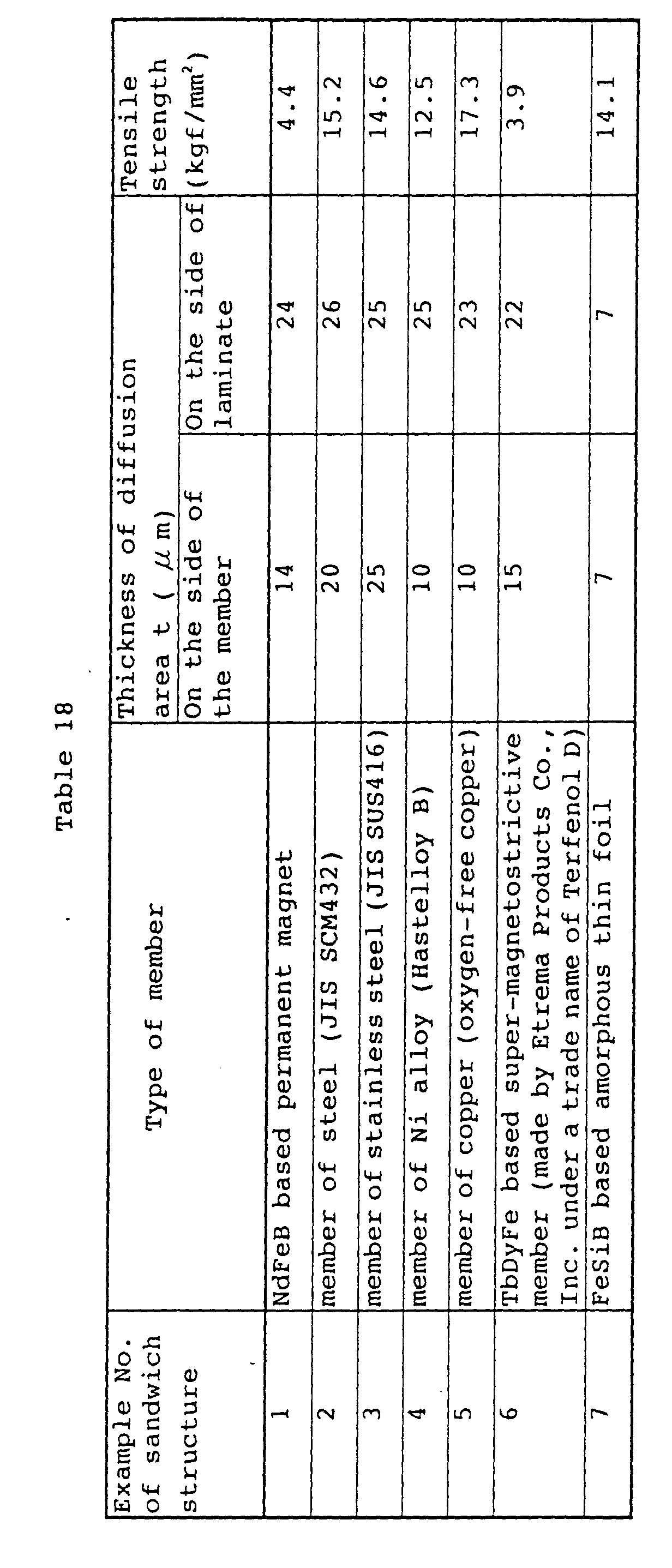
- For each of the examples 2 to 5 and 7 in Table 8, a fracture was produced in the
binding layer 6, but for the example 1, thepermanent magnet 2 was fractured, and for the example 6, the super-magnetostrictive member was fractured. It can be seen from Table 18 that a large bond strength is obtained, notwithstanding that the heating temperature was as low as 440 °C. - The member made of a carbon steel or a stainless steel is hardened by a quenching, but when this member is heated to 750 °C to 900 °C, it is annealed and softened. For the rare earth element-based super-magnetostrictive member, when it is heated to 900 °C or more, a disadvantage occurs that the magnetic characteristic thereof is degraded, because the metallographic structure is varied. However, such disadvantage can be avoided, because the heating temperature T is low in the binding operation using the above-described
brazing filler metal 12. - Then, a brazing filler metal was fabricated in the same manner as described above from the example 2 of the amorphous thin foil made of the Mm72Cu23Al5. Using this brazing filler metal, a binding operation similar to that described above was carried out, thereby producing examples 1 to 6 of sandwich structures A similar to those described above. An example 7 of a similar sandwich structure A was also produced in the same manner. The heating temperature T was set at 420 °C.
- Table 19 shows the results of a tensile strength for the examples 1 to 7 of the sandwich structures A.
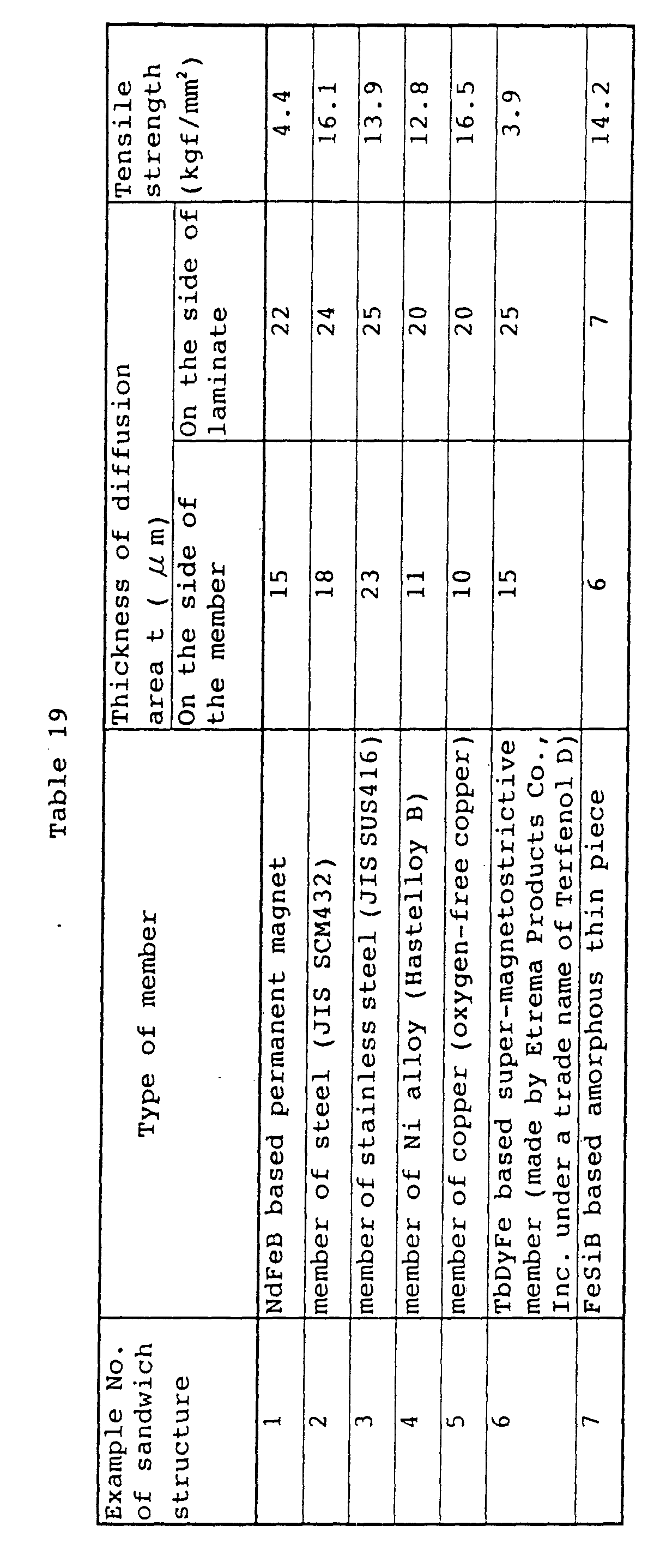
- Likewise, for the examples 2 to 5 and 7, a fracture was produced in the
binding layer 6, but for the example 1, thepermanent magnet 2 was fractured, and for the example 6, the super-magnetostrictive member was fractured. It can be seen from Table 18 that a large bond strength is obtained, notwithstanding that the heating temperature was as low as 420°C. - In an article, a binding layer formed through a heating step exists between a permanent magnet and a laminate of steel plates. The binding layer is formed by producing a liquid phase at the heating step from a brazing filler metal made of a rare earth element-based alloy. Diffusion areas exist between a body portion of the permanent magnet and a body portion of the binding layer and between a body portion of the laminate and the body portion of the binding layer, respectively. The thickness t of each of the diffusion areas is in a range of t ≥ 5 µ m. The bond strength in the article is greatly increased by the provision of the diffusion areas and the specific claimed composition of the brazing filler metal.
Claims (8)
- An article made by joining two metal structural members by a binding layer interposed therebetween comprising, one of said two structural members being made of a permanent magnet including a rare earth element, the other of said two structural members being made of either the same permanent magnet including a rare earth metal or a different metal material than said one structural member, and said binding layer being formed from a brazing filler metaL wherein said two structural members are joined with each other by heating to a temperature sufficient to cause a liquid phase in said binding layer and by producing mutually diffused areas between said one structural member and said binding layer and between said other structural member and said binding layer, respectively, by utilizing said liquid phase, the thickness t of each of said mutually diffused areas being in a range of t≧5 µm and wherein said brazing filler metal forming said binding layer consists of:
Nd in a content of 68 atom %≦Nd≦70 atom %. Cu in a content of 22 atom %≦Cu<30 atom %, and Al in a content of 2 atom %≦Al≦8 atom % - An article according to claim 1. wherein a liquid phase generating temperature Tm of said brazing filler metal made of said rare earth element-based alloy is in a range of Tm≦650°C.
- An article according to claim 1 or 2, wherein said other member is an Fe-based alloy.
- An article according to claims 1-3. wherein a liquid phase generating temperature Tm of said brazing filler metal is in a range of 380° C.≦Tm≦600° C.
- An article made by joining two metal structural members by a binding layer interposed therebetween. comprising, one of said two structural members being made of a supermagnetostrictive member including a rare earth element, the other of said two structural members being made of either the same material as said supermagnetostrictive member including a rare earth element or a different metal material than said one structural member. and said binding layer being formed from a brazing filler metal, wherein said two structural members are joined with each other by heating to a temperature sufficient to cause a liquid phase in said binding layer and by producing mutually diffused areas between said one structural member and said binding layer and between said other structural member and said binding layer, respectively, by utilizing said liquid phase, the thickness t of each of said mutually diffused areas being in a range of t 5≧µm. and wherein said brazing filler metal forming said binding layer consists of: Nd in a content of 68 atom %≦Nd≦70 atom %, Cu in a content of 22 atom %≦Cu≦30 atom %. and Al in a content of 2 atom %≦Al≦8 atom %.
- An article according to claim 5. wherein a liquid phase generating temperature Tm of said brazing filler metal made of said rare earth element-based alloy is in a range of Tm≦650°C.
- An article according to claim 5 or 6. wherein said other member is an Fe-based alloy.
- An article according to claims 5-7, wherein a liquid phase generating temperature Tm of said brazing filler metal is in a range of 380° C≦Tm≦600° C.
Applications Claiming Priority (12)
| Application Number | Priority Date | Filing Date | Title |
|---|---|---|---|
| JP12780494 | 1994-06-09 | ||
| JP127804/94 | 1994-06-09 | ||
| JP12780494 | 1994-06-09 | ||
| JP258453/94 | 1994-10-24 | ||
| JP25845394A JP3382383B2 (en) | 1994-06-09 | 1994-10-24 | Bonding material for metal members |
| JP25845394 | 1994-10-24 | ||
| JP28035494A JP3382392B2 (en) | 1994-11-15 | 1994-11-15 | Brazing material |
| JP280354/94 | 1994-11-15 | ||
| JP28035494 | 1994-11-15 | ||
| JP1948495 | 1995-02-07 | ||
| JP1948495 | 1995-02-07 | ||
| JP19484/95 | 1995-02-07 |
Publications (2)
| Publication Number | Publication Date |
|---|---|
| EP0691175A1 EP0691175A1 (en) | 1996-01-10 |
| EP0691175B1 true EP0691175B1 (en) | 2001-08-29 |
Family
ID=27457204
Family Applications (1)
| Application Number | Title | Priority Date | Filing Date |
|---|---|---|---|
| EP95108943A Expired - Lifetime EP0691175B1 (en) | 1994-06-09 | 1995-06-09 | Article made by joining two members together, and a brazing filler metal |
Country Status (3)
| Country | Link |
|---|---|
| US (2) | US5830585A (en) |
| EP (1) | EP0691175B1 (en) |
| DE (1) | DE69522390T2 (en) |
Cited By (2)
| Publication number | Priority date | Publication date | Assignee | Title |
|---|---|---|---|---|
| CN101885119A (en) * | 2010-06-25 | 2010-11-17 | 常熟市华银焊料有限公司 | Sn-Cu-Ni lead-free solder containing V, Nd and Ge |
| WO2019120490A1 (en) | 2017-12-19 | 2019-06-27 | Abb Schweiz Ag | Multicomponent magnet assemblies for electrical machines |
Families Citing this family (37)
| Publication number | Priority date | Publication date | Assignee | Title |
|---|---|---|---|---|
| EP0691175B1 (en) * | 1994-06-09 | 2001-08-29 | Honda Giken Kogyo Kabushiki Kaisha | Article made by joining two members together, and a brazing filler metal |
| DE19733135C2 (en) * | 1997-07-31 | 2003-03-20 | Fev Motorentech Gmbh | Method for producing a component composed of two sub-elements |
| GB9910392D0 (en) * | 1999-05-05 | 1999-07-07 | Lucas Ind Plc | Rotor for an electrical machine,and an electrical machine including such a rotor |
| US6587742B2 (en) * | 2000-12-20 | 2003-07-01 | Mark Manuel | Method and apparatus for the creation of a tool |
| US7222834B2 (en) * | 2001-08-14 | 2007-05-29 | Floodcooling Technologies, Llc | Tool and a method for making a tool |
| US20040038074A1 (en) * | 2001-11-01 | 2004-02-26 | Mark Manuel | Tool and a method for creating a tool |
| JP2004112849A (en) * | 2002-09-13 | 2004-04-08 | Honda Motor Co Ltd | Permanent magnet type rotor |
| US7338717B2 (en) * | 2002-11-07 | 2008-03-04 | Floodcooling Technologies, Llc | Tool and a method for creating the tool |
| US7195223B2 (en) * | 2002-12-02 | 2007-03-27 | Mark Manuel | System and a method for cooling a tool |
| WO2005065930A1 (en) * | 2003-12-04 | 2005-07-21 | Mark Manuel | A tool and a method for creating a tool |
| US20050196232A1 (en) * | 2004-03-05 | 2005-09-08 | Mark Manuel | Method and an apparatus for the creation of a tangible item, such as a tool and/or a part, and a tangible item |
| US7563091B2 (en) * | 2005-01-18 | 2009-07-21 | Floodcooling Technologies, L.L.C. | Tool having an ejection assembly, a method for making such a tool, and a method for ejecting a formed object from a tool |
| US20060156787A1 (en) * | 2005-01-18 | 2006-07-20 | Mark Manuel | Laminated tool and a method for forming a tool |
| US7278197B2 (en) * | 2005-01-18 | 2007-10-09 | Floodcooling Technologies, Llc | Method for producing a tool |
| US7376484B2 (en) * | 2005-01-18 | 2008-05-20 | Floodcooling Technologies, Llc | Method for building a tool |
| US20070102837A1 (en) * | 2005-09-23 | 2007-05-10 | Mark Manuel | Tool having desired thermal management properties and a method for producing a tool having desired thermal management properties |
| US7379787B2 (en) * | 2005-04-09 | 2008-05-27 | Floodcooling Technologies, Llc | Method for forming a tangible item and a tangible item formed by the method |
| WO2006110091A1 (en) * | 2005-04-15 | 2006-10-19 | Therim Diagnostica Ab | Diagnostic method for detecting cancer by measuring amount of a cytokine like il-6 |
| CN100513623C (en) * | 2005-04-21 | 2009-07-15 | 中国科学院物理研究所 | Cerium-based non-crystalline metal plastics |
| US7628871B2 (en) * | 2005-08-12 | 2009-12-08 | Intel Corporation | Bulk metallic glass solder material |
| US20070039153A1 (en) * | 2005-08-18 | 2007-02-22 | Mark Manuel | Method for forming a tool and a tool |
| US20070040298A1 (en) * | 2005-08-18 | 2007-02-22 | Mark Manuel | Assembly and a method for cooling and/or forming an item |
| US20070067977A1 (en) * | 2005-09-29 | 2007-03-29 | Mark Manuel | Tool and a method for producing a tool |
| CN100357480C (en) * | 2006-05-26 | 2007-12-26 | 浙江大学 | La base bulk amorphous alloy |
| CN100408256C (en) * | 2006-11-26 | 2008-08-06 | 常熟市华银焊料有限公司 | Cadmium-free silver solder containing gallium, indium and cerium |
| CN101440463B (en) * | 2007-11-20 | 2010-12-22 | 比亚迪股份有限公司 | Rare-earth based amorphous alloy and manufacturing method thereof |
| CN101445895B (en) * | 2007-11-26 | 2011-01-26 | 比亚迪股份有限公司 | A rare earth-based amorphous alloy and its preparation method |
| US20090142549A1 (en) * | 2007-11-30 | 2009-06-04 | Floodcooling Technologies, L.L.C. | Fastened connections for laminate tooling |
| US7896224B2 (en) * | 2008-01-30 | 2011-03-01 | Cornell University | Permanent magnet temporary demagnetization temperature rise technique and their application for soldering |
| JP5623368B2 (en) * | 2010-11-05 | 2014-11-12 | 信越化学工業株式会社 | Dipole ring magnetic circuit |
| CN105057918A (en) * | 2015-09-09 | 2015-11-18 | 钢铁研究总院 | Strap-shaped brazing material for rare earth iron-based permanent magnet and preparation method of strap-shaped brazing material |
| CN105081606A (en) * | 2015-09-09 | 2015-11-25 | 钢铁研究总院 | Strap-shaped brazing filler for rare earth cobalt-based permanent magnet and preparing method of strap-shaped brazing filler |
| CN105081498A (en) * | 2015-09-09 | 2015-11-25 | 钢铁研究总院 | Sintered SmCo permanent magnet welding method |
| CN105274383A (en) * | 2015-11-09 | 2016-01-27 | 湖北维维安科技有限公司 | Rare earth (RE)-copper intermediate alloy and preparation method thereof |
| CN106392368A (en) * | 2016-11-28 | 2017-02-15 | 江苏阳明船舶装备制造技术有限公司 | High-temperature Zn-based soft solder for soldering aluminum and copper and welding method |
| CN112719693B (en) * | 2020-12-11 | 2022-08-30 | 哈尔滨工业大学 | Low-temperature magnetic glass solder, preparation method thereof and method for connecting ferrite by using low-temperature magnetic glass solder |
| CN115229378A (en) * | 2022-08-09 | 2022-10-25 | 哈尔滨工业大学(威海) | A kind of high-entropy alloy brazing filler metal and its preparation method and application |
Family Cites Families (22)
| Publication number | Priority date | Publication date | Assignee | Title |
|---|---|---|---|---|
| US2888741A (en) * | 1955-03-22 | 1959-06-02 | American Metallurg Products Co | Alloys |
| US3072476A (en) * | 1955-03-22 | 1963-01-08 | American Metallurg Products Co | Method of alloying |
| US3906617A (en) * | 1970-03-04 | 1975-09-23 | Gte Sylvania Inc | Method of preventing braze and diffusion flow |
| JPS5021485B2 (en) * | 1971-11-22 | 1975-07-23 | ||
| DE2235466C3 (en) * | 1972-07-20 | 1975-03-13 | Basf Ag, 6700 Ludwigshafen | 3-phenylpropanals and 4-phenylbutanals and a process for their preparation |
| US3892599A (en) * | 1973-06-22 | 1975-07-01 | Gen Electric | Air-stable compact of cobalt-rare earth alloy particles and method |
| CH564837A5 (en) * | 1973-06-29 | 1975-07-31 | Bbc Brown Boveri & Cie | |
| US3993844A (en) * | 1974-12-30 | 1976-11-23 | Gte Sylvania Incorporated | Composite ceramic articles and method of making |
| CH612287A5 (en) * | 1975-05-22 | 1979-07-13 | Bbc Brown Boveri & Cie | |
| JPS601940B2 (en) * | 1980-08-11 | 1985-01-18 | 富士通株式会社 | Temperature sensing element material |
| US4496395A (en) * | 1981-06-16 | 1985-01-29 | General Motors Corporation | High coercivity rare earth-iron magnets |
| FR2548687B1 (en) * | 1983-07-05 | 1989-12-01 | Rhone Poulenc Spec Chim | NEODYM ALLOYS AND THEIR MANUFACTURING METHOD |
| US4643347A (en) * | 1984-10-09 | 1987-02-17 | North American Philips Corporation | Mounting hard magnetic material permanent magnets |
| DE3671886D1 (en) * | 1986-01-08 | 1990-07-19 | Philips Nv | COMPOSED BODY. |
| DE3774594D1 (en) * | 1986-03-11 | 1992-01-02 | Philips Nv | COMPOSITE BODY. |
| DE3785720T2 (en) * | 1986-09-25 | 1993-08-12 | Toshiba Kawasaki Kk | METHOD FOR PRODUCING A FILM CARRIER. |
| JPH07122119B2 (en) * | 1989-07-04 | 1995-12-25 | 健 増本 | Amorphous alloy with excellent mechanical strength, corrosion resistance and workability |
| US5015536A (en) * | 1989-07-14 | 1991-05-14 | North American Philips Corporation | Method of mounting permanent magnets without organic adhesives |
| JPH04334490A (en) * | 1991-05-10 | 1992-11-20 | Yoshida Kogyo Kk <Ykk> | optical recording medium |
| JP2804393B2 (en) * | 1991-07-31 | 1998-09-24 | 京セラ株式会社 | Ceramic heater |
| US5405460A (en) * | 1992-03-09 | 1995-04-11 | Nippon Steel Corporation | Fe-Cr-Al alloy steel sheet and process for producing the same |
| EP0691175B1 (en) * | 1994-06-09 | 2001-08-29 | Honda Giken Kogyo Kabushiki Kaisha | Article made by joining two members together, and a brazing filler metal |
-
1995
- 1995-06-09 EP EP95108943A patent/EP0691175B1/en not_active Expired - Lifetime
- 1995-06-09 DE DE69522390T patent/DE69522390T2/en not_active Expired - Fee Related
- 1995-06-17 US US08/480,269 patent/US5830585A/en not_active Expired - Fee Related
-
1998
- 1998-04-21 US US09/063,531 patent/US6214480B1/en not_active Expired - Fee Related
Cited By (3)
| Publication number | Priority date | Publication date | Assignee | Title |
|---|---|---|---|---|
| CN101885119A (en) * | 2010-06-25 | 2010-11-17 | 常熟市华银焊料有限公司 | Sn-Cu-Ni lead-free solder containing V, Nd and Ge |
| CN101885119B (en) * | 2010-06-25 | 2012-01-11 | 常熟市华银焊料有限公司 | Sn-Cu-Ni lead-free solder containing V, Nd and Ge |
| WO2019120490A1 (en) | 2017-12-19 | 2019-06-27 | Abb Schweiz Ag | Multicomponent magnet assemblies for electrical machines |
Also Published As
| Publication number | Publication date |
|---|---|
| US6214480B1 (en) | 2001-04-10 |
| EP0691175A1 (en) | 1996-01-10 |
| DE69522390T2 (en) | 2002-02-14 |
| DE69522390D1 (en) | 2001-10-04 |
| US5830585A (en) | 1998-11-03 |
Similar Documents
| Publication | Publication Date | Title |
|---|---|---|
| US5830585A (en) | Article made by joining two members together, and a brazing filler metal | |
| US4250229A (en) | Interlayers with amorphous structure for brazing and diffusion bonding | |
| JPWO1998031497A1 (en) | Integrated joint structure of rare earth magnet and metal material and joining method thereof | |
| EP0503970A1 (en) | Magnetic refrigerant | |
| WO1996012336A1 (en) | Rotor for rotating machine, method of manufacturing same, and magnet unit | |
| EP0509628B1 (en) | Magnetostrictive alloys and method of manufacturing thereof | |
| CA1069971A (en) | Sec05-permanent magnet joined to at least one iron mass and method of fabricating such a permanent magnet | |
| JP3592425B2 (en) | Rare earth alloy brazing filler metal | |
| JP3802586B2 (en) | Heat joining method using brazing material for two kinds of members with different thermal expansion coefficients | |
| JP3592397B2 (en) | Heat bonding method for two kinds of members having different thermal expansion rates | |
| JP3373950B2 (en) | Heat bonding method of two kinds of members having different thermal expansion coefficients | |
| JP3441197B2 (en) | Paste joining material for brazing | |
| JP3759198B2 (en) | Joining method of workpieces | |
| JP3645925B2 (en) | Joined body and joining method of permanent magnet and different kind of member | |
| JP3382392B2 (en) | Brazing material | |
| US4473400A (en) | Magnetic metallic glass alloy | |
| JPH08309581A (en) | Joined body consisting of two members to be joined | |
| JPH01171215A (en) | Method for manufacturing rare earth-Fe-B magnet laminate | |
| JP3631809B2 (en) | Joining method of workpieces | |
| JP3382383B2 (en) | Bonding material for metal members | |
| JPH08118066A (en) | Method for manufacturing bonded body composed of permanent magnet having anticorrosive ability and dissimilar material member | |
| JPH02250922A (en) | Manufacturing method of rare earth element-transition element-B magnet | |
| JP3472358B2 (en) | Permanent magnet for heat bonding and method of manufacturing the same | |
| JPH0294603A (en) | Rolled anisotropic rare earth magnet and manufacture thereof | |
| JPH09199362A (en) | Method for manufacturing bonded body having permanent magnet material |
Legal Events
| Date | Code | Title | Description |
|---|---|---|---|
| PUAI | Public reference made under article 153(3) epc to a published international application that has entered the european phase |
Free format text: ORIGINAL CODE: 0009012 |
|
| AK | Designated contracting states |
Kind code of ref document: A1 Designated state(s): DE FR GB IT |
|
| 17P | Request for examination filed |
Effective date: 19960424 |
|
| 17Q | First examination report despatched |
Effective date: 19990416 |
|
| GRAG | Despatch of communication of intention to grant |
Free format text: ORIGINAL CODE: EPIDOS AGRA |
|
| GRAG | Despatch of communication of intention to grant |
Free format text: ORIGINAL CODE: EPIDOS AGRA |
|
| GRAH | Despatch of communication of intention to grant a patent |
Free format text: ORIGINAL CODE: EPIDOS IGRA |
|
| GRAH | Despatch of communication of intention to grant a patent |
Free format text: ORIGINAL CODE: EPIDOS IGRA |
|
| GRAA | (expected) grant |
Free format text: ORIGINAL CODE: 0009210 |
|
| AK | Designated contracting states |
Kind code of ref document: B1 Designated state(s): DE FR GB IT |
|
| REF | Corresponds to: |
Ref document number: 69522390 Country of ref document: DE Date of ref document: 20011004 |
|
| REG | Reference to a national code |
Ref country code: GB Ref legal event code: IF02 |
|
| ET | Fr: translation filed | ||
| PLBE | No opposition filed within time limit |
Free format text: ORIGINAL CODE: 0009261 |
|
| STAA | Information on the status of an ep patent application or granted ep patent |
Free format text: STATUS: NO OPPOSITION FILED WITHIN TIME LIMIT |
|
| 26N | No opposition filed | ||
| PGFP | Annual fee paid to national office [announced via postgrant information from national office to epo] |
Ref country code: FR Payment date: 20040608 Year of fee payment: 10 |
|
| PGFP | Annual fee paid to national office [announced via postgrant information from national office to epo] |
Ref country code: GB Payment date: 20040609 Year of fee payment: 10 |
|
| PGFP | Annual fee paid to national office [announced via postgrant information from national office to epo] |
Ref country code: DE Payment date: 20040617 Year of fee payment: 10 |
|
| PG25 | Lapsed in a contracting state [announced via postgrant information from national office to epo] |
Ref country code: IT Free format text: LAPSE BECAUSE OF NON-PAYMENT OF DUE FEES;WARNING: LAPSES OF ITALIAN PATENTS WITH EFFECTIVE DATE BEFORE 2007 MAY HAVE OCCURRED AT ANY TIME BEFORE 2007. THE CORRECT EFFECTIVE DATE MAY BE DIFFERENT FROM THE ONE RECORDED. Effective date: 20050609 Ref country code: GB Free format text: LAPSE BECAUSE OF NON-PAYMENT OF DUE FEES Effective date: 20050609 |
|
| PG25 | Lapsed in a contracting state [announced via postgrant information from national office to epo] |
Ref country code: DE Free format text: LAPSE BECAUSE OF NON-PAYMENT OF DUE FEES Effective date: 20060103 |
|
| PG25 | Lapsed in a contracting state [announced via postgrant information from national office to epo] |
Ref country code: FR Free format text: LAPSE BECAUSE OF NON-PAYMENT OF DUE FEES Effective date: 20060228 |
|
| GBPC | Gb: european patent ceased through non-payment of renewal fee |
Effective date: 20050609 |
|
| REG | Reference to a national code |
Ref country code: FR Ref legal event code: ST Effective date: 20060228 |