EP0691173B1 - Soudage a l'arc de plasma et instrument a cet effet - Google Patents
Soudage a l'arc de plasma et instrument a cet effet Download PDFInfo
- Publication number
- EP0691173B1 EP0691173B1 EP94910537A EP94910537A EP0691173B1 EP 0691173 B1 EP0691173 B1 EP 0691173B1 EP 94910537 A EP94910537 A EP 94910537A EP 94910537 A EP94910537 A EP 94910537A EP 0691173 B1 EP0691173 B1 EP 0691173B1
- Authority
- EP
- European Patent Office
- Prior art keywords
- plasma
- gas
- workpiece material
- flow rate
- welding
- Prior art date
- Legal status (The legal status is an assumption and is not a legal conclusion. Google has not performed a legal analysis and makes no representation as to the accuracy of the status listed.)
- Expired - Lifetime
Links
Images


Classifications
-
- B—PERFORMING OPERATIONS; TRANSPORTING
- B23—MACHINE TOOLS; METAL-WORKING NOT OTHERWISE PROVIDED FOR
- B23K—SOLDERING OR UNSOLDERING; WELDING; CLADDING OR PLATING BY SOLDERING OR WELDING; CUTTING BY APPLYING HEAT LOCALLY, e.g. FLAME CUTTING; WORKING BY LASER BEAM
- B23K10/00—Welding or cutting by means of a plasma
- B23K10/02—Plasma welding
Definitions
- the present invention relates to a plasma arc welding method of welding together a plurality of plate materials laid one over another.
- the plasma arc welding technique especially, the plasma arc spot welding technique is favorably comparable with the conventional electrical resistance spot welding technique in that because of its ability to weld from one side, it is advantageously capable of dealing with large-sized workpieces as well as workpieces which are of an irregular configuration. For this reason, a research and development work has hitherto been extensively conducted for the plasma arc welding technique in respect of a variety of phases thereof.
- Fig. 1 there is shown the sequence of a plasma arc spot welding method as set forth in the above noted prior art publication.
- a plasma arc welding apparatus for cutting or welding metallic material is known from EP-0 480 034.
- contact surfaces between several parts of the plasma torch are arranged on a line running from the nozzle to a torch proper.
- the inside of a cylindrical part of the nozzle is stepped or tapered for enlarging the diameter of the upper part thereof above the swirler except the hole or a part of the seat for the swirler.
- a stability of the plasma arc can be maintained even with a plasma gas flow rate which is less than in the prior art and that for this reason a molten pool in the proximal side workpiece material can stably be brought into contact with the distal side workpiece material.
- the thermal conduction required is accomplished efficiently and with certainty.
- the above mentioned method preferably includes a feature that in the step in which the said molten pool of the said front side workpiece is brought into contact with the said distal side workpiece material, the said pressure which is exerted by the said plasma gas and/or the said shielding gas is adjusted by controlling at least one of a flow rate of the said plasma gas, a flow rate of the said shielding gas, a plasma welding current magnitude and a standoff in accordance with a particular quality of the said proximal side workpiece material and a particular spacing in size which is formed between the said two workpiece materials.
- the said molten pool of the proximal side workpiece material is still more stably brought into contact with the distal side workpiece material.
- the above mentioned range has an above mentioned plasma gas flow rate of 2 to 5.6 liters/min when the above mentioned plasma welding current magnitude lies between 40 to 100 amperes.
- the above-mentioned inventive method is preferably carried out with an articulated robot for supporting the said plasma torch, a plasma power supply connected to the said electrode, a gas supply source connected to the said plasma flushing outlet, and a shielding gas flushing outlet disposed around the gas flushing outlet of the said plasma torch and connected to the said gas supply source or another gas supply source, and is further provided with a control unit for controlling at least one of an operation of the said articulated robot, an electric current from the said plasma power supply and a flow rate of the said plasma gas and/or a flow rate of the said shielding gas from the said gas supply source.
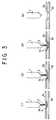
- FIG. 3 there is shown a schematic sequence where one embodiment of a spot welding method according to the present invention is carried out. The steps which are involved in this sequence are listed below.
- the welding conditions in this case are listed in a Table 1 below.
- the nugget diameters shown in Table 1 represent the diameters of the welding bonded areas in plasma spot welding operations.
- Upper Workpiece Material Material SPC Thickness t 2.3 Lower Workpiece Material Material SPC Thickness t 1.8 Welding Time 5.3 sec (Nugget diameter ⁇ 6.0) 8.7 sec (Nugget diameter ⁇ 9.0) Nozzle Diameter ⁇ 4.0
- the pressure which is exerted by the plasma jet 2 and the shielding gas 2a is adjusted by controlling at least one of the flow rate of the plasma gas, the flow rate of the shielding gas, the plasma welding current magnitude and the standoff in accordance with a particular quality of the front side workpiece material 3a and a particular spacing in size between the two workpiece materials 3a and 3b to bring the molten pool 4 in a stabilized state of the front side workpiece material 3a into contact with the rear side workpiece material 3b, it follows that the said molten pool 4 can be still more stably brought into contact with the rear side workpiece material 3b.
- an excessive plasma gas flow rate will bring about a so-called keyhole state in which the intensity of the plasma arc becomes excessive to the extent that a hole may be formed in a workpiece material. Also, if the plasma gas flow rate is too low, the input amount of heat into a workpiece material will be deficient to the extent that a weld penetration deficiency may take place.
- the input amount of heat in contrast to the above, were excessive, resulting in a burn through of the molten pool 4 to the extent that a hole was formed in the workpiece material 3a.
- the gas flow rate was so excessive that the molten pool 4 was thrusted outwards by the plasma gas and the welding portion was formed with a cratered surface, resulting in the formation of a keyhole.
- the lower limit line a for the appropriate plasma welding current I can be set up at 25A from X 1 and X 2 as well as ⁇ 1 and ⁇ 2 .
- the upper limit line b for the appropriate plasma welding current I can be set up at 105A from X 3 and X 4 as well as ⁇ 5 , ⁇ 6 and ⁇ 7 .
- the lower limit line c for the appropriate plasma gas flow rate Q is determined from X 5 and X 6 as well as ⁇ 2 , ⁇ 3 and ⁇ 5 and assumes a curved line rising upwards in the right hand direction. The reason for this is that as the plasma welding current I is increased, a double arc tends to be generated since the gas flowing along the internal surfaces of the nozzle is deficient in its insulation unless the plasma gas flow rate is increased.
- the upper limit line d can be established from X 7 , X 8 and X 9 as well as ⁇ 1 , ⁇ 4 and ⁇ 7 .
- the momentum of the gas will be so increased as to thrust the molten portion outwards and to cause it to be sunk in the form of a crater.
- the above mentioned crater portion will be returned to a plain surface after the heat input is terminated. For this reason, the upper limit line d of this appropriate plasma gas flow rate Q will assume a curve rising in the right hand direction.
- Table 3 there are shown a case for ⁇ 2 in which the plasma welding current I is 40A and the plasma gas flow rate Q is 2 liters/min, a case for ⁇ 3 in which the plasma welding current I is 90A and the plasma gas flow rate Q is 2 liters/min, a case for ⁇ 5 in which the plasma welding current I is 100A and the plasma gas flow rate Q is 2 liters/min, a case for ⁇ 6 in which the plasma welding current I is 100A and the plasma gas flow rate Q is 4.5 liters/min and a case for ⁇ 7 in which the plasma welding current I is 100A and the plasma gas flow rate Q is 5.6 liters/min.
- Fig. 5 there is shown in a perspective view an embodiment of the plasma arc welding apparatus, in which an articulated robot 5 is utilized of which a robot arm 6 has at a frontal end thereof a plasma torch 1 mounted thereon. More specifically, by virtue of the articulated robot 5, the plasma torch 1 is here adapted to meet with an omnidirectional welding operation.
- Numeral 7 designates a plasma welding power supply for supplying an electric current to an electrode of the plasma torch 1 via a high frequency box designated at 8.
- Numeral 16 denotes a gas cylinder for supplying a gas such as argon plus hydrogen into a plasma gas flushing outlet and a shielding gas passage of the plasma torch 1.
- Numeral 9 represents a control unit for controlling the flow rate of the plasma gas, the flow rate of the shielding gas, the plasma welding magnitude and the standoff.
- the above mentioned plasma torch 1 is constructed as shown in Fig. 6.
- An electrode 11 provided in a nozzle 10 has a base portion thereof provided with a swirler 12, by which a plasma gas is caused to flow in a strong swirling stream out towards a frontal end of the electrode 11.
- the above mentioned swirler 12 is constructed as shown in Fig. 7 and is thus provided with a plurality of gas flushing outlets 13 which are oriented in tangential directions relative to a space surrounding the electrode 11. Each flushing outlet 13 is oriented orthogonally to an axis of the electrode 11, or is inclined slightly towards the frontal end side of the electrode 11.
- Numeral 14 designates a shielding cap which is interiorly formed with a shielding gas passage 15 through which a shielding gas is flushed out.
- the above mentioned electrode 11 has a holder 11a composed of copper and has at its frontal end an electrode rod 11b embeded therein and composed of tungsten.
- the plasma current magnitude i.e. welding current magnitude
- the plasma voltage is V 1
- the particle velocity of the plasma arc is V 2
- the plasma torch 1 is provided with the swirler 12 that as noted above is designed to flush the plasma gas in a strong swirling flow around the electrode 11, the arc stability can be maintained even if the frontal end of the electrode 11 has worn away.
- an electrode can be used having a cylindrical tungsten tip embeded in a copper holder thereof.
- an electrode may also be used having a hafnium tip embeded in the copper holder thereof.
- the tungsten tip is then centrally provided with a hole, the arc stability can be increased. Also in this instance, even if the plasma gas flow rate is reduced, the arc can be maintained; and it is thus possible to reduce the pressure that acts on the molten metal.
- a gas containing the oxygen atom as the plasma gas.
- an inexpensive gas such as carbon dioxide can advantageously be used as the plasma gas by virtue of the fact that a swirling flow may be imparted to the plasma gas and that the electrode may have its hafnium tip embeded in its copper holder.
- a form of the nozzle orifice of the above mentioned plasma torch 1 is preferably of a configuration which satisfies the relationship: 1 ⁇ L/D ⁇ 3 where L and D are the length and the diameter of the nozzle, respectively. The reasons for this are set out below.
- the energy required for the plasma arc welding apparatus need only be of a capacity just to melt only a welding area of the workpiece materials and this allows a welding operation to be carried out with an apparatus which is of a comparatively small capacity and also to be performed for even thick plate workpiece materials in a relatively short period of welding time.
- a plasma current magnitude which is determined by workpiece materials
- the development of a particular range for the plasma gas flow rate with which a plasma welding operation is accomplished with a stability has enabled a plasma welding process to be attained for any particular workpiece plate thickness whatsoever.
- a plasma arc welding method according to the present invention are extremely useful in welding together a plurality of workpiece materials which are placed one over another.
Claims (5)
- Procédé de soudage par arc de plasma utilisant une torche à plasma pour le soudage d'un premier matériau d'une pièce (3a) sur un deuxième matériau d'une pièce (3b) qui reposent l'un sur l'autre sur des côtés proximal et distal par rapport à la torche à plasma (1), respectivement,une partie du matériau de la pièce (3a) du côté proximal étant chauffée et fondue par un arc de plasma (2) provenant de la torche à plasma (1) pour former un bain de fusion (4),ledit bain de fusion (4) étant maintenu de manière à ne pas tomber ou chuter sous l'effet d'une tension de surface agissant sur celui-ci et étant amené en contact avec une partie du matériau de la pièce (3b) du côté distal sous une pression qui est exercée par ledit arc de plasma (2) et/ou un gaz inerte (2b), etladite partie du matériau de la pièce (3b) du côté distal étant amenée dans un état fondu par conduction thermique de sorte que lesdits matériaux des pièces (3a;3b) sont soudés ensemble, caractérisé en ce qu'un écoulement tourbillonnaire est fourni à un gaz de plasma dudit arc de plasma (2).
- Procédé de soudage à l'arc de plasma selon la revendication 1, caractérisé en ce que l'étape selon laquelle ledit bain de fusion dudit matériau de la pièce (3a) du côté proximal est amené en contact avec ledit matériau de la pièce (3b) du côté distal, ladite pression qui est exercée par ledit gaz de plasma et/ou ledit gaz inerte (2a) est ajustée en commandant au moins le débit dudit gaz de plasma, le débit du gaz inerte, une amplitude de courant de soudage par plasma et une garde, en fonction d'une qualité particulière dudit matériau de la pièce (3a) du côté proximal et une distance particulière qui est formée entre les deux matériaux de la pièce (3a;3b).
- Procédé de soudage à l'arc de plasma selon l'une des revendications 1 et 2, caractérisé en ce que, par rapport à une amplitude de courant de soudage qui est déterminée par une qualité particulière dudit matériau de la pièce (3a) du côté proximal et une zone liée de soudage particulière, on commande un débit de gaz de plasma de manière à ce qu'il se situe dans une plage particulière.
- Procédé de soudage à l'arc de plasma selon la revendication 3, caractérisé en ce que lorsque l'amplitude du courant de soudage par plasma se situe entre 40 et 100 A, ledit débit du gaz de plasma se situe entre 2 et 5,6 l/mn.
- Procédé de soudage à l'arc de plasma selon l'une quelconque des revendications 1 à 4, dans lequel on utilise un appareil comprenant un robot articulé (5) pour supporter ladite torche à plasma (1), une source (7) d'alimentation du plasma connectée à une électrode (11), une source (16) d'alimentation en gaz connectée à un orifice (13) de sortie de plasma, et un orifice (15) de sortie de gaz inerte disposé autour d'un orifice (13) de sortie de gaz de ladite torche à plasma et relié à ladite source (16) d'alimentation en gaz ou à une autre source d'alimentation en gaz, et est en outre pourvu d'une unité de commande (9) pour la commande d'au moins le fonctionnement du robot articulé, d'un courant électrique provenant de la source (7) d'alimentation en plasma et d'un débit du gaz de plasma et/ou d'un débit dudit gaz inerte provenant de ladite source (16) d'alimentation en gaz.
Applications Claiming Priority (3)
| Application Number | Priority Date | Filing Date | Title |
|---|---|---|---|
| JP68075/93 | 1993-03-26 | ||
| JP6807593 | 1993-03-26 | ||
| PCT/JP1994/000484 WO1994022630A1 (fr) | 1993-03-26 | 1994-03-25 | Soudage a l'arc de plasma et instrument a cet effet |
Publications (3)
| Publication Number | Publication Date |
|---|---|
| EP0691173A1 EP0691173A1 (fr) | 1996-01-10 |
| EP0691173A4 EP0691173A4 (fr) | 1996-03-20 |
| EP0691173B1 true EP0691173B1 (fr) | 1998-09-09 |
Family
ID=13363295
Family Applications (1)
| Application Number | Title | Priority Date | Filing Date |
|---|---|---|---|
| EP94910537A Expired - Lifetime EP0691173B1 (fr) | 1993-03-26 | 1994-03-25 | Soudage a l'arc de plasma et instrument a cet effet |
Country Status (4)
| Country | Link |
|---|---|
| US (1) | US5734144A (fr) |
| EP (1) | EP0691173B1 (fr) |
| DE (1) | DE69413214T2 (fr) |
| WO (1) | WO1994022630A1 (fr) |
Families Citing this family (13)
| Publication number | Priority date | Publication date | Assignee | Title |
|---|---|---|---|---|
| US5938948A (en) * | 1997-07-21 | 1999-08-17 | Ford Global Technologies, Inc. | Plasma arc spot welding of car body steels containing vaporizable ingredients |
| DE19742442B4 (de) * | 1997-09-26 | 2005-07-07 | Raantec Gmbh & Co. Kg | Vorrichtung zum Verschweißen von Kunststoff-Folien |
| DE19847774C2 (de) * | 1998-10-16 | 2002-10-17 | Peter Foernsel | Vorrichtung zur Plasmabehandlung von stab- oder fadenförmigem Material |
| US6677551B2 (en) | 1998-10-23 | 2004-01-13 | Innerlogic, Inc. | Process for operating a plasma arc torch |
| US6498317B2 (en) | 1998-10-23 | 2002-12-24 | Innerlogic, Inc. | Process for operating a plasma arc torch |
| US6326583B1 (en) | 2000-03-31 | 2001-12-04 | Innerlogic, Inc. | Gas control system for a plasma arc torch |
| US6163009A (en) * | 1998-10-23 | 2000-12-19 | Innerlogic, Inc. | Process for operating a plasma arc torch |
| DE20005471U1 (de) * | 2000-03-23 | 2000-06-21 | Benteler Werke Ag | Instrumententräger |
| TWI248846B (en) * | 2003-01-29 | 2006-02-11 | Hon Hai Prec Ind Co Ltd | Electric arc welding method |
| JP5287962B2 (ja) * | 2011-01-26 | 2013-09-11 | 株式会社デンソー | 溶接装置 |
| US9949356B2 (en) | 2012-07-11 | 2018-04-17 | Lincoln Global, Inc. | Electrode for a plasma arc cutting torch |
| US20140183167A1 (en) * | 2012-12-28 | 2014-07-03 | Hyundai Motor Company | Welding device for panel sheets and welding method for the same |
| WO2017125252A1 (fr) * | 2016-01-19 | 2017-07-27 | Linde Aktiengesellschaft | Procédé de soudage à l'arc en atmosphère inerte avec électrode en tungstène |
Citations (1)
| Publication number | Priority date | Publication date | Assignee | Title |
|---|---|---|---|---|
| EP0480034A1 (fr) * | 1989-06-20 | 1992-04-15 | Kabushiki Kaisha Komatsu Seisakusho | Chalumeau au plasma |
Family Cites Families (4)
| Publication number | Priority date | Publication date | Assignee | Title |
|---|---|---|---|---|
| JPS5949112B2 (ja) * | 1977-01-28 | 1984-11-30 | 株式会社東芝 | レ−ザ溶接方法 |
| JPS5794473A (en) * | 1980-12-05 | 1982-06-11 | Honda Motor Co Ltd | Arc spot welding method |
| US4929812A (en) * | 1986-02-20 | 1990-05-29 | Tsentr Nauchno-Tekhnicheskogo Tvorchestva Molodezhi "Astron" | Method for electrical arc spot welding with consumable electrode |
| US5532453A (en) * | 1995-04-07 | 1996-07-02 | W. R. Grace & Co.-Conn. | Process for welding a stack of thin metal sheets |
-
1994
- 1994-03-25 WO PCT/JP1994/000484 patent/WO1994022630A1/fr active IP Right Grant
- 1994-03-25 EP EP94910537A patent/EP0691173B1/fr not_active Expired - Lifetime
- 1994-03-25 DE DE69413214T patent/DE69413214T2/de not_active Expired - Fee Related
- 1994-03-25 US US08/525,530 patent/US5734144A/en not_active Expired - Fee Related
Patent Citations (1)
| Publication number | Priority date | Publication date | Assignee | Title |
|---|---|---|---|---|
| EP0480034A1 (fr) * | 1989-06-20 | 1992-04-15 | Kabushiki Kaisha Komatsu Seisakusho | Chalumeau au plasma |
Also Published As
| Publication number | Publication date |
|---|---|
| WO1994022630A1 (fr) | 1994-10-13 |
| EP0691173A4 (fr) | 1996-03-20 |
| DE69413214T2 (de) | 1999-01-28 |
| US5734144A (en) | 1998-03-31 |
| EP0691173A1 (fr) | 1996-01-10 |
| DE69413214D1 (de) | 1998-10-15 |
Similar Documents
| Publication | Publication Date | Title |
|---|---|---|
| Palani et al. | Selection of parameters of pulsed current gas metal arc welding | |
| Kah et al. | Advanced gas metal arc welding processes | |
| EP1581359B1 (fr) | Soudage mig-plasma | |
| US4463243A (en) | Welding system | |
| Houldcroft | Welding process technology | |
| EP0691173B1 (fr) | Soudage a l'arc de plasma et instrument a cet effet | |
| US4254322A (en) | Narrow weld-groove welding process and apparatus therefor | |
| US5990446A (en) | Method of arc welding using dual serial opposed torches | |
| EP1129808B1 (fr) | Méthode et appareil pour le soudage à l'arc avec électrode consommable | |
| JP2912693B2 (ja) | アルミニウム基材加工物のガス金属アーク溶接方法 | |
| US4162389A (en) | Welding apparatus | |
| US2868950A (en) | Electric metal-arc process and apparatus | |
| AU2007280344A1 (en) | TIG braze-welding with metal transfer in drops at a controlled frequency | |
| WO1994008747A1 (fr) | Inclinaison et enlevement de la bande dure pour tige de forage | |
| US11161191B2 (en) | Process and apparatus for welding workpiece having heat sensitive material | |
| US4090057A (en) | Method for controlling the shape of a molten pool in gas shield arc welding | |
| Ken-Hicken | Gas-tungsten arc welding | |
| JPH0924467A (ja) | 溶接アークを点火するための方法 | |
| Choudhary et al. | A Study on effect of various process variables in gas metal arc welding | |
| Singaravelu et al. | Modified short arc gas metal arc welding process for root pass welding applications | |
| JPS5573479A (en) | Tandem system high speed arc welding method | |
| US4100389A (en) | Method of high speed gas shielded arc welding | |
| Choudhary et al. | A Study on Metal Transfer Mechanism in Gas Metal Arc Welding | |
| JPH06328260A (ja) | プラズマアーク溶接方法 | |
| JP2000254791A (ja) | 軸受用ホワイトメタル合金の肉盛り装置および肉盛り方法 |
Legal Events
| Date | Code | Title | Description |
|---|---|---|---|
| PUAI | Public reference made under article 153(3) epc to a published international application that has entered the european phase |
Free format text: ORIGINAL CODE: 0009012 |
|
| 17P | Request for examination filed |
Effective date: 19950912 |
|
| AK | Designated contracting states |
Kind code of ref document: A1 Designated state(s): DE FR GB IT SE |
|
| A4 | Supplementary search report drawn up and despatched | ||
| AK | Designated contracting states |
Kind code of ref document: A4 Designated state(s): DE FR GB IT SE |
|
| 17Q | First examination report despatched |
Effective date: 19970206 |
|
| GRAG | Despatch of communication of intention to grant |
Free format text: ORIGINAL CODE: EPIDOS AGRA |
|
| GRAG | Despatch of communication of intention to grant |
Free format text: ORIGINAL CODE: EPIDOS AGRA |
|
| GRAH | Despatch of communication of intention to grant a patent |
Free format text: ORIGINAL CODE: EPIDOS IGRA |
|
| GRAH | Despatch of communication of intention to grant a patent |
Free format text: ORIGINAL CODE: EPIDOS IGRA |
|
| GRAA | (expected) grant |
Free format text: ORIGINAL CODE: 0009210 |
|
| AK | Designated contracting states |
Kind code of ref document: B1 Designated state(s): DE FR GB IT SE |
|
| PG25 | Lapsed in a contracting state [announced via postgrant information from national office to epo] |
Ref country code: IT Free format text: LAPSE BECAUSE OF FAILURE TO SUBMIT A TRANSLATION OF THE DESCRIPTION OR TO PAY THE FEE WITHIN THE PRESCRIBED TIME-LIMIT;WARNING: LAPSES OF ITALIAN PATENTS WITH EFFECTIVE DATE BEFORE 2007 MAY HAVE OCCURRED AT ANY TIME BEFORE 2007. THE CORRECT EFFECTIVE DATE MAY BE DIFFERENT FROM THE ONE RECORDED. Effective date: 19980909 Ref country code: FR Free format text: LAPSE BECAUSE OF FAILURE TO SUBMIT A TRANSLATION OF THE DESCRIPTION OR TO PAY THE FEE WITHIN THE PRESCRIBED TIME-LIMIT Effective date: 19980909 |
|
| REF | Corresponds to: |
Ref document number: 69413214 Country of ref document: DE Date of ref document: 19981015 |
|
| PG25 | Lapsed in a contracting state [announced via postgrant information from national office to epo] |
Ref country code: SE Free format text: LAPSE BECAUSE OF FAILURE TO SUBMIT A TRANSLATION OF THE DESCRIPTION OR TO PAY THE FEE WITHIN THE PRESCRIBED TIME-LIMIT Effective date: 19981209 |
|
| EN | Fr: translation not filed | ||
| PG25 | Lapsed in a contracting state [announced via postgrant information from national office to epo] |
Ref country code: GB Free format text: LAPSE BECAUSE OF NON-PAYMENT OF DUE FEES Effective date: 19990325 |
|
| PGFP | Annual fee paid to national office [announced via postgrant information from national office to epo] |
Ref country code: DE Payment date: 19990406 Year of fee payment: 6 |
|
| PLBE | No opposition filed within time limit |
Free format text: ORIGINAL CODE: 0009261 |
|
| STAA | Information on the status of an ep patent application or granted ep patent |
Free format text: STATUS: NO OPPOSITION FILED WITHIN TIME LIMIT |
|
| 26N | No opposition filed | ||
| GBPC | Gb: european patent ceased through non-payment of renewal fee |
Effective date: 19990325 |
|
| PG25 | Lapsed in a contracting state [announced via postgrant information from national office to epo] |
Ref country code: DE Free format text: LAPSE BECAUSE OF NON-PAYMENT OF DUE FEES Effective date: 20010103 |