EP0690246A2 - Fernsteuervorrichtung - Google Patents
Fernsteuervorrichtung Download PDFInfo
- Publication number
- EP0690246A2 EP0690246A2 EP95304264A EP95304264A EP0690246A2 EP 0690246 A2 EP0690246 A2 EP 0690246A2 EP 95304264 A EP95304264 A EP 95304264A EP 95304264 A EP95304264 A EP 95304264A EP 0690246 A2 EP0690246 A2 EP 0690246A2
- Authority
- EP
- European Patent Office
- Prior art keywords
- axis
- bell crank
- ball
- remote control
- crank lever
- Prior art date
- Legal status (The legal status is an assumption and is not a legal conclusion. Google has not performed a legal analysis and makes no representation as to the accuracy of the status listed.)
- Granted
Links
Images


Classifications
-
- F—MECHANICAL ENGINEERING; LIGHTING; HEATING; WEAPONS; BLASTING
- F16—ENGINEERING ELEMENTS AND UNITS; GENERAL MEASURES FOR PRODUCING AND MAINTAINING EFFECTIVE FUNCTIONING OF MACHINES OR INSTALLATIONS; THERMAL INSULATION IN GENERAL
- F16H—GEARING
- F16H61/00—Control functions within control units of change-speed- or reversing-gearings for conveying rotary motion ; Control of exclusively fluid gearing, friction gearing, gearings with endless flexible members or other particular types of gearing
- F16H61/26—Generation or transmission of movements for final actuating mechanisms
- F16H61/36—Generation or transmission of movements for final actuating mechanisms with at least one movement being transmitted by a cable
-
- F—MECHANICAL ENGINEERING; LIGHTING; HEATING; WEAPONS; BLASTING
- F16—ENGINEERING ELEMENTS AND UNITS; GENERAL MEASURES FOR PRODUCING AND MAINTAINING EFFECTIVE FUNCTIONING OF MACHINES OR INSTALLATIONS; THERMAL INSULATION IN GENERAL
- F16H—GEARING
- F16H59/00—Control inputs to control units of change-speed- or reversing-gearings for conveying rotary motion
- F16H59/02—Selector apparatus
- F16H59/04—Ratio selector apparatus
- F16H59/042—Ratio selector apparatus comprising a final actuating mechanism
-
- F—MECHANICAL ENGINEERING; LIGHTING; HEATING; WEAPONS; BLASTING
- F16—ENGINEERING ELEMENTS AND UNITS; GENERAL MEASURES FOR PRODUCING AND MAINTAINING EFFECTIVE FUNCTIONING OF MACHINES OR INSTALLATIONS; THERMAL INSULATION IN GENERAL
- F16H—GEARING
- F16H59/00—Control inputs to control units of change-speed- or reversing-gearings for conveying rotary motion
- F16H59/02—Selector apparatus
- F16H2059/026—Details or special features of the selector casing or lever support
- F16H2059/0269—Ball joints or spherical bearings for supporting the lever
-
- Y—GENERAL TAGGING OF NEW TECHNOLOGICAL DEVELOPMENTS; GENERAL TAGGING OF CROSS-SECTIONAL TECHNOLOGIES SPANNING OVER SEVERAL SECTIONS OF THE IPC; TECHNICAL SUBJECTS COVERED BY FORMER USPC CROSS-REFERENCE ART COLLECTIONS [XRACs] AND DIGESTS
- Y10—TECHNICAL SUBJECTS COVERED BY FORMER USPC
- Y10T—TECHNICAL SUBJECTS COVERED BY FORMER US CLASSIFICATION
- Y10T74/00—Machine element or mechanism
- Y10T74/20—Control lever and linkage systems
- Y10T74/20012—Multiple controlled elements
- Y10T74/20018—Transmission control
- Y10T74/2014—Manually operated selector [e.g., remotely controlled device, lever, push button, rotary dial, etc.]
Definitions
- This invention relates to remote control mechanisms.
- a remote control mechanism comprising a control member pivotable about mutually displaced axes to effect through a pair of control links different modes of operation of a controlled device, the control member being mounted for said pivotal movement about a first ball member, through the geometric centre of which pass said mutually displaced axes, to effect, when pivoted about a first of said mutually displaced axes, an operative movement of a first output member thereby, in use, to displace, one of the control links, and the remote control mechanism also including a second ball member which, in a neutral position of the control member, has its geometric centre lying on an axis essentially coaxial to said first of said mutually displaced axes and is operatively movable, in response to pivotal motion of the control member about the second of said mutually displaced axes, to effect an operative movement of a second output member and thereby, in use, to displace the other control link.
- a remote control mechanism constructed in accordance with the present invention may be used to operate a gear change device of a manual change gear box with the control member being a gear lever which, when pivoted about the second of the mutually displaced axes, displaced said other of the control links, to effect a rail select movement of the gear change device, and which, when pivoted about the first of the mutually displaced axes, displaces the first of the control links to effect a shift movement of the selected rail thereby to change gear.
- the second output member may be constituted by a bell crank lever which is pivotally movable about a fixed axis in response to said operative movement of the second ball member.
- An operative attachment between the second ball member and the bell crank lever may provide for linear movement therebetween in a direction coaxial with said first of the mutually displaced axes to accommodate for pivotal movement of the second ball member out of the plane of the bell crank lever as the second ball member is operatively moved.
- the bell crank lever may be provided with a degree of axial movement along its fixed pivot axis to accommodate for such operative pivotal motion of the second ball member.
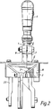
- the remote control mechanism has a control member in the form of a gear lever 1 which is pivotable about mutually perpendicular axes 2 and 3 to effect rail shift and rail select functions, respectlvely, of a gear change device (not shown) of a manual change gear box through respective first and second control links in the form of flexible push-pull control cables 4 and 5.
- the gear lever 1 has a control knob 6 at its upper end and is suitably fast at its lower end in a lever block member as by being a push fit therein with the member 7 being split and clamped against the gear lever by a nut and bolt fastening 8.
- a ball stud 9 is suitably secured to a frame member 10 of the remote control mechanism, the frame member being fashioned so as to enable the mechanism to be mounted to the venicle.
- the ball stud 9 may be screwed at 11 into the frame member 10 and suitably fashioned so as to be tightened home.
- the ball stud a has a spherical ball 12 mounted thereon and retained in position bv the end of the ball stud being peened over the ball, but, preferably, the ball stud and spherical ball are integral with one another and made in one piece.
- the lever block member 7 has a cavity 13 therein with a cylindrical surface 14, and a bearing member 15 is fitted therein and suitably secured in position as by a clrclip 16.
- the bearing member 15 has its bearing surface shaped complementary to the ball 12, by which the gear lever 1 is mounted on the ball both for pivotal movement about the longitudinal axis of the ball stud 9 which axis passes through the geometric centre of the ball 12 and constitutes the axis 2, and about the axis 3 which also passes through the geometric centre of the ball 12 and which is at right angles to the longitudinal axis of the ball stud 9.
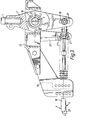
- the push-pull control cable 4 has a linearly movable core 17 which is operably attached to the lower end of the lever block member 7 at any of three vertically spaced apertures 18 therein, the core being slidably mounted in a casing 19 of the cable 4, which casing is clamped against translational movement with the core.
- a second ball stud 20 is suitably secured to the lever block member 7 as by being screwed at 21 thereto and suitably fashioned so as to be tightened home.
- the ball stud 20 has a spherical ball 22 integral therewith.
- the longitudinal axis of the ball stud 20 passes through the geometric centre of the ball 22 and is essentially coaxial with the longitudinal axis of the ball stud 9.
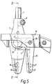
- the second ball 22 is mounted in a complementary shaped surface of a bearing member 23, the external periphery of which is cylindrical and is mounted for translational movement in a cylindrical aperture 24 of a bell crank lever 25.
- the lever 25 is mounted to the frame member 10 for pivotal movement about a fixed axis 26, and the lower end of the lever 25 is provided with three apertures 27 to any of which a linearly movable core 28 of the push-pull control cable 5 may be operably attached. That core 28 is slidably mounted in a casing 29 of the control cable 5, the casing being clamped against translational movement with the core.
- the bell crank lever 25 is fixed to the frame member 10 by a set screw 30. More particularly, a pair of ball races 31 are mounted in the lever 25 and about a bushing 32 mounted in the frame member 10, the bushing receiving the set screw 30, by which the lever 25 can pivot about the axis 26.
- the ball races 31 are separated by a circlip 33 and are mounted between fixed end abutment faces along the pivot axis 26.
- the bearing member 23 is itself restrained from axial movement in the cylindrical aperture of the bell crank lever 25, and in order to accommodate for the arcuate motion of the second ball 22 out of the plane of the lever, the mounting of the lever to the frame member 10 for pivotal movement about the fixed axis 26 provides additionally for a limited movement of the bell crank lever along that axis.
- a flexible boot 34 of an elastomeric material is secured between the second ball stud 20 and the bell crank lever 25 serving as an inhibitor to the ingress of foreign matter to the moving joints between the assembly of the ball 22, bearing member 23 and bell crank lever 25.
- the lever block member 7, bell crank lever 25 and mounting frame member 10 may be of cast aluminium alloy with the ball studs 9 and 20 of steel, and the bearing members 15 and 23 may be of a plastic material.
- the arm of the bell crank lever 25 between the axes 2 and 26 is of fixed length L, it provides a constraint to rotation of the gear lever 1 about a vertical axis as viewed in plan so that the gear lever 1 will only make a minute rotation about that vertical axis when it is moved in its rail select mode.
Landscapes
- Engineering & Computer Science (AREA)
- General Engineering & Computer Science (AREA)
- Mechanical Engineering (AREA)
- Gear-Shifting Mechanisms (AREA)
- Arrangement Or Mounting Of Control Devices For Change-Speed Gearing (AREA)
- Mechanical Control Devices (AREA)
- Control Of Transmission Device (AREA)
Applications Claiming Priority (2)
| Application Number | Priority Date | Filing Date | Title |
|---|---|---|---|
| GB9412932 | 1994-06-28 | ||
| GB9412932A GB9412932D0 (en) | 1994-06-28 | 1994-06-28 | Remote control mechanisms |
Publications (3)
| Publication Number | Publication Date |
|---|---|
| EP0690246A2 true EP0690246A2 (de) | 1996-01-03 |
| EP0690246A3 EP0690246A3 (de) | 1998-03-18 |
| EP0690246B1 EP0690246B1 (de) | 2000-01-19 |
Family
ID=10757432
Family Applications (1)
| Application Number | Title | Priority Date | Filing Date |
|---|---|---|---|
| EP95304264A Expired - Lifetime EP0690246B1 (de) | 1994-06-28 | 1995-06-20 | Fernsteuervorrichtung |
Country Status (5)
| Country | Link |
|---|---|
| US (1) | US5735177A (de) |
| EP (1) | EP0690246B1 (de) |
| JP (1) | JPH0854948A (de) |
| DE (1) | DE69514577T2 (de) |
| GB (2) | GB9412932D0 (de) |
Cited By (3)
| Publication number | Priority date | Publication date | Assignee | Title |
|---|---|---|---|---|
| EP0902218A1 (de) * | 1997-09-12 | 1999-03-17 | Lemförder Metallwaren AG | Handschaltvorrichtung für ein Kraftfahrzeug |
| EP0902214A3 (de) * | 1997-09-10 | 1999-10-27 | Volkswagen Aktiengesellschaft | Schalteinrichtung zur manuellen Betätigung eines Schaltgetriebes |
| FR3049037A1 (fr) * | 2016-03-18 | 2017-09-22 | Peugeot Citroen Automobiles Sa | Dispositif de commande d’une boite de vitesses pour un vehicule automobile comprenant un renvoi de selection |
Families Citing this family (7)
| Publication number | Priority date | Publication date | Assignee | Title |
|---|---|---|---|---|
| US20030213326A1 (en) * | 2002-05-14 | 2003-11-20 | Fett Brian W. | Cable-operated transmission shifters |
| US20050188779A1 (en) * | 2002-08-26 | 2005-09-01 | Jeffrey Lowell | Short shift assembly |
| DE10319705A1 (de) * | 2003-05-02 | 2004-11-25 | Teleflex Morse Gmbh | Schalt-/Wählvorrichtung für das Getriebe eines Fahrzeuges |
| US8424409B2 (en) * | 2008-07-01 | 2013-04-23 | Ghsp, Inc. | Shifter with one-touch assembly |
| US9003917B2 (en) | 2012-02-24 | 2015-04-14 | Dg Auto Sales And Service Llc | Adjustable shifter mechanism |
| USD702165S1 (en) | 2013-01-17 | 2014-04-08 | Daniel Geberth | Floor shifter |
| US11415213B1 (en) * | 2021-03-18 | 2022-08-16 | Loring Smith | Apparatus and method for repair of shift cable ends in various motor vehicles |
Family Cites Families (15)
| Publication number | Priority date | Publication date | Assignee | Title |
|---|---|---|---|---|
| US2250820A (en) * | 1938-12-17 | 1941-07-29 | Fuller Mfg Co | Remote control for transmissions |
| US3707094A (en) * | 1971-01-22 | 1972-12-26 | Trw Inc | Remote shift lever mechanism |
| JPS5632335Y2 (de) * | 1976-10-30 | 1981-08-01 | ||
| JPS53129789A (en) * | 1977-04-19 | 1978-11-13 | Komatsu Ltd | Control level device |
| US4143560A (en) * | 1977-10-19 | 1979-03-13 | General Motors Corporation | Transmission shift control |
| US4245521A (en) * | 1978-05-12 | 1981-01-20 | Grand Haven Stamped Products Company | Manual transmission shifter for operating a transmission with flexible cables |
| JPS5958832U (ja) * | 1982-10-04 | 1984-04-17 | トヨタ自動車株式会社 | シフトアンドセレクト機構のセレクトリタ−ン装置 |
| US4541300A (en) * | 1983-03-28 | 1985-09-17 | Gulf & Western Manufacturing Company | Manually operable gearshift mechanism |
| JPS60136817A (ja) * | 1983-12-26 | 1985-07-20 | Nippon Cable Syst Inc | コントロ−ルケ−ブル用操作装置 |
| US4726249A (en) * | 1985-10-19 | 1988-02-23 | Toyota Jidosha Kabushiki Kaisha | Transmission shift lever assembly |
| US4693135A (en) * | 1986-06-05 | 1987-09-15 | Wickes Manufacturing Company | Manually operable gearshift mechanism |
| US4873884A (en) * | 1987-09-08 | 1989-10-17 | Toyota Jidosha Kabushi Kaisha | Apparatus for supporting shift lever for transmission |
| DE4221762A1 (de) * | 1992-07-02 | 1994-01-05 | Lemfoerder Metallwaren Ag | Schalthebellagerung |
| DE4227413C2 (de) * | 1992-08-19 | 1997-12-04 | Lemfoerder Metallwaren Ag | Schaltvorrichtung zur mechanischen Fernbetätigung eines Wechselgetriebes in einem Kraftfahrzeug |
| US5505103A (en) * | 1994-05-25 | 1996-04-09 | Dura Mechanical Components, Inc. | Ball shifter integrated housing |
-
1994
- 1994-06-28 GB GB9412932A patent/GB9412932D0/en active Pending
-
1995
- 1995-06-20 DE DE69514577T patent/DE69514577T2/de not_active Expired - Fee Related
- 1995-06-20 GB GB9512482A patent/GB2290853B/en not_active Expired - Fee Related
- 1995-06-20 EP EP95304264A patent/EP0690246B1/de not_active Expired - Lifetime
- 1995-06-22 US US08/493,846 patent/US5735177A/en not_active Expired - Fee Related
- 1995-06-27 JP JP7160970A patent/JPH0854948A/ja active Pending
Non-Patent Citations (1)
| Title |
|---|
| None |
Cited By (3)
| Publication number | Priority date | Publication date | Assignee | Title |
|---|---|---|---|---|
| EP0902214A3 (de) * | 1997-09-10 | 1999-10-27 | Volkswagen Aktiengesellschaft | Schalteinrichtung zur manuellen Betätigung eines Schaltgetriebes |
| EP0902218A1 (de) * | 1997-09-12 | 1999-03-17 | Lemförder Metallwaren AG | Handschaltvorrichtung für ein Kraftfahrzeug |
| FR3049037A1 (fr) * | 2016-03-18 | 2017-09-22 | Peugeot Citroen Automobiles Sa | Dispositif de commande d’une boite de vitesses pour un vehicule automobile comprenant un renvoi de selection |
Also Published As
| Publication number | Publication date |
|---|---|
| GB9512482D0 (en) | 1995-08-23 |
| GB9412932D0 (en) | 1994-08-17 |
| DE69514577T2 (de) | 2000-09-14 |
| GB2290853B (en) | 1998-05-06 |
| JPH0854948A (ja) | 1996-02-27 |
| DE69514577D1 (de) | 2000-02-24 |
| GB2290853A (en) | 1996-01-10 |
| EP0690246A3 (de) | 1998-03-18 |
| US5735177A (en) | 1998-04-07 |
| EP0690246B1 (de) | 2000-01-19 |
Similar Documents
| Publication | Publication Date | Title |
|---|---|---|
| EP0690246A2 (de) | Fernsteuervorrichtung | |
| US3939725A (en) | Remote switch actuating device | |
| US5078023A (en) | Thumb-operated throttle control | |
| US4187737A (en) | Control mechanism for hydraulic system | |
| KR870006287A (ko) | 작업차의 밸브조작구조 | |
| AU598227B2 (en) | Transmitter for use with a two-cable shifting mechanism for a transmission | |
| US4363499A (en) | Tiltable steering mechanism for automobiles | |
| DE19547408A1 (de) | Vorrichtung zur Steuerung der Verstellung einer die Leistung eines Motorrad-Motors bestimmenden Drosselklappe | |
| DE3472910D1 (en) | Device for generating a linear movement for manipulators | |
| US4185517A (en) | Control devices | |
| US5029488A (en) | Bearing for the gear shift lever of the gear change box in motor vehicles | |
| CA1334356C (en) | Apparatus for assisting transmission shifting in a marine propulsion device | |
| US4397336A (en) | Control device for hydraulic spool valves | |
| GB2173472A (en) | Manipulator | |
| US5022281A (en) | Arrangement for preselecting and shifting a motor vehicle gear shift transmission | |
| AU774138B2 (en) | Adjustment and assembly system for mechanical cable remote control | |
| EP0097004A3 (de) | Steuervorrichtung | |
| US4501218A (en) | Steering system for a boat | |
| KR960014720A (ko) | 케이블에 의해서 구동되는 자동기어레버 조인트 기구내로 삽입되는 장치 | |
| US3628395A (en) | Transmission control mechanism | |
| JPH0754143B2 (ja) | 手動変速操作装置 | |
| JPH0318771Y2 (de) | ||
| TW255865B (en) | A knob of a gearshift lever for a vehicle | |
| JPH0356688Y2 (de) | ||
| JPS61262824A (ja) | 変速機のコントロ−ル装置 |
Legal Events
| Date | Code | Title | Description |
|---|---|---|---|
| PUAI | Public reference made under article 153(3) epc to a published international application that has entered the european phase |
Free format text: ORIGINAL CODE: 0009012 |
|
| AK | Designated contracting states |
Kind code of ref document: A2 Designated state(s): DE FR IT SE |
|
| PUAL | Search report despatched |
Free format text: ORIGINAL CODE: 0009013 |
|
| AK | Designated contracting states |
Kind code of ref document: A3 Designated state(s): DE FR IT SE |
|
| 17P | Request for examination filed |
Effective date: 19980901 |
|
| 17Q | First examination report despatched |
Effective date: 19981130 |
|
| GRAG | Despatch of communication of intention to grant |
Free format text: ORIGINAL CODE: EPIDOS AGRA |
|
| GRAG | Despatch of communication of intention to grant |
Free format text: ORIGINAL CODE: EPIDOS AGRA |
|
| GRAH | Despatch of communication of intention to grant a patent |
Free format text: ORIGINAL CODE: EPIDOS IGRA |
|
| GRAH | Despatch of communication of intention to grant a patent |
Free format text: ORIGINAL CODE: EPIDOS IGRA |
|
| GRAA | (expected) grant |
Free format text: ORIGINAL CODE: 0009210 |
|
| AK | Designated contracting states |
Kind code of ref document: B1 Designated state(s): DE FR IT SE |
|
| ITF | It: translation for a ep patent filed | ||
| REF | Corresponds to: |
Ref document number: 69514577 Country of ref document: DE Date of ref document: 20000224 |
|
| ET | Fr: translation filed | ||
| PLBE | No opposition filed within time limit |
Free format text: ORIGINAL CODE: 0009261 |
|
| STAA | Information on the status of an ep patent application or granted ep patent |
Free format text: STATUS: NO OPPOSITION FILED WITHIN TIME LIMIT |
|
| 26N | No opposition filed | ||
| PGFP | Annual fee paid to national office [announced via postgrant information from national office to epo] |
Ref country code: DE Payment date: 20060615 Year of fee payment: 12 |
|
| PGFP | Annual fee paid to national office [announced via postgrant information from national office to epo] |
Ref country code: FR Payment date: 20060627 Year of fee payment: 12 |
|
| REG | Reference to a national code |
Ref country code: FR Ref legal event code: ST Effective date: 20080229 |
|
| PG25 | Lapsed in a contracting state [announced via postgrant information from national office to epo] |
Ref country code: DE Free format text: LAPSE BECAUSE OF NON-PAYMENT OF DUE FEES Effective date: 20080101 |
|
| PG25 | Lapsed in a contracting state [announced via postgrant information from national office to epo] |
Ref country code: FR Free format text: LAPSE BECAUSE OF NON-PAYMENT OF DUE FEES Effective date: 20070702 |
|
| PGFP | Annual fee paid to national office [announced via postgrant information from national office to epo] |
Ref country code: IT Payment date: 20080626 Year of fee payment: 14 |
|
| PGFP | Annual fee paid to national office [announced via postgrant information from national office to epo] |
Ref country code: SE Payment date: 20080609 Year of fee payment: 14 |
|
| PG25 | Lapsed in a contracting state [announced via postgrant information from national office to epo] |
Ref country code: IT Free format text: LAPSE BECAUSE OF NON-PAYMENT OF DUE FEES Effective date: 20090620 |
|
| PG25 | Lapsed in a contracting state [announced via postgrant information from national office to epo] |
Ref country code: SE Free format text: LAPSE BECAUSE OF NON-PAYMENT OF DUE FEES Effective date: 20090621 |