EP0689074B1 - Vorrichtung zum Verbinden optischer Fasern - Google Patents
Vorrichtung zum Verbinden optischer Fasern Download PDFInfo
- Publication number
- EP0689074B1 EP0689074B1 EP95303845A EP95303845A EP0689074B1 EP 0689074 B1 EP0689074 B1 EP 0689074B1 EP 95303845 A EP95303845 A EP 95303845A EP 95303845 A EP95303845 A EP 95303845A EP 0689074 B1 EP0689074 B1 EP 0689074B1
- Authority
- EP
- European Patent Office
- Prior art keywords
- support
- tubes
- group
- connector
- tube
- Prior art date
- Legal status (The legal status is an assumption and is not a legal conclusion. Google has not performed a legal analysis and makes no representation as to the accuracy of the status listed.)
- Expired - Lifetime
Links
- 230000003287 optical effect Effects 0.000 title claims description 28
- 239000013307 optical fiber Substances 0.000 claims description 15
- 238000003491 array Methods 0.000 claims description 9
- 239000000835 fiber Substances 0.000 description 8
- 238000009434 installation Methods 0.000 description 2
- 238000000034 method Methods 0.000 description 2
- 230000008602 contraction Effects 0.000 description 1
- 230000004927 fusion Effects 0.000 description 1
- 239000007769 metal material Substances 0.000 description 1
- 238000012986 modification Methods 0.000 description 1
- 230000004048 modification Effects 0.000 description 1
- 239000004033 plastic Substances 0.000 description 1
- 229920003023 plastic Polymers 0.000 description 1
Images


Classifications
-
- G—PHYSICS
- G02—OPTICS
- G02B—OPTICAL ELEMENTS, SYSTEMS OR APPARATUS
- G02B6/00—Light guides; Structural details of arrangements comprising light guides and other optical elements, e.g. couplings
- G02B6/44—Mechanical structures for providing tensile strength and external protection for fibres, e.g. optical transmission cables
- G02B6/4439—Auxiliary devices
- G02B6/4457—Bobbins; Reels
- G02B6/4458—Coiled, e.g. extensible helix
-
- G—PHYSICS
- G02—OPTICS
- G02B—OPTICAL ELEMENTS, SYSTEMS OR APPARATUS
- G02B6/00—Light guides; Structural details of arrangements comprising light guides and other optical elements, e.g. couplings
- G02B6/44—Mechanical structures for providing tensile strength and external protection for fibres, e.g. optical transmission cables
- G02B6/4439—Auxiliary devices
- G02B6/444—Systems or boxes with surplus lengths
- G02B6/4452—Distribution frames
- G02B6/44524—Distribution frames with frame parts or auxiliary devices mounted on the frame and collectively not covering a whole width of the frame or rack
-
- G—PHYSICS
- G02—OPTICS
- G02B—OPTICAL ELEMENTS, SYSTEMS OR APPARATUS
- G02B6/00—Light guides; Structural details of arrangements comprising light guides and other optical elements, e.g. couplings
- G02B6/44—Mechanical structures for providing tensile strength and external protection for fibres, e.g. optical transmission cables
- G02B6/4439—Auxiliary devices
- G02B6/444—Systems or boxes with surplus lengths
- G02B6/44528—Patch-cords; Connector arrangements in the system or in the box
-
- G—PHYSICS
- G02—OPTICS
- G02B—OPTICAL ELEMENTS, SYSTEMS OR APPARATUS
- G02B6/00—Light guides; Structural details of arrangements comprising light guides and other optical elements, e.g. couplings
- G02B6/44—Mechanical structures for providing tensile strength and external protection for fibres, e.g. optical transmission cables
- G02B6/4439—Auxiliary devices
- G02B6/444—Systems or boxes with surplus lengths
- G02B6/4453—Cassettes
- G02B6/4455—Cassettes characterised by the way of extraction or insertion of the cassette in the distribution frame, e.g. pivoting, sliding, rotating or gliding
Definitions
- This invention relates to apparatus for use in interconnecting optical fibres, and more particularly to such an apparatus in which the interconnections are located on a support which is slidably moveable between a retracted position and an extended position, whereby the interconnections can be accessed.
- An object of the present invention is to enable this problem to be overcome.
- EP-A-408266 cited during examination discloses apparatus for use in interconnecting optical fibres, comprising a support, means for locating interconnections between the fibres on said support, support means for slidably supporting said support for movement between a retracted position and an extended position, and at least one flexible tube connectable to said support for receiving and guiding at least one optical fibre, which is to be fed therethrough in use, to said support.
- the present invention provides apparatus for use in interconnecting optical fibres, comprising a support, means for locating interconnections between the fibres on said support, support means for slidably supporting said support for movement between a retracted position and an extended position, and at least one flexible tube connectable to said support for receiving and guiding at least one optical fibre, which is to be fed therethrough in use, to said support characterised in that the or each tube has a substantially helical configuration over at least a portion of its extent locatable behind said support for accommodating said sliding movement of said support, in that said apparatus further comprises means for slidably supporting said support means for movement between a retracted position and an extended position in the same direction as said sliding movement of said support and in that said apparatus further comprises a connector array locatable on or to at least one of the two opposed sides of the apparatus which extend in the direction of said sliding movement for connecting said tubes to ducting means located to the or each side for ducting optical fibres to the apparatus, wherein the or each connector array is mounted on said support means and extends
- the present invention also provides apparatus for use in interconnecting optical fibres, comprising a support means for locating interconnections between the fibres on said support, support means for slidably supporting said support for movement between a retracted position and an extended position, and at least one flexible tube connectable to said support for receiving and guiding at least one optical fibre, which is to be fed therethrough in use, to said support characterised in that the or each tube has a substantially helical configuration over at least a portion of its extent locatable behind said support for accommodating said sliding movement of said support, wherein the support means is fixedly mounted to a wall, rack or the like, wherein said apparatus further comprises a connector array locatable on or to at least one of the two opposed sides of the apparatus which extend in the direction of said sliding movement for connecting said tubes to ducting means located to the or each side for ducting optical fibres to the apparatus, and wherein the or each connector array is mounted to said support means or the part to which said support means is fixed and extends in a direction which is the direction of said sliding
- the helical configuration is able to stretch along its axis when the support is slid from its retracted position to its extended position and to contract along its axis when the support is slid from its extended position to its retracted position whilst maintaining bend radii greater than a predetermined minimum radius and without any accompanying stretching or contraction, or kinking or any other deformation, of the tube itself.
- the apparatus comprises a plurality of said tubes, each being connectable to one end of a respective further tube located on said support, the other ends of said further tubes being connected to said interconnection locating means.
- each of these embodiments comprise tube connector means on said support for connecting said tubes with said further tubes, said connector means providing a releasable connection for said tubes and/or said further tubes, whereby each tube is selectively connectable to any one of a plurality of further tubes. This is advantageous since it allows the selective routeing of fibres in the tubes to the interconnection locating means.
- the connector means may comprise at least one block providing a plurality of through-passages and means for connecting said tubes and further tubes to respective ends of said through passages.
- the interconnection locating means may comprise at least one bank of housings on said support, each housing being adapted to locate at least one connection between two optical fibres.
- each housing in each bank is moveable out of alignment with the remainder of said housings thereof for providing access to the or each optical fibre connection located therein.
- At least one further housing accommodating a passive optical device and provided with input/output connections for test purposes may be associated with each or at least one bank of housings.
- Two of said connector arrays may be provided one on or to each of said sides, and in this case said tubes may be spaced apart behind said support between said sides, a first group of tubes being closer to one of said sides and a second group of tubes being closer to the other of said sides, wherein some of the said first group tubes and some of said second group tubes are connected to the connector array on or to said one side and the remainder of said first group tubes and the remainder of said second group tubes are connected to the connector array on or to said other side.
- the apparatus 10 illustrated therein comprises a support 12, hereinafter referred to as a shelf, which supports means, generally referenced 14, for locating interconnections between optical fibres.
- the shelf 12 is slidably supported by a support means 16, hereinafter referred to as an intermediate shelf, for movement between a retracted position ( Figure 2) and an extended position relative to the intermediate shelf 16.
- the extended position provides access to the fibre interconnection locating means 14.
- the intermediate shelf 16 is itself slidably supported by a support means 18 which is mountable to a wall, rack or the like so as to extend substantially horizontally therefrom.
- the support means comprises two brackets 18A and 18B which in use are mounted by means of respective flanges 20A and 20B a predetermined distance apart to slidably support the intermediate shelf 16 for movement between a retracted position and an extended position in the same direction as the direction of sliding movement of the shelf 12.
- the components 12, 16 and 18 are provided with conventional slideways (not shown) to provide said sliding movement between the shelf 12 and intermediate shelf 16 and between the intermediate shelf 16 and the brackets 18.
- the apparatus when the apparatus is in a fully contracted condition with both the shelf and the intermediate shelf in their retracted positions, (i) the shelf 12 may be moved to its extended position, (ii) the intermediate shelf 16 may be moved to its extended position, and (iii) both the shelf and the intermediate shelf may be moved to their respective extended positions.
- the apparatus is mounted in vertical banks with similar apparatus and with optical fibres interconnected in the apparatus running up or down one or more usually both sides of these banks.
- movement of the shelf 12 to its extended position relative to the intermediate shelf 16 provides access to components on the shelf 12 and movement of the intermediate shelf 16 to its extended position relative to the brackets 18 provides access to components on the intermediate shelf from the front of the apparatus.
- each shelf 12 in a vertical bank of apparatus may be moved independently of the other shelves.
- each flexible tube 22 has a substantially helical configuration over at least a portion 24 of its extent which is located behind the shelf 12 for accommodating the sliding movement of the shelf between its retracted position (as illustrated in Figure 2) and its extended position.
- the portion of helical configuration comprises a plurality of turns, but it is to be understood that this portion may comprise only one turn.
- Each flexible tube 22 is formed of a plastics or metal material and is preformed with its helically configured portion 24.
- the helically configured portion is able to stretch from its normal, unstressed condition which it adopts when the shelf 12 is in its retracted position, to accommodate movement of the shelf when the shelf is slid from its retracted position to its extended position, and to contract back to its normal position when the shelf 12 is slid back to its retracted position.
- the tube itself does not stretch or contract and the bend radii of the turns of the helical portion are arranged to be greater than the predetermined minimum bend radius of the optical fibre guided thereby.
- the wall thickness and/or configuration is such that there will be no damage to a fibre within the tube caused for example by kinking or other deformation during such movement.
- Each flexible tube 22 is connected with a respective further tube 26 located on the shelf and connected to the fibre interconnection location means 14. Connection between a tube 22 and a further tube 26 is via a connector means 28 on the shelf 12 which provides a releasable connection for at least one of the tubes 22, 26 so that each tube 22 may be selectively connected to any one of a plurality of tubes 26.
- the connector means comprises a plurality of connector devices or blocks 30, each of which provides a plurality of through-passages and means for connecting the tubes 22 and further tubes 26 to respective ends of the through passages.
- Figure 2 illustrates the connection of one tube 22 to one tube 26 via a block 30 and a through-passage 32 therein.
- Each connector array 34 comprises a plurality of devices having through-passages 38 to the inner ends of which are connected respective tubes 22 and the outer ends of which are connectable to fibre ducting means (not shown), which may also comprise tubes, located to each side of the apparatus for ducting optical fibres to the apparatus.
- the tubes 22 are spaced apart behind the shelf 12 between the opposed sides 36, 37.
- a first group 40 of eight tubes is closer to the side 36 than the side 37 and a second group 42 of eight tubes is closer to the side 37 than the side 36.
- the interconnecting means 14 comprises two banks 44, 46 of housings 48, bank 44 being closer to side 36 than side 37 and bank 46 being closer to side 37 than side 36.
- the first group 40 of tubes 22 are connected to further tubes 26 connected to the bank 44 and the second group 42 of tubes are connected to further tubes connected to the bank 46.
- the tubes 22 are connected to the underside of connector blocks 30 and the tubes 26 to the uppersides thereof.
- Each bank 44, 46 has two associated connector blocks 30.
- these blocks are referenced 30A, B, C and D.
- Blocks 30A and B are connected to tubes 22 from group 40, block 30A being connected to tubes 22 in that group connected to the connector array on side 37 and block 30B being connected to the tubes 22 in the same group connected to the connection array on side 36.
- Blocks 30C and D on the other hand are connected to tubes 22 from group 42, block 30C being connected to the tubes 22 in that group connected to the connector array on side 37 and block 30D being connected to the connector array on side 36.
- bank 44 is shown arranged for connecting two optical fibres from side 37, which have been guided to block 30A, to two optical fibres from side 36, which have been guided to block 30B.
- each of the four through passages 32 in each block has a respective tube 22 connected to its lower end and each tube 26 may be connected to a selected one of the through-passages at its upper end to form a continuous passageway from one of the connector arrays to one of the banks.
- Each housing 48 in each bank thereof is adapted to locate at least one connection between two optical fibres guided thereto.
- Each housing also includes storage space for housing excess fibre length and is provided with path defining means for locating the fibres within the housing along paths which do not have bends with radii less than the predetermined minimum bend radius of the optical fibres.
- Each housing 48 in each bank 44, 46 is moveable out of alignment with the remainder of the housings in its bank in order to provide access to the or each optical fibre connection therein or the locations for such connections.
- each housing 48 is pivotably mounted with respect to the other housings in its bank about a respective vertical axis 50 indicated by reference 50 in Figure 4.
- housings may be substantially the same as the housings for housing optical fibre connections disclosed in our co-pending UK Patent Application No. 9320101.0 to which attention is directed if further information is required.
- Each bank 44, 46 may have associated with it at least one housing accommodating a passive optical device and provided with connections for test purposes. In practice each such further housing would be provided in the in place of a housing 48.
- the second embodiment differs for the first embodiment in that the intermediate shelf 16, which slidably supports the shelf 12, is fixedly mounted to the wall, rack or the like, to which the support brackets 18 of the first embodiment are mounted, either directly or via mounting brackets. Since the intermediate shelf 16 itself is not slidably mounted, access to the connector arrays 34 would be limited if the connector arrays were mounted on the shelf extending in the direction of sliding movement as in the first embodiment.
- each connector array 34 is mounted to the intermediate shelf 16 or a part, such as a rack part, to which the intermediate shelf 16 is fixed, to extend in a direction which is transverse the direction of sliding movement.
- the connector arrays 34 are located to each side of the apparatus at the front thereof and are readily accessible.
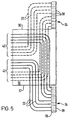
- the tubes 22 are arranged in two groups 40, 42 as in the first embodiment and for the sake of clarity the tubes 22 connected to the connector array 34 to side 36 of the apparatus have been illustrated by broken lines.
- each of the disclosed apparatus enables optical fibres to each side of the apparatus to be interconnected in a managed way using the tubes 22 and 26 to guide the fibres to desired housings 48 for interconnection therein. It will also be understood that the use of connector blocks 30 for making connections between the tubes 22 and 26 provides for flexibility in the routeing of fibres within the apparatus.
- the apparatus will be used for interconnecting an optical fibre running on one side of the apparatus to an optical fibre running on the other side thereof.
- the shelf 12 is moved to its extended position to provide access to the banks 44, 46 of housings 48
- the intermediate shelf 16 is moved to its extended position to provide access to the connector arrays 34.
- a particular housing 48 is selected for locating the connection and pivoted out of alignment with the other housings in its bank.
- a respective tube 22 extending from each of the connector arrays 34 is connected to a further tube extending from that housing. The fibres are then fed through the respective tubes 22 and further tubes connected thereto into the housing 48. If the intermediate shelf 16 is slidable, it is then slid back to its retracted position.
- the fibres are interconnected, typically by being fusion spliced together, and the interconnection and any excess fibre is located in the housing.
- the housing is pivoted back into alignment with the other housings in its bank and the shelf 12 slid back to its retracted position.
- an optical fibre assembly for blown installation comprising an optical fibre unit comprising at least one optical fibre is blown through a tube 22 and a further tube 26 connected thereto from the connector of the connector array 34 to which the tube 22 is connected directly into the housing 48 to which the further tube 26 is connected.
Landscapes
- Physics & Mathematics (AREA)
- General Physics & Mathematics (AREA)
- Optics & Photonics (AREA)
- Light Guides In General And Applications Therefor (AREA)
- Mechanical Coupling Of Light Guides (AREA)
Claims (10)
- Vorrichtung zur Verwendung beim Verbinden von optischen Fasern mit einer Stütze (12), einer Einrichtung (14) zum Lokalisieren von Verbindungen zwischen den Fasern auf der Stütze (12), einer Stützeinrichtung (16) zum gleitbaren Stützen der Stütze (12) zur Bewegung zwischen einer zurückgezogenen Position (Fig. 2) und einer ausgezogenen Position und wenigstens einem flexiblen Rohr (22), das mit der Stütze (12) verbindbar ist, zum Aufnehmen und Führen wenigstens einer optischen Faser, welche bei einer Verwendung dort hindurch zu führen ist, zur Stütze, dadurch gekennzeichnet, dass das oder jedes Rohr (22) eine im Wesentlichen schraubenförmige Konfiguration über wenigstens einem Teil (24) von seinem Ausmaß hat, das hinter der Stütze (12) lokalisierbar ist, zum Unterbringen der gleitenden Bewegung der Stütze, dass die Vorrichtung weiterhin eine Einrichtung (18) zum gleitbaren Stützen der Stützeinrichtung (16) für eine Bewegung zwischen einer zurückgezogenen Position und einer ausgezogenen Position in derselben Richtung wie die Gleitbewegung der Stütze (12) aufweist und dass die Vorrichtung weiterhin ein Anschlussstückfeld (34) aufweist, das an oder zu wenigstens einer der zwei gegenüberliegenden Seiten der Vorrichtung lokalisierbar ist und das sich in der Richtung der gleitenden Bewegung zum Verbinden der Rohre (22) mit einer Führungseinrichtung erstreckt, die an der oder an jeder Seite angeordnet ist, um optische Fasern zur Vorrichtung zu führen, und wobei das oder jedes Anschlussstückfeld (34) an der Stützeinrichtung (16) angebracht ist und sich im Wesentlichen in der Richtung der gleitenden Bewegung erstreckt (Fig. 3).
- Vorrichtung zur Verwendung beim Verbinden von optischen Fasern miteinander, mit einer Stütze (12), einer Einrichtung (14) zum Lokalisieren von Verbindungen zwischen den Fasern an der Stütze (12), einer Stützeinrichtung (16) zum gleitenden Stützen der Stütze (12) für eine Bewegung zwischen einer zurückgezogenen Position (Fig. 2) und einer ausgezogenen Position und wenigstens einem flexiblen Rohr (22), das mit der Stütze (12) verbindbar ist, zum Aufnehmen und Führen von wenigstens einer optischen Faser, die bei einer Verwendung dort hindurch zu führen ist, zu der Stütze, dadurch gekennzeichnet, dass das oder jedes Rohr (22) eine im Wesentlichen schraubenförmige Konfiguration über wenigstens einem Teil (24) seines Ausmaßes hat, das hinter der Stütze (12) lokalisierbar ist, zum Unterbringen der gleitenden Bewegung der Stütze, wobei die Stützeinrichtung (16) an einer Wand, einem Gestell oder ähnlichem fest montiert ist, wobei die Vorrichtung weiterhin ein Anschlussstückfeld (34) aufweist, das an oder zu wenigstens einer der zwei gegenüberliegenden Seiten der Vorrichtung lokalisierbar ist und das sich in der Richtung der gleitenden Bewegung zum Verbinden der Rohre (22) mit einer Führungseinrichtung erstreckt, die an der oder jeder Seite angeordnet ist, um optische Fasern zur Vorrichtung zu führen, wobei das oder jedes Anschlussstückfeld (34) an der Stützeinrichtung (16) angebracht ist, oder an dem Teil, an welchem die Stützeinrichtung fixiert ist, und sich in einer Richtung erstreckt, die die Richtung der gleitenden Bewegung ist (Fig. 3).
- Vorrichtung nach Anspruch 1 oder 2, mit einer Vielzahl der Rohre (22), die jeweils an einem Ende eines jeweils weiteren Rohrs (26) anschließbar sind, das an der Stütze (12) angeordnet ist, wobei die anderen Enden der weiteren Rohre (26) mit der Verbindungslokalisierungseinrichtung (14) verbunden sind.
- Vorrichtung nach Anspruch 3, mit einer Rohrverbindungseinrichtung (28) an bzw. auf der Stütze (12) zum Verbinden der Rohre (22) mit den weiteren Rohren (26), wobei die Verbindungseinrichtung (28) eine lösbare Verbindung für die Rohre und/oder die weiteren Rohre zur Verfügung stellt, wobei jedes Rohr selektiv mit irgendeinem einer Vielzahl von weiteren Rohren verbindbar ist.
- Vorrichtung nach Anspruch 4, wobei die Verbindungseinrichtung (28) wenigstens einen Block (30) aufweist, der eine Vielzahl von Durchgängen (32) und eine Einrichtung zum Verbinden der Rohre und weiterer Rohre mit jeweiligen Enden der Durchgänge zur Verfügung stellt.
- Vorrichtung nach Anspruch 3, 4 oder 5, wobei die Verbindungslokalisierungseinrichtung (14) wenigstens eine Bank (44, 46) von Gehäusen (48) an bzw. auf der Stütze (12) aufweist, wobei jedes Gehäuse (48) dazu geeignet ist, wenigstens eine Verbindung zwischen zwei optischen Fasern zu lokalisieren.
- Vorrichtung nach Anspruch 6, wobei jedes Gehäuse (48) in der Bank (44, 46) aus einer Ausrichtung mit dem Rest der Gehäuse davon bewegbar ist, um einen Zugriff auf die oder jede optische Faserverbindung, die darin lokalisiert ist, zur Verfügung zu stellen.
- Vorrichtung nach Anspruch 6 oder 7, wobei der oder wenigstens einer der Bank (44, 46) von Gehäusen (48) wenigstens ein weiteres Gehäuse zugeordnet ist, das eine passive optische Vorrichtung unterbringt und mit Eingangs/Ausgangs-Anschlüssen für Testzwecke versehen ist.
- Vorrichtung nach einem der Ansprüche 1 bis 8, mit zwei der Anschlussstückfelder (34), und zwar einem an der oder an jeder der Seiten, und wobei die Rohre (22) hinter der Stütze (12) zwischen den Seiten voneinander beabstandet sind, wobei eine erste Gruppe (40) von Rohren näher zu einer der Seiten (36) ist und eine zweite Gruppe (42) von Rohren näher zur anderen der Seiten (37) ist, wobei einige der Rohre der ersten Gruppe und einige der Rohre der zweiten Gruppe mit dem Anschlussstückfeld an oder zu der einen Seite verbunden sind und der Rest der Rohre der ersten Gruppe und der Rest der Rohre der zweiten Gruppe mit dem Anschlussstückfeld an oder zu der anderen Seite verbunden sind.
- Vorrichtung nach Anspruch 9, wenn er auf Anspruch 6, 7 oder 8 bezogen ist, wobei zwei der Bänke (44, 46) an bzw. auf der Stütze (12) angeordnet sind, von welchen eine erste (44) näher zur einen Seite (36) als zur anderen Seite ist und von welchen die zweite (46) näher zur anderen Seite (37) als zur einen Seite ist, und wobei die erste Gruppe (40) von Rohren (42) mit weiteren Rohren (26) verbunden ist, die mit der ersten Bank (44) verbunden sind, und die zweite Gruppe (42) von Rohren (22) mit weiteren Rohren (26) verbunden ist, die mit der zweiten Bank (46) verbunden sind.
Applications Claiming Priority (2)
| Application Number | Priority Date | Filing Date | Title |
|---|---|---|---|
| GB9412368 | 1994-06-20 | ||
| GB9412368A GB2291209B (en) | 1994-06-20 | 1994-06-20 | Optical fibre organiser having guiding tube for optical fibre |
Publications (2)
| Publication Number | Publication Date |
|---|---|
| EP0689074A1 EP0689074A1 (de) | 1995-12-27 |
| EP0689074B1 true EP0689074B1 (de) | 2002-08-28 |
Family
ID=10757030
Family Applications (1)
| Application Number | Title | Priority Date | Filing Date |
|---|---|---|---|
| EP95303845A Expired - Lifetime EP0689074B1 (de) | 1994-06-20 | 1995-06-06 | Vorrichtung zum Verbinden optischer Fasern |
Country Status (10)
| Country | Link |
|---|---|
| US (1) | US5550947A (de) |
| EP (1) | EP0689074B1 (de) |
| AU (2) | AU679849B2 (de) |
| BR (1) | BR9502251A (de) |
| CA (1) | CA2152125C (de) |
| DE (1) | DE69527892T2 (de) |
| ES (1) | ES2181753T3 (de) |
| GB (2) | GB2312969B (de) |
| NZ (1) | NZ272348A (de) |
| ZA (1) | ZA955028B (de) |
Families Citing this family (5)
| Publication number | Priority date | Publication date | Assignee | Title |
|---|---|---|---|---|
| DE29721956U1 (de) * | 1997-12-12 | 1998-04-23 | BICC KWO Kabel GmbH, 12459 Berlin | Garnitur für Lichtwellenleiter-Kabel |
| US7071824B2 (en) * | 1999-07-29 | 2006-07-04 | Micron Technology, Inc. | Radio frequency identification devices, remote communication devices, identification systems, communication methods, and identification methods |
| ATE401586T1 (de) * | 2002-10-11 | 2008-08-15 | 3M Innovative Properties Co | Schublade zur handhabung von optischen fasern |
| EP1549980B1 (de) | 2002-10-11 | 2008-12-10 | 3M Innovative Properties Company | Spleisskassettenaufbewahrungssystem |
| EP1693694B1 (de) * | 2005-02-16 | 2014-10-29 | 3M Innovative Properties Company | Modularer Kabelkopf für optische Netzwerke |
Family Cites Families (22)
| Publication number | Priority date | Publication date | Assignee | Title |
|---|---|---|---|---|
| FR2515466B1 (fr) * | 1981-10-23 | 1987-01-09 | Lignes Telegraph Telephon | Dispositif de raccordement d'un cable de transmission, notamment d'un cable a fibres optiques, a des equipements electroniques |
| DE3367981D1 (en) | 1982-11-08 | 1987-01-15 | British Telecomm | Optical fibre transmission lines |
| FR2538918A1 (fr) * | 1983-01-05 | 1984-07-06 | Telecommunications Sa | Boite de raccordement et de brassage pour fibres optiques |
| US4648168A (en) * | 1983-12-19 | 1987-03-10 | N.V. Raychem S.A. | Optical fibre breakout |
| US4765710A (en) * | 1985-07-30 | 1988-08-23 | Siemens Aktiengesellschaft | Distributing frame for optical waveguides and the like |
| FR2587127B1 (fr) * | 1985-09-06 | 1987-10-23 | Valleix Paul | Structure pour connexions optiques |
| US4792203A (en) * | 1985-09-17 | 1988-12-20 | Adc Telecommunications, Inc. | Optical fiber distribution apparatus |
| DE3806136A1 (de) * | 1988-02-26 | 1989-09-07 | Rheydt Kabelwerk Ag | Anordnung und verfahren zum bevorraten optischer adern |
| US4898448A (en) * | 1988-05-02 | 1990-02-06 | Gte Products Corporation | Fiber distribution panel |
| US4900123A (en) * | 1988-08-29 | 1990-02-13 | Gte Products Corporation | 1550 nm fiber distribution panel |
| US5071211A (en) * | 1988-12-20 | 1991-12-10 | Northern Telecom Limited | Connector holders and distribution frame and connector holder assemblies for optical cable |
| GB8915846D0 (en) * | 1989-07-11 | 1989-08-31 | Bicc Plc | Termination system for optical fibres |
| AU6278290A (en) * | 1989-09-29 | 1991-04-28 | Northern Telecom Limited | Connector holders and distribution frame and connector holder assemblies for optical cable |
| CA2043759A1 (en) * | 1990-06-04 | 1991-12-05 | Graham R. Handley | Termination system for optical fibres |
| CA2041115A1 (en) * | 1990-07-11 | 1992-01-12 | Mark A. Anton | Fiber optic connector module |
| EP0477574A1 (de) * | 1990-09-25 | 1992-04-01 | Siemens Aktiengesellschaft | Verteilereinrichtung für Lichtwellenleiter |
| US5093887A (en) * | 1990-09-28 | 1992-03-03 | Reliance Comm/Tec Corporation | Sliding cable tray with cable pivot arm |
| US5138688A (en) * | 1990-11-09 | 1992-08-11 | Northern Telecom Limited | Optical connector holder assembly |
| US5067784A (en) * | 1990-11-19 | 1991-11-26 | George Debortoli | Connector holders |
| DE4107598C2 (de) * | 1991-03-09 | 2001-04-19 | Kromberg & Schubert | Optische Wendelleitung |
| US5339379A (en) * | 1993-06-18 | 1994-08-16 | Telect, Inc. | Telecommunication fiber optic cable distribution apparatus |
| US5353367A (en) * | 1993-11-29 | 1994-10-04 | Northern Telecom Limited | Distribution frame and optical connector holder combination |
-
1994
- 1994-06-20 GB GB9713439A patent/GB2312969B/en not_active Expired - Lifetime
- 1994-06-20 GB GB9412368A patent/GB2291209B/en not_active Expired - Fee Related
-
1995
- 1995-06-05 US US08/464,296 patent/US5550947A/en not_active Expired - Lifetime
- 1995-06-06 EP EP95303845A patent/EP0689074B1/de not_active Expired - Lifetime
- 1995-06-06 DE DE69527892T patent/DE69527892T2/de not_active Expired - Lifetime
- 1995-06-06 ES ES95303845T patent/ES2181753T3/es not_active Expired - Lifetime
- 1995-06-08 AU AU20597/95A patent/AU679849B2/en not_active Expired
- 1995-06-13 NZ NZ272348A patent/NZ272348A/en not_active IP Right Cessation
- 1995-06-19 CA CA002152125A patent/CA2152125C/en not_active Expired - Fee Related
- 1995-06-19 ZA ZA955028A patent/ZA955028B/xx unknown
- 1995-06-20 BR BR9502251A patent/BR9502251A/pt not_active IP Right Cessation
-
1997
- 1997-05-02 AU AU20084/97A patent/AU692732B2/en not_active Expired
Also Published As
| Publication number | Publication date |
|---|---|
| AU692732B2 (en) | 1998-06-11 |
| GB2312969A8 (en) | 1998-02-05 |
| AU679849B2 (en) | 1997-07-10 |
| AU2059795A (en) | 1996-01-04 |
| ZA955028B (en) | 1996-02-08 |
| US5550947A (en) | 1996-08-27 |
| BR9502251A (pt) | 1996-01-23 |
| DE69527892T2 (de) | 2003-05-28 |
| ES2181753T3 (es) | 2003-03-01 |
| CA2152125C (en) | 1997-11-18 |
| GB2291209B (en) | 1998-04-01 |
| AU2008497A (en) | 1997-07-10 |
| DE69527892D1 (de) | 2002-10-02 |
| EP0689074A1 (de) | 1995-12-27 |
| GB2312969B (en) | 1998-04-01 |
| GB2291209A (en) | 1996-01-17 |
| CA2152125A1 (en) | 1995-12-21 |
| GB9412368D0 (en) | 1994-08-10 |
| GB9713439D0 (en) | 1997-08-27 |
| NZ272348A (en) | 1997-01-29 |
| GB2312969A (en) | 1997-11-12 |
Similar Documents
| Publication | Publication Date | Title |
|---|---|---|
| EP1325371B1 (de) | Faserverteiler-halterungssystem mit hoher dichte | |
| AU687577B2 (en) | Guiding optical fibres | |
| US7460758B2 (en) | Fiber management system | |
| US20200249410A1 (en) | Adapter panel with lateral sliding adapter arrays | |
| US6236795B1 (en) | High-density fiber optic cable distribution frame | |
| US5701380A (en) | Fiber optic module for high density supply of patching and splicing | |
| CN107076953B (zh) | 多位置电信托架 | |
| US4898448A (en) | Fiber distribution panel | |
| AU722141B2 (en) | Optical fibre distribution system | |
| US20030185535A1 (en) | Termination panel with pivoting bulkhead and cable management | |
| EP2425290A2 (de) | Faseroptische tafeln, die dafür ausgelegt sind, faseroptische komponenten in einem tiefen raum eines chassis zu halten | |
| US7382961B2 (en) | Fiber transitioning | |
| CN109154706A (zh) | 具有一体化接合隔室的高密度分配框架 | |
| NO310897B1 (no) | Fiberoptisk koblingssystem | |
| GB2367379A (en) | Fibre optic organiser mounted to a wall | |
| EP0689074B1 (de) | Vorrichtung zum Verbinden optischer Fasern | |
| CN1133643A (zh) | 光纤编排器 | |
| US6839498B2 (en) | Optical fiber cable swivel for fiber optic distribution frames | |
| US20160216471A1 (en) | Fiber optic assemblies with a fiber optic cable movable between cable openings | |
| WO2019209993A1 (en) | Flexible conduit systems for routing cables | |
| KR20060010735A (ko) | 광파이버 케이블 분배 프레임 | |
| WO1999047960A1 (en) | Optical fibre overlength storage |
Legal Events
| Date | Code | Title | Description |
|---|---|---|---|
| PUAI | Public reference made under article 153(3) epc to a published international application that has entered the european phase |
Free format text: ORIGINAL CODE: 0009012 |
|
| AK | Designated contracting states |
Kind code of ref document: A1 Designated state(s): BE DE ES FR GB IT NL |
|
| 17P | Request for examination filed |
Effective date: 19960124 |
|
| 17Q | First examination report despatched |
Effective date: 19990215 |
|
| GRAG | Despatch of communication of intention to grant |
Free format text: ORIGINAL CODE: EPIDOS AGRA |
|
| GRAG | Despatch of communication of intention to grant |
Free format text: ORIGINAL CODE: EPIDOS AGRA |
|
| GRAH | Despatch of communication of intention to grant a patent |
Free format text: ORIGINAL CODE: EPIDOS IGRA |
|
| GRAH | Despatch of communication of intention to grant a patent |
Free format text: ORIGINAL CODE: EPIDOS IGRA |
|
| GRAA | (expected) grant |
Free format text: ORIGINAL CODE: 0009210 |
|
| AK | Designated contracting states |
Kind code of ref document: B1 Designated state(s): BE DE ES FR GB IT NL |
|
| PG25 | Lapsed in a contracting state [announced via postgrant information from national office to epo] |
Ref country code: NL Free format text: LAPSE BECAUSE OF FAILURE TO SUBMIT A TRANSLATION OF THE DESCRIPTION OR TO PAY THE FEE WITHIN THE PRESCRIBED TIME-LIMIT Effective date: 20020828 Ref country code: BE Free format text: LAPSE BECAUSE OF FAILURE TO SUBMIT A TRANSLATION OF THE DESCRIPTION OR TO PAY THE FEE WITHIN THE PRESCRIBED TIME-LIMIT Effective date: 20020828 |
|
| REG | Reference to a national code |
Ref country code: GB Ref legal event code: FG4D |
|
| REF | Corresponds to: |
Ref document number: 69527892 Country of ref document: DE Date of ref document: 20021002 |
|
| RAP2 | Party data changed (patent owner data changed or rights of a patent transferred) |
Owner name: PIRELLI GENERAL PLC |
|
| NLT2 | Nl: modifications (of names), taken from the european patent patent bulletin |
Owner name: PIRELLI GENERAL PLC |
|
| NLV1 | Nl: lapsed or annulled due to failure to fulfill the requirements of art. 29p and 29m of the patents act | ||
| REG | Reference to a national code |
Ref country code: ES Ref legal event code: FG2A Ref document number: 2181753 Country of ref document: ES Kind code of ref document: T3 |
|
| ET | Fr: translation filed | ||
| PLBE | No opposition filed within time limit |
Free format text: ORIGINAL CODE: 0009261 |
|
| STAA | Information on the status of an ep patent application or granted ep patent |
Free format text: STATUS: NO OPPOSITION FILED WITHIN TIME LIMIT |
|
| 26N | No opposition filed |
Effective date: 20030530 |
|
| REG | Reference to a national code |
Ref country code: GB Ref legal event code: 732E |
|
| REG | Reference to a national code |
Ref country code: FR Ref legal event code: CD Ref country code: FR Ref legal event code: CA |
|
| REG | Reference to a national code |
Ref country code: ES Ref legal event code: PC2A Owner name: "PRYSMIAN CABLES & Effective date: 20110420 Ref country code: ES Ref legal event code: PC2A Owner name: PRYSMIAN CABLES & SYSTEMS LIMITED Effective date: 20110420 |
|
| PGFP | Annual fee paid to national office [announced via postgrant information from national office to epo] |
Ref country code: GB Payment date: 20140604 Year of fee payment: 20 |
|
| PGFP | Annual fee paid to national office [announced via postgrant information from national office to epo] |
Ref country code: IT Payment date: 20140625 Year of fee payment: 20 Ref country code: ES Payment date: 20140626 Year of fee payment: 20 Ref country code: DE Payment date: 20140603 Year of fee payment: 20 |
|
| PGFP | Annual fee paid to national office [announced via postgrant information from national office to epo] |
Ref country code: FR Payment date: 20140617 Year of fee payment: 20 |
|
| REG | Reference to a national code |
Ref country code: DE Ref legal event code: R071 Ref document number: 69527892 Country of ref document: DE |
|
| REG | Reference to a national code |
Ref country code: GB Ref legal event code: PE20 Expiry date: 20150605 |
|
| PG25 | Lapsed in a contracting state [announced via postgrant information from national office to epo] |
Ref country code: GB Free format text: LAPSE BECAUSE OF EXPIRATION OF PROTECTION Effective date: 20150605 |
|
| REG | Reference to a national code |
Ref country code: ES Ref legal event code: FD2A Effective date: 20150925 |
|
| PG25 | Lapsed in a contracting state [announced via postgrant information from national office to epo] |
Ref country code: ES Free format text: LAPSE BECAUSE OF EXPIRATION OF PROTECTION Effective date: 20150607 |