US5550947A - Slidable optical fiber interconnecting tray with flexible fiber guiding tubes - Google Patents
Slidable optical fiber interconnecting tray with flexible fiber guiding tubes Download PDFInfo
- Publication number
- US5550947A US5550947A US08/464,296 US46429695A US5550947A US 5550947 A US5550947 A US 5550947A US 46429695 A US46429695 A US 46429695A US 5550947 A US5550947 A US 5550947A
- Authority
- US
- United States
- Prior art keywords
- tubes
- support
- tube
- optical fibres
- interconnection
- Prior art date
- Legal status (The legal status is an assumption and is not a legal conclusion. Google has not performed a legal analysis and makes no representation as to the accuracy of the status listed.)
- Expired - Lifetime
Links
Images


Classifications
-
- G—PHYSICS
- G02—OPTICS
- G02B—OPTICAL ELEMENTS, SYSTEMS OR APPARATUS
- G02B6/00—Light guides; Structural details of arrangements comprising light guides and other optical elements, e.g. couplings
- G02B6/44—Mechanical structures for providing tensile strength and external protection for fibres, e.g. optical transmission cables
- G02B6/4439—Auxiliary devices
- G02B6/4457—Bobbins; Reels
- G02B6/4458—Coiled, e.g. extensible helix
-
- G—PHYSICS
- G02—OPTICS
- G02B—OPTICAL ELEMENTS, SYSTEMS OR APPARATUS
- G02B6/00—Light guides; Structural details of arrangements comprising light guides and other optical elements, e.g. couplings
- G02B6/44—Mechanical structures for providing tensile strength and external protection for fibres, e.g. optical transmission cables
- G02B6/4439—Auxiliary devices
- G02B6/444—Systems or boxes with surplus lengths
- G02B6/4452—Distribution frames
- G02B6/44524—Distribution frames with frame parts or auxiliary devices mounted on the frame and collectively not covering a whole width of the frame or rack
-
- G—PHYSICS
- G02—OPTICS
- G02B—OPTICAL ELEMENTS, SYSTEMS OR APPARATUS
- G02B6/00—Light guides; Structural details of arrangements comprising light guides and other optical elements, e.g. couplings
- G02B6/44—Mechanical structures for providing tensile strength and external protection for fibres, e.g. optical transmission cables
- G02B6/4439—Auxiliary devices
- G02B6/444—Systems or boxes with surplus lengths
- G02B6/44528—Patch-cords; Connector arrangements in the system or in the box
-
- G—PHYSICS
- G02—OPTICS
- G02B—OPTICAL ELEMENTS, SYSTEMS OR APPARATUS
- G02B6/00—Light guides; Structural details of arrangements comprising light guides and other optical elements, e.g. couplings
- G02B6/44—Mechanical structures for providing tensile strength and external protection for fibres, e.g. optical transmission cables
- G02B6/4439—Auxiliary devices
- G02B6/444—Systems or boxes with surplus lengths
- G02B6/4453—Cassettes
- G02B6/4455—Cassettes characterised by the way of extraction or insertion of the cassette in the distribution frame, e.g. pivoting, sliding, rotating or gliding
Definitions
- This invention relates to apparatus for use in interconnecting optical fibres, and more particularly to such an apparatus in which the interconnections are located on a support which is slidably moveable between a retracted position and an extended position, whereby the interconnections can be accessed.
- An object of the present invention is to enable this problem to be overcome.
- the present invention provides apparatus for use in interconnecting optical fibres, comprising a support, means for locating interconnections between the fibres on said support, support means for slidably supporting said support for movement between a retracted position and an extended position, and at least one flexible tube connectable to said support for guiding at least one optical fibre thereto, the or each tube having a substantially helical configuration over at least a portion of its extent locatable behind said support for accommodating said sliding movement of said support.
- the helical configuration is able to stretch along its axis when the support is slid from its retracted position to its extended position and to contract along its axis when the support is slid from its extended position to its retracted position whilst maintaining bend radii greater than a predetermined minimum radius and without any accompanying stretching or contraction, or kinking or any other deformation, of the tube itself.
- the apparatus comprises a plurality of said tubes, each being connectable to a respective further tube located on said support, said further tubes being connected to said interconnection locating means.
- each of these embodiments comprise tube connector means on said support for connecting said tubes with said further tubes, said connector means providing a releasable connection for said tubes and/or said further tubes, whereby each tube is selectively connectable to any one of a plurality of further tubes. This is advantageous since it allows the selective routing of fibres in the tubes to the interconnection locating means.
- the connector means may comprise at least one block providing a plurality of through-passages and means for connecting said tubes and further tubes to respective ends of said through passages.
- the interconnection locating means may comprise at least one bank of housings on said support, each housing being adapted to locate at least one connection between two optical fibres.
- each housing in each bank is moveable out of alignment with the remainder of said housings thereof for providing access to the or each optical fibre connection located therein.
- At least one further housing accommodating a passive optical device and provided with input/output connections for test purposes may be associated with each or at least one bank of housings.
- the apparatus may comprise a connector array locatable on or to at least one of the two opposed sides of the apparatus which extend in the direction of said sliding movement for connecting said tubes to ducting means located to the or each side for ducting optical fibres to the apparatus.
- Two of said connector arrays may be provided one on or to each of said sides, and in this case said tubes may be spaced apart behind said support between said sides, a first group of tubes being closer to one of said sides and a second group of tubes being closer to the other of said sides, wherein some of the said first group tubes and some of said second group tubes are connected to the connector array on or to said one side and the remainder of said first group tubes and the remainder of said second group tubes are connected to the connector array on or to said other side.
- the apparatus may comprise means for slidably supporting said support means for movement between a retracted position and an extended position in the same direction as said sliding movement of said support.
- the or each connector array is mounted on said support means and extends substantially in the direction of said sliding movement.
- each connector means may be mounted to said support means, or a part to which said support means is fixed, and extend in a direction which is transverse the direction of said sliding movement.
- the invention also includes apparatus for use in interconnecting optical fibres comprising a support means for locating interconnections between the fibres on the support, tube connector means on the support for connecting a plurality of tubes for guiding optical fibres to the support with respective further tubes connected to said interconnection locating means, said connector means providing a releasable connection for said tubes and/or said further tubes, whereby each tube is selectively connectable to any one of a plurality of further tubes.
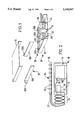
- FIG. 1 is an exploded schematic view of an apparatus for interconnecting optical fibres with tubing of the apparatus omitted;
- FIGS. 2 and 3 are respectively schematic side and top plan view of the apparatus of FIG. 1 in a contracted condition
- FIG. 4 is a schematic top plan view of part of the apparatus of FIG. 1;
- FIG. 5 is a schematic top plan view of an alternative apparatus.
- the apparatus 10 illustrated therein comprises a support 12, hereinafter referred to as a shelf, which supports means, generally referenced 14, for locating interconnections between optical fibres.
- the shelf 12 is slidably supported by a support means 16, hereinafter referred to as an intermediate shelf, for movement between a retracted position (FIG. 2) and an extended position relative to the intermediate shelf 16.
- the extended position provides access to the fibre interconnection locating means 14.
- the intermediate shelf 16 is itself slidably supported by a support means 18 which is mountable to a wall, rack or the like so as to extend substantially horizontally therefrom.
- the support means comprises two brackets 18A and 18B which in use are mounted by means of respective flanges 20A and 20B a predetermined distance apart to slidably support the intermediate shelf 16 for movement between a retracted position and an extended position in the same direction as the direction of sliding movement of the shelf 12.
- the components 12, 16 and 18 are provided with conventional slideways (not shown) to provide said sliding movement between the shelf 12 and intermediate shelf 16 and between the intermediate shelf 16 and the brackets 18.
- the apparatus when the apparatus is in a fully contracted condition with both the shelf and the intermediate shelf in their retracted positions, (i) the shelf 12 may be moved to its extended position, (ii) the intermediate shelf 16 may be moved to its extended position, and (iii) both the shelf and the intermediate shelf may be moved to their respective extended positions.
- the apparatus is mounted in vertical banks with similar apparatus and with optical fibres interconnected in the apparatus running up or down one or more usually both sides of these banks.
- movement of the shelf 12 to its extended position relative to the intermediate shelf 16 provides access to components on the shelf 12 and movement of the intermediate shelf 16 to its extended position relative to the brackets 18 provides access to components on the intermediate shelf from the front of the apparatus.
- each shelf 12 in a vertical bank of apparatus may be moved independently of the other shelves.
- each flexible tube 22 has a substantially helical configuration over at least a portion 24 of its extent which is located behind the shelf 12 for accommodating the sliding movement of the shelf between its retracted position (as illustrated in FIG. 2) and its extended position.
- the portion of helical configuration comprises a plurality of turns, but it is to be understood that this portion may comprise only one turn.
- Each flexible tube 22 is formed of a plastics or metal material and is preformed with its helically configured portion 24.
- the helically configured portion is able to stretch from its normal, unstressed condition which it adopts when the shelf 12 is in its retracted position, to accommodate movement of the shelf when the shelf is slid from its retracted position to its extended position, and to contract back to its normal position when the shelf 12 is slid back to its retracted position.
- the tube itself does not stretch or contract and the bend radii of the turns of the helical portion are arranged to be greater than the predetermined minimum bend radius of the optical fibre guided thereby.
- the wall thickness and/or configuration is such that there will be no damage to a fibre within the tube caused for example by kinking or other deformation during such movement.
- Each flexible tube 22 is connected with a respective further tube 26 located on the shelf and connected to the fibre interconnection location means 14. Connection between a tube 22 and a further tube 26 is via a connector means 28 on the shelf 12 which provides a releasable connection for at least one of the tubes 22, 26 so that each tube 22 may be selectively connected to any one of a plurality of tubes 26.
- the connector means comprises a plurality of connector devices or blocks 30, each of which provides a plurality of through-passages and means for connecting the tubes 22 and further tubes 26 to respective ends of the through passages.
- FIG. 2 illustrates the connection of one tube 22 to one tube 26 via a block 30 and a through-passage 32 therein.
- Each connector array 34 comprises a plurality of devices having through-passages 38 to the inner ends of which are connected respective tubes 22 and the outer ends of which are connectable to fibre ducting means (not shown), which may also comprise tubes, located to each side of the apparatus for ducting optical fibres to the apparatus.
- the tubes 22 are spaced apart behind the shelf 12 between the opposed sides 36, 37.
- a first group 40 of eight tubes is closer to the side 36 than the side 37 and a second group 42 of eight tubes is closer to the side 37 than the side 36.
- FIG. 1 A first group 40 of eight tubes is closer to the side 36 than the side 37 and a second group 42 of eight tubes is closer to the side 37 than the side 36.
- the interconnecting means 14 comprises two banks 44, 46 of housings 48, bank 44 being closer to side 36 than side 37 and bank 46 being closer to side 37 than side 36.
- the first group 40 of tubes 22 are connected to further tubes 26 connected to the bank 44 and the second group 42 of tubes are connected to further tubes connected to the bank 46.
- the tubes 22 are connected to the underside of connector blocks 30 and the tubes 26 to the uppersides thereof.
- Each bank 44, 46 has two associated connector blocks 30.
- these blocks are referenced 30A, B, C and D.
- Blocks 30A and B are connected to tubes 22 from group 40, block 30A being connected to tubes 22 in that group connected to the connector array on side 37 and block 30B being connected to the tubes 22 in the same group connected to the connection array on side 36.
- Blocks 30C and D on the other hand are connected to tubes 22 from group 42, block 30C being connected to the tubes 22 in that group connected to the connector array on side 37 and block 30D being connected to the connector array on side 36.
- bank 44 is shown arranged for connecting two optical fibres from side 37, which have been guided to block 30A, to two optical fibres from side 36, which have been guided to block 30B.
- each of the four through passages 32 in each block has a respective tube 22 connected to its lower end and each tube 26 may be connected to a selected one of the through-passages at its upper end to form a continuous passageway from one of the connector arrays to one of the banks.
- Each housing 48 in each bank thereof is adapted to locate at least one connection between two optical fibres guided thereto.
- Each housing also includes storage space for housing excess fibre length and is provided with path defining means for locating the fibres within the housing along paths which do not have bends with radii less than the predetermined minimum bend radius of the optical fibres.
- Each housing 48 in each bank 44, 46 is moveable out of alignment with the remainder of the housings in its bank in order to provide access to the or each optical fibre connection therein or the locations for such connections.
- each housing 48 is pivotably mounted with respect to the other housings in its bank about a respective vertical axis 50 indicated by reference 50 in FIG. 4.
- housings may be substantially the same as the housings for housing optical fibre connections disclosed in our co-pending UK Patent Application No. 9320101.0 to which attention is directed if further information is required.
- Each bank 44, 46 may have associated with it at least one housing accommodating a passive optical device and provided with connections for test purposes. In practice each such further housing would be provided in the in place of a housing 48.
- the second embodiment differs for the first embodiment in that the intermediate shelf 16, which slidably supports the shelf 12, is fixedly mounted to the wall, rack or the like, to which the support brackets 18 of the first embodiment are mounted, either directly or via mounting brackets. Since the intermediate shelf 16 itself is not slidably mounted, access to the connector arrays 34 would be limited if the connector arrays were mounted on the shelf extending in the direction of sliding movement as in the first embodiment.
- each connector array 34 is mounted to the intermediate shelf 16 or a part, such as a rack part, to which the intermediate shelf 16 is fixed, to extend in a direction which is transverse the direction of sliding movement.
- the connector arrays 34 are located to each side of the apparatus at the front thereof and are readily accessible.
- the tubes 22 are arranged in two groups 40, 42 as in the first embodiment and for the sake of clarity the tubes 22 connected to the connector array 34 to side 36 of the apparatus have been illustrated by broken lines.
- each of the disclosed apparatus enables optical fibres to each side of the apparatus to be interconnected in a managed way using the tubes 22 and 26 to guide the fibres to desired housings 48 for interconnection therein. It will also be understood that the use of connector blocks 30 for making connections between the tubes 22 and 26 provides for flexibility in the routing of fibres within the apparatus.
- the apparatus will be used for interconnecting an optical fibre running on one side of the apparatus to an optical fibre running on the other side thereof.
- the shelf 12 is moved to its extended position to provide access to the banks 44, 46 of housings 48
- the intermediate shelf 16 is moved to its extended position to provide access to the connector arrays 34.
- a particular housing 48 is selected for locating the connection and pivoted out of alignment with the other housings in its bank.
- a respective tube 22 extending from each of the connector arrays 34 is connected to a further tube extending from that housing. The fibres are then fed through the respective tubes 22 and further tubes connected thereto into the housing 48. If the intermediate shelf 16 is slidable, it is then slid back to its retracted position.
- the fibres are interconnected, typically by being fusion spliced together, and the interconnection and any excess fibre is located in the housing.
- the housing is pivoted back into alignment with the other housings in its bank and the shelf 12 slid back to its retracted position.
- an optical fibre assembly for blown installation comprising an optical fibre unit comprising at least one optical fibre is blown through a tube 22 and a further tube 26 connected thereto from the connector of the connector array 34 to which the tube 22 is connected directly into the housing 48 to which the further tube 26 is connected.
Landscapes
- Physics & Mathematics (AREA)
- General Physics & Mathematics (AREA)
- Optics & Photonics (AREA)
- Light Guides In General And Applications Therefor (AREA)
- Mechanical Coupling Of Light Guides (AREA)
Applications Claiming Priority (2)
| Application Number | Priority Date | Filing Date | Title |
|---|---|---|---|
| GB9412368A GB2291209B (en) | 1994-06-20 | 1994-06-20 | Optical fibre organiser having guiding tube for optical fibre |
| GB9412368 | 1994-06-20 |
Publications (1)
| Publication Number | Publication Date |
|---|---|
| US5550947A true US5550947A (en) | 1996-08-27 |
Family
ID=10757030
Family Applications (1)
| Application Number | Title | Priority Date | Filing Date |
|---|---|---|---|
| US08/464,296 Expired - Lifetime US5550947A (en) | 1994-06-20 | 1995-06-05 | Slidable optical fiber interconnecting tray with flexible fiber guiding tubes |
Country Status (10)
| Country | Link |
|---|---|
| US (1) | US5550947A (de) |
| EP (1) | EP0689074B1 (de) |
| AU (2) | AU679849B2 (de) |
| BR (1) | BR9502251A (de) |
| CA (1) | CA2152125C (de) |
| DE (1) | DE69527892T2 (de) |
| ES (1) | ES2181753T3 (de) |
| GB (2) | GB2291209B (de) |
| NZ (1) | NZ272348A (de) |
| ZA (1) | ZA955028B (de) |
Cited By (3)
| Publication number | Priority date | Publication date | Assignee | Title |
|---|---|---|---|---|
| US20050083201A1 (en) * | 1999-07-29 | 2005-04-21 | Trosper Scott T. | Radio frequency identification devices, remote communication devices, identification systems, communication methods, and identification methods |
| CN100420970C (zh) * | 2002-10-11 | 2008-09-24 | 3M创新有限公司 | 用于管理光导纤维的抽屉 |
| US20100290751A1 (en) * | 2005-02-16 | 2010-11-18 | Thierry Naudin | Modular cable head for optical networks |
Families Citing this family (2)
| Publication number | Priority date | Publication date | Assignee | Title |
|---|---|---|---|---|
| DE29721956U1 (de) * | 1997-12-12 | 1998-04-23 | BICC KWO Kabel GmbH, 12459 Berlin | Garnitur für Lichtwellenleiter-Kabel |
| JP4390705B2 (ja) | 2002-10-11 | 2009-12-24 | スリーエム イノベイティブ プロパティズ カンパニー | 光ファイバスプライシングカセットのアレイ |
Citations (20)
| Publication number | Priority date | Publication date | Assignee | Title |
|---|---|---|---|---|
| FR2515466A1 (fr) * | 1981-10-23 | 1983-04-29 | Lignes Telegraph Telephon | Dispositif de raccordement d'un cable de transmission, notamment d'un cable a fibres optiques, a des equipements electroniques |
| EP0211208A1 (de) * | 1985-07-30 | 1987-02-25 | Siemens Aktiengesellschaft | Verteiler für Lichtwellenleiter |
| FR2587127A1 (fr) * | 1985-09-06 | 1987-03-13 | Valleix Paul | Structure pour connexions optiques |
| US4717231A (en) * | 1983-01-05 | 1988-01-05 | Vincent Dewez | Interconnecting and distributing box for optical fibers |
| US4792203A (en) * | 1985-09-17 | 1988-12-20 | Adc Telecommunications, Inc. | Optical fiber distribution apparatus |
| EP0329935A2 (de) * | 1988-02-26 | 1989-08-30 | KABEL RHEYDT Aktiengesellschaft | Anordnung und Verfahren zum Bevorraten optischer Adern |
| EP0341027A2 (de) * | 1988-05-02 | 1989-11-08 | Gte Control Devices Of Puerto Rico Incorporated | Verteiler für optische Fasern |
| EP0356942A2 (de) * | 1988-08-29 | 1990-03-07 | Gte Control Devices Of Puerto Rico Incorporated | Verteilerconsole für Lichtwellenleiter |
| EP0408266A2 (de) * | 1989-07-11 | 1991-01-16 | BICC Public Limited Company | Abschlusssystem für optische Fasern |
| WO1991005281A1 (en) * | 1989-09-29 | 1991-04-18 | Northern Telecom Limited | Connector holders and distribution frame and connector holder assemblies for optical cable |
| US5067784A (en) * | 1990-11-19 | 1991-11-26 | George Debortoli | Connector holders |
| US5071211A (en) * | 1988-12-20 | 1991-12-10 | Northern Telecom Limited | Connector holders and distribution frame and connector holder assemblies for optical cable |
| EP0466668A2 (de) * | 1990-07-11 | 1992-01-15 | Adc Telecommunications, Inc. | Faseroptisches Steckermodul |
| US5093887A (en) * | 1990-09-28 | 1992-03-03 | Reliance Comm/Tec Corporation | Sliding cable tray with cable pivot arm |
| EP0477574A1 (de) * | 1990-09-25 | 1992-04-01 | Siemens Aktiengesellschaft | Verteilereinrichtung für Lichtwellenleiter |
| US5138688A (en) * | 1990-11-09 | 1992-08-11 | Northern Telecom Limited | Optical connector holder assembly |
| DE4107598A1 (de) * | 1991-03-09 | 1992-09-10 | Kromberg & Schubert | Optische wendelleitung |
| US5231687A (en) * | 1990-06-04 | 1993-07-27 | Bicc Plc | Termination system for optical fibres |
| US5339379A (en) * | 1993-06-18 | 1994-08-16 | Telect, Inc. | Telecommunication fiber optic cable distribution apparatus |
| US5353367A (en) * | 1993-11-29 | 1994-10-04 | Northern Telecom Limited | Distribution frame and optical connector holder combination |
Family Cites Families (2)
| Publication number | Priority date | Publication date | Assignee | Title |
|---|---|---|---|---|
| ATE134046T1 (de) | 1982-11-08 | 1996-02-15 | British Telecomm | Optisches kabel |
| US4648168A (en) * | 1983-12-19 | 1987-03-10 | N.V. Raychem S.A. | Optical fibre breakout |
-
1994
- 1994-06-20 GB GB9412368A patent/GB2291209B/en not_active Expired - Fee Related
- 1994-06-20 GB GB9713439A patent/GB2312969B/en not_active Expired - Lifetime
-
1995
- 1995-06-05 US US08/464,296 patent/US5550947A/en not_active Expired - Lifetime
- 1995-06-06 DE DE69527892T patent/DE69527892T2/de not_active Expired - Lifetime
- 1995-06-06 EP EP95303845A patent/EP0689074B1/de not_active Expired - Lifetime
- 1995-06-06 ES ES95303845T patent/ES2181753T3/es not_active Expired - Lifetime
- 1995-06-08 AU AU20597/95A patent/AU679849B2/en not_active Expired
- 1995-06-13 NZ NZ272348A patent/NZ272348A/en not_active IP Right Cessation
- 1995-06-19 CA CA002152125A patent/CA2152125C/en not_active Expired - Fee Related
- 1995-06-19 ZA ZA955028A patent/ZA955028B/xx unknown
- 1995-06-20 BR BR9502251A patent/BR9502251A/pt not_active IP Right Cessation
-
1997
- 1997-05-02 AU AU20084/97A patent/AU692732B2/en not_active Expired
Patent Citations (22)
| Publication number | Priority date | Publication date | Assignee | Title |
|---|---|---|---|---|
| FR2515466A1 (fr) * | 1981-10-23 | 1983-04-29 | Lignes Telegraph Telephon | Dispositif de raccordement d'un cable de transmission, notamment d'un cable a fibres optiques, a des equipements electroniques |
| US4717231A (en) * | 1983-01-05 | 1988-01-05 | Vincent Dewez | Interconnecting and distributing box for optical fibers |
| EP0211208A1 (de) * | 1985-07-30 | 1987-02-25 | Siemens Aktiengesellschaft | Verteiler für Lichtwellenleiter |
| US4765710A (en) * | 1985-07-30 | 1988-08-23 | Siemens Aktiengesellschaft | Distributing frame for optical waveguides and the like |
| FR2587127A1 (fr) * | 1985-09-06 | 1987-03-13 | Valleix Paul | Structure pour connexions optiques |
| US4776662A (en) * | 1985-09-06 | 1988-10-11 | Paul Valleix | Structure for optical connections |
| US4792203A (en) * | 1985-09-17 | 1988-12-20 | Adc Telecommunications, Inc. | Optical fiber distribution apparatus |
| EP0329935A2 (de) * | 1988-02-26 | 1989-08-30 | KABEL RHEYDT Aktiengesellschaft | Anordnung und Verfahren zum Bevorraten optischer Adern |
| EP0341027A2 (de) * | 1988-05-02 | 1989-11-08 | Gte Control Devices Of Puerto Rico Incorporated | Verteiler für optische Fasern |
| EP0356942A2 (de) * | 1988-08-29 | 1990-03-07 | Gte Control Devices Of Puerto Rico Incorporated | Verteilerconsole für Lichtwellenleiter |
| US5071211A (en) * | 1988-12-20 | 1991-12-10 | Northern Telecom Limited | Connector holders and distribution frame and connector holder assemblies for optical cable |
| EP0408266A2 (de) * | 1989-07-11 | 1991-01-16 | BICC Public Limited Company | Abschlusssystem für optische Fasern |
| WO1991005281A1 (en) * | 1989-09-29 | 1991-04-18 | Northern Telecom Limited | Connector holders and distribution frame and connector holder assemblies for optical cable |
| US5231687A (en) * | 1990-06-04 | 1993-07-27 | Bicc Plc | Termination system for optical fibres |
| EP0466668A2 (de) * | 1990-07-11 | 1992-01-15 | Adc Telecommunications, Inc. | Faseroptisches Steckermodul |
| EP0477574A1 (de) * | 1990-09-25 | 1992-04-01 | Siemens Aktiengesellschaft | Verteilereinrichtung für Lichtwellenleiter |
| US5093887A (en) * | 1990-09-28 | 1992-03-03 | Reliance Comm/Tec Corporation | Sliding cable tray with cable pivot arm |
| US5138688A (en) * | 1990-11-09 | 1992-08-11 | Northern Telecom Limited | Optical connector holder assembly |
| US5067784A (en) * | 1990-11-19 | 1991-11-26 | George Debortoli | Connector holders |
| DE4107598A1 (de) * | 1991-03-09 | 1992-09-10 | Kromberg & Schubert | Optische wendelleitung |
| US5339379A (en) * | 1993-06-18 | 1994-08-16 | Telect, Inc. | Telecommunication fiber optic cable distribution apparatus |
| US5353367A (en) * | 1993-11-29 | 1994-10-04 | Northern Telecom Limited | Distribution frame and optical connector holder combination |
Cited By (4)
| Publication number | Priority date | Publication date | Assignee | Title |
|---|---|---|---|---|
| US20050083201A1 (en) * | 1999-07-29 | 2005-04-21 | Trosper Scott T. | Radio frequency identification devices, remote communication devices, identification systems, communication methods, and identification methods |
| CN100420970C (zh) * | 2002-10-11 | 2008-09-24 | 3M创新有限公司 | 用于管理光导纤维的抽屉 |
| US20100290751A1 (en) * | 2005-02-16 | 2010-11-18 | Thierry Naudin | Modular cable head for optical networks |
| US7986864B2 (en) | 2005-02-16 | 2011-07-26 | 3M Innovative Properties Company | Modular cable head for optical networks |
Also Published As
| Publication number | Publication date |
|---|---|
| GB2312969A (en) | 1997-11-12 |
| EP0689074A1 (de) | 1995-12-27 |
| GB2312969A8 (en) | 1998-02-05 |
| GB2291209A (en) | 1996-01-17 |
| GB9412368D0 (en) | 1994-08-10 |
| BR9502251A (pt) | 1996-01-23 |
| AU692732B2 (en) | 1998-06-11 |
| NZ272348A (en) | 1997-01-29 |
| ZA955028B (en) | 1996-02-08 |
| CA2152125A1 (en) | 1995-12-21 |
| AU2008497A (en) | 1997-07-10 |
| EP0689074B1 (de) | 2002-08-28 |
| GB2291209B (en) | 1998-04-01 |
| ES2181753T3 (es) | 2003-03-01 |
| GB2312969B (en) | 1998-04-01 |
| AU679849B2 (en) | 1997-07-10 |
| AU2059795A (en) | 1996-01-04 |
| CA2152125C (en) | 1997-11-18 |
| GB9713439D0 (en) | 1997-08-27 |
| DE69527892T2 (de) | 2003-05-28 |
| DE69527892D1 (de) | 2002-10-02 |
Similar Documents
| Publication | Publication Date | Title |
|---|---|---|
| US5640481A (en) | Guiding optical fibres | |
| US6788871B2 (en) | Optical fiber connection housing with an outlet connector element and a splice connection to an optical line group | |
| EP1325371B1 (de) | Faserverteiler-halterungssystem mit hoher dichte | |
| EP1549982B1 (de) | Schublade zur handhabung von optischen fasern | |
| US4898448A (en) | Fiber distribution panel | |
| US7460758B2 (en) | Fiber management system | |
| US20100278499A1 (en) | Fiber Optic Panels Configured to Retain Fiber Optic Components in a Depth Space of a Chassis | |
| US6445865B1 (en) | Optical fiber jumper cable bend limiter and housing therefor | |
| NO320681B1 (no) | Sentral for fordeling av fiberoptiske linjer | |
| US7382961B2 (en) | Fiber transitioning | |
| US5550947A (en) | Slidable optical fiber interconnecting tray with flexible fiber guiding tubes | |
| CN1133643A (zh) | 光纤编排器 | |
| WO2001035142A1 (en) | Optical fibre management | |
| US6839498B2 (en) | Optical fiber cable swivel for fiber optic distribution frames | |
| US20160216471A1 (en) | Fiber optic assemblies with a fiber optic cable movable between cable openings | |
| US20200028339A1 (en) | Flexible Conduit Systems For Routing Cables | |
| WO1999047960A1 (en) | Optical fibre overlength storage | |
| EP2833180A1 (de) | Kabelführungselement für optische Fasern | |
| WO2006059070A1 (en) | Improvements in or relating to optical fibre distribution apparatus |
Legal Events
| Date | Code | Title | Description |
|---|---|---|---|
| AS | Assignment |
Owner name: PIRELLI GENERAL PLC, UNITED KINGDOM Free format text: ASSIGNMENT OF ASSIGNORS INTEREST;ASSIGNORS:LLEWELLYN, LAURENCE;GRAVESTON, MARK GEORGE;KANDASAMY, ISPRAN SHARMA;AND OTHERS;REEL/FRAME:007612/0670;SIGNING DATES FROM 19950607 TO 19950611 |
|
| STCF | Information on status: patent grant |
Free format text: PATENTED CASE |
|
| FEPP | Fee payment procedure |
Free format text: PAYOR NUMBER ASSIGNED (ORIGINAL EVENT CODE: ASPN); ENTITY STATUS OF PATENT OWNER: LARGE ENTITY |
|
| FPAY | Fee payment |
Year of fee payment: 4 |
|
| FPAY | Fee payment |
Year of fee payment: 8 |
|
| REMI | Maintenance fee reminder mailed | ||
| FPAY | Fee payment |
Year of fee payment: 12 |
|
| REMI | Maintenance fee reminder mailed | ||
| AS | Assignment |
Owner name: PRYSMIAN CABLES & SYSTEMS LIMITED, ENGLAND Free format text: CHANGE OF NAME;ASSIGNOR:PIRELLI GENERAL PLC;REEL/FRAME:022846/0567 Effective date: 20051003 |