EP0688981B1 - Ensemble de vis d'ajustage pour une cupule d'articulation dans un moteur à combustion interne - Google Patents
Ensemble de vis d'ajustage pour une cupule d'articulation dans un moteur à combustion interne Download PDFInfo
- Publication number
- EP0688981B1 EP0688981B1 EP95109163A EP95109163A EP0688981B1 EP 0688981 B1 EP0688981 B1 EP 0688981B1 EP 95109163 A EP95109163 A EP 95109163A EP 95109163 A EP95109163 A EP 95109163A EP 0688981 B1 EP0688981 B1 EP 0688981B1
- Authority
- EP
- European Patent Office
- Prior art keywords
- element means
- screw
- adjusting screw
- screw assembly
- internal combustion
- Prior art date
- Legal status (The legal status is an assumption and is not a legal conclusion. Google has not performed a legal analysis and makes no representation as to the accuracy of the status listed.)
- Expired - Lifetime
Links
- 238000002485 combustion reaction Methods 0.000 title claims description 29
- 235000006146 Dioscorea elephantipes Nutrition 0.000 title description 8
- 241001302002 Dioscorea elephantipes Species 0.000 title 1
- 239000000919 ceramic Substances 0.000 claims description 30
- 230000033001 locomotion Effects 0.000 claims description 24
- 229910052751 metal Inorganic materials 0.000 claims description 23
- 239000002184 metal Substances 0.000 claims description 21
- 239000000446 fuel Substances 0.000 claims description 19
- 229910052581 Si3N4 Inorganic materials 0.000 claims description 6
- HQVNEWCFYHHQES-UHFFFAOYSA-N silicon nitride Chemical compound N12[Si]34N5[Si]62N3[Si]51N64 HQVNEWCFYHHQES-UHFFFAOYSA-N 0.000 claims description 6
- 229910000831 Steel Inorganic materials 0.000 claims description 3
- 239000010959 steel Substances 0.000 claims description 3
- 229910000639 Spring steel Inorganic materials 0.000 claims description 2
- 239000002905 metal composite material Substances 0.000 description 8
- 244000110343 Elephantopus scaber Species 0.000 description 7
- 230000000712 assembly Effects 0.000 description 5
- 238000000429 assembly Methods 0.000 description 5
- 239000002131 composite material Substances 0.000 description 5
- 230000008878 coupling Effects 0.000 description 4
- 238000010168 coupling process Methods 0.000 description 4
- 238000005859 coupling reaction Methods 0.000 description 4
- 229910010293 ceramic material Inorganic materials 0.000 description 3
- 238000000227 grinding Methods 0.000 description 3
- 230000020169 heat generation Effects 0.000 description 3
- 238000005461 lubrication Methods 0.000 description 3
- 150000002739 metals Chemical class 0.000 description 3
- 238000005498 polishing Methods 0.000 description 3
- MCMNRKCIXSYSNV-UHFFFAOYSA-N Zirconium dioxide Chemical compound O=[Zr]=O MCMNRKCIXSYSNV-UHFFFAOYSA-N 0.000 description 2
- 230000006835 compression Effects 0.000 description 2
- 238000007906 compression Methods 0.000 description 2
- 230000006866 deterioration Effects 0.000 description 2
- 239000000463 material Substances 0.000 description 2
- 230000003071 parasitic effect Effects 0.000 description 2
- PNEYBMLMFCGWSK-UHFFFAOYSA-N Alumina Chemical class [O-2].[O-2].[O-2].[Al+3].[Al+3] PNEYBMLMFCGWSK-UHFFFAOYSA-N 0.000 description 1
- 244000304337 Cuminum cyminum Species 0.000 description 1
- 230000005540 biological transmission Effects 0.000 description 1
- 238000005266 casting Methods 0.000 description 1
- 238000010276 construction Methods 0.000 description 1
- 238000001816 cooling Methods 0.000 description 1
- 239000002537 cosmetic Substances 0.000 description 1
- 238000005304 joining Methods 0.000 description 1
- 238000009533 lab test Methods 0.000 description 1
- 238000004519 manufacturing process Methods 0.000 description 1
- 239000007769 metal material Substances 0.000 description 1
- 238000000034 method Methods 0.000 description 1
- SIWVEOZUMHYXCS-UHFFFAOYSA-N oxo(oxoyttriooxy)yttrium Chemical compound O=[Y]O[Y]=O SIWVEOZUMHYXCS-UHFFFAOYSA-N 0.000 description 1
- 239000000843 powder Substances 0.000 description 1
- 229910052761 rare earth metal Inorganic materials 0.000 description 1
- 150000002910 rare earth metals Chemical class 0.000 description 1
- 230000000717 retained effect Effects 0.000 description 1
- HBMJWWWQQXIZIP-UHFFFAOYSA-N silicon carbide Chemical compound [Si+]#[C-] HBMJWWWQQXIZIP-UHFFFAOYSA-N 0.000 description 1
- 229910010271 silicon carbide Inorganic materials 0.000 description 1
Images
Classifications
-
- F—MECHANICAL ENGINEERING; LIGHTING; HEATING; WEAPONS; BLASTING
- F01—MACHINES OR ENGINES IN GENERAL; ENGINE PLANTS IN GENERAL; STEAM ENGINES
- F01L—CYCLICALLY OPERATING VALVES FOR MACHINES OR ENGINES
- F01L1/00—Valve-gear or valve arrangements, e.g. lift-valve gear
- F01L1/20—Adjusting or compensating clearance
-
- F—MECHANICAL ENGINEERING; LIGHTING; HEATING; WEAPONS; BLASTING
- F01—MACHINES OR ENGINES IN GENERAL; ENGINE PLANTS IN GENERAL; STEAM ENGINES
- F01L—CYCLICALLY OPERATING VALVES FOR MACHINES OR ENGINES
- F01L1/00—Valve-gear or valve arrangements, e.g. lift-valve gear
- F01L1/12—Transmitting gear between valve drive and valve
- F01L1/14—Tappets; Push rods
- F01L1/146—Push-rods
-
- F—MECHANICAL ENGINEERING; LIGHTING; HEATING; WEAPONS; BLASTING
- F01—MACHINES OR ENGINES IN GENERAL; ENGINE PLANTS IN GENERAL; STEAM ENGINES
- F01L—CYCLICALLY OPERATING VALVES FOR MACHINES OR ENGINES
- F01L2301/00—Using particular materials
- F01L2301/02—Using ceramic materials
-
- F—MECHANICAL ENGINEERING; LIGHTING; HEATING; WEAPONS; BLASTING
- F02—COMBUSTION ENGINES; HOT-GAS OR COMBUSTION-PRODUCT ENGINE PLANTS
- F02B—INTERNAL-COMBUSTION PISTON ENGINES; COMBUSTION ENGINES IN GENERAL
- F02B3/00—Engines characterised by air compression and subsequent fuel addition
- F02B3/06—Engines characterised by air compression and subsequent fuel addition with compression ignition
-
- Y—GENERAL TAGGING OF NEW TECHNOLOGICAL DEVELOPMENTS; GENERAL TAGGING OF CROSS-SECTIONAL TECHNOLOGIES SPANNING OVER SEVERAL SECTIONS OF THE IPC; TECHNICAL SUBJECTS COVERED BY FORMER USPC CROSS-REFERENCE ART COLLECTIONS [XRACs] AND DIGESTS
- Y10—TECHNICAL SUBJECTS COVERED BY FORMER USPC
- Y10T—TECHNICAL SUBJECTS COVERED BY FORMER US CLASSIFICATION
- Y10T74/00—Machine element or mechanism
- Y10T74/21—Elements
- Y10T74/2142—Pitmans and connecting rods
- Y10T74/2151—Longitudinally adjustable
Definitions
- the present invention relates generally to contact interfaces between mechanically driven actuating and actuated members in internal combustion engines and specifically to an assembly for a contact interface between an actuating member and an actuated member of an internal combustion engine that minimizes sliding friction and wear at the interface.
- U.S. Patent No. 4,833,977 to Haahtela discloses a ceramic piston ring carrier held in place on a metal piston by casting in or with a locking ring to improve force transmission and frictional conditions between the piston and the cylinder.
- U.S. Patent No. 4,848,286 to Bentz assigned to Cummins Engine Co., the assignee of the present invention, discloses the use of an external metal connector for joining ceramic and metal components of a pivot rod.
- U.S. Patent No. 4,966108 to Bentz et al. and commonly owned by the assignee of the present application discloses an internal combustion engine ball and socket joint assembly that includes an interface which is subject to high contact stresses, particularly those produced by highly loaded sliding contact.
- One of the joint components is formed of a metallic material, and the other component is formed of a high density ceramic material.
- the ceramic material is sintered and may include rare earth metals such as yttrium oxide or may include aluminum oxides. This construction is capable of withstanding the compressive loads experienced by an internal combustion engine ball and socket joint. However, sliding wear and sliding friction are not typically encountered in this type of joint.
- U.S. Patent No. 5,279,211 to Bentz et al. also owned by the assignee of the present invention, describes a wear-resistant metal and ceramic composite capable of withstanding the stresses produced in the interface in mechanically actuated internal combustion components such as a compression brake master piston or hydraulic tappet cam follower.
- the retainer structure used to hold the ceramic and metal components together in this composite securely retains the ceramic pad within the metal in a manner which prohibits relative movement between the metal and the ceramic.
- Some internal combustion engine actuator components particularly components of the "elephant's foot" type designed for use in valves, valve crossheads and fuel injectors, require rotatably unconstrained attachments between actuator elements to allow them to function effectively. Therefore, the arrangement described in Patent Nos. 4,966,108 and 5,279,211 is not applicable to such components.
- Actuated members such as engine valves, valve crossheads and unit type fuel injectors contact actuating members thousands of times each minute during engine operation.
- the adjusting screw assemblies associated with these interfaces tend to produce undesirable sliding friction and sliding wear at the actuated member interface, which ultimately interferes with the proper functioning of the adjusting screw assembly.
- U.S. Patent No. 5,195,489 to Reich discloses a link structure for an internal combustion engine which comprises providing a convex shape to one end of a compression release engine retarder push rod associated with a master or slave piston, while the interfacing surface of the piston is flat so that the convex end rolls rather than slides.
- This arrangement may minimize the need for grinding or polishing the surfaces or the need for lubrication at the interface.
- any of the interfacing structures could be formed of a structural ceramic to address problems arising from wear and heat generation by friction at the interfacing surfaces.
- the sliding friction loss between the rocker levers and valve crossheads in a heavy duty diesel engine can be 0.5 HP (horsepower). This loss, which is equivalent to a reduction in brake specific fuel consumption (b.s.f.c.) of 0.2%, generates heat that must be removed by the engine's cooling system. Friction forces generated in the type of sliding contact that occurs between a rocker lever and valve crosshead are transferred to the adjacent valve components. This produces additional sliding friction, wear and component failure.
- Sliding wear can produce a range of problems from cosmetic surface deterioration to loss of mechanical set or calibration to the increased likelihood of catastrophic failure of the worn component, which prior art ceramic and metal composite structures available for internal combustion engines have not solved.
- the prior art therefore, has failed to provide a ceramic-metal composite for an internal combustion engine component which provides a loose attachment of the ceramic element to the metal element in a way that permits rotatably unconstrained movement between the ceramic and metal elements and substantially reduces sliding wear and sliding friction.
- a sliding wear-resistant adjusting screw assembly for an actuator member in an internal combustion engine intended to contact an actuated member, such as an engine valve, valve crosshead or unit type fuel injector at an interface.
- the adjusting screw assembly includes a metal screw element and a ceramic pad element.
- the metal element and the ceramic element are complimentary configured and held together by a retaining element that permits relative movement between the metal and ceramic elements at the metal-ceramic joint. This arrangement avoids the sliding friction losses and sliding wear losses which are common with adjusting screw assemblies presently used in connection with internal combustion engine actuating members.
- the present invention addresses the problems related to sliding friction and wear in a variety of internal combustion engine applications, including valve crossheads and unit fuel injectors by cost effectively incorporating an advanced structural ceramic element in the kind of adjusting screw assembly known as an "elephant's foot" or swivel pad adjusting screw assembly.
- Structural ceramics particularly silicon nitride, have consistently been demonstrated in both laboratory tests and in a broad range of commercial applications to provide superior wear and friction performance compared to metals.
- the present invention offers substantial economic and performance advantages over commercially available adjusting screw assemblies made entirely of metal.
- Adjusting screws are usually used in internal combustion engines where it is necessary to adjust the stroke of an engine actuating component, such as, for example, a valve crosshead or unit fuel injector plunger.
- an engine actuating component such as, for example, a valve crosshead or unit fuel injector plunger.
- the motion of link structures associated with these components requires relative movement between interfacing surfaces of the adjusting screw elements to transmit actuating movement to the engine actuating component.
- the metal structures customarily used to form these elements required grinding and polishing, as well as proper lubrication, to allow the elements to function and to minimize wear.
- the elephant's foot or swivel pad adjusting screw assembly of the present invention minimizes expensive ceramic grinding and polishing manufacturing operations and application lubrication requirements.
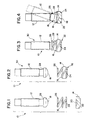
- Figures 1-4 illustrate the adjusting screw assembly of the present invention in various stages of assembly.
- FIG. 1 shows the component parts of the adjusting screw assembly of the present invention completed unassembled.
- the complete assembly 10 includes three elements: a screw member 12, an integral wear-resistant slider pad and socket 14 and a retainer element 16.
- the screw element 12 is preferably formed from steel that has been threaded, heat treated and tumbled. The material removal operations typically performed on steel internal combustion engine components are not required with the design of the present invention.
- the screw element 12 includes a rounded terminus or ball portion 18 which has an offset radius design to achieve annular contact in a spherical socket 20 in the pad element 14.
- the pad element 14 is made from a ceramic material, preferably silicon nitride. Silicon nitride powders are die pressed and pressureless sintered to produce the configuration shown in the drawings.
- the shallow spherical socket 20 receives the ball portion 18 of the screw element 12.
- the sintered ceramic pad 14 is preferably tumbled to break any sharp edges and improve the surface finish of the ceramic.
- the retainer element 16 is preferably made of spring steel wire. Conventional "wound on mandrel" processes and tooling may be used to form the retainer element.
- the retainer element 16 securely captures the ceramic pad 14, which includes an annular ledge 22 to engage one end 24 of the retainer element 16.
- the screw element 12 is loosely attached to the pad 14 by the other end 26 of the retainer element 16.
- the screw element also includes an annular ledge 28, which is significantly larger in diameter than the diameter of the screw element. The end 26 of the retainer element 16 is retained on the screw element slightly above the annular ledge 28.
- the final adjusting screw assembly which is shown completely assembled in Figures 3 and 4, consists of only two subassemblies, which are shown in Figure 2: the screw 30 and pad/retainer subassembly 32.
- Figure 4 shows, in dashed lines, the relative movement of the ball portion 18 of the screw element 12 in the socket 20 of the pad 14.
- the retainer element 16 will experience little, if any, dynamic loading because of its design. Therefore, the retainer 16 is a nonparticipating member in situations when lash between the adjusting screw assembly 10 and the engine actuated member is insufficient to allow an unretained pad to escape.
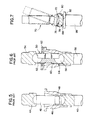
- Figure 7 illustrates one application of the adjusting screw assembly of the present invention in a link for transmitting movement to an engine actuation member, a unit fuel injector.
- Figures 5 and 6 illustrate two different prior art injector actuator links, also in a unit fuel injector.
- Figure 5 shows a link conventionally used to transmit reciprocal movement to the plunger 40 of a unit fuel injector (not shown).
- a link 42 engages a socket 44 of a connecting rod (not shown) or similar structure.
- a coupling structure 46 and a retainer 48 hold the link in place as it reciprocates with the plunger 40.
- Figure 6 illustrates a ball link 50 that can be used for the same purpose.
- a first ball 52 at one end of the link 50 engages a socket 54, and a second ball 56 at the opposite end of the link 50 engages the fuel injector plunger 58.
- This arrangement also requires a coupling 60.
- a link retainer 62 is required to retain the link 50 in the coupling 60.
- a ball retainer 64 is also needed to maintain the balls 52 and 56 in their proper positions.
- the adjusting screw assembly 70 of the present invention does not require a coupling structure, and needs only one simple retainer element 72 both to hold the assembly together and to permit the movement required to effectively transmit arcuate motion to the reciprocal motion required to actuate the fuel injector.
- the screw element ball portion 76 can move freely in the socket 78 of the ceramic pad 80 without the sliding wear and friction problems of the prior art.
- the contact surface 82 of the pad 80 does not require a specially machined socket, but contacts a flat surface 84 on the fuel injector plunger 86 to actuate the injector. This arrangement substantially eliminates the parasitic loss, heat generation and frictional forces associated with sliding friction in the currently available all metal adjusting screw assemblies.
- the elephant's foot or swivel pad adjusting screw of the present invention will find its primary application in association with actuated members such as valves, valve crossheads and unit fuel injectors in an internal combustion engine, particularly a diesel engine.
- actuated members such as valves, valve crossheads and unit fuel injectors in an internal combustion engine, particularly a diesel engine.
- the design of this assembly will be useful in any system wherein reciprocating motion is coupled to arcuate motion to avoid the problems accompanying sliding wear, including surface deterioration, loss of mechanical set or calibration and component failure.
Landscapes
- Engineering & Computer Science (AREA)
- Mechanical Engineering (AREA)
- General Engineering & Computer Science (AREA)
- Valve-Gear Or Valve Arrangements (AREA)
- Fuel-Injection Apparatus (AREA)
Claims (6)
- Assemblage de vis de réglage (10; 70) résistant à la friction et à l'usure par glissement conçu pour transmettre un mouvement le long d'une voie arquée au mouvement alternatif requis pour la commande d'un élément (86) d'entraínement d'un moteur à combustion interne, ledit assemblage de vis de réglage (10; 70) comprenant:a) un moyen d'élément de vis (30) qui est réalisé en métal et qui englobe une face de contact arquée (18; 76);b) un moyen d'élément de coussin de rembourrage (14; 80) qui est réalisé en une matière céramique de structure et qui englobe, dans une surface, un moyen de creux (20; 78) configuré pour recevoir ladite face de contact arquée (18; 76) dudit élément de vis, et sur une surface opposée, un moyen de contact plane (82) pour former une interface avec ledit élément d'entraínement de moteur (86); etc) un moyen d'élément de retenue (16; 72) pour maintenir fermement, mais avec du jeu, ledit moyen d'élément de coussin de rembourrage (14; 80) contre ledit moyen d'élément de vis (30) pour permettre un mouvement arqué dudit moyen d'élément de vis (30) par rapport audit moyen d'élément de coussin de rembourrage (14; 80), ledit moyen d'élément de retenue (16; 72) possédant une configuration essentiellement hélicoïdale dans laquelle une extrémité (26) dudit moyen d'élément de retenue (16; 72) entre en contact avec une section à gradin annulaire (28) dudit moyen d'élément de vis (30) et l'autre extrémité (24) dudit moyen d'élément de retenue (16; 72) entre en contact avec un épaulement annulaire (22) dudit moyen d'élément de coussin de rembourrage (14; 80).
- Assemblage de vis selon la revendication 1, caractérisé en ce que ledit moyen d'élément de vis (30) est réalisé en acier et ledit moyen d'élément de coussin de rembourrage (14; 80) est réalisé en nitrure de silicium, et de préférence ledit moyen d'élément de retenue (16; 72) est réalisé en acier à ressort.
- Assemblage de vis selon l'une quelconque des revendications précédentes, caractérisé en ce que ledit moyen d'élément de vis (30) englobe une portion de corps axial possédant un diamètre axial constant et une portion de base terminale, le diamètre de ladite section à gradin annulaire (28) étant supérieur à celui de ladite portion de corps axial entre ladite portion de corps axial et ladite face de contact arquée (18; 76).
- Assemblage de vis selon l'une quelconque des revendications précédentes, caractérisé en ce que ledit moyen d'élément de coussin de rembourrage (14; 80) possède une portion à plus grand diamètre contenant ledit moyen de creux (20; 78) et une portion à plus petit diamètre englobant ladite face de contact plane (82), ledit épaulement annulaire (22) étant disposé entre elles.
- Assemblage de vis selon l'une quelconque des revendications précédentes, caractérisé en ce que ladite face de contact arquée (18; 76) possède essentiellement le même rayon de courbure que celui dudit moyen de creux (20; 78).
- Assemblage de bielle coulissante pour un moteur à combustion interne destiné à entraíner un injecteur de carburant unitaire en transmettant le mouvement arqué transmis à l'assemblage de bielle coulissante au mouvement réciproque requis pour entraíner l'injecteur de carburant unitaire, dans lequel ledit assemblage de bielle coulissante englobe un assemblage de vis de réglage (10; 70) selon l'une quelconque des revendications précédentes.
Applications Claiming Priority (2)
| Application Number | Priority Date | Filing Date | Title |
|---|---|---|---|
| US08/263,232 US5542315A (en) | 1994-06-21 | 1994-06-21 | Elephant's foot adjusting screw assembly for internal combustion engine |
| US263232 | 1994-06-21 |
Publications (2)
| Publication Number | Publication Date |
|---|---|
| EP0688981A1 EP0688981A1 (fr) | 1995-12-27 |
| EP0688981B1 true EP0688981B1 (fr) | 1999-08-18 |
Family
ID=23000919
Family Applications (1)
| Application Number | Title | Priority Date | Filing Date |
|---|---|---|---|
| EP95109163A Expired - Lifetime EP0688981B1 (fr) | 1994-06-21 | 1995-06-14 | Ensemble de vis d'ajustage pour une cupule d'articulation dans un moteur à combustion interne |
Country Status (4)
| Country | Link |
|---|---|
| US (1) | US5542315A (fr) |
| EP (1) | EP0688981B1 (fr) |
| JP (1) | JP2776460B2 (fr) |
| DE (1) | DE69511475T2 (fr) |
Families Citing this family (9)
| Publication number | Priority date | Publication date | Assignee | Title |
|---|---|---|---|---|
| US5645023A (en) * | 1996-04-08 | 1997-07-08 | Chrysler Corporation | Valve train for an internal combustion engine |
| US5669344A (en) * | 1996-08-09 | 1997-09-23 | Chrysler Corporation | Sohc system with radial valves |
| DE19750806B4 (de) * | 1997-11-17 | 2015-03-26 | Schaeffler Technologies AG & Co. KG | Hydraulische Spielausgleichsvorrichtung |
| US6349689B1 (en) | 2000-04-18 | 2002-02-26 | Cummins Inc. | Tappet assembly with a ceramic wear pad |
| US6557507B2 (en) | 2001-03-30 | 2003-05-06 | Caterpillar Inc. | Rocker arm assembly |
| JP4143031B2 (ja) * | 2003-12-26 | 2008-09-03 | 本田技研工業株式会社 | 内燃機関の動弁系のタペット機構 |
| US20050183684A1 (en) * | 2004-02-25 | 2005-08-25 | James Strepek | Valve operating system in an internal combustion engine |
| US7789052B2 (en) * | 2007-06-29 | 2010-09-07 | Caterpillar Inc. | Variable valve actuator having self-centering pivotal piston |
| US20110253088A1 (en) * | 2010-04-15 | 2011-10-20 | Schaeffler Technologies Gmbh & Co. Kg | Structural unit for a gas exchange valve train of an internal combustion engine |
Family Cites Families (13)
| Publication number | Priority date | Publication date | Assignee | Title |
|---|---|---|---|---|
| US3101402A (en) * | 1960-02-12 | 1963-08-20 | Bundy Tubing Co | Push rod structure and method of manufacture |
| EP0133192A1 (fr) * | 1983-08-05 | 1985-02-20 | Chrysler Corporation | Poussoir avec face de came céramique pour moteur et son procédé de magnéto-formage |
| US4833977A (en) * | 1986-05-07 | 1989-05-30 | Volkswagen Ag | Piston for internal combustion engine |
| DE3725245A1 (de) * | 1987-07-30 | 1989-02-09 | Schaeffler Waelzlager Kg | Kugelgelenk, welches zwischen einen kipphebel und einen ventilschaft eines verbrennungsmotors eingeschaltet ist |
| JPH029044U (fr) * | 1988-07-02 | 1990-01-22 | ||
| US4864983A (en) * | 1988-08-17 | 1989-09-12 | Caterpillar Inc. | Pushrod retainer |
| US4848286A (en) * | 1988-09-28 | 1989-07-18 | Cummins Engine Company, Inc. | Ceramic tiped pivot rod and method for its manufacture |
| JPH0276101U (fr) * | 1988-11-29 | 1990-06-11 | ||
| US4966108A (en) * | 1989-04-28 | 1990-10-30 | Cummins Engine Company, Inc. | Sintered ceramic ball and socket joint assembly |
| US5083884A (en) * | 1990-05-01 | 1992-01-28 | Norton Company | Metal ceramic composite body |
| US5195489A (en) * | 1992-01-03 | 1993-03-23 | Jacobs Brake Technology Corporation | Push rods for pistons in compression release engine retarders |
| US5279211A (en) * | 1992-04-24 | 1994-01-18 | Cummins Engine Company, Inc. | Mechanically retained wear-resistant ceramic pad |
| JPH063171A (ja) * | 1992-06-17 | 1994-01-11 | Fuji Electric Co Ltd | 流体振動検出装置 |
-
1994
- 1994-06-21 US US08/263,232 patent/US5542315A/en not_active Expired - Fee Related
-
1995
- 1995-06-14 EP EP95109163A patent/EP0688981B1/fr not_active Expired - Lifetime
- 1995-06-14 DE DE69511475T patent/DE69511475T2/de not_active Expired - Fee Related
- 1995-06-21 JP JP7155017A patent/JP2776460B2/ja not_active Expired - Fee Related
Also Published As
| Publication number | Publication date |
|---|---|
| US5542315A (en) | 1996-08-06 |
| EP0688981A1 (fr) | 1995-12-27 |
| DE69511475D1 (de) | 1999-09-23 |
| JPH08170508A (ja) | 1996-07-02 |
| DE69511475T2 (de) | 1999-12-16 |
| JP2776460B2 (ja) | 1998-07-16 |
Similar Documents
| Publication | Publication Date | Title |
|---|---|---|
| US5775203A (en) | High pressure fuel pump assembly | |
| EP0688981B1 (fr) | Ensemble de vis d'ajustage pour une cupule d'articulation dans un moteur à combustion interne | |
| US7207303B2 (en) | Switching element | |
| EP0282714B1 (fr) | Tige-poussoir avec pivots en céramique et son procédé de fabrication | |
| US5060607A (en) | Tappet structure | |
| EP0552596B1 (fr) | Tiges poussoirs pour pistons de dispositifs de freinage pour moteur par décompression | |
| US5279211A (en) | Mechanically retained wear-resistant ceramic pad | |
| US5168841A (en) | Tappet with ceramic seat plate | |
| US5740788A (en) | Fiber reinforced ceramic matrix composite piston and cylinder/sleeve for an internal combustion engine | |
| GB2281601A (en) | A cam shaft and composite cam with outer surfaces impregnated with a solid lubricant | |
| US4777844A (en) | Hybrid ceramic/metal compression link for use in higher temperature applications | |
| WO2010008785A2 (fr) | Axe de piston, bielle, piston et ensemble de piston les comprenant, et procédé de construction et d’assemblage associés | |
| US4966108A (en) | Sintered ceramic ball and socket joint assembly | |
| US5410995A (en) | Valve crosshead assembly with wear-reducing contact pad | |
| US3501180A (en) | Coupling to provide angular and lateral orientation | |
| CN110821667B (zh) | 具有用于调节有效连杆长度的偏心轮调节装置的连杆 | |
| US5327814A (en) | Mechanical assemblies and methods of making same | |
| US5361740A (en) | Mechanical assemblies with hardened bearing surfaces | |
| US5572963A (en) | Hydraulic tappet | |
| US5809842A (en) | Ceramic sliding component | |
| JP3565746B2 (ja) | 流体ポンプ | |
| JPH09166003A (ja) | 内燃機関用タペット及びその製造方法 | |
| JPH07102913A (ja) | ローラー | |
| JP2660578B2 (ja) | 摺動部品 | |
| JPH0826838A (ja) | セラミックス−金属複合体 |
Legal Events
| Date | Code | Title | Description |
|---|---|---|---|
| PUAI | Public reference made under article 153(3) epc to a published international application that has entered the european phase |
Free format text: ORIGINAL CODE: 0009012 |
|
| AK | Designated contracting states |
Kind code of ref document: A1 Designated state(s): DE GB |
|
| 17P | Request for examination filed |
Effective date: 19960523 |
|
| 17Q | First examination report despatched |
Effective date: 19980202 |
|
| GRAG | Despatch of communication of intention to grant |
Free format text: ORIGINAL CODE: EPIDOS AGRA |
|
| GRAG | Despatch of communication of intention to grant |
Free format text: ORIGINAL CODE: EPIDOS AGRA |
|
| GRAH | Despatch of communication of intention to grant a patent |
Free format text: ORIGINAL CODE: EPIDOS IGRA |
|
| GRAH | Despatch of communication of intention to grant a patent |
Free format text: ORIGINAL CODE: EPIDOS IGRA |
|
| GRAA | (expected) grant |
Free format text: ORIGINAL CODE: 0009210 |
|
| AK | Designated contracting states |
Kind code of ref document: B1 Designated state(s): DE GB |
|
| RIN1 | Information on inventor provided before grant (corrected) |
Inventor name: GENTER,DAVID P Inventor name: BENTZ,JOSEPH C Inventor name: CARROLL,JOHN T III |
|
| REF | Corresponds to: |
Ref document number: 69511475 Country of ref document: DE Date of ref document: 19990923 |
|
| PLBE | No opposition filed within time limit |
Free format text: ORIGINAL CODE: 0009261 |
|
| STAA | Information on the status of an ep patent application or granted ep patent |
Free format text: STATUS: NO OPPOSITION FILED WITHIN TIME LIMIT |
|
| 26N | No opposition filed | ||
| REG | Reference to a national code |
Ref country code: GB Ref legal event code: IF02 |
|
| PGFP | Annual fee paid to national office [announced via postgrant information from national office to epo] |
Ref country code: GB Payment date: 20030611 Year of fee payment: 9 |
|
| PGFP | Annual fee paid to national office [announced via postgrant information from national office to epo] |
Ref country code: DE Payment date: 20030630 Year of fee payment: 9 |
|
| PG25 | Lapsed in a contracting state [announced via postgrant information from national office to epo] |
Ref country code: GB Free format text: LAPSE BECAUSE OF NON-PAYMENT OF DUE FEES Effective date: 20040614 |
|
| PG25 | Lapsed in a contracting state [announced via postgrant information from national office to epo] |
Ref country code: DE Free format text: LAPSE BECAUSE OF NON-PAYMENT OF DUE FEES Effective date: 20050101 |
|
| GBPC | Gb: european patent ceased through non-payment of renewal fee |
Effective date: 20040614 |