EP0688955A1 - Device for the compensation of axial thrust in centrifugal pumps - Google Patents
Device for the compensation of axial thrust in centrifugal pumps Download PDFInfo
- Publication number
- EP0688955A1 EP0688955A1 EP95108418A EP95108418A EP0688955A1 EP 0688955 A1 EP0688955 A1 EP 0688955A1 EP 95108418 A EP95108418 A EP 95108418A EP 95108418 A EP95108418 A EP 95108418A EP 0688955 A1 EP0688955 A1 EP 0688955A1
- Authority
- EP
- European Patent Office
- Prior art keywords
- impeller
- housing
- housing wall
- gap
- ribs
- Prior art date
- Legal status (The legal status is an assumption and is not a legal conclusion. Google has not performed a legal analysis and makes no representation as to the accuracy of the status listed.)
- Granted
Links
Images


Classifications
-
- F—MECHANICAL ENGINEERING; LIGHTING; HEATING; WEAPONS; BLASTING
- F04—POSITIVE - DISPLACEMENT MACHINES FOR LIQUIDS; PUMPS FOR LIQUIDS OR ELASTIC FLUIDS
- F04D—NON-POSITIVE-DISPLACEMENT PUMPS
- F04D29/00—Details, component parts, or accessories
- F04D29/04—Shafts or bearings, or assemblies thereof
- F04D29/041—Axial thrust balancing
- F04D29/0416—Axial thrust balancing balancing pistons
Definitions
- a device for complete compensation of the axial thrust in centrifugal pumps which, in addition to hydraulic axial thrust compensation, which operates in a conventional manner, has a second, likewise hydraulically acting compensation system.
- This second system is based on means that a pressure increase in the pressure side space of the impeller at one under cause the predetermined value to drop. Since it is not dependent on the pump head as an effective parameter, it can independently compensate for the axial forces even with small heads.
- the present invention also aims at a complete hydraulic compensation of the axial thrust. However, it takes a different path than the facility described above.
- variable sealing gap which has control behavior, is formed by an axial gap between the suction-side end face of the impeller and the housing wall.
- An alternative embodiment provides a variable sealing gap in the form of a diagonal gap.
- the housing ribs and the paragraphs closest to them on the housing wall are designed to be directly adjacent to one another.
- the individual features of the invention are known in principle. However, they have so far been used in combinations other than those according to the invention, in each case still requiring an axial bearing, at least as an emergency bearing.
- the invention makes an axial bearing dispensable because the rotor, i.e. the unit formed from the impeller, the shaft and the rotor of the driving electric motor, is fixed in an axially contact-free manner and, when deflected from this equilibrium position, is returned to its original position without axial force by high restoring forces becomes.
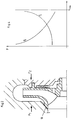
- an angular sealing gap which is formed from a variable axial gap 3 between the end face 4 of the impeller 2 and the housing wall 5 opposite it and a radial gap 6 of constant width between the impeller neck 7 and the housing wall 5 surrounding it.
- Radial sealing gaps 8 and 9 which are formed between a circular and concentric to the axis of the impeller 2 paragraph 10 on the pressure side cover plate 11 of the impeller 2 and paragraphs 12 and 13 on the opposite housing wall 5; a plurality of radially extending housing ribs 14 which are evenly distributed over the circumference and which are delimited radially by the shoulder 13 arranged on a larger diameter and a shoulder 15 provided on a smaller diameter; a variable axial gap 16, which is formed between the shoulder 15 and the pressure-side cover plate 11.
- relief bores 17 are provided, which are arranged in the vicinity of the hub of the impeller 2.
- FIG. 2 essentially corresponds to the embodiment of FIG. 1, the only difference is the suction-side sealing gap, which is designed as a diagonal gap 18 in the device in FIG. 2.
- the advantage of the diagonal gap 18 over the angular gap consisting of the axial gap 3 and the radial gap 6 lies in its better control behavior, as can also be seen from the diagrams in FIGS. 3 and 4.
- the disadvantage is the more complex manufacture of a diagonal gap.
- Figures 3 and 4 already mentioned show the variable forces assigned to the axial movement path s of the impeller 2, the force F2 acting on the pressure side and the force F1 acting on the suction side of the impeller 2.
- the maximum movement path s max should be between 0.8 and 1.2 mm.
- a stable equilibrium position of the rotor is established by coordinating the elements of the axial thrust compensation with one another, i.e. the position and play of the sealing gaps 3, 6, 8, 9, 16, 18 and the position and size of the housing ribs 14 and the relief bores 17 . This fixes the rotor axially without contact during rotation. When deflected from the equilibrium position, relatively high restoring forces ensure that the rotor returns to its original position, which is free of axial force.
- the diagonal gap 18 on the suction side is superior to the combination of the axial gap 3 and the radial gap 6 in its control behavior acting on the axial thrust compensation.
- the device according to the invention can also be realized with a combination of radial (8, 9) and diagonal (22, 23) sealing gaps. Likewise, more than two such sealing gaps (8, 9; 22, 23) can be provided on the pressure side of the impeller (2).
- the housing ribs 14 of the exemplary embodiments were created by milling out the free spaces between the ribs. As a result, the free space areas of paragraphs 13 and 15 were created. It should be mentioned that milling out with a finger cutter results in an arcuate transition of the housing ribs 14 to the walls of the shoulders 13, 15. In a borderline case applicable to short housing ribs, the outer contour of a rib can be semicircular concave on both sides. This has no negative influence on the control behavior of the housing ribs.
Abstract
Description
Für den hydraulischen Axialschubausgleich bei Kreiselpumpen stehen sehr unterschiedliche Maßnahmen und Elemente zur Verfügung. Eine wesentliche Gemeinsamkeit der Mehrzahl der hierfür verwendeten Einrichtungen besteht darin, daß sie für die Bewerkstelligung des hydraulischen Ausgleichs einer in einem Drosselspalt erzeugten Druckdifferenz bedürfen. Da die durch einen Drosselspalt zu erzielende Druckdifferenz aber proportional der Förderhöhe der Kreiselpumpe ist, kann es bei kleineren Förderhöhen, beispielsweise im Überlastbereich der Kreiselpumpe, zu einem Versagen der Ausgleichseinrichtung, also zu einem Anstreifen des Laufrades an einem feststehenden Teil der Kreiselpumpe kommen. Um dies zu verhindern, sah man noch ein Axiallager vor, das den von der hydraulisch wirkenden Ausgleichseinrichtung nicht bewältigten Restschub aufzunehmen vermochte.Very different measures and elements are available for hydraulic axial thrust compensation in centrifugal pumps. An essential common feature of the majority of the devices used for this is that they require a pressure difference generated in a throttle gap in order to accomplish the hydraulic compensation. However, since the pressure difference to be achieved through a throttle gap is proportional to the delivery head of the centrifugal pump, the compensation device may fail at smaller delivery heights, for example in the overload range of the centrifugal pump, i.e. the impeller may rub against a fixed part of the centrifugal pump. In order to prevent this, an axial bearing was also provided, which was able to absorb the residual thrust that the hydraulically acting compensating device could not cope with.
Durch die DE 40 26 905 A1 ist eine Einrichtung zum vollständigen Ausgleich des Axialschubes bei Kreiselpumpen bekannt, die neben einem in herkömmlicher Weise arbeitenden hydraulischen Axialschubausgleich ein zweites, ebenfalls hydraulisch wirkendes Ausgleichssystem besitzt. Dieses zweite System stützt sich auf Mittel, die eine Druckerhöhung im druckseitigen Seitenraum des Laufrades bei einer unter einen vorgegebenen Wert absinkenden Förderhöhe bewirken. Da es somit nicht auf die Pumpenförderhöhe als Wirkparameter angewiesen ist, kann es auch bei kleinen Förderhöhen selbständig einen vollständigen Ausgleich der Axialkräfte erreichen.From DE 40 26 905 A1, a device for complete compensation of the axial thrust in centrifugal pumps is known which, in addition to hydraulic axial thrust compensation, which operates in a conventional manner, has a second, likewise hydraulically acting compensation system. This second system is based on means that a pressure increase in the pressure side space of the impeller at one under cause the predetermined value to drop. Since it is not dependent on the pump head as an effective parameter, it can independently compensate for the axial forces even with small heads.
Auch die vorliegende Erfindung bezweckt einen vollständigen hydraulischen Ausgleich des Axialschubes. Sie geht allerdings einen anderen Weg als die oben geschilderte Einrichtung.The present invention also aims at a complete hydraulic compensation of the axial thrust. However, it takes a different path than the facility described above.
Genau gesagt, handelt es sich bei der Erfindung um eine Einrichtung zum vollständigen Ausgleich des Axialschubes bei Kreiselpumpen, insbesondere bei Kreiselpumpen mit einer spezifischen Drehzahl von mehr als 15 min⁻¹, wobei folgende miteinander im Wirkzusammenhang stehende Merkmale am Laufrad und der das Laufrad umgebenden Gehäusewand der Kreiselpumpe vorhanden sind:
- a) ein zwischen dem Laufradhals und der Gehäusewand gebildeter veränderlicher Dichtspalt;
- b) mehrere auf der Druckseite des Laufrades angeordnete radial verlaufende Gehäuserippen;
- c) ein oder mehrere, auf größerem Durchmesser als die Gehäuserippen angeordnete radiale Dichtspalte, die zwischen kreisringförmig und konzentrisch zur Laufradachse verlaufenden Absätzen gebildet werden, welche an der druckseitigen Deckscheibe des Laufrades und der Gehäusewand angeordnet sind;
- d) mehrere in Nähe der Laufradnabe angeordnete Entlastungsbohrungen;
- e) ein auf einem zwischen den Gehäuserippen und den Entlastungsbohrungen gelegenen, konzentrisch zur Laufradachse verlaufenden Kreisring angeordneter veränderlicher Axialspalt zwischen der druckseitigen Deckscheibe des Laufrades und der Gehäusewand, wobei der Axialspalt zwischen einem an der Deckscheibe oder der Gehäusewand angeordneten Absatz und der ebenen oder ebenfalls mit einem Absatz versehenen Gegenfläche gebildet wird.
- a) a variable sealing gap formed between the impeller neck and the housing wall;
- b) a plurality of radially extending housing ribs arranged on the pressure side of the impeller;
- c) one or more radial sealing gaps arranged on a larger diameter than the housing ribs, which are formed between shoulders which run in a circular shape and concentric to the impeller axis and which are arranged on the pressure-side cover disk of the impeller and the housing wall;
- d) a plurality of relief bores arranged in the vicinity of the impeller hub;
- e) one on a located between the housing ribs and the relief holes, concentric to Impeller axis extending circular ring arranged variable axial gap between the pressure-side cover plate of the impeller and the housing wall, the axial gap being formed between a shoulder arranged on the cover plate or the housing wall and the flat or also provided with a shoulder counter surface.
Der veränderliche, Regelverhalten besitzende Dichtspalt wird gemäß einer ersten Ausgestaltung der Erfindung durch einen Axialspalt zwischen der saugseitigen Stirnfläche des Laufrades und der Gehäusewand gebildet. Empfehlenswert, aber nicht Bedingung, ist ein zusätzlicher, zwischen dem Laufradhals und der Gehäusewand gebildeter Radialspalt, so daß beide Spalte zusammen einen Winkelspalt formen.According to a first embodiment of the invention, the variable sealing gap, which has control behavior, is formed by an axial gap between the suction-side end face of the impeller and the housing wall. An additional radial gap, which is formed between the impeller neck and the housing wall, is recommended, but not a condition, so that both gaps together form an angular gap.
Eine hierzu alternative Ausgestaltung sieht einen als Diagonalspalt ausgebildeten veränderlichen Dichtspalt vor.An alternative embodiment provides a variable sealing gap in the form of a diagonal gap.
In einer bevorzugten Ausführung der Erfindung sind die Gehäuserippen und die diesen jeweils nächstgelegenen Absätze an der Gehäusewand unmittelbar aneinander angrenzend gestaltet.In a preferred embodiment of the invention, the housing ribs and the paragraphs closest to them on the housing wall are designed to be directly adjacent to one another.
Die Einzelmerkmale der Erfindung sind zwar grundsätzlich bekannt. Allerdings wurden sie bisher in anderen Kombinationen als der erfindungsgemäßen eingesetzt, wobei jeweils noch ein zumindest als Notlager dienendes Axiallager erforderlich war. Die Erfindung macht ein Axiallager entbehrlich, weil der Läufer, also die aus dem Laufrad, der Welle und dem Rotor des antreibenden Elektromotors gebildete Einheit, axial berührungsfrei fixiert ist und bei einer Auslenkung aus dieser so eingenommenen Gleichgewichtslage durch hohe Rückstellkräfte wieder in seine axialkraftfreie Ursprungslage zurückgebracht wird.The individual features of the invention are known in principle. However, they have so far been used in combinations other than those according to the invention, in each case still requiring an axial bearing, at least as an emergency bearing. The invention makes an axial bearing dispensable because the rotor, i.e. the unit formed from the impeller, the shaft and the rotor of the driving electric motor, is fixed in an axially contact-free manner and, when deflected from this equilibrium position, is returned to its original position without axial force by high restoring forces becomes.
Anhand mehrerer Ausführungsbeispiele soll dies näher erläutert werden. Die Zeichnung zeigt in
- Fig. 1
- einen Ausschnitt aus einem Kreiselpumpengehäuse mit einer erfindungsgemäßen Einrichtung zum Axialschubausgleich, in
- Fig. 2
- einen der Fig. 1 entsprechenden Ausschnitt aus einer Variante des erfindungsgemäßen Axialschubausgleichs, in
- Fig. 3
- ein Diagramm, welches das Zusammenwirken der am Laufrad der Fig. 1 angreifenden Kräfte zeigt, in
- Fig. 4
- ein entsprechendes Diagramm für die Ausführung der Fig. 2, und in
- Fig. 5
- einen der Fig. 1 entsprechenden Ausschnitt einer weiteren Variante der erfindungsgemäßen Einrichtung.
- Fig. 1
- a section of a centrifugal pump housing with an inventive device for axial thrust compensation, in
- Fig. 2
- a section corresponding to FIG. 1 from a variant of the axial thrust compensation according to the invention, in
- Fig. 3
- a diagram showing the interaction of the forces acting on the impeller of FIG. 1, in
- Fig. 4
- a corresponding diagram for the embodiment of FIG. 2, and in
- Fig. 5
- 1 corresponding section of a further variant of the device according to the invention.
Bei der mit einem Gehäuse 1 und einem Laufrad 2 ausgestatteten Kreiselpumpe der Fig. 1 wirken verschiedene saug- und druckseitig plazierte Elemente zur Erreichung eines vollständigen Axialschubausgleichs zusammen.In the centrifugal pump of FIG. 1 equipped with a housing 1 and an impeller 2, different elements placed on the suction and pressure side interact to achieve complete axial thrust compensation.
Auf der Saugseite befindet sich ein winkelförmiger Dichtspalt, der aus einem veränderlichen Axialspalt 3 zwischen der Stirnfläche 4 des Laufrades 2 und der dieser gegenüberliegenden Gehäusewand 5 und einem Radialspalt 6 unveränderlicher Weite zwischen dem Laufradhals 7 und der diesen umschließenden Gehäusewand 5 gebildet wird.On the suction side there is an angular sealing gap which is formed from a variable axial gap 3 between the end face 4 of the impeller 2 and the
Auf der Druckseite sind mehrere, auf unterschiedlichen Durchmessern angeordnete Elemente vorgesehen. In einer vom größeren zum kleineren Durchmesser reichenden Reihenfolge sind dies:
Radiale Dichtspalte 8 und 9, die zwischen einem kreisringförmig und konzentrisch zur Achse des Laufrades 2 verlaufenden Absatz 10 an der druckseitigen Deckscheibe 11 des Laufrades 2 und Absätzen 12 und 13 an der gegenüberliegenden Gehäusewand 5 gebildet werden;
mehrere radial verlaufende, gleichmäßig über den Umfang verteilte Gehäuserippen 14, welche radial begrenzt werden durch den auf größerem Durchmesser angeordneten Absatz 13 und einen auf kleinerem Durchmesser vorgesehen Absatz 15;
ein veränderlicher Axialspalt 16, der zwischen dem Absatz 15 und der druckseitigen Deckscheibe 11 gebildet wird.On the pressure side there are several elements arranged on different diameters. In an order ranging from the larger to the smaller diameter, these are:
a plurality of radially extending
a variable
Schließlich sind noch mehrere Entlastungsbohrungen 17 vorgesehen, die in der Nähe der Nabe des Laufrades 2 angeordnet sind.Finally, several relief bores 17 are provided, which are arranged in the vicinity of the hub of the impeller 2.
Die in der Fig. 2 dargestellte Variante stimmt im wesentlichen mit der Ausführung der Fig. 1 überein, einen Unterschied bildet allein der saugseitige Dichtspalt, der bei der Einrichtung der Fig. 2 als Diagonalspalt 18 gestaltet ist. Der Vorteil des Diagonalspaltes 18 gegenüber dem aus Axialspalt 3 und Radialspalt 6 bestehenden Winkelspalt liegt in seinem besseren Regelverhalten, wie sich auch anhand der Diagramme der Figuren 3 und 4 erkennen läßt. Der Nachteil liegt in der aufwendigeren Fertigung eines Diagonalspaltes.The variant shown in FIG. 2 essentially corresponds to the embodiment of FIG. 1, the only difference is the suction-side sealing gap, which is designed as a
Die bereits angesprochenen Figuren 3 und 4 zeigen die dem axialen Bewegungsweg s des Laufrades 2 zugeordneten variablen Kräfte, wobei die Kraft F₂ auf die Druckseite und die Kraft F₁ auf die Saugseite des Laufrades 2 wirkt. Der axiale Bewegungsweg s wird begrenzt durch eine Anlage der Stirnfläche 4 an der Gehäusewand 5 (s = 0) und einer Anlage der druckseitigen Deckscheibe 11 am Absatz 15 (smax). Der maximale Bewegungsweg smax sollte zwischen 0,8 und 1,2 mm betragen.Figures 3 and 4 already mentioned show the variable forces assigned to the axial movement path s of the impeller 2, the force F₂ acting on the pressure side and the force F₁ acting on the suction side of the impeller 2. The axial movement path s is limited by an abutment of the end face 4 on the housing wall 5 (s = 0) and an abutment of the pressure-
Durch eine die verschiedenen Einflußparameter berücksichtigende Abstimmung der Elemente des Axialschubausgleichs aufeinander, also Lage und Spiel der Dichtspalte 3, 6, 8, 9, 16, 18 sowie Lage und Größe der Gehäuserippen 14 und der Entlastungsbohrungen 17, stellt sich eine stabile Gleichgewichtslage des Läufers ein. Hierdurch wird der Läufer während der Rotation axial berührungsfrei fixiert. Bei einer Auslenkung aus der Gleichgewichtslage sorgen relativ hohe Rückstellkräfte dafür, daß der Läufer wieder in seine axialkraftfreie Ursprungslage zurückkehrt.A stable equilibrium position of the rotor is established by coordinating the elements of the axial thrust compensation with one another, i.e. the position and play of the
Ursächlich hierfür ist, daß die axial wirkende Kraftkomponente auf die saugseitige Laufraddeckwand über der Spaltweite stark degressiv verläuft, während die entgegengesetzt wirkende Kraftkomponente auf die druckseitige Laufraddeckwand einen progressiven Verlauf besitzt.The reason for this is that the axially acting force component on the suction-side impeller cover wall is very degressive over the gap width, while the oppositely acting force component on the pressure-side impeller cover wall has a progressive course.
Mit dem Grad der Steilheit der den Diagrammen entnehmbaren Kurve des Kraftverlaufs steigern sich bei einer Auslenkung aus der axialkraftfreien Gleichgewichtslage des Läufers die wirksam werdenden Rückstellkräfte. Daher ist es, wie auch die Fig. 4 belegt, der saugseitige Diagonalspalt 18 der Kombination aus Axialspalt 3 und Radialspalt 6 in seinem auf den Axialschubausgleich wirkenden Regelverhalten überlegen.With the degree of steepness of the curve of the force curve which can be seen in the diagrams, the restoring forces which become effective increase when the rotor is deflected from the axial position free of equilibrium. Therefore, as is also shown in FIG. 4, the
In der Fig. 5 ist eine Ausführung der erfindungsgemäßen Einrichtung dargestellt, bei welcher die im Merkmal 1 c des Anspruches 1 genannten Absätze 19 bis 21 so angeordnet sind, daß diagonale Dichtspalte 22, 23 zwischen ihnen gebildet werden. Auf ein Diagramm der am Laufrad 2 angreifender Kräfte F₁ und F₂ wurde bei dieser Ausführung verzichtet.5 shows an embodiment of the device according to the invention, in which the
Die erfindungsgemäße Einrichtung kann auch mit einer Kombination von radialen (8, 9) und diagonalen (22, 23) Dichtspalten verwirklicht werden. Ebenso können jeweils mehr als zwei solcher Dichtspalte (8, 9; 22, 23) auf der Druckseite des Laufrades (2) vorgesehen werden.The device according to the invention can also be realized with a combination of radial (8, 9) and diagonal (22, 23) sealing gaps. Likewise, more than two such sealing gaps (8, 9; 22, 23) can be provided on the pressure side of the impeller (2).
Die Gehäuserippen 14 der Ausführungsbeispiele sind durch Ausfräsen der freien Räume zwischen den Rippen entstanden. Hierdurch wurden gleichzeitig die den freien Raum begrenzenden Flächen der Absätze 13 und 15 geschaffen. Es ist zu erwähnen, daß sich durch das Ausfräsen mit einem Fingerfräser jeweils ein bogenförmiger Übergang der Gehäuserippen 14 zu den Wänden der Absätze 13, 15 ergibt. In einem für kurze Gehäuserippen geltenden Grenzfall kann die Außenkontur einer Rippe auf beiden Seiten halbkreisförmig konkav sein. Dies hat auf das Regelverhalten der Gehäuserippen keinen negativen Einfluß.The
Claims (5)
Applications Claiming Priority (2)
| Application Number | Priority Date | Filing Date | Title |
|---|---|---|---|
| DE4421888 | 1994-06-23 | ||
| DE4421888A DE4421888A1 (en) | 1994-06-23 | 1994-06-23 | Device for axial thrust compensation in centrifugal pumps |
Publications (2)
| Publication Number | Publication Date |
|---|---|
| EP0688955A1 true EP0688955A1 (en) | 1995-12-27 |
| EP0688955B1 EP0688955B1 (en) | 1999-12-29 |
Family
ID=6521263
Family Applications (1)
| Application Number | Title | Priority Date | Filing Date |
|---|---|---|---|
| EP95108418A Expired - Lifetime EP0688955B1 (en) | 1994-06-23 | 1995-06-01 | Device for the compensation of axial thrust in centrifugal pumps |
Country Status (2)
| Country | Link |
|---|---|
| EP (1) | EP0688955B1 (en) |
| DE (2) | DE4421888A1 (en) |
Cited By (8)
| Publication number | Priority date | Publication date | Assignee | Title |
|---|---|---|---|---|
| DE19804768A1 (en) * | 1998-02-06 | 1999-08-12 | Pfeiffer Vacuum Gmbh | Thermal expansion compensation system for rotor bearings in a gas friction pump |
| EP0952352A2 (en) * | 1998-04-20 | 1999-10-27 | Nikkiso Co., Ltd. | Thrust-balancing device |
| EP1296062A1 (en) * | 2001-09-20 | 2003-03-26 | Grundfos a/s | Centrifugal pump |
| EP1306557A3 (en) * | 2001-07-13 | 2004-01-07 | Abs Pump Production Ab | Centrifugal pump |
| GB2442320A (en) * | 2006-09-28 | 2008-04-02 | Snecma | Pump with axial balancing |
| WO2012061011A2 (en) * | 2010-10-25 | 2012-05-10 | Dresser-Rand Company | System and apparatus for reducing thrust forces acting on a compressor rotor |
| CN103850947A (en) * | 2012-11-29 | 2014-06-11 | 上海凯士比泵有限公司 | Anti-cavitation vane pump |
| KR101700332B1 (en) * | 2015-07-29 | 2017-02-14 | 한국해양대학교 산학협력단 | Apparatus for Decreasing Thrust of Radial Inflow Turbine |
Families Citing this family (3)
| Publication number | Priority date | Publication date | Assignee | Title |
|---|---|---|---|---|
| DE102016220976B3 (en) | 2016-10-25 | 2018-03-29 | Engineering Center Steyr Gmbh & Co. Kg | Module for a cooling system of a motor vehicle |
| DE102017211940A1 (en) * | 2017-07-12 | 2019-01-17 | Bayerische Motoren Werke Aktiengesellschaft | Fuel cell system for a motor vehicle and turbomachine for a fuel cell system |
| LU500893B1 (en) * | 2021-11-24 | 2023-05-24 | Wilo Se | Wet rotor pump without axial bearings |
Citations (4)
| Publication number | Priority date | Publication date | Assignee | Title |
|---|---|---|---|---|
| FR413135A (en) * | 1910-02-07 | 1910-08-01 | Farcot Freres Et Cie Soc | Centrifugal pump balancing device |
| FR500808A (en) * | 1919-06-18 | 1920-03-25 | Eugene Beaudrey | System for achieving axial balance of hydraulic turbine wheels or centrifugal pumps |
| FR518914A (en) * | 1914-07-06 | 1921-06-02 | Jean Guerin | automatic axial thrust balancing |
| DE4026905A1 (en) | 1990-08-25 | 1992-02-27 | Klein Schanzlin & Becker Ag | AXIAL SHIFT COMPENSATION FOR CENTRIFUGAL PUMPS |
Family Cites Families (6)
| Publication number | Priority date | Publication date | Assignee | Title |
|---|---|---|---|---|
| DE390366C (en) * | 1924-02-18 | Paul Joseph Charles Marechal | Relief device on turbo machines | |
| DE325196C (en) * | 1920-09-14 | Aeg | Axial pressure compensation device for centrifugal pumps | |
| JPS4938641B1 (en) * | 1970-08-06 | 1974-10-19 | ||
| DE2640990A1 (en) * | 1976-09-11 | 1978-03-16 | Klein Schanzlin & Becker Ag | Centrifugal pump with axially compensated impeller - has axially fixed balance ring behind axially free impeller |
| DE2733631A1 (en) * | 1977-07-26 | 1979-02-08 | Hermetic Pumpen Gmbh | Multistage centrifugal pump - has connections between blades and volute spaces to provide axially centering forces |
| HU217252B (en) * | 1991-03-22 | 1999-12-28 | Warman International Ltd. | Centrifugal slurry pump |
-
1994
- 1994-06-23 DE DE4421888A patent/DE4421888A1/en not_active Withdrawn
-
1995
- 1995-06-01 EP EP95108418A patent/EP0688955B1/en not_active Expired - Lifetime
- 1995-06-01 DE DE59507508T patent/DE59507508D1/en not_active Expired - Lifetime
Patent Citations (4)
| Publication number | Priority date | Publication date | Assignee | Title |
|---|---|---|---|---|
| FR413135A (en) * | 1910-02-07 | 1910-08-01 | Farcot Freres Et Cie Soc | Centrifugal pump balancing device |
| FR518914A (en) * | 1914-07-06 | 1921-06-02 | Jean Guerin | automatic axial thrust balancing |
| FR500808A (en) * | 1919-06-18 | 1920-03-25 | Eugene Beaudrey | System for achieving axial balance of hydraulic turbine wheels or centrifugal pumps |
| DE4026905A1 (en) | 1990-08-25 | 1992-02-27 | Klein Schanzlin & Becker Ag | AXIAL SHIFT COMPENSATION FOR CENTRIFUGAL PUMPS |
Non-Patent Citations (1)
| Title |
|---|
| "centrifugal pump lexicon", KLEIN,SCHANZLIN & BECKER * |
Cited By (15)
| Publication number | Priority date | Publication date | Assignee | Title |
|---|---|---|---|---|
| DE19804768A1 (en) * | 1998-02-06 | 1999-08-12 | Pfeiffer Vacuum Gmbh | Thermal expansion compensation system for rotor bearings in a gas friction pump |
| DE19804768B4 (en) * | 1998-02-06 | 2006-08-24 | Pfeiffer Vacuum Gmbh | Rotor bearing for a gas friction pump |
| EP0952352A2 (en) * | 1998-04-20 | 1999-10-27 | Nikkiso Co., Ltd. | Thrust-balancing device |
| EP0952352A3 (en) * | 1998-04-20 | 2001-05-30 | Nikkiso Co., Ltd. | Thrust-balancing device |
| EP1306557A3 (en) * | 2001-07-13 | 2004-01-07 | Abs Pump Production Ab | Centrifugal pump |
| EP1296062A1 (en) * | 2001-09-20 | 2003-03-26 | Grundfos a/s | Centrifugal pump |
| GB2442320A (en) * | 2006-09-28 | 2008-04-02 | Snecma | Pump with axial balancing |
| FR2906578A1 (en) * | 2006-09-28 | 2008-04-04 | Snecma Sa | PUMP COMPRISING AN AXIAL BALANCING SYSTEM |
| US7686572B2 (en) | 2006-09-28 | 2010-03-30 | Snecma | Pump comprising an axial balancing system |
| GB2442320B (en) * | 2006-09-28 | 2011-09-07 | Snecma | Pump comprising an axial balancing system |
| WO2012061011A2 (en) * | 2010-10-25 | 2012-05-10 | Dresser-Rand Company | System and apparatus for reducing thrust forces acting on a compressor rotor |
| WO2012061011A3 (en) * | 2010-10-25 | 2012-06-28 | Dresser-Rand Company | System and apparatus for reducing thrust forces acting on a compressor rotor |
| CN103850947A (en) * | 2012-11-29 | 2014-06-11 | 上海凯士比泵有限公司 | Anti-cavitation vane pump |
| CN103850947B (en) * | 2012-11-29 | 2017-03-08 | 上海凯士比泵有限公司 | A kind of anti-cavitation vane pump |
| KR101700332B1 (en) * | 2015-07-29 | 2017-02-14 | 한국해양대학교 산학협력단 | Apparatus for Decreasing Thrust of Radial Inflow Turbine |
Also Published As
| Publication number | Publication date |
|---|---|
| DE4421888A1 (en) | 1996-01-04 |
| DE59507508D1 (en) | 2000-02-03 |
| EP0688955B1 (en) | 1999-12-29 |
Similar Documents
| Publication | Publication Date | Title |
|---|---|---|
| DE2328149C2 (en) | Helicopter rotor | |
| DE2307967C2 (en) | Platform for a compressor blade | |
| DE3021189A1 (en) | TURN VIBRATION DAMPER | |
| DE2404580A1 (en) | SERVO VEHICLE STEERING GEAR | |
| EP0688955A1 (en) | Device for the compensation of axial thrust in centrifugal pumps | |
| DE102006043897A1 (en) | shaft coupling | |
| DE3306345C2 (en) | ||
| DE3519598A1 (en) | GASKET, IN PARTICULAR ROLLER BEARING GASKET | |
| DE19736333C1 (en) | Mounting for turbine wheel for fluid pump | |
| DE10233033A1 (en) | Fluid flow machine with excessive rotor-stator contraction ratio | |
| WO1980000733A1 (en) | Wind motor | |
| EP1762737A2 (en) | Hydrodynamic coupling | |
| DE10338010B3 (en) | Hydrodynamic retarder for water has mean number of blades from half sum of rotor and stator blades multiplied by profile displacement factor | |
| DE2137061C2 (en) | Device for adjusting the blades of a controllable pitch propeller | |
| DE3840388C2 (en) | ||
| EP0993552B1 (en) | Liquid ring pump | |
| EP1097306B1 (en) | Oscillating motor | |
| DE2717366A1 (en) | Bladed molecular pump rotor - has blade angle and thickness reducing with increasing distance from centre as defined by formula | |
| EP3159483A1 (en) | Blade support for fixing rotor blades of a thermal fluid flow engine | |
| DE2162408C3 (en) | HYDRO RADIAL PISTON ENGINE | |
| EP1798417B1 (en) | Vacuum pump | |
| EP3877653B1 (en) | Multi-stage hydraulic machine | |
| EP0052251A1 (en) | Regenerative compressor | |
| DE3022090A1 (en) | PRESSURE-OPERATED ROTARY PISTON ENGINE | |
| DE19640734B4 (en) | Thrust bearing for a link pump |
Legal Events
| Date | Code | Title | Description |
|---|---|---|---|
| PUAI | Public reference made under article 153(3) epc to a published international application that has entered the european phase |
Free format text: ORIGINAL CODE: 0009012 |
|
| AK | Designated contracting states |
Kind code of ref document: A1 Designated state(s): DE DK FR GB |
|
| 17P | Request for examination filed |
Effective date: 19960430 |
|
| 17Q | First examination report despatched |
Effective date: 19970129 |
|
| APAB | Appeal dossier modified |
Free format text: ORIGINAL CODE: EPIDOS NOAPE |
|
| APAB | Appeal dossier modified |
Free format text: ORIGINAL CODE: EPIDOS NOAPE |
|
| APAD | Appeal reference recorded |
Free format text: ORIGINAL CODE: EPIDOS REFNE |
|
| APCB | Communication from the board of appeal sent |
Free format text: ORIGINAL CODE: EPIDOS OBAPE |
|
| APCB | Communication from the board of appeal sent |
Free format text: ORIGINAL CODE: EPIDOS OBAPE |
|
| APAB | Appeal dossier modified |
Free format text: ORIGINAL CODE: EPIDOS NOAPE |
|
| GRAG | Despatch of communication of intention to grant |
Free format text: ORIGINAL CODE: EPIDOS AGRA |
|
| GRAH | Despatch of communication of intention to grant a patent |
Free format text: ORIGINAL CODE: EPIDOS IGRA |
|
| GRAH | Despatch of communication of intention to grant a patent |
Free format text: ORIGINAL CODE: EPIDOS IGRA |
|
| GRAA | (expected) grant |
Free format text: ORIGINAL CODE: 0009210 |
|
| AK | Designated contracting states |
Kind code of ref document: B1 Designated state(s): DE DK FR GB |
|
| PG25 | Lapsed in a contracting state [announced via postgrant information from national office to epo] |
Ref country code: GB Free format text: LAPSE BECAUSE OF FAILURE TO SUBMIT A TRANSLATION OF THE DESCRIPTION OR TO PAY THE FEE WITHIN THE PRESCRIBED TIME-LIMIT Effective date: 19991229 |
|
| REF | Corresponds to: |
Ref document number: 59507508 Country of ref document: DE Date of ref document: 20000203 |
|
| PG25 | Lapsed in a contracting state [announced via postgrant information from national office to epo] |
Ref country code: DK Free format text: LAPSE BECAUSE OF FAILURE TO SUBMIT A TRANSLATION OF THE DESCRIPTION OR TO PAY THE FEE WITHIN THE PRESCRIBED TIME-LIMIT Effective date: 20000329 |
|
| ET | Fr: translation filed | ||
| GBV | Gb: ep patent (uk) treated as always having been void in accordance with gb section 77(7)/1977 [no translation filed] |
Effective date: 19991229 |
|
| PLBE | No opposition filed within time limit |
Free format text: ORIGINAL CODE: 0009261 |
|
| STAA | Information on the status of an ep patent application or granted ep patent |
Free format text: STATUS: NO OPPOSITION FILED WITHIN TIME LIMIT |
|
| 26N | No opposition filed | ||
| APAH | Appeal reference modified |
Free format text: ORIGINAL CODE: EPIDOSCREFNO |
|
| PGFP | Annual fee paid to national office [announced via postgrant information from national office to epo] |
Ref country code: DE Payment date: 20140611 Year of fee payment: 20 |
|
| PGFP | Annual fee paid to national office [announced via postgrant information from national office to epo] |
Ref country code: FR Payment date: 20140623 Year of fee payment: 20 |
|
| REG | Reference to a national code |
Ref country code: DE Ref legal event code: R071 Ref document number: 59507508 Country of ref document: DE |