EP0688095A2 - Variable speed generator-motor apparatus capable of improving accuracy of power system - Google Patents
Variable speed generator-motor apparatus capable of improving accuracy of power system Download PDFInfo
- Publication number
- EP0688095A2 EP0688095A2 EP95109225A EP95109225A EP0688095A2 EP 0688095 A2 EP0688095 A2 EP 0688095A2 EP 95109225 A EP95109225 A EP 95109225A EP 95109225 A EP95109225 A EP 95109225A EP 0688095 A2 EP0688095 A2 EP 0688095A2
- Authority
- EP
- European Patent Office
- Prior art keywords
- frequency
- generator
- motor
- power system
- slip
- Prior art date
- Legal status (The legal status is an assumption and is not a legal conclusion. Google has not performed a legal analysis and makes no representation as to the accuracy of the status listed.)
- Granted
Links
Images


Classifications
-
- H—ELECTRICITY
- H02—GENERATION; CONVERSION OR DISTRIBUTION OF ELECTRIC POWER
- H02P—CONTROL OR REGULATION OF ELECTRIC MOTORS, ELECTRIC GENERATORS OR DYNAMO-ELECTRIC CONVERTERS; CONTROLLING TRANSFORMERS, REACTORS OR CHOKE COILS
- H02P21/00—Arrangements or methods for the control of electric machines by vector control, e.g. by control of field orientation
-
- H—ELECTRICITY
- H02—GENERATION; CONVERSION OR DISTRIBUTION OF ELECTRIC POWER
- H02P—CONTROL OR REGULATION OF ELECTRIC MOTORS, ELECTRIC GENERATORS OR DYNAMO-ELECTRIC CONVERTERS; CONTROLLING TRANSFORMERS, REACTORS OR CHOKE COILS
- H02P23/00—Arrangements or methods for the control of AC motors characterised by a control method other than vector control
- H02P23/08—Controlling based on slip frequency, e.g. adding slip frequency and speed proportional frequency
-
- H—ELECTRICITY
- H02—GENERATION; CONVERSION OR DISTRIBUTION OF ELECTRIC POWER
- H02P—CONTROL OR REGULATION OF ELECTRIC MOTORS, ELECTRIC GENERATORS OR DYNAMO-ELECTRIC CONVERTERS; CONTROLLING TRANSFORMERS, REACTORS OR CHOKE COILS
- H02P9/00—Arrangements for controlling electric generators for the purpose of obtaining a desired output
- H02P9/007—Control circuits for doubly fed generators
-
- H—ELECTRICITY
- H02—GENERATION; CONVERSION OR DISTRIBUTION OF ELECTRIC POWER
- H02P—CONTROL OR REGULATION OF ELECTRIC MOTORS, ELECTRIC GENERATORS OR DYNAMO-ELECTRIC CONVERTERS; CONTROLLING TRANSFORMERS, REACTORS OR CHOKE COILS
- H02P9/00—Arrangements for controlling electric generators for the purpose of obtaining a desired output
- H02P9/42—Arrangements for controlling electric generators for the purpose of obtaining a desired output to obtain desired frequency without varying speed of the generator
Definitions
- the present invention relates to a variable speed generator-motor apparatus capable of improving accuracy of a power system.
- a variable speed generator-motor apparatus is utilized by using a wound-rotor induction generator-motor in the place of a conventional generator-motor apparatus using a synchronous machine.
- the variable speed generator-motor apparatus comprises a wound-rotor induction generator-motor (hereunder called as an induction machine) having a primary winding connected to a power system and a secondary winding excited by an alternating current (AC), and a prime mover as a load united with a generator shaft of the induction machine. Since the generator-motor apparatus can be driven at a rotating speed different from a synchronous speed determined by a system frequency, it is possible to optimize operation efficiency and to suppress jolting in the conventional synchronous machine at a system trouble.
- variable speed generator-motor apparatus has features that optimum control of the rotating speed can be performed without fixing to the synchronous speed determined by the system frequency, and that the secondary winding is excited by an alternating current having a frequency determined by a difference between the synchronous speed and rotating speed.
- variable speed generator-motor apparatus can control active power of the induction machine by an alternating current excitation control device, and since torque of the prime mover as the load can be controlled by a prime-mover/load control device, both of the alternating current excitation device and the prime-mover/load control device can control the rotating speed (refer to a report No. 1026 of a national convention of the Japanese institution of electricity on Syowa 61st -1986-).
- Japanese patent Applications Laid-open No. 61-247299 (1986) and No. 3-51910 (1991) shows an example in which an AC excitation control device controls a rotating speed.
- Japanese patent application Laid-open No. 1-231698 (1989) shows an example in which, though it does not show a prime mover in any figures, a prime-mover/load control device controls a rotating speed.
- variable speed generator-motor apparatus There will be described conventional configuration and function of a variable speed generator-motor apparatus by an example of a variable speed pumped-storage power generation system.
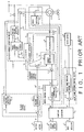
- FIG. 1 shows a system constitution of the AC excitation control device.
- a wound-rotor induction generator-motor 1 (hereunder called as an induction machine) has a rotor which is connected to a reversible pump turbine 2, and a secondary winding which is excited by a cycloconverter 3 as a frequency converter by an alternating current.
- a function generator 8 obtains an optimum rotating speed and guide vane opening degree on the basis of an output P* of a reactive power setter 6 and an output H of a head detector 7 to output a rotating speed command N* and a guide vane opening degree command Y*, respectively.
- a guide vane opening control device 140 comprises a guide vane opening controller 41 and a subtracter 42 for calculating a difference between the guide vane opening degree command Y* and an actual guide vane opening degree Y, and controls the actual guide vane opening degree Y of the reversible pump turbine 2 to coincide with the guide vane opening degree command Y* through a servo motor 4.
- a voltage control device 120 comprises a voltage controller 21 and a subtracter 22 for calculating a difference between an output V* of the voltage setter 5 and a primary voltage V1 of the induction machine 1 detected by a voltage transformer 17 and a voltage detector 23, and calculates a d-axis current command value I d * to cause the output V* of the voltage setter 5 to be equal to the primary voltage V1 of the induction machine 1.
- a d-axis current is a current component which lags with 90 degree from the primary voltage V1 of the induction machine 1, and is proportional to reactive power.
- a speed control device 130 comprises a speed controller 31 and a subtracter 32 for calculating a difference between a rotating speed command N* and a speed signal N R which are respectively obtained by a speed signal generator 33 and a speed detector 34, in which the generator 33 is installed at the rotor of the induction machine 1 and outputs an alternating current signal having a frequency in proportion to a rotating speed, an detector 34 generates a voltage in proportion to the frequency.
- the device 130 calculates a q-axis current command value I q to cause the speed signal N R to be equal to the rotation speed command N* on the basis of the difference.
- An Idq-axis current detection device 100 comprises a phase locked loop (PLL) circuit 16 for detecting a phase reference ⁇ j ⁇ R of a secondary current of the induction machine 1 on the basis of the phase ⁇ j ⁇ 1 of the primary voltage V1 of the induction machine 1 detected by the voltage transformer 17 and a phase detector 19, a current detector 15 for detecting a secondary current i2 of the induction machine 1, and an Id/Iq-axis current detector 14 for detecting an Idq-axis current on the basis of the secondary current i2 and its phase reference ⁇ j ⁇ 2 of the secondary current of the induction machine 1, so as to detect the d-axis current Id and q-axis current Iq of the secondary current of the induction machine 1.
- PLL phase locked loop
- phase signals " ⁇ j ⁇ R ", " ⁇ j ⁇ 1” and “ ⁇ j ⁇ 2” are respectively corresponding to a vector " cos ⁇ R +jsin ⁇ R " determined by an electric angle ⁇ R of the rotor, a vector " cos ⁇ 1+jsin ⁇ 1” determined by the phase angle ⁇ 1 of the voltage V1, and a vector " cos ⁇ 2+jsin ⁇ 2 " determined by " ⁇ 1- ⁇ R " (called as ⁇ 2).
- FIG. 2 since respective configurations are the same as those shown in FIG. 1, there is omitted the duplicationed description with respect to the induction machine 1; the pump turbine 2; the cycloconverter 3; active power setter 6; the head detector 7; the function generator 8; the servo motor 4; the guide vane opening control device 140 including the guide vane opening controller 41 and subtracter 42; the voltage setter 5; the voltage control device 120 including the voltage transformer 17, voltage detector 23, subtracter 22 and voltage controller 21; the Idq-axis detection device 100 including the phase detector 19 of the rotor, voltage transformer 17, phase detector 18 of system frequency, PLL circuit 16, current detector 15 and Id/Iq-axis detector 14; and the secondary current control device 110 including the subtracter 12 and current controller 11.
- a speed control device 160 is provided in the place of the speed control device 130 and comprises a speed controller 31, subtracter 32 and adder 33 to correct an output Nc of the speed controller and guide vane opening degree command value Y* so as to calculate a corrected guide vane opening degree command value Y*1, and that an active power control portion 170 is added and comprises a current detector 71, active power detector 72, subtracter 73 and active power controller 74.
- the active power controller 74 outputs a q-axis current command value I q * in the manner of coinciding an output P of the active power detector 72 with an active power command value P*.
- the speed control device 160 outputs the signal Nc for correcting the guide vane opening command value Y* to coincide the rotating speed N R with the speed command value N*, and the guide vane control device 140 operates in the manner of coinciding the guide vane opening degree Y with the corrected guide vane opening degree command value Y1*. If the function generator operates properly, the corrected signal Nc is zero.
- variable speed generator-motor apparatus since it is possible to control the system at an optimum rotating speed in practice without a fix at a synchronous speed determined by a system frequency, the following problems occur by controlling the rotating speed apart from the system frequency in spite of various features.
- a first problem resides in that a large change of a power system frequency or rotating speed causes operation of the system to be disabled.
- a voltage occurring in the secondary winding of the induction machine 1 is proportional to a slip S.
- the cycloconverter can not control a secondary current of the induction machine 1, thereby disabling an continuity of operation.
- a second problem resides in that synchronizing power can not contribute a suppression of frequency changes of the power system because synchronizing power is suppressed.
- a synchronizing power is called with respect to an increase of the output and a decrease of the input of the synchronous machine in this case.
- the synchronizing power is a change in the direction of a suppression to the decrease of the power system frequency so as to contribute a suppression of a change of the power system frequency.
- variable speed generator-motor apparatus when the power system frequency f1 decreases as shown in FIG. 4, even though the rotating speed also decreases by the synchronizing power, since the rotating speed is suppressed to the speed N R as described above in spite of the power system frequency, both of an increase of the output of the induction machine (or a decrease of the input of the induction machine) and a decrease of the rotating speed do not occur because of a cancellation of the synchronizing power.
- FIG. 4(b) shows an example that the generator-motor apparatus rotates at a speed lower than the synchronous speed N O .
- variable speed generator-motor apparatus does not contribute a suppression of the frequency change of the power system.
- a third problem resides in that it is impossible to contribute the suppression of the frequency change of the power system because of none of governor free function.
- a governor free function in which an output of the prime mover changes to suppress the decrease of the rotating speed.
- the governor free function contributes the suppression of the frequency change in the power system
- a governor free function as a first definition is a function that changes an output of the prime mover to suppress the decrease of the rotating speed of the prime mover with such the decrease of the frequency of the power system.
- the method uses the generator-motor apparatus having the induction machine, which further has a slip frequency limit device, as a third conventional example shown in FIG. 3, comprising a slip frequency detector 81 for detecting an excitation frequency f2 (namely, a slip frequency f s ) of the induction machine 1 on the basis of a PLL output signal, a slip excess detector 82 for detecting an amount that the slip frequency f s is over a slip width set value f m , a first order lag calculator 83, and a subtracter 84 for subtracting an output P c of the first order lag calculator 83 from an active power command value P* to output a corrected active power command value P1*.
- a slip frequency detector 81 for detecting an excitation frequency f2 (namely, a slip frequency f s ) of the induction machine 1 on the basis of a PLL output signal
- a slip excess detector 82 for detecting an amount that the slip frequency f s is over a slip width set value f
- the method can not solve the second and third problems, it does not change the conventional method with respect to a suppression of the frequency change in the power system.
- the method uses a generator-motor apparatus, as a fourth example shown in FIG. 6, comprising in addition to elements shown in FIG. 1 a power system frequency change suppression means including a frequency detector 85, change rate calculator 86, and adder 84.
- a power system frequency change suppression means including a frequency detector 85, change rate calculator 86, and adder 84.
- the power system frequency change suppression means corrects an active power command value corresponding to a frequency change in the power system, the active power changes as a result in the direction to suppress the frequency change in the power system, thereby contributing a suppression of the frequency change in the power system.
- the method can not solve the first and second problems, thereby only resulting an incomplete improvement.
- the first object of the present invention is to provide a variable speed generator-motor apparatus without an operation failure even when a power system frequency largely changes.
- the second object of the present invention is to utilize a variable speed generator-motor apparatus without a cancellation of synchronizing force thereby to contribute a suppression of a frequency change in a power system.
- the third object of the present invention is to provide a variable speed generator-motor apparatus to which a control function is added for suppressing a frequency change in a power system.
- a variable speed generator-motor apparatus comprises a wound-rotor induction generator-motor having a primary winding connected to a power system, a secondary winding excited by an alternating current (AC) and a generator shaft; a prime-mover/load united with the generator shaft; frequency detection means for detecting an AC excitation frequency on the basis of power data including a frequency and a voltage phase in the power system and data of the generator shaft; means for generating a slip frequency command value in the generator-motor; and frequency control means for controlling the generator-motor in the manner that the AC excitation frequency is set to the slip frequency command value.
- AC alternating current
- a first aspect of the present invention is to provide a variable speed generator-motor apparatus comprising a wound-rotor induction generator-motor having a primary winding connected to a power system and a secondary winding excited by an alternating current; a prime-mover/load united to a generator shaft of the wound-rotor induction generator-motor; frequency detection means for detecting a frequency of an AC excitation on the basis of any of frequency and voltage phase of the power system and any of rotating speed and rotating angle of the generator shaft; and slip frequency control means for controlling the wound-rotor induction generator-motor in the manner that the frequency of the AC excitation becomes to a slip frequency command value.
- a second aspect of the present invention is to provide a variable speed generator-motor apparatus further comprising means for limiting within a reference value a slip frequency command value outputted from the slip frequency control means in addition to the apparatus of the first aspect.
- a third aspect of the present invention is to provide a variable speed generator-motor apparatus comprising a wound-rotor induction generator-motor having a primary winding connected to a power system and a secondary winding excited by an alternating current; a prime-mover/load united to a generator shaft of the wound-rotor induction generator-motor; frequency detection means for detecting a frequency of an AC excitation on the basis of any of frequency and voltage phase of the power system and any of rotating speed and rotating angle of the generator shaft; and slip frequency control means for controlling the wound-rotor induction generator-motor in the manner that the frequency of the AC excitation becomes to a slip frequency command value.
- a fourth aspect of the present invention is to provide a variable speed generator-motor apparatus comprising a wound-rotor induction generator-motor having a primary winding connected to a power system and a secondary winding excited by an alternating current; a prime-mover/load united to a generator shaft of the wound-rotor induction generator-motor; frequency detection means for detecting a frequency of an AC excitation on the basis of any of frequency and voltage phase of the power system and any of rotating speed and rotating angle of the generator shaft; slip frequency control means for controlling the wound-rotor induction generator-motor in the manner that the frequency of the AC excitation becomes to a slip frequency command value; and prime-mover/load torque correction means for correcting a torque of the prime-mover/load corresponding to a frequency change in the power system.
- a fifth aspect of the present invention is to provide a variable speed generator-motor apparatus comprising a wound-rotor type induction generator-motor having a primary winding connected to a power system and a secondary winding excited by an alternating current; a prime-mover/load united to a generator shaft of the wound-rotor induction generator-motor; frequency detection means for detecting a frequency of an AC excitation on the basis of any of frequency and voltage phase of the power system and any of rotating speed and rotating angle of the generator shaft; slip frequency control means for controlling the wound-rotor induction generator-motor in the manner that the frequency of the AC excitation becomes to a slip frequency command value; and slip frequency command value correction means for correcting the slip frequency command value corresponding to the rotating speed of the generator shaft.
- a sixth aspect of the present invention is to provide a variable speed generator-motor apparatus comprising a wound-rotor induction generator-motor having a primary winding connected to a power system and a secondary winding excited by an alternating current; a prime-mover/load united to a generator shaft of the wound-rotor induction generator-motor; frequency detection means for detecting a frequency of an AC excitation on the basis of any of frequency and voltage phase of the power system and any of rotating speed and rotating angle of the generator shaft; slip frequency control means for controlling the wound-rotor induction generator-motor in the manner that the frequency of the AC excitation becomes to a slip frequency command value; and slip frequency command value correction means for correcting the slip frequency command value corresponding to a frequency change in the power system.
- the generator-motor apparatus comprises the slip frequency control means, the slip frequency f s , namely "f1-f R ", is controlled to be constant, thereby resulting a numerator of the equation (1) to be constant. Accordingly, even though the frequency in the power system changes, the slip does not change. For example, when f1 is 100% and f R is 95% to cause the slip S to be 5%, even though f1 changes to be 105%, f R is controlled to be 100% because f S is constant, thereby resulting a small change of the slip S because of only changing the slip S from 5% to 4.76%.
- the rotating speed changes with the same rate of the frequency change in the power system in order to prevent the change of the slip frequency.
- the change is equal to a change of the rotating speed of the induction machine by synchronizing power, and means that the variable speed generator-motor does not cancel synchronizing power.
- variable speed generator-motor apparatus constituted in the second aspect. Since the apparatus according to the second aspect comprises the means for limiting the slip frequency command value within the reference value, the slip is limited within the reference value as described above even though the frequency in the power system changes.
- variable speed generator-motor apparatus constituted in the third aspect.
- the apparatus according to the third aspect corrects a torque of the prime-mover/load with ⁇ M in proportion to a change ⁇ N of the rotating speed
- a correction amount ⁇ M is proportional to a change amount of the frequency f1 in the power system to correct the active power of the induction machine 1 with ⁇ M , because the slip frequency constantly controls the frequency f2.
- the apparatus using the means of the third aspect shows a governor free function that causes the torque of the prime-mover/load and the active power of induction machine 1 to change corresponding to the change of the frequency f1 of the power system.
- variable speed generator-motor apparatus There is described a function of the variable speed generator-motor apparatus according to the fourth aspect of the present invention. Since the apparatus of the fourth aspect corrects the torque of the prime-mover/load and the active power of the induction machine 1 corresponding to the frequency change in the power system, the apparatus of the fourth aspect shows a governor free function in the same manner of the third aspect.
- the apparatus of the fifth aspect corrects the slip frequency command value f s * by a value of which the frequency change ⁇ f1 of the power system is integrated. Since the slip frequency control corrects the frequency f2 to coincide with the slip frequency command value f s *, a correction amount ⁇ P E of the active power of the induction machine 1 is a value corresponding to the frequency change ⁇ f1 in the power system. The correction amount ⁇ P E of the active power changes with a correction of the slip frequency command value f2* as will be mentioned later.
- the apparatus according to the sixth aspect of the present invention corrects the slip frequency command value f s * corresponding to a difference ⁇ f1 between the power system frequency and the reference frequency. Since the slip frequency controls the frequency f2 to coincide with the slip frequency command value f s *, a correction amount ⁇ P E of the active power of the induction machine 1 is a value corresponding to the frequency change ⁇ f1 in the power system. The correction amount ⁇ P E of the active power changes with a correction of the slip frequency command value f2* as will be mentioned later.
- variable speedgenerator-motor apparatus There will be described in detail preferred embodiments of a variable speedgenerator-motor apparatus according to the present invention with reference to the attached drawings.
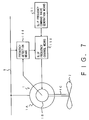
- the generator-motor apparatus comprises a wound-rotor induction generator-motor 1 including a primary winding 1A connected to a power system 9, a secondary winding 1B excited by an alternating current (AC), and a generator shaft 1C; a prime-mover/load 2 united to the generator shaft 1C; frequency detection means 100 for detecting an AC excitation frequency on the basis of power data in the power system 9 and the data of the generator shaft 1C; slip frequency command value generation means 51 for generating a slip frequency command value of the generator-motor 1; and slip frequency control means 150 for controlling the generator-motor 1 in the manner that the AC excitation frequency outputted from the frequency detection means 100 coincides with the slip frequency command value outputted from the means 51.
- variable speed generator-motor apparatus according to a first embodiment relevant to the first aspect of the present invention with reference to FIG. 8 showing a constitution of the first embodiment.
- the generator-motor apparatus comprises an induction machine 1, a pumped turbine 2, a cycloconverter 3, an active power setter 6, a head detector 7, a function generator 8, a servo motor 4, a guide vane opening control device 140 including a guide vane opening controller 41 and subtracter 42, a voltage setter 5, a voltage transformer 17, a voltage control device 120 including a voltage controller 21, subtracter 22 and voltage detector 23, an Idq axis current detecting device 100 including an I d /I q -axis current detector 14, current detector 15, PLL circuit 16, voltage transformer 17, system frequency phase detector 18 and rotor phase detector 19, and a secondary current control device 110 including a current controller 11 and subtracter 12.
- the PLL circuit 16 as an example comprises, as shown in FIG. 9, a vector subtracter 161 for obtaining a difference ⁇ j ⁇ and ⁇ j( ⁇ R ⁇ ⁇ 2) , a proportion and integral calculator 162, a vector generator 163, and a vector adder 164.
- the secondary current control device 110 comprises a subtracter 12 for calculating a difference between a d-axis current command value I d * and a d-axis current I d , a subtracter 13 for calculating a difference between a q-axis current command value I q * and a q-axis current I q , and a current controller 11, thereby controlling an arc angle of the cycloconverter in the manner that the d-axis current I d coincides with the d-axis current I d with the d-axis current command value I d *, and the q-axis current I q coincides with the q-axis current command value I q *.
- the generator-motor apparatus according to the first embodiment shown in FIG. 8 is different from the conventional apparatus at the point of provision of a slip frequency control device 150 in the place of the speed control device 130.
- the slip frequency control device 150 comprises a slip frequency command value generator 51 for calculating a slip frequency command value f S *, a subtracter 52 for calculating a difference between the slip frequency command value f S * and an internal output f2 of the PLL circuit 16, and a slip frequency controller 53 for outputting a q-axis current command value I q * on the basis of the difference calculated by the subtracter 52.
- f2 N1 - N R
- the apparatus is a variable speed generator-motor apparatus without a cancellation of synchronizing power.
- the generator-motor apparatus rotates at a speed lower than the synchronous speed N O .
- the rotating speed of the variable speed generator-motor apparatus is controlled to be " N*+N1-N0 ". Since N* is enough to be large against “N1-N0", it is possible to operate the apparatus near the optimum rotating speed N*, thereby changing the rotating speed from N* to "N1-N0" corresponding to the frequency change of the power system.
- the change of the rotating speed corresponding to the frequency change of the power system means that synchronizing power is not cancelled, thereby contributing the suppression of the frequency change in the power system.
- the apparatus of the first embodiment uses the pumped turbine as the prime-mover/load, it is possible to obtain the same effect of the first embodiment by using a rotational body having inertia such as a reversible pump turbine, pump, steam turbine, flywheel, and wind mill.
- a rotational body having inertia such as a reversible pump turbine, pump, steam turbine, flywheel, and wind mill.
- variable speed generator-motor apparatus according to the second embodiment of the present invention as another example of the slip frequency detection method with reference to FIG. 12.
- the apparatus according to the present invention can obtain the same effect by means of a detection of a slip frequency f S as "f1-N R " on the basis of the power system frequency f1 and the rotating speed N R in the place of an internal detection of the slip frequency in the PLL circuit.
- FIG. 12 shows another constitution of the slip frequency detection circuit.
- the frequency detection circuit 165 in FIG. 12 is added to the apparatus in FIG. 12 and comprises a speed signal detector 33, speed detector 34, system frequency detector 35 and subtracter 36.
- the apparatus according to the second embodiment has a difference to use an output signal f S of the subtracter 36 in the place of the output signal f2 of the PLL circuit shown in FIG. 8. Since function and effect are the same as the first embodiment shown in FIG. 8, a duplicated description is omitted.
- any more methods for detecting the slip frequency may be applied to the present invention to obtain the above function and effect.
- variable speed generator-motor apparatus according to a third embodiment corresponding to the second aspect of the present invention with reference to the figure.
- the apparatus of the third embodiment changes the slip frequency command value generator 51 of the first embodiment shown in FIG. 10 to a constitution shown in FIG. 13, namely, a limiter 513 is added to an output of the coefficient multiplier 512.
- the slip frequency command value f S * is limited to the reference value in the third embodiment, the excitation frequency f2 (namely, the slip frequency f S ) is not over the reference value because of being controlled to be f S *.
- the slip frequency in the third embodiment is not over the reference value, the slip is not over the reference value either. Therefore, operation failure does not occur even when the power system frequency largely changes, thereby maintaining stable operation.
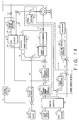
- FIG. 14 shows a constitution of the apparatus according to the fourth embodiment.
- the apparatus shown in FIG. 14 comprises rotating speed detection means having a speed signal detector 33 and speed detector 34, and torque correction means 160 in addition to the constitution shown in FIG. 8.
- the torque correction means 160 comprises a subtracter 61 for calculating a difference between a speed command value N* and a rotating speed N, a torque corrector 62 for calculating a signal ⁇ c to correct a guide vane opening command value Y* on the basis of an output of the subtracter 61, and an adder 63 for adding the correction signal ⁇ c with the guide vane opening command value Y*.
- the equation (6) can be established by a slip frequency control
- the following equation (8) represents an amount ⁇ M of which a torque of the prime-mover/load is corrected by the correction signal ⁇ c :
- the slip frequency control corrects active power in the induction machine 1 with the amount ⁇ M to suppress a change in the slip. Therefore, the active power in the induction machine 1 is corrected corresponding to the frequency change (f1-f0) in the power system.
- the apparatus of the fourth embodiment can exhibits so-called governor free function for changing torque of the prime-mover/load and active power in the nduction machine 1, it is possible to contribute more and more suppression of the frequency change in the power system.
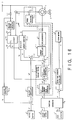
- FIG. 15 shows a constitution of the apparatus of the fifth embodiment.
- the apparatus comprises torque correction neans 161 in addition to the constitution shown in FIG. 8.
- the torque correction means 161 comprises a frequency deviation detector 64 for detecting deviation ⁇ f1 between the power system frequency and the reference frequency, a torque corrector 65 for calculating the correction signal ⁇ c for correcting the guide vane opening command value Y* on the basis of the deviation ⁇ f1, and an adder 63 for adding the correction signal ⁇ c with the guide vane opening degree command value Y*.
- variable speed generator-motor apparatus including the means of the fourth aspect has the so-called governor free function which changes torque of the prime-mover/load and active power in the induction machine 1 corresponding to a change ⁇ f1 of the power system frequency f1.
- the fifth embodiment has a specific effect for exhibiting a governor free function which changes torque of the prime-mover/load and active power of the induction machine 1 corresponding to the frequency change of the power system in addition to the specific effect of the first and second embodiments corresponding to the first aspect, it is possible to contribute a suppression of the frequency change of the power system.
- FIG. 16 shows a constitution of the apparatus according to the sixth embodiment.
- the apparatus comprises rotating speed detection means, and a slip frequency control device 151.
- the rotating speed detection means is newly added in the sixth embodiment and comprises a speed signal generator 33 and a speed detector 34.
- the device 151 is provided in the place of the slip frequency command value generator 51 and comprises a slip frequency command value generator 54 for calculating a slip frequency command value f S * on the basis of the speed command value N* and the rotating speed N R .
- ⁇ P E is a correction amount of active power in the induction machine 1
- d/dt denotes a differentiation. Active power, rotation speed and frequency have a positive generation direction, respectively.
- the apparatus of the sixth embodiment can change active power in the apparatus corresponding to the frequency change in the power system in addition to effects of the fist and second embodiments corresponding to the first aspect of the present invention, it is possible to more and more contribute the suppression of the frequency change in the power system.
- the function cannot be realized by the generator-motor apparatus using a synchronous machine disabling slip frequency control, thereby resulting characteristics of the variable speed generator-motor apparatus according to the present invention.
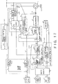
- FIG. 17 is a block diagram of the apparatus according to the seventh embodiment.
- the apparatus according to the seventh embodiment shown in FIG. 13 adds a frequency deviation detector 64 for detecting a deviation ⁇ f1 between the power system frequency and the reference frequency, and comprises a slip frequency command value generator 55 for constituting a slip frequency control device 152 in the place of the slip frequency command value generator 51.
- the slip frequency command value generator 55 calculates a slip frequency command value f S * on the basis of the speed command value N* and the rotating speed and the deviation ⁇ f1.
- df S */dt - ⁇ f1/T N Since the equation (16) has results as the same as those of the equation (12), function of the seventh embodiment is the same as the function of the sixth embodiment.
- the apparatus of the seventh embodiment can change active power in the apparatus corresponding to a change of the power system frequency in addition to the effects of the first and second embodiments according to the first aspect, it is possible to more and more contribute the suppression of the frequency change in the power system.
- the function can not be realized by the generator-motor apparatus using the synchronous machine disabling the slip frequency control because a direct current excites the synchronous machine, thereby resulting a characteristic effect of the variable speed generator-motor apparatus according to the present invention.
Abstract
Description
- The present invention relates to a variable speed generator-motor apparatus capable of improving accuracy of a power system.
- A variable speed generator-motor apparatus is utilized by using a wound-rotor induction generator-motor in the place of a conventional generator-motor apparatus using a synchronous machine. The variable speed generator-motor apparatus comprises a wound-rotor induction generator-motor (hereunder called as an induction machine) having a primary winding connected to a power system and a secondary winding excited by an alternating current (AC), and a prime mover as a load united with a generator shaft of the induction machine. Since the generator-motor apparatus can be driven at a rotating speed different from a synchronous speed determined by a system frequency, it is possible to optimize operation efficiency and to suppress jolting in the conventional synchronous machine at a system trouble. However, it is necessary to excite a secondary winding by an alternating current having a frequency decided by a difference between synchronous speed and rotating speed for operating the machine at a rotating speed different from a synchronous speed (see the journal of the Japanese institution for electricity, March, 1986).
- Here, a synchronous speed N₁ is determined by a system frequency f₁ and a number of polarities p of the generator-motor and N₁ is defined as "

- The variable speed generator-motor apparatus has features that optimum control of the rotating speed can be performed without fixing to the synchronous speed determined by the system frequency, and that the secondary winding is excited by an alternating current having a frequency determined by a difference between the synchronous speed and rotating speed.
- Since the variable speed generator-motor apparatus can control active power of the induction machine by an alternating current excitation control device, and since torque of the prime mover as the load can be controlled by a prime-mover/load control device, both of the alternating current excitation device and the prime-mover/load control device can control the rotating speed (refer to a report No. 1026 of a national convention of the Japanese institution of electricity on Syowa 61st -1986-).
- Japanese patent Applications Laid-open No. 61-247299 (1986) and No. 3-51910 (1991) shows an example in which an AC excitation control device controls a rotating speed. Further, Japanese patent application Laid-open No. 1-231698 (1989) shows an example in which, though it does not show a prime mover in any figures, a prime-mover/load control device controls a rotating speed.
- Since the example of the application No. 1-231698 has the AC excitation device (cycloconverter) for controlling only reactive power, a rotating speed is controlled by other control devices such as a prime mover control device which is not shown in the figure.
- There will be described conventional configuration and function of a variable speed generator-motor apparatus by an example of a variable speed pumped-storage power generation system.
- In the following description, all of variables and constants are dimensionless values caused by respective standard values of it, and symbols εjϑ1, εjϑ2, εjϑR, εj (ϑ2+φ*) means exponent functions.
- For example, there is

- At first, there is described a first example of a variable speed pumped-storage generation system in which an AC excitation control device controls a rotating speed. FIG. 1 shows a system constitution of the AC excitation control device.
- In FIG.1, a wound-rotor induction generator-motor 1 (hereunder called as an induction machine) has a rotor which is connected to a
reversible pump turbine 2, and a secondary winding which is excited by acycloconverter 3 as a frequency converter by an alternating current. During a variable speed operation, afunction generator 8 obtains an optimum rotating speed and guide vane opening degree on the basis of an output P* of areactive power setter 6 and an output H of ahead detector 7 to output a rotating speed command N* and a guide vane opening degree command Y*, respectively. - A guide vane
opening control device 140 comprises a guide vane opening controller 41 and a subtracter 42 for calculating a difference between the guide vane opening degree command Y* and an actual guide vane opening degree Y, and controls the actual guide vane opening degree Y of thereversible pump turbine 2 to coincide with the guide vane opening degree command Y* through aservo motor 4. - A
voltage control device 120 comprises avoltage controller 21 and asubtracter 22 for calculating a difference between an output V* of thevoltage setter 5 and a primary voltage V₁ of theinduction machine 1 detected by avoltage transformer 17 and avoltage detector 23, and calculates a d-axis current command value Id* to cause the output V* of thevoltage setter 5 to be equal to the primary voltage V₁ of theinduction machine 1. - Here, a d-axis current is a current component which lags with 90 degree from the primary voltage V₁ of the
induction machine 1, and is proportional to reactive power. - A
speed control device 130 comprises aspeed controller 31 and asubtracter 32 for calculating a difference between a rotating speed command N* and a speed signal NR which are respectively obtained by aspeed signal generator 33 and aspeed detector 34, in which thegenerator 33 is installed at the rotor of theinduction machine 1 and outputs an alternating current signal having a frequency in proportion to a rotating speed, andetector 34 generates a voltage in proportion to the frequency. Thedevice 130 calculates a q-axis current command value Iq to cause the speed signal NR to be equal to the rotation speed command N* on the basis of the difference. - An Idq-axis
current detection device 100 comprises a phase locked loop (PLL)circuit 16 for detecting a phase reference εjϑR of a secondary current of theinduction machine 1 on the basis of the phase εjϑ1 of the primary voltage V₁ of theinduction machine 1 detected by thevoltage transformer 17 and aphase detector 19, acurrent detector 15 for detecting a secondary current i₂ of theinduction machine 1, and an Id/Iq-axiscurrent detector 14 for detecting an Idq-axis current on the basis of the secondary current i₂ and its phase reference εjϑ2 of the secondary current of theinduction machine 1, so as to detect the d-axis current Id and q-axis current Iq of the secondary current of theinduction machine 1. - Here, the phase signals "εjϑR", "εjϑ1" and "εjϑ2" are respectively corresponding to a vector "


- Next, there is described a second example of the conventional variable speed pumped-storage generation system in which a guide vane opening control device controls a rotating speed with reference to FIG. 2 showing a system constitution thereof.
- In FIG. 2, since respective configurations are the same as those shown in FIG. 1, there is omitted the duplicationed description with respect to the
induction machine 1; thepump turbine 2; thecycloconverter 3;active power setter 6; thehead detector 7; thefunction generator 8; theservo motor 4; the guide vaneopening control device 140 including the guide vane opening controller 41 and subtracter 42; thevoltage setter 5; thevoltage control device 120 including thevoltage transformer 17,voltage detector 23, subtracter 22 andvoltage controller 21; the Idq-axis detection device 100 including thephase detector 19 of the rotor,voltage transformer 17,phase detector 18 of system frequency,PLL circuit 16,current detector 15 and Id/Iq-axis detector 14; and the secondarycurrent control device 110 including thesubtracter 12 and current controller 11. - Contents different from FIG. 1 reside in that a
speed control device 160 is provided in the place of thespeed control device 130 and comprises aspeed controller 31, subtracter 32 and adder 33 to correct an output Nc of the speed controller and guide vane opening degree command value Y* so as to calculate a corrected guide vane opening degree command value Y*¹, and that an activepower control portion 170 is added and comprises a current detector 71, active power detector 72, subtracter 73 and active power controller 74. - In the active
power control portion 170, the active power controller 74 outputs a q-axis current command value Iq* in the manner of coinciding an output P of the active power detector 72 with an active power command value P*. - Furthermore, the
speed control device 160 outputs the signal Nc for correcting the guide vane opening command value Y* to coincide the rotating speed NR with the speed command value N*, and the guidevane control device 140 operates in the manner of coinciding the guide vane opening degree Y with the corrected guide vane opening degree command value Y₁*. If the function generator operates properly, the corrected signal Nc is zero. - Accordingly, since the configuration shown in FIG. 2 can operate in the same manner of the system shown in FIG. 1, namely,


- In the conventional variable speed generator-motor apparatus, since it is possible to control the system at an optimum rotating speed in practice without a fix at a synchronous speed determined by a system frequency, the following problems occur by controlling the rotating speed apart from the system frequency in spite of various features.
- A first problem resides in that a large change of a power system frequency or rotating speed causes operation of the system to be disabled.
- A voltage occurring in the secondary winding of the
induction machine 1 is proportional to a slip S. When the voltage in the secondary winding is over a voltage v2MAX outputted from a cycloconverter, the cycloconverter can not control a secondary current of theinduction machine 1, thereby disabling an continuity of operation. The slip S is determined by the synchronous speed N₁ and the rotating speed NR of theinduction machine 1, and also can be represented by a frequency thereby to describe an equation (1) as follows:
- In the same manner, even though the power system frequency (f₁, namely, the speed N₁) is constant, a large change of the rotating speed causes operation to be disabled by increasing the slip. For example, when the speed N₁ is 100%, NR is 95% and the slip is 5%, if the speed nR changes to 90%, the slip S is 10%. Especially, in the variable speed generator-motor apparatus controlling the rotating speed by a guide vane control, since the rotating speed largely changes at changing the active power, the slip is large thereby to disable operation. Accordingly, it is necessary to take any countermeasure to the problem.
- A second problem resides in that synchronizing power can not contribute a suppression of frequency changes of the power system because synchronizing power is suppressed.
- There is described as an example a case where the power system frequency decreases. When the power system frequency decreases in the conventional generator-motor apparatus using a synchronous machine, an output of the generator-motor increases during generating operation, thereby decreasing a speed to the rotating speed corresponding to the power system frequency to keep synchronized operation with the power system. When operation is during a pumped storage operation, an input of the synchronous machine decreases, thereby decreasing the speed to the rotating speed corresponding to the power system frequency to keep the synchronized operation with the power system.
- A synchronizing power is called with respect to an increase of the output and a decrease of the input of the synchronous machine in this case. The synchronizing power is a change in the direction of a suppression to the decrease of the power system frequency so as to contribute a suppression of a change of the power system frequency.
- On the other hand, in the variable speed generator-motor apparatus, when the power system frequency f₁ decreases as shown in FIG. 4, even though the rotating speed also decreases by the synchronizing power, since the rotating speed is suppressed to the speed NR as described above in spite of the power system frequency, both of an increase of the output of the induction machine (or a decrease of the input of the induction machine) and a decrease of the rotating speed do not occur because of a cancellation of the synchronizing power. FIG. 4(b) shows an example that the generator-motor apparatus rotates at a speed lower than the synchronous speed NO.
- This is to say that the variable speed generator-motor apparatus does not contribute a suppression of the frequency change of the power system.
- A third problem resides in that it is impossible to contribute the suppression of the frequency change of the power system because of none of governor free function.
- In the conventional generator-motor apparatus having the synchronous machine, when a control function of the prime mover causes a rotating speed to decrease during generating operation with a decrease of the power system frequency, there is a function so-called a governor free function in which an output of the prime mover changes to suppress the decrease of the rotating speed. The governor free function contributes the suppression of the frequency change in the power system, a governor free function as a first definition is a function that changes an output of the prime mover to suppress the decrease of the rotating speed of the prime mover with such the decrease of the frequency of the power system.
- On the other hand, in the conventional variable speed generator-motor apparatus, since the rotating speed does not change even though the power system frequency decreases, an output of the prime mover does not change.
- In order to solve the first problem, there is provided a method for correcting active power by an AC excitation control device corresponding to an amount that a detected slip is over a set value (see Japanese Patent Application Laid-open No. 1-231698(1989)).
- The method uses the generator-motor apparatus having the induction machine, which further has a slip frequency limit device, as a third conventional example shown in FIG. 3, comprising a slip frequency detector 81 for detecting an excitation frequency f₂ (namely, a slip frequency fs) of the
induction machine 1 on the basis of a PLL output signal, a slip excess detector 82 for detecting an amount that the slip frequency fs is over a slip width set value fm, a first order lag calculator 83, and a subtracter 84 for subtracting an output Pc of the first order lag calculator 83 from an active power command value P* to output a corrected active power command value P₁*. - In this method, since the slip frequency fs does not largely exceed the slip width set value fm by the slip frequency limit device 180, it is possible to stably operate the system without an excess of a slip.
- However, since the method can not solve the second and third problems, it does not change the conventional method with respect to a suppression of the frequency change in the power system.
- In order to solve the third problem, there is provided a method for correcting an output P* of the
active power setter 6 by a detected frequency change in the power system (Japanese Patent Publication No. 3-51910(1991)). - The method uses a generator-motor apparatus, as a fourth example shown in FIG. 6, comprising in addition to elements shown in FIG. 1 a power system frequency change suppression means including a frequency detector 85, change rate calculator 86, and adder 84. In this method, since the power system frequency change suppression means corrects an active power command value corresponding to a frequency change in the power system, the active power changes as a result in the direction to suppress the frequency change in the power system, thereby contributing a suppression of the frequency change in the power system.
- However, the method can not solve the first and second problems, thereby only resulting an incomplete improvement.
- The first object of the present invention is to provide a variable speed generator-motor apparatus without an operation failure even when a power system frequency largely changes.
- The second object of the present invention is to utilize a variable speed generator-motor apparatus without a cancellation of synchronizing force thereby to contribute a suppression of a frequency change in a power system.
- The third object of the present invention is to provide a variable speed generator-motor apparatus to which a control function is added for suppressing a frequency change in a power system.
- For achieving the above objects, a variable speed generator-motor apparatus according to the present invention comprises a wound-rotor induction generator-motor having a primary winding connected to a power system, a secondary winding excited by an alternating current (AC) and a generator shaft; a prime-mover/load united with the generator shaft; frequency detection means for detecting an AC excitation frequency on the basis of power data including a frequency and a voltage phase in the power system and data of the generator shaft; means for generating a slip frequency command value in the generator-motor; and frequency control means for controlling the generator-motor in the manner that the AC excitation frequency is set to the slip frequency command value.
- In order to achieve the first and second objects, a first aspect of the present invention is to provide a variable speed generator-motor apparatus comprising a wound-rotor induction generator-motor having a primary winding connected to a power system and a secondary winding excited by an alternating current; a prime-mover/load united to a generator shaft of the wound-rotor induction generator-motor; frequency detection means for detecting a frequency of an AC excitation on the basis of any of frequency and voltage phase of the power system and any of rotating speed and rotating angle of the generator shaft; and slip frequency control means for controlling the wound-rotor induction generator-motor in the manner that the frequency of the AC excitation becomes to a slip frequency command value.
- In order to achieve the first object, a second aspect of the present invention is to provide a variable speed generator-motor apparatus further comprising means for limiting within a reference value a slip frequency command value outputted from the slip frequency control means in addition to the apparatus of the first aspect.
- In order to achieve the second and third object, a third aspect of the present invention is to provide a variable speed generator-motor apparatus comprising a wound-rotor induction generator-motor having a primary winding connected to a power system and a secondary winding excited by an alternating current; a prime-mover/load united to a generator shaft of the wound-rotor induction generator-motor; frequency detection means for detecting a frequency of an AC excitation on the basis of any of frequency and voltage phase of the power system and any of rotating speed and rotating angle of the generator shaft; and slip frequency control means for controlling the wound-rotor induction generator-motor in the manner that the frequency of the AC excitation becomes to a slip frequency command value.
- In order to achieve the second and third objects, a fourth aspect of the present invention is to provide a variable speed generator-motor apparatus comprising a wound-rotor induction generator-motor having a primary winding connected to a power system and a secondary winding excited by an alternating current; a prime-mover/load united to a generator shaft of the wound-rotor induction generator-motor; frequency detection means for detecting a frequency of an AC excitation on the basis of any of frequency and voltage phase of the power system and any of rotating speed and rotating angle of the generator shaft; slip frequency control means for controlling the wound-rotor induction generator-motor in the manner that the frequency of the AC excitation becomes to a slip frequency command value; and prime-mover/load torque correction means for correcting a torque of the prime-mover/load corresponding to a frequency change in the power system.
- In order to achieve the second and third objects, a fifth aspect of the present invention is to provide a variable speed generator-motor apparatus comprising a wound-rotor type induction generator-motor having a primary winding connected to a power system and a secondary winding excited by an alternating current; a prime-mover/load united to a generator shaft of the wound-rotor induction generator-motor; frequency detection means for detecting a frequency of an AC excitation on the basis of any of frequency and voltage phase of the power system and any of rotating speed and rotating angle of the generator shaft; slip frequency control means for controlling the wound-rotor induction generator-motor in the manner that the frequency of the AC excitation becomes to a slip frequency command value; and slip frequency command value correction means for correcting the slip frequency command value corresponding to the rotating speed of the generator shaft.
- In order to achieve the second and third objects, a sixth aspect of the present invention is to provide a variable speed generator-motor apparatus comprising a wound-rotor induction generator-motor having a primary winding connected to a power system and a secondary winding excited by an alternating current; a prime-mover/load united to a generator shaft of the wound-rotor induction generator-motor; frequency detection means for detecting a frequency of an AC excitation on the basis of any of frequency and voltage phase of the power system and any of rotating speed and rotating angle of the generator shaft; slip frequency control means for controlling the wound-rotor induction generator-motor in the manner that the frequency of the AC excitation becomes to a slip frequency command value; and slip frequency command value correction means for correcting the slip frequency command value corresponding to a frequency change in the power system.
- There is described a function of the variable speed generator-motor apparatus constituted in the first aspect. Since the generator-motor apparatus comprises the slip frequency control means, the slip frequency fs, namely "f₁-fR", is controlled to be constant, thereby resulting a numerator of the equation (1) to be constant. Accordingly, even though the frequency in the power system changes, the slip does not change. For example, when f₁ is 100% and fR is 95% to cause the slip S to be 5%, even though f₁ changes to be 105%, fR is controlled to be 100% because fS is constant, thereby resulting a small change of the slip S because of only changing the slip S from 5% to 4.76%.
- As described above, when the frequency in the power system changes, the rotating speed changes with the same rate of the frequency change in the power system in order to prevent the change of the slip frequency. The change is equal to a change of the rotating speed of the induction machine by synchronizing power, and means that the variable speed generator-motor does not cancel synchronizing power.
- There is described a function of the variable speed generator-motor apparatus constituted in the second aspect. Since the apparatus according to the second aspect comprises the means for limiting the slip frequency command value within the reference value, the slip is limited within the reference value as described above even though the frequency in the power system changes.
- There is described a function of the variable speed generator-motor apparatus constituted in the third aspect. When the apparatus according to the third aspect corrects a torque of the prime-mover/load with ΔτM in proportion to a change ΔN of the rotating speed, a correction amount ΔτM is proportional to a change amount of the frequency f₁ in the power system to correct the active power of the
induction machine 1 with ΔτM, because the slip frequency constantly controls the frequency f₂. Accordingly, the apparatus using the means of the third aspect shows a governor free function that causes the torque of the prime-mover/load and the active power ofinduction machine 1 to change corresponding to the change of the frequency f₁ of the power system. - There is described a function of the variable speed generator-motor apparatus according to the fourth aspect of the present invention. Since the apparatus of the fourth aspect corrects the torque of the prime-mover/load and the active power of the
induction machine 1 corresponding to the frequency change in the power system, the apparatus of the fourth aspect shows a governor free function in the same manner of the third aspect. - There is described a function of the variable speed generator-motor apparatus according to the fifth aspect of the present invention. The apparatus of the fifth aspect corrects the slip frequency command value fs* by a value of which the frequency change Δf₁ of the power system is integrated. Since the slip frequency control corrects the frequency f₂ to coincide with the slip frequency command value fs*, a correction amount ΔPE of the active power of the
induction machine 1 is a value corresponding to the frequency change Δf₁ in the power system. The correction amount ΔPE of the active power changes with a correction of the slip frequency command value f₂* as will be mentioned later. - There is described a function of the variable speed generator-motor apparatus constituted in the sixth aspect. The apparatus according to the sixth aspect of the present invention corrects the slip frequency command value fs* corresponding to a difference Δf₁ between the power system frequency and the reference frequency. Since the slip frequency controls the frequency f₂ to coincide with the slip frequency command value fs*, a correction amount ΔPE of the active power of the
induction machine 1 is a value corresponding to the frequency change Δf₁ in the power system. The correction amount ΔPE of the active power changes with a correction of the slip frequency command value f₂* as will be mentioned later. - Accordingly, since a slip change is suppressed and can correspond to a frequency change in a power system without a cancellation of synchronizing power when the power system frequency largely changes, and since active power is caused to be changed in the direction of suppressing the frequency change in the power system, operation failure does not occur even when the power system frequency largely changes, thereby contributing a suppression of a frequency change in a power system.
- In the accompanying drawings:
- FIG. 1 is a block diagram showing a conventional variable speed generator-motor apparatus according to the first example;
- FIG. 2 is a block diagram showing a conventional variable speed generator-motor apparatus according to the second example;
- FIG. 3 is a characteristic diagram showing operation of the conventional generator-motor apparatus using the synchronous machine;
- FIG. 4 is a characteristic diagram showing operation of the conventional variable speed generator-motor apparatus;
- FIG. 5 is a block diagram showing a conventional variable speed generator-motor apparatus according to the third example;
- FIG. 6 is a block diagram showing a conventional variable speed generator-motor apparatus according to the fourth example;
- FIG. 7 is a block diagram showing fundamental concept of a variable speed generator-motor apparatus according to the present invention;
- FIG. 8 is a block diagram showing a constitution of a variable speed generator-motor apparatus according to a first embodiment relevant to the first aspect of the present invention;
- FIG. 9 is a block diagram showing an example of a PLL circuit installed in the variable speed generator-motor apparatus shown in FIG. 8;
- FIG. 10 is a block diagram showing a slip frequency command value generation circuit installed in the variable speed generator-motor apparatus shown in FIG. 8;
- FIG. 11 is a characteristic diagram showing operation of the variable speed generator-motor apparatus according to the present invention;
- FIG. 12 is a block diagram showing a constitution of a variable speed generator-motor apparatus according to a second embodiment relevant to the first aspect of the present invention;
- FIG. 13 is a block diagram showing a constitution of a variable speed generator-motor apparatus according to a third embodiment relevant to the second aspect of the present invention;
- FIG. 14 is a block diagram showing a constitution of a variable speed generator-motor apparatus according to a fourth embodiment relevant to the third aspect of the present invention;
- FIG. 15 is a block diagram showing a constitution of a variable speed generator-motor apparatus according to a fifth embodiment relevant to the fourth aspect of the present invention;
- FIG. 16 is a block diagram showing a constitution of a variable speed generator-motor apparatus according to a sixth embodiment relevant to the fifth aspect of the present invention; and
- FIG. 17 is a block diagram showing a constitution of a variable speed generator-motor apparatus according to a seventh embodiment relevant to the sixth aspect of the present invention.
- There will be described in detail preferred embodiments of a variable speedgenerator-motor apparatus according to the present invention with reference to the attached drawings.
- Before the description of embodiments, there is described a fundamental concept of the variable speed generator-motor apparatus according to the present invention with reference to FIG. 7. In FIG. 7, the generator-motor apparatus comprises a wound-rotor induction generator-
motor 1 including a primary winding 1A connected to apower system 9, a secondary winding 1B excited by an alternating current (AC), and a generator shaft 1C; a prime-mover/load 2 united to the generator shaft 1C; frequency detection means 100 for detecting an AC excitation frequency on the basis of power data in thepower system 9 and the data of the generator shaft 1C; slip frequency command value generation means 51 for generating a slip frequency command value of the generator-motor 1; and slip frequency control means 150 for controlling the generator-motor 1 in the manner that the AC excitation frequency outputted from the frequency detection means 100 coincides with the slip frequency command value outputted from themeans 51. - In the following description, all of variables and constants are values added with non-dimension processing by respective reference values.
- There is described a variable speed generator-motor apparatus according to a first embodiment relevant to the first aspect of the present invention with reference to FIG. 8 showing a constitution of the first embodiment.
- Since an entire configuration of the apparatus in FIG. 8 is the same as the conventional apparatus shown in FIG. 1, the duplicated description will be omitted. Accordingly, the generator-motor apparatus comprises an
induction machine 1, a pumpedturbine 2, acycloconverter 3, anactive power setter 6, ahead detector 7, afunction generator 8, aservo motor 4, a guide vaneopening control device 140 including a guide vane opening controller 41 and subtracter 42, avoltage setter 5, avoltage transformer 17, avoltage control device 120 including avoltage controller 21,subtracter 22 andvoltage detector 23, an Idq axis current detectingdevice 100 including an Id/Iq-axis current detector 14,current detector 15,PLL circuit 16,voltage transformer 17, systemfrequency phase detector 18 androtor phase detector 19, and a secondarycurrent control device 110 including a current controller 11 andsubtracter 12. - The
PLL circuit 16 as an example comprises, as shown in FIG. 9, avector subtracter 161 for obtaining a difference εjϑ and εj(ϑR · ϑ2), a proportion and integral calculator 162, a vector generator 163, and avector adder 164. - The secondary
current control device 110 comprises asubtracter 12 for calculating a difference between a d-axis current command value Id* and a d-axis current Id, a subtracter 13 for calculating a difference between a q-axis current command value Iq* and a q-axis current Iq, and a current controller 11, thereby controlling an arc angle of the cycloconverter in the manner that the d-axis current Id coincides with the d-axis current Id with the d-axis current command value Id*, and the q-axis current Iq coincides with the q-axis current command value Iq*. - Since the variable speed pumped-storage generator system shown in FIG. 8 operates to make a condition that there is


- Furthermore, when the system operates under the condition of


induction machine 1 is excited by an alternating current having a frequency of the difference between the power system frequency f₁ and the frequency fR corresponding to the rotating speed NR. Here, words of "corresponding to" mean a relationship between a frequency and a rotating speed, the relationship which is determined in a simple meaning by a determination of a number of polar in theinduction machine 1. - Under the condition of


induction machine 1 becomes to the slip frequency fS (where
- The generator-motor apparatus according to the first embodiment shown in FIG. 8 is different from the conventional apparatus at the point of provision of a slip
frequency control device 150 in the place of thespeed control device 130. The slipfrequency control device 150 comprises a slip frequencycommand value generator 51 for calculating a slip frequency command value fS*, asubtracter 52 for calculating a difference between the slip frequency command value fS* and an internal output f₂ of thePLL circuit 16, and aslip frequency controller 53 for outputting a q-axis current command value Iq* on the basis of the difference calculated by thesubtracter 52. - The slip frequency
command value generator 51 comprises asubtracter 511 and acoefficient multiplier 512 as shown in FIG. 10, and a calculation content is a value corresponding to the following equation (4):
- Next, there is described a function of the apparatus according to the first embodiment.
- Since the internal output f₂ of the
PLL circuit 16 is the excitation frequency of theinduction machine 1, even though f₂ is represented by the equation (3) as described above, f₂ can also be represented by the rotating speed in the following equation (5):
slip frequency controller 53 controls operation to be


- Furthermore, since the slip frequency fS is controlled with no relation of the power system frequency f₁ as shown in the equation (4).
- Even though the rotating speed changes in the same rate with a frequency change of the power system (see the equation (6)) for preventing the slip frequency from a change when the power system frequency changes, since this change is equal to a change of the rotating speed by synchronizing power, it means that the apparatus is a variable speed generator-motor apparatus without a cancellation of synchronizing power. These operation are shown in FIG. 11, the generator-motor apparatus rotates at a speed lower than the synchronous speed NO.
- Accordingly, in the first embodiment, the rotating speed of the variable speed generator-motor apparatus is controlled to be "

- As described above, the change of the rotating speed corresponding to the frequency change of the power system means that synchronizing power is not cancelled, thereby contributing the suppression of the frequency change in the power system.
- Even though the apparatus of the first embodiment uses the pumped turbine as the prime-mover/load, it is possible to obtain the same effect of the first embodiment by using a rotational body having inertia such as a reversible pump turbine, pump, steam turbine, flywheel, and wind mill.
- When an internal output can not be obtained because the PLL circuit is integrated, it is possible to result the same function and effect by adopting another method for detecting the slip frequency such as a second embodiment. There will be described a variable speed generator-motor apparatus according to the second embodiment of the present invention as another example of the slip frequency detection method with reference to FIG. 12.
- The apparatus according to the present invention can obtain the same effect by means of a detection of a slip frequency fS as "f₁-NR" on the basis of the power system frequency f₁ and the rotating speed NR in the place of an internal detection of the slip frequency in the PLL circuit.
- FIG. 12 shows another constitution of the slip frequency detection circuit. The frequency detection circuit 165 in FIG. 12 is added to the apparatus in FIG. 12 and comprises a
speed signal detector 33,speed detector 34, system frequency detector 35 and subtracter 36. The apparatus according to the second embodiment has a difference to use an output signal fS of the subtracter 36 in the place of the output signal f₂ of the PLL circuit shown in FIG. 8. Since function and effect are the same as the first embodiment shown in FIG. 8, a duplicated description is omitted. - In the same manner, it is possible to detect the slip frequency by a detection of the frequency of the secondary current phase reference ε as other output signal of the PLL circuit. Since an example of the detection is disclosed in the frequency/voltage transformer 81 shown in the fourth example of the prior art, the duplicated description is omitted.
- Although the above description relates to only one example of the method for detecting the slip frequency, any more methods for detecting the slip frequency may be applied to the present invention to obtain the above function and effect.
- Next, there is described a variable speed generator-motor apparatus according to a third embodiment corresponding to the second aspect of the present invention with reference to the figure.
- The apparatus of the third embodiment changes the slip frequency
command value generator 51 of the first embodiment shown in FIG. 10 to a constitution shown in FIG. 13, namely, alimiter 513 is added to an output of thecoefficient multiplier 512. - Function is described in the third embodiment. Since the slip frequency command value fS* is limited to the reference value in the third embodiment, the excitation frequency f₂ (namely, the slip frequency fS) is not over the reference value because of being controlled to be fS*.
- Accordingly, since the slip frequency in the third embodiment is not over the reference value, the slip is not over the reference value either. Therefore, operation failure does not occur even when the power system frequency largely changes, thereby maintaining stable operation.
- There is described a variable speed generator-motor apparatus according to a fourth embodiment corresponding to the third aspect of the present invention with reference to attached drawing. FIG. 14 shows a constitution of the apparatus according to the fourth embodiment.
- The apparatus shown in FIG. 14 comprises rotating speed detection means having a
speed signal detector 33 andspeed detector 34, and torque correction means 160 in addition to the constitution shown in FIG. 8. The torque correction means 160 comprises a subtracter 61 for calculating a difference between a speed command value N* and a rotating speed N, atorque corrector 62 for calculating a signal τc to correct a guide vane opening command value Y* on the basis of an output of the subtracter 61, and an adder 63 for adding the correction signal τc with the guide vane opening command value Y*. - Function of the fourth embodiment is described below. In the fourth embodiment, the correction signal τc can be obtained by a following equation (7):

- Since the equation (6) can be established by a slip frequency control, the following equation (8) represents an amount ΔτM of which a torque of the prime-mover/load is corrected by the correction signal τc:

induction machine 1 change, the slip frequency control corrects active power in theinduction machine 1 with the amount ΔτM to suppress a change in the slip. Therefore, the active power in theinduction machine 1 is corrected corresponding to the frequency change (f₁-f₀) in the power system. - Accordingly, since the apparatus of the fourth embodiment can exhibits so-called governor free function for changing torque of the prime-mover/load and active power in the
nduction machine 1, it is possible to contribute more and more suppression of the frequency change in the power system. - There is described a variable speed generator-motor apparatus according to a fifth embodiment corresponding to the fourth aspect of the present invention with reference to attached drawings. FIG. 15 shows a constitution of the apparatus of the fifth embodiment.
- In FIG. 15, the apparatus according to the fifth embodiment comprises torque correction neans 161 in addition to the constitution shown in FIG. 8. The torque correction means 161 comprises a frequency deviation detector 64 for detecting deviation Δf₁ between the power system frequency and the reference frequency, a torque corrector 65 for calculating the correction signal τc for correcting the guide vane opening command value Y* on the basis of the deviation Δf₁, and an adder 63 for adding the correction signal τc with the guide vane opening degree command value Y*.
- Next, there is described function of the apparatus according to the fifth embodiment.
- In the fifth embodiment, the correction signal τc is obtained by an equation (9) as follows:

- If an amount corrected from the prime-mover/load by the correction signal τc is ΔτM, the amount ΔτM can represented by the following equation (10):

induction machine 1 is corrected with ΔτM by means of slip control. The variable speed generator-motor apparatus including the means of the fourth aspect has the so-called governor free function which changes torque of the prime-mover/load and active power in theinduction machine 1 corresponding to a change Δf₁ of the power system frequency f₁. - Accordingly, since the fifth embodiment has a specific effect for exhibiting a governor free function which changes torque of the prime-mover/load and active power of the
induction machine 1 corresponding to the frequency change of the power system in addition to the specific effect of the first and second embodiments corresponding to the first aspect, it is possible to contribute a suppression of the frequency change of the power system. - There is described a variable speed generator-motor apparatus according to a sixth embodiment corresponding to the fifth aspect of the present invention with reference to the corresponding figure. FIG. 16 shows a constitution of the apparatus according to the sixth embodiment.
- In FIG. 16, the apparatus according to the sixth embodiment comprises rotating speed detection means, and a slip frequency control device 151. The rotating speed detection means is newly added in the sixth embodiment and comprises a
speed signal generator 33 and aspeed detector 34. The device 151 is provided in the place of the slip frequencycommand value generator 51 and comprises a slip frequencycommand value generator 54 for calculating a slip frequency command value fS* on the basis of the speed command value N* and the rotating speed NR. - There is described function of the apparatus according to the sixth embodiment.
- In the sixth embodiment, the slip frequency command value fS* is corrected corresponding to the rotating speed in accordance with the following equation (11):

- Since fS0* is constant and f₂ is controlled to coincide with the command value fS* by slip frequency control, the equation (11) can be changed to the following equation (12):

induction machine 1, which is changed by correcting the slip frequency command value fS*, an equation (13) can be established on the basis of an equation of motion for the rotating axis as follows:
where TA is an acceleration time constant of the generator-motor, d/dt denotes a differentiation. Active power, rotation speed and frequency have a positive generation direction, respectively. - When the equation (12) is substituted for the equation (13) under "


- Accordingly, since the apparatus of the sixth embodiment can change active power in the apparatus corresponding to the frequency change in the power system in addition to effects of the fist and second embodiments corresponding to the first aspect of the present invention, it is possible to more and more contribute the suppression of the frequency change in the power system. The function cannot be realized by the generator-motor apparatus using a synchronous machine disabling slip frequency control, thereby resulting characteristics of the variable speed generator-motor apparatus according to the present invention.
- There is described a variable speed generator-motor apparatus according to a seventh embodiment corresponding to the sixth aspect of the present invention with reference to the drawings. FIG. 17 is a block diagram of the apparatus according to the seventh embodiment.
- The apparatus according to the seventh embodiment shown in FIG. 13 adds a frequency deviation detector 64 for detecting a deviation Δf₁ between the power system frequency and the reference frequency, and comprises a slip frequency command value generator 55 for constituting a slip
frequency control device 152 in the place of the slip frequencycommand value generator 51. The slip frequency command value generator 55 calculates a slip frequency command value fS* on the basis of the speed command value N* and the rotating speed and the deviation Δf₁. - There is described function of the apparatus according to the seventh embodiment.
- In the seventh embodiment, the slip frequency command value fS* corresponding to the deviation Δf₁ between the power system frequency and the reference frequency according to the following equation (15):


- Accordingly, since the apparatus of the seventh embodiment can change active power in the apparatus corresponding to a change of the power system frequency in addition to the effects of the first and second embodiments according to the first aspect, it is possible to more and more contribute the suppression of the frequency change in the power system. The function can not be realized by the generator-motor apparatus using the synchronous machine disabling the slip frequency control because a direct current excites the synchronous machine, thereby resulting a characteristic effect of the variable speed generator-motor apparatus according to the present invention.
Claims (7)
- A variable speed generator-motor apparatus including a wound-rotor induction generator-motor having a primary winding connected to a power system, a secondary winding excited by an alternating current (AC) and a generator shaft, and a prime-mover/load united with the generator shaft: comprising
frequency detection means for detecting an AC excitation frequency on the basis of power data including a frequency and a voltage phase in the power system and data of the generator shaft;
means for generating a slip frequency command value in the generator-motor; and
frequency control means for controlling the generator-motor in the manner that the AC excitation frequency is set to the slip frequency command value. - The variable speed generator-motor apparatus according to claim 1: wherein said apparatus comprises
frequency detection means for detecting a frequency of an AC excitation on the basis of any of frequency and voltage phase of the power system and any of rotating speed and rotating angle of the generator shaft; and
slip frequency control means for controlling the wound rotor induction generator-motor in the manner that the frequency of the AC excitation becomes to a slip frequency command value. - The variable speed generator-motor apparatus according to claim 2, further comprising
means for limiting within a reference value a slip frequency command value outputted from the slip frequency control means. - The variable speed generator-motor apparatus according to claim 1, wherein said apparatus comprises
frequency detection means for detecting a frequency of an AC excitation on the basis of any of frequency and voltage phase of the power system and any of rotating speed and rotating angle of the generator shaft; and
slip frequency control means for controlling the wound rotor induction generator-motor in the manner that the frequency of the AC excitation becomes to a slip frequency command value. - The variable speed generator-motor apparatus according to claim 1, wherein said apparatus comprises
frequency detection means for detecting a frequency of an AC excitation on the basis of any of frequency and voltage phase of the power system and any of rotating speed and rotating angle of the generator shaft;
slip frequency control means for controlling the wound rotor induction generator-motor in the manner that the frequency of the AC excitation becomes to a slip frequency command value; and
prime-mover/load torque correction means for correcting a torque of the prime-mover/load corresponding to a frequency change in the power system. - The variable speed generator-motor apparatus according to claim 1, wherein said apparatus comprises
frequency detection means for detecting a frequency of an AC excitation on the basis of any of frequency and voltage phase of the power system and any of rotating speed and rotating angle of the generator shaft;
slip frequency control means for controlling the wound rotor induction generator-motor in the manner that the frequency of the AC excitation becomes to a slip frequency command value; and
slip frequency command value correction means for correcting the slip frequency command value corresponding to the rotating speed of the generator angle. - The variable speed generator-motor apparatus according to claim 1, wherein said apparatus comprises
frequency detection means for detecting a frequency of an AC excitation on the basis of any of frequency and voltage phase of the power system and any of rotating speed and rotating angle of the generator shaft;
slip frequency control means for controlling the wound rotor type induction generator-motor in the manner that the frequency of the AC excitation becomes to a slip frequency command value; and
slip frequency command value correction means for correcting the slip frequency command value corresponding to a frequency change in the power system.
Applications Claiming Priority (3)
| Application Number | Priority Date | Filing Date | Title |
|---|---|---|---|
| JP6135257A JP2553319B2 (en) | 1994-06-17 | 1994-06-17 | Variable speed generator motor |
| JP13525794 | 1994-06-17 | ||
| JP135257/94 | 1994-06-17 |
Publications (3)
| Publication Number | Publication Date |
|---|---|
| EP0688095A2 true EP0688095A2 (en) | 1995-12-20 |
| EP0688095A3 EP0688095A3 (en) | 1996-05-29 |
| EP0688095B1 EP0688095B1 (en) | 1999-09-15 |
Family
ID=15147485
Family Applications (1)
| Application Number | Title | Priority Date | Filing Date |
|---|---|---|---|
| EP95109225A Expired - Lifetime EP0688095B1 (en) | 1994-06-17 | 1995-06-14 | Variable speed generator-motor apparatus capable of improving accuracy of power system |
Country Status (8)
| Country | Link |
|---|---|
| US (1) | US5729118A (en) |
| EP (1) | EP0688095B1 (en) |
| JP (1) | JP2553319B2 (en) |
| KR (1) | KR0182336B1 (en) |
| CN (1) | CN1052123C (en) |
| CA (1) | CA2152028C (en) |
| DE (1) | DE69512139T2 (en) |
| TW (1) | TW266344B (en) |
Cited By (6)
| Publication number | Priority date | Publication date | Assignee | Title |
|---|---|---|---|---|
| WO2010010476A1 (en) * | 2008-07-22 | 2010-01-28 | Vestas Wind Systems A/S | Method of controlling a variable speed wind turbine generator |
| EP2001120A3 (en) * | 2007-06-08 | 2010-11-24 | Korean Electro Technology Research Institute | Controller of doubly-fed induction generator |
| EP2288016A1 (en) * | 2009-08-12 | 2011-02-23 | REpower Systems AG | Wind energy assembly with adjustable speed characteristics curve |
| EP2806554A3 (en) * | 2013-05-24 | 2015-04-22 | Kabushiki Kaisha Toshiba | Variable speed control apparatus and operation method |
| WO2015128013A1 (en) * | 2014-02-27 | 2015-09-03 | Siemens Aktiengesellschaft | Method and device for braking a rotating element of an assembly, and assembly having a device of this type |
| EP3396847A4 (en) * | 2015-12-24 | 2019-06-26 | Hitachi Mitsubishi Hydro Corporation | Variable speed pumped-storage hydroelectric generation device |
Families Citing this family (39)
| Publication number | Priority date | Publication date | Assignee | Title |
|---|---|---|---|---|
| US5990656A (en) * | 1998-11-06 | 1999-11-23 | Quantum Corporation | Frequency detector |
| US6285533B1 (en) | 1999-12-13 | 2001-09-04 | Kabushiki Kaisha Toshiba | Method of and apparatus for controlling the operation of variable speed gearing |
| US6566764B2 (en) * | 2000-05-23 | 2003-05-20 | Vestas Wind Systems A/S, R&D | Variable speed wind turbine having a matrix converter |
| US7071581B2 (en) * | 2001-01-31 | 2006-07-04 | Satcon Technology Corp. | Uninterruptible power supply system using a slip-ring, wound-rotor-type induction machine and a method for flywheel energy storage |
| KR100395209B1 (en) * | 2001-02-27 | 2003-08-21 | 두산중공업 주식회사 | Speed control device and method for primemover |
| US7015595B2 (en) | 2002-02-11 | 2006-03-21 | Vestas Wind Systems A/S | Variable speed wind turbine having a passive grid side rectifier with scalar power control and dependent pitch control |
| US6844706B2 (en) * | 2002-08-30 | 2005-01-18 | Active Power, Inc. | Multiple path variable speed constant frequency device having automatic power path selection capability |
| CN1998130B (en) * | 2003-10-01 | 2011-11-23 | J.L.贝哈梅尔公司 | Phase angle control for synchronous machine control |
| JP4269941B2 (en) * | 2004-01-08 | 2009-05-27 | 株式会社日立製作所 | Wind power generator and control method thereof |
| US7337603B2 (en) * | 2004-03-12 | 2008-03-04 | Duratech Industries International, Inc. | Round baler leaf reclamation device |
| US7038330B2 (en) * | 2004-04-23 | 2006-05-02 | Rwe Piller Gmbh | Protection for wind power station |
| US20060087293A1 (en) * | 2004-10-26 | 2006-04-27 | Honeywell International, Inc. | AC generator with independently controlled field rotational speed |
| US7633176B1 (en) * | 2005-08-17 | 2009-12-15 | Earth Turbines, Inc. | Direct drive induction electrical power generator |
| US7345373B2 (en) * | 2005-11-29 | 2008-03-18 | General Electric Company | System and method for utility and wind turbine control |
| KR100768040B1 (en) * | 2006-09-12 | 2007-10-17 | 한국전기연구원 | A controller device for a doubly-fed induction generator with an automatic grid synchronization |
| US7696715B2 (en) * | 2006-09-26 | 2010-04-13 | The Boeing Company | Power control for induction motors using variable frequency AC power |
| WO2008039119A1 (en) * | 2006-09-29 | 2008-04-03 | Abb Research Ltd. | A control method |
| EP1914419B1 (en) * | 2006-10-19 | 2015-09-16 | Siemens Aktiengesellschaft | Wind energy installation and method of controlling the output power from a wind energy installation |
| US7710081B2 (en) * | 2006-10-27 | 2010-05-04 | Direct Drive Systems, Inc. | Electromechanical energy conversion systems |
| RU2339144C1 (en) * | 2007-07-19 | 2008-11-20 | Юрий Владимирович Шаров | Method for improving dynamic stability and damping oscillations of electric-power systems and device for its realisation |
| NZ556760A (en) * | 2007-07-26 | 2008-12-24 | Auckland Uniservices Ltd | An electric generator |
| US7466109B1 (en) * | 2008-04-07 | 2008-12-16 | General Electric Company | Systems and methods involving variable speed generators |
| US8415854B2 (en) | 2008-07-28 | 2013-04-09 | Direct Drive Systems, Inc. | Stator for an electric machine |
| US7646178B1 (en) | 2009-05-08 | 2010-01-12 | Fradella Richard B | Broad-speed-range generator |
| US8227929B2 (en) * | 2009-09-25 | 2012-07-24 | General Electric Company | Multi-use energy storage for renewable sources |
| US8018082B2 (en) * | 2009-11-25 | 2011-09-13 | General Electric Company | Method and apparatus for controlling a wind turbine |
| JP5713788B2 (en) * | 2011-04-28 | 2015-05-07 | 株式会社東芝 | Control device and variable speed generator motor starting method |
| CN103329424B (en) * | 2012-01-23 | 2016-05-25 | 株式会社日立制作所 | Secondary excitation converting means used for wind power generation |
| TW201416263A (en) * | 2012-10-18 | 2014-05-01 | Vehicle Semiconductor Technology Company Ltd E | Universal signal detection circuit for various car power generators |
| CN103259475B (en) * | 2013-04-22 | 2015-10-21 | 华中科技大学 | Based on frequency synchronization method and device in the double fed induction generators of power-balance |
| KR101401597B1 (en) * | 2013-11-14 | 2014-06-02 | 김운해 | Simulation of generator by using water |
| JP6426394B2 (en) * | 2014-08-06 | 2018-11-21 | 株式会社東芝 | TEST DEVICE, TEST METHOD, AND TEST SYSTEM FOR VARIABLE SPEED CONTROLLER |
| DE102015218567A1 (en) * | 2015-09-28 | 2017-03-30 | Siemens Aktiengesellschaft | Synchronous machine module, vehicle drive and vehicle |
| CN105207566B (en) * | 2015-09-29 | 2018-12-07 | 深圳市英威腾电气股份有限公司 | He controls the asynchronous oscillation suppressing method and its double feedback electric engine system of formula double feedback electric engine |
| CN106100485B (en) * | 2016-08-18 | 2019-01-18 | 东南大学 | A kind of direct Torque Control of nine phases flux switch permanent magnet motor |
| CN109445273B (en) * | 2018-10-23 | 2021-05-28 | 国网四川省电力公司电力科学研究院 | Control method for speed regulator of water turbine |
| US11038450B2 (en) * | 2019-05-29 | 2021-06-15 | Hamilton Sundstrand Corporation | Systems and methods for predicting the health of integrated drive generators |
| CN111969909B (en) * | 2020-08-21 | 2023-05-26 | 怀化市水利电力勘测设计研究院 | Excitation current frequency control method for variable-speed hydroelectric generating set |
| CN114362261B (en) * | 2021-12-02 | 2022-09-27 | 国网四川省电力公司电力科学研究院 | Control mode switching method, system and equipment for full-power variable-speed constant-frequency pumping and storage unit |
Citations (7)
| Publication number | Priority date | Publication date | Assignee | Title |
|---|---|---|---|---|
| JPS5681098A (en) * | 1979-12-04 | 1981-07-02 | Mitsubishi Electric Corp | Governor control device |
| EP0141372A1 (en) * | 1983-10-26 | 1985-05-15 | Hitachi, Ltd. | Method and apparatus for controlling variable-speed hydraulic power generaton system |
| EP0220492A2 (en) * | 1985-09-25 | 1987-05-06 | Hitachi, Ltd. | Control system for variable speed hydraulic turbine generator apparatus |
| US4713595A (en) * | 1985-07-19 | 1987-12-15 | Mitsubishi Denki Kabushiki Kaisha | Control apparatus for elevator |
| EP0267583A2 (en) * | 1986-11-14 | 1988-05-18 | Kabushiki Kaisha Toshiba | Turbine helper drive apparatus |
| JPS6439297A (en) * | 1987-08-04 | 1989-02-09 | Mitsubishi Electric Corp | Controller for variable speed turbine generator |
| US4980629A (en) * | 1988-03-09 | 1990-12-25 | Hitachi, Ltd. | AC-excited generator/motor apparatus |
Family Cites Families (9)
| Publication number | Priority date | Publication date | Assignee | Title |
|---|---|---|---|---|
| US3832625A (en) * | 1973-02-26 | 1974-08-27 | Westinghouse Electric Corp | Electrical power generating arrangement and method utilizing an induction generator |
| US4401938A (en) * | 1980-12-29 | 1983-08-30 | Lockheed Corporation | Variable-speed drive for control of induction generators |
| US4388585A (en) * | 1981-03-16 | 1983-06-14 | The United States Of America As Represented By The Administrator Of The National Aeronautics And Space Administration | Electrical power generating system |
| US4791309A (en) * | 1982-09-21 | 1988-12-13 | Thamesmead Engineering Limited | Electrical control systems |
| JPS6271496A (en) * | 1985-09-25 | 1987-04-02 | Kansai Electric Power Co Inc:The | Induction generating electric device |
| JPS6318995A (en) * | 1986-07-11 | 1988-01-26 | Toshiba Corp | Voltage controller for wound-rotor type induction generator |
| JPH0681555B2 (en) * | 1987-01-19 | 1994-10-12 | 株式会社日立製作所 | Variable speed generator and method |
| JPH0728559B2 (en) * | 1988-04-22 | 1995-03-29 | 株式会社日立製作所 | Operation method of variable speed power generation system |
| US4994684A (en) * | 1989-01-30 | 1991-02-19 | The State Of Oregon Acting By And Through The State Board Of Higher Education On Behalf Of Oregon State University | Doubly fed generator variable speed generation control system |
-
1994
- 1994-06-17 JP JP6135257A patent/JP2553319B2/en not_active Expired - Lifetime
-
1995
- 1995-06-07 US US08/475,652 patent/US5729118A/en not_active Expired - Lifetime
- 1995-06-09 TW TW084105884A patent/TW266344B/zh active
- 1995-06-14 EP EP95109225A patent/EP0688095B1/en not_active Expired - Lifetime
- 1995-06-14 DE DE69512139T patent/DE69512139T2/en not_active Expired - Lifetime
- 1995-06-16 CN CN95108546A patent/CN1052123C/en not_active Expired - Fee Related
- 1995-06-16 CA CA002152028A patent/CA2152028C/en not_active Expired - Fee Related
- 1995-06-17 KR KR1019950016127A patent/KR0182336B1/en not_active IP Right Cessation
Patent Citations (7)
| Publication number | Priority date | Publication date | Assignee | Title |
|---|---|---|---|---|
| JPS5681098A (en) * | 1979-12-04 | 1981-07-02 | Mitsubishi Electric Corp | Governor control device |
| EP0141372A1 (en) * | 1983-10-26 | 1985-05-15 | Hitachi, Ltd. | Method and apparatus for controlling variable-speed hydraulic power generaton system |
| US4713595A (en) * | 1985-07-19 | 1987-12-15 | Mitsubishi Denki Kabushiki Kaisha | Control apparatus for elevator |
| EP0220492A2 (en) * | 1985-09-25 | 1987-05-06 | Hitachi, Ltd. | Control system for variable speed hydraulic turbine generator apparatus |
| EP0267583A2 (en) * | 1986-11-14 | 1988-05-18 | Kabushiki Kaisha Toshiba | Turbine helper drive apparatus |
| JPS6439297A (en) * | 1987-08-04 | 1989-02-09 | Mitsubishi Electric Corp | Controller for variable speed turbine generator |
| US4980629A (en) * | 1988-03-09 | 1990-12-25 | Hitachi, Ltd. | AC-excited generator/motor apparatus |
Non-Patent Citations (3)
| Title |
|---|
| HITACHI REVIEW, vol. 37, no. 6, + INDEX, December 1988 pages 439-446, XP 000038074 OSAMU SUGIMOTO ET AL 'DEVELOPMENT OF ADJUSTABLE SPEED PUMPING-GENERATING UNITS' * |
| PATENT ABSTRACTS OF JAPAN vol. 005 no. 149 (E-075) ,19 September 1981 & JP-A-56 081098 (MITSUBISHI ELECTRIC CORP) 2 July 1981, * |
| PATENT ABSTRACTS OF JAPAN vol. 013 no. 232 (E-765) ,29 May 1989 & JP-A-01 039297 (MITSUBISHI ELECTRIC CORP) 9 February 1989, * |
Cited By (10)
| Publication number | Priority date | Publication date | Assignee | Title |
|---|---|---|---|---|
| EP2001120A3 (en) * | 2007-06-08 | 2010-11-24 | Korean Electro Technology Research Institute | Controller of doubly-fed induction generator |
| WO2010010476A1 (en) * | 2008-07-22 | 2010-01-28 | Vestas Wind Systems A/S | Method of controlling a variable speed wind turbine generator |
| CN102105682A (en) * | 2008-07-22 | 2011-06-22 | 维斯塔斯风力系统集团公司 | Method of controlling a variable speed wind turbine generator |
| CN102105682B (en) * | 2008-07-22 | 2015-08-05 | 维斯塔斯风力系统集团公司 | Control the method for variable speed wind turbine generator |
| US9163610B2 (en) | 2008-07-22 | 2015-10-20 | Vestas Wind Systems A/S | Method of controlling a variable speed wind turbine generator |
| EP2288016A1 (en) * | 2009-08-12 | 2011-02-23 | REpower Systems AG | Wind energy assembly with adjustable speed characteristics curve |
| EP2806554A3 (en) * | 2013-05-24 | 2015-04-22 | Kabushiki Kaisha Toshiba | Variable speed control apparatus and operation method |
| US9344015B2 (en) | 2013-05-24 | 2016-05-17 | Kabushiki Kaisha Toshiba | Variable speed control apparatus and operation method |
| WO2015128013A1 (en) * | 2014-02-27 | 2015-09-03 | Siemens Aktiengesellschaft | Method and device for braking a rotating element of an assembly, and assembly having a device of this type |
| EP3396847A4 (en) * | 2015-12-24 | 2019-06-26 | Hitachi Mitsubishi Hydro Corporation | Variable speed pumped-storage hydroelectric generation device |
Also Published As
| Publication number | Publication date |
|---|---|
| JPH089692A (en) | 1996-01-12 |
| DE69512139T2 (en) | 2000-01-27 |
| US5729118A (en) | 1998-03-17 |
| EP0688095A3 (en) | 1996-05-29 |
| CA2152028A1 (en) | 1995-12-18 |
| CN1126389A (en) | 1996-07-10 |
| KR960003065A (en) | 1996-01-26 |
| EP0688095B1 (en) | 1999-09-15 |
| JP2553319B2 (en) | 1996-11-13 |
| CN1052123C (en) | 2000-05-03 |
| KR0182336B1 (en) | 1999-05-15 |
| DE69512139D1 (en) | 1999-10-21 |
| TW266344B (en) | 1995-12-21 |
| CA2152028C (en) | 2000-08-08 |
Similar Documents
| Publication | Publication Date | Title |
|---|---|---|
| EP0688095A2 (en) | Variable speed generator-motor apparatus capable of improving accuracy of power system | |
| JP2846261B2 (en) | Power system stabilizer | |
| US7728536B2 (en) | Servomotor current control method and servomotor | |
| KR100286496B1 (en) | Asynchronous Motor Control | |
| US20180241340A1 (en) | Motor drive control device | |
| US5204607A (en) | Process for correcting the reference flux of a converter-powered multi-phase machine and circuit for implementing the process | |
| US4742288A (en) | Control system for AC motor/generator of secondary AC excitation type | |
| JP3064671B2 (en) | Control circuit of power converter | |
| US4721861A (en) | Turbine helper drive apparatus | |
| US4980629A (en) | AC-excited generator/motor apparatus | |
| JP3707251B2 (en) | Control device for synchronous motor | |
| JP3515275B2 (en) | Variable speed generator motor | |
| Nagase et al. | A method for suppressing torque ripple of an AC motor by current amplitude control | |
| JPH11103600A (en) | Method of controlling voltage of induction generator | |
| JP3067660B2 (en) | Control method of induction motor | |
| JP3266790B2 (en) | Induction motor control device | |
| EP0333054B1 (en) | Control system for controlling revolution speed of electric motor | |
| JP2575629B2 (en) | Variable speed generator motor and control method | |
| JP3971816B2 (en) | AC excitation generator / motor and method of operating the same | |
| JP3853426B2 (en) | AC excitation synchronous machine operation control device | |
| JPS6115582A (en) | Controlling method of induction motor | |
| JP2644748B2 (en) | Variable speed pumped storage power generation system | |
| JP3140512B2 (en) | Variable speed generator motor system and method for detecting load shedding of variable speed generator motor | |
| Schwery et al. | Vector Control of an Induction Machine in a Stator Flux Reference Frame. | |
| SU1043805A1 (en) | Method and apparatus for controlling rotation speed of automated frequency controlled electric drive |
Legal Events
| Date | Code | Title | Description |
|---|---|---|---|
| PUAI | Public reference made under article 153(3) epc to a published international application that has entered the european phase |
Free format text: ORIGINAL CODE: 0009012 |
|
| 17P | Request for examination filed |
Effective date: 19950614 |
|
| AK | Designated contracting states |
Kind code of ref document: A2 Designated state(s): DE FR GB IT |
|
| RIN1 | Information on inventor provided before grant (corrected) |
Inventor name: KAGEYAMA, TAKAHISA Inventor name: YANAGISAWA, TADAHIRO |
|
| PUAL | Search report despatched |
Free format text: ORIGINAL CODE: 0009013 |
|
| AK | Designated contracting states |
Kind code of ref document: A3 Designated state(s): DE FR GB IT |
|
| 17Q | First examination report despatched |
Effective date: 19970224 |
|
| GRAG | Despatch of communication of intention to grant |
Free format text: ORIGINAL CODE: EPIDOS AGRA |
|
| GRAG | Despatch of communication of intention to grant |
Free format text: ORIGINAL CODE: EPIDOS AGRA |
|
| GRAH | Despatch of communication of intention to grant a patent |
Free format text: ORIGINAL CODE: EPIDOS IGRA |
|
| GRAH | Despatch of communication of intention to grant a patent |
Free format text: ORIGINAL CODE: EPIDOS IGRA |
|
| GRAA | (expected) grant |
Free format text: ORIGINAL CODE: 0009210 |
|
| AK | Designated contracting states |
Kind code of ref document: B1 Designated state(s): DE FR GB IT |
|
| RIN1 | Information on inventor provided before grant (corrected) |
Inventor name: KAGEYAMA, TAKAHISA Inventor name: YANAGISAWA, TADAHIRO |
|
| REF | Corresponds to: |
Ref document number: 69512139 Country of ref document: DE Date of ref document: 19991021 |
|
| ITF | It: translation for a ep patent filed |
Owner name: SOCIETA' ITALIANA BREVETTI S.P.A. |
|
| ET | Fr: translation filed | ||
| PLBE | No opposition filed within time limit |
Free format text: ORIGINAL CODE: 0009261 |
|
| STAA | Information on the status of an ep patent application or granted ep patent |
Free format text: STATUS: NO OPPOSITION FILED WITHIN TIME LIMIT |
|
| 26N | No opposition filed | ||
| REG | Reference to a national code |
Ref country code: GB Ref legal event code: IF02 |
|
| PGFP | Annual fee paid to national office [announced via postgrant information from national office to epo] |
Ref country code: GB Payment date: 20040609 Year of fee payment: 10 |
|
| PG25 | Lapsed in a contracting state [announced via postgrant information from national office to epo] |
Ref country code: IT Free format text: LAPSE BECAUSE OF NON-PAYMENT OF DUE FEES;WARNING: LAPSES OF ITALIAN PATENTS WITH EFFECTIVE DATE BEFORE 2007 MAY HAVE OCCURRED AT ANY TIME BEFORE 2007. THE CORRECT EFFECTIVE DATE MAY BE DIFFERENT FROM THE ONE RECORDED. Effective date: 20050614 Ref country code: GB Free format text: LAPSE BECAUSE OF NON-PAYMENT OF DUE FEES Effective date: 20050614 |
|
| GBPC | Gb: european patent ceased through non-payment of renewal fee |
Effective date: 20050614 |
|
| PGFP | Annual fee paid to national office [announced via postgrant information from national office to epo] |
Ref country code: DE Payment date: 20120607 Year of fee payment: 18 |
|
| PGFP | Annual fee paid to national office [announced via postgrant information from national office to epo] |
Ref country code: FR Payment date: 20120619 Year of fee payment: 18 |
|
| REG | Reference to a national code |
Ref country code: DE Ref legal event code: R119 Ref document number: 69512139 Country of ref document: DE Effective date: 20140101 |
|
| REG | Reference to a national code |
Ref country code: FR Ref legal event code: ST Effective date: 20140228 |
|
| PG25 | Lapsed in a contracting state [announced via postgrant information from national office to epo] |
Ref country code: DE Free format text: LAPSE BECAUSE OF NON-PAYMENT OF DUE FEES Effective date: 20140101 |
|
| PG25 | Lapsed in a contracting state [announced via postgrant information from national office to epo] |
Ref country code: FR Free format text: LAPSE BECAUSE OF NON-PAYMENT OF DUE FEES Effective date: 20130701 |