EP0687933A2 - Dispositif d'affichage en couleur monté sur un casque - Google Patents
Dispositif d'affichage en couleur monté sur un casque Download PDFInfo
- Publication number
- EP0687933A2 EP0687933A2 EP95303519A EP95303519A EP0687933A2 EP 0687933 A2 EP0687933 A2 EP 0687933A2 EP 95303519 A EP95303519 A EP 95303519A EP 95303519 A EP95303519 A EP 95303519A EP 0687933 A2 EP0687933 A2 EP 0687933A2
- Authority
- EP
- European Patent Office
- Prior art keywords
- lens
- display system
- mountable display
- light sources
- onto
- Prior art date
- Legal status (The legal status is an assumption and is not a legal conclusion. Google has not performed a legal analysis and makes no representation as to the accuracy of the status listed.)
- Ceased
Links
- 230000003287 optical effect Effects 0.000 claims abstract description 22
- 238000003491 array Methods 0.000 claims description 19
- 238000000926 separation method Methods 0.000 claims description 2
- 238000005286 illumination Methods 0.000 claims 2
- 238000010586 diagram Methods 0.000 description 10
- 210000001747 pupil Anatomy 0.000 description 4
- 239000000835 fiber Substances 0.000 description 3
- 239000003086 colorant Substances 0.000 description 2
- 230000003111 delayed effect Effects 0.000 description 2
- 239000011521 glass Substances 0.000 description 2
- 241000287127 Passeridae Species 0.000 description 1
- 230000000694 effects Effects 0.000 description 1
- 230000000063 preceeding effect Effects 0.000 description 1
- 230000001360 synchronised effect Effects 0.000 description 1
Images

Classifications
-
- G—PHYSICS
- G02—OPTICS
- G02B—OPTICAL ELEMENTS, SYSTEMS OR APPARATUS
- G02B27/00—Optical systems or apparatus not provided for by any of the groups G02B1/00 - G02B26/00, G02B30/00
- G02B27/01—Head-up displays
-
- G—PHYSICS
- G02—OPTICS
- G02B—OPTICAL ELEMENTS, SYSTEMS OR APPARATUS
- G02B27/00—Optical systems or apparatus not provided for by any of the groups G02B1/00 - G02B26/00, G02B30/00
- G02B27/01—Head-up displays
- G02B27/017—Head mounted
-
- G—PHYSICS
- G02—OPTICS
- G02B—OPTICAL ELEMENTS, SYSTEMS OR APPARATUS
- G02B27/00—Optical systems or apparatus not provided for by any of the groups G02B1/00 - G02B26/00, G02B30/00
- G02B27/01—Head-up displays
- G02B27/017—Head mounted
- G02B27/0172—Head mounted characterised by optical features
-
- H—ELECTRICITY
- H04—ELECTRIC COMMUNICATION TECHNIQUE
- H04N—PICTORIAL COMMUNICATION, e.g. TELEVISION
- H04N9/00—Details of colour television systems
- H04N9/12—Picture reproducers
- H04N9/31—Projection devices for colour picture display, e.g. using electronic spatial light modulators [ESLM]
- H04N9/3129—Projection devices for colour picture display, e.g. using electronic spatial light modulators [ESLM] scanning a light beam on the display screen
- H04N9/3132—Projection devices for colour picture display, e.g. using electronic spatial light modulators [ESLM] scanning a light beam on the display screen using one-dimensional electronic spatial light modulators
-
- H—ELECTRICITY
- H04—ELECTRIC COMMUNICATION TECHNIQUE
- H04N—PICTORIAL COMMUNICATION, e.g. TELEVISION
- H04N9/00—Details of colour television systems
- H04N9/12—Picture reproducers
- H04N9/31—Projection devices for colour picture display, e.g. using electronic spatial light modulators [ESLM]
- H04N9/3138—Projection devices for colour picture display, e.g. using electronic spatial light modulators [ESLM] using arrays of modulated light sources
-
- G—PHYSICS
- G02—OPTICS
- G02B—OPTICAL ELEMENTS, SYSTEMS OR APPARATUS
- G02B27/00—Optical systems or apparatus not provided for by any of the groups G02B1/00 - G02B26/00, G02B30/00
- G02B27/01—Head-up displays
- G02B27/0101—Head-up displays characterised by optical features
- G02B2027/0112—Head-up displays characterised by optical features comprising device for genereting colour display
-
- G—PHYSICS
- G02—OPTICS
- G02B—OPTICAL ELEMENTS, SYSTEMS OR APPARATUS
- G02B27/00—Optical systems or apparatus not provided for by any of the groups G02B1/00 - G02B26/00, G02B30/00
- G02B27/01—Head-up displays
- G02B27/0101—Head-up displays characterised by optical features
- G02B2027/0132—Head-up displays characterised by optical features comprising binocular systems
-
- G—PHYSICS
- G02—OPTICS
- G02B—OPTICAL ELEMENTS, SYSTEMS OR APPARATUS
- G02B27/00—Optical systems or apparatus not provided for by any of the groups G02B1/00 - G02B26/00, G02B30/00
- G02B27/01—Head-up displays
- G02B27/0101—Head-up displays characterised by optical features
- G02B2027/014—Head-up displays characterised by optical features comprising information/image processing systems
-
- G—PHYSICS
- G02—OPTICS
- G02B—OPTICAL ELEMENTS, SYSTEMS OR APPARATUS
- G02B27/00—Optical systems or apparatus not provided for by any of the groups G02B1/00 - G02B26/00, G02B30/00
- G02B27/01—Head-up displays
- G02B27/0149—Head-up displays characterised by mechanical features
- G02B2027/0154—Head-up displays characterised by mechanical features with movable elements
-
- G—PHYSICS
- G02—OPTICS
- G02B—OPTICAL ELEMENTS, SYSTEMS OR APPARATUS
- G02B7/00—Mountings, adjusting means, or light-tight connections, for optical elements
- G02B7/02—Mountings, adjusting means, or light-tight connections, for optical elements for lenses
- G02B7/12—Adjusting pupillary distance of binocular pairs
Definitions
- the present invention generally relates to the field of helmet mountable displays (HMDs).
- HMDs helmet mountable displays
- U.S. Pat. No. 5,091,719 describes a helmet mountable display (HMD) in which left and right channels share a common optical path that includes first and second relay lenses having respective optical axes, and horizontal and vertical deflecting mirrors. The lenses are arranged so that their axes form a V, with the deflecting mirrors disposed at the apex.
- HMD helmet mountable display
- first and second relay lenses having respective optical axes
- the lenses are arranged so that their axes form a V, with the deflecting mirrors disposed at the apex.
- an 8 x 1 array of fibers is modulated to project the intensity pattern of a 1k x 1k image through the first (second) relay lens.
- a pair of motors oscillate the horizontal and vertical mirrors to deflect light through the second (first) lens, and raster scan the image onto a back projection screen which projects the image onto the helmet's visor.
- HMD design One of the primary concerns in HMD design is the optical system's overall weight, which is dominated by the weight of the motors used to oscillate the mirrors. Although the described HMD uses a common optical path to reduce the number of lenses, it requires two motors to drive the respective mirrors. Another design consideration is that people who wear the helmet have different interpupillary distances (IPDs).
- IPDs interpupillary distances
- the IPD of male pilots in the 5 - 95 percentile varies from about 55 mm to about 75 mm.
- variations in IPD are compensated for by rotating the first and second lenses with respect to the apex point to achieve the correct spacing. However, this induces 'parallelogram' distortion in the output image, i.e., a square input appears as a parallelogram, and requires electronic precompensation of the digital imagery.
- U.S. Pat. No. 5,166,778 discloses a single lens HMD that employs a single 8 x 1 array of fibers to modulate both left and right images through a single lens. Horizontal and vertical mirrors are oscillated by respective motors to reflect the intensity patterns back through the lens and onto respective back projection screens.
- the single lens design reduces the number of lenses, but the single lens must be very large to simultaneously provide images for the left and right eyes, and the system still requires two motors to scan the image. Variations in IPD are compensated by adjusting optical relays between the respective back projection screens and the visor.
- a single-eye head mounted projection display called "The Private Eye” is produced by Reflection Technology Corporation of Waltham, Massachusetts.
- the system includes a column of LEDs which project successive columns of an image through a magnifying lens onto a mirror.
- the mirror is oscillated to horizontally sweep the projected patterns onto the pupil of the person wearing The Private Eye.
- the mirror must be relatively large and located near the eye to provide a reasonably large field of view. Additionally, for a two-eyed display, the system would require two drive motors. Since this system is one-eyed, IPD adjustment is not an issue.
- the present invention seeks to provide a lighter weight helmet mountable display that is easily adjustable to accommodate variable inter-pupillary distances.
- an HMD having substantially parallel left and right optical channels that project left and right images onto the helmet's visor.
- Each channel includes light sources that form a complete scan line of the image, and project luminance patterns for successive scan lines through a lens which reduces the light's divergence.
- a deflector is oscillated to deflect successive luminance patterns back through the lens so that the lens focuses the patterns onto successive scan lines on a back projection screen.
- the screen emits luminance patterns in response to the incident luminance patterns for each successive scan line to project the image onto the visor.
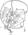
- FIG. 1 is a top perspective view of an HMD 10 mounted on a helmet 12 for projecting imagery to the left and right eyes of a pilot.
- the imagery projected to the left and right eyes can be identical (biocular), or it can have stereo disparity (binocular).
- 1024 by 1024 digital color images are used, with each color image frame for the left and right eyes having separate red, green and blue pixelated intensity patterns.
- the invention is also applicable to gray scale or single color images of arbitrary dimensions.
- a computer image generator 14 produces successive scan lines for left and right color digital images 16 and 18 respectively at a given rate, preferably within a range of fifty to seventy-two images per second, and transmits modulation signals for the red, green and blue (RGB) intensity patterns simultaneously via leads 20a-20c and 22a-22c to left and right RGB light emitting diode (LED) arrays 24a-24c and 26a-26c.
- the RGB arrays are stacked, with the red array on the top and the blue array on the bottom.
- the respective arrays in the left and right optical channels each include 1024 LEDs 28a-28c and 30a-30c, and form a complete row or scan line of the color digital image.
- the left and right LED arrays emit luminance patterns 32a-32c and 34a-34c respectively in accordance with the successive intensity patterns of the image scan lines, and can be addressed sequentially to produce a raster-scanned image or in parallel to project each image a line at a time.
- a fiber optic ribbon can used in place of the LEDs to project the luminance patterns.
- the ribbon is connected from the HMD to a laser, LED or CRT line modulator off the helmet.
- Left and right relay lenses 36 and 38 are disposed at their focal length, e.g. 25 mm, from the LED arrays, and collimate the light for the respective luminance patterns.
- a common drive motor 39 rotates left and right faceted drum mirrors 40 and 42 at a rate synchronized to the modulation rate of the LEDs to deflect the collimated luminance patterns back through the relay lens.
- the lenses 36 and 38 focus the patterns onto successive scan lines on the back side of left and right back projection screens 44 and 46.
- a complete color image is projected onto the respective screens by each mirror facet by rotating the drum mirrors in synchronism with the modulation rate of the LEDs, so that each successive horizontal image line is deflected vertically relative to the preceeding line.
- a complete frame is projected as a series of vertically spaced image lines.
- a mirror with 12 facets rotates at 5 revolutions per second to match the 60 hz frame rate.
- single mirror galvanometers can be used to scan the images. The mirrors oscillate back and forth, but usually only scan the image in one direction.
- the back projection screens 44 and 46 are positioned at the focal lengths of the lenses 36 and 38 beneath the stacked LED arrays 24a-24c and 26a-26c, so that if light were emitted simultaneously from the RGB arrays for coincident scan lines, it would be deflected onto three separate scan lines on the back projection screens, as shown in FIG. 2.
- the modulation of the red LEDs is time delayed and the modulation of the blue LEDs is time advanced.
- the back projection screens 44 and 46 emit color luminance patterns 48 and 50 in accordance with the red, green and blue luminance patterns incident on their back sides.
- the luminance patterns 48 and 50 are deflected off folding mirrors 52 and 54 through relay lenses 56 and 57 (details of which are shown in FIG. 6) to a visor 58.
- the relay lenses and visor collimate the divergent light from the back projection screens and deflect the images to the left and right eyes.
- Left and right housing structures 60 and 62 hold the relay lens, LED arrays and back projection screen for the respective optical channels so that they are orientated along parallel left and right central optical axes 64 and 66.
- the LED arrays and projection screens are centered on and perpendicular to the respective central optical axes, and are parallel to the rotation axes of the drum mirrors.
- a double threaded screw 68 connects the housing structures, which are arranged to slide along the helmet parallel to the screw axis.
- the screw is used to adjust the spacing between the optical channels by moving them closer together or farther apart, while holding them parallel to each other. This accommodates the IPD of the pilot without changing the respective optical paths, and therefore does not induce any distortion.
- the screw is manually adjusted for the individual pilot until a test pattern comes into view.
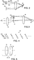
- FIG. 3 is a schematic diagram of one of the optical channels, and illustrates the light propagation for a single red LED.
- Light is typically emitted from the LED 28a along an angle of 180°, and a portion of the light propagates through relay lens 36, shown schematically as a simple convex lens having a focal length of 25 mm.
- the relay lens collimates the light, and a portion of the collimated light deflects off the drum mirror 40.
- the height of the mirror's facets and the diameter of the relay lens determines the angle of emitted light captured by the lens and deflected by the mirror.
- the captured angle must be at least ⁇ d radians, where ⁇ is the wavelength of the emitted light and d is the spacing between the LEDs.
- the ratio ⁇ d is Sparrows resolution limit for resolving point sources.
- the red LEDs have a spacing of 8 microns and a wavelength of 0.62 microns for a minimum angle of approximately 0.08 radians, or 4.4 degrees.
- the height of the mirror and the lens diameter are preferably chosen to capture the minimum necessary angle of light, to minimize the weight of the lens, drum mirror and the drive motor.
- the collimated light is deflected back through the relay lens 36, so that the lens focuses the light onto a single column in successive rows on the back projection screen 44.
- the wearer's eyes have a movement range (h) of ⁇ 7.5 mm over which projected images are visible.
- the movement can be attributed to the movement of the pupil or to slight shifts in the helmet.
- the images can be projected directly from the mirror to the visor but the range h would be only 1.9 mm, which is insufficient for practical displays. Instead, the design captures the minimum angle necessary to resolve the individual LEDs to limit the helmet's weight, and uses the back projection screens to increase the viewing range of the displayed images.
- FIG. 4 is a diagram of a staggered array 69 of LEDs representative of arrays 24a-24c and 26a-26c. If the LEDs were disposed in a single row, they would have to be spaced apart to avoid electrically shorting adjacent LEDs. However, the spacing causes gaps in the projected images. Therefore, the LEDs for a given array are staggered in four rows 69a-69d of 256 LEDs each to eliminate gaps in the projected imagery. If the staggered LEDs were simultaneously projected they would form a non-contiguous array of 1024 LEDs on four separate rows. To correct for the spacing between the rows so that the staggered LED array projects a linear scan line on the back projection screen, the modulation signals to the staggered rows are delayed in a manner similar to the compensation for the separate RGB arrays.
- FIG. 5 is a diagram of a particular design for relay lenses 36 and 38 in the respective optical channels.
- the relay lens is a complex lens with 3 lens elements 70, 72 and 74 that collimate the divergent luminance patterns projected by the LED arrays, and focus the deflected patterns onto the back of the projection screens.
- the radius of curvature, lens thickness, and glass type are selected in accordance with the desired focal length for the relay lens, and the configuration of the optical channel. Alternative designs and number of elements are possible.
- FIG. 5 is a diagram of a particular design for relay lenses 56 and 57 for the visor optics.
- Each lens comprises ten elements (76-94) of varying configurations.
- the lens complexity is a result of focusing the three colors at infinity, i.e. collimating the colors, and having the lens pupils coincide with the location of the pilot's eyes for each field of view.
- Light projected from the back projection screens 44 and 46 propagates through the lens elements and deflects off visor 58 onto the pilot's left and right eyes.
- the specific radius of curvature, lens thickness and glass type for each of the ten lens elements is determined by the physical dimension of the helmet and the desired size of the displayed image. Alternative lens configurations are also applicable.
- the HMD uses an array of light sources that form a complete scan line of the display image, which eliminates one of the scanning mirrors and its drive motor, and reduces the weight of the HMD.
- the independent and parallel left and right optical channels are easily adjustable to accomodate each pilot's IPD without distorting the image or requiring electronic compensation of the image.
Landscapes
- Physics & Mathematics (AREA)
- Optics & Photonics (AREA)
- General Physics & Mathematics (AREA)
- Engineering & Computer Science (AREA)
- Multimedia (AREA)
- Signal Processing (AREA)
- Devices For Indicating Variable Information By Combining Individual Elements (AREA)
Applications Claiming Priority (2)
| Application Number | Priority Date | Filing Date | Title |
|---|---|---|---|
| US26150994A | 1994-06-17 | 1994-06-17 | |
| US261509 | 1994-06-17 |
Publications (2)
| Publication Number | Publication Date |
|---|---|
| EP0687933A2 true EP0687933A2 (fr) | 1995-12-20 |
| EP0687933A3 EP0687933A3 (fr) | 1997-10-22 |
Family
ID=22993626
Family Applications (1)
| Application Number | Title | Priority Date | Filing Date |
|---|---|---|---|
| EP95303519A Ceased EP0687933A3 (fr) | 1994-06-17 | 1995-05-24 | Dispositif d'affichage en couleur monté sur un casque |
Country Status (7)
| Country | Link |
|---|---|
| US (1) | US5612708A (fr) |
| EP (1) | EP0687933A3 (fr) |
| JP (1) | JP2650878B2 (fr) |
| KR (1) | KR0181726B1 (fr) |
| CA (1) | CA2149565C (fr) |
| IL (1) | IL113758A (fr) |
| TW (1) | TW303064U (fr) |
Cited By (7)
| Publication number | Priority date | Publication date | Assignee | Title |
|---|---|---|---|---|
| EP0773456A3 (fr) * | 1995-11-09 | 1997-07-30 | Sharp Kk | Lentille grossissante et appareil d'affichage |
| EP0834760A2 (fr) * | 1996-10-07 | 1998-04-08 | HE HOLDINGS, INC. dba HUGHES ELECTRONICS | Projecteur monté sur la tête |
| GB2336265A (en) * | 1998-04-04 | 1999-10-13 | Marconi Electronic Syst Ltd | Optically scanned head-mounted display |
| WO2007080405A1 (fr) * | 2006-01-13 | 2007-07-19 | Stereonics Limited | Dispositif de verification d'alignement a reglage interoculaire |
| WO2013093510A3 (fr) * | 2011-12-23 | 2013-11-07 | Prp Optoelectronics Limited | Système d'affichage par projection |
| WO2019139757A1 (fr) * | 2018-01-12 | 2019-07-18 | Microsoft Technology Licensing, Llc | Lasers rvb à multiplexage géométrique dans un système d'affichage mems à balayage pour hmds |
| WO2023110168A1 (fr) * | 2021-12-16 | 2023-06-22 | Gixel GmbH | Système de visiocasque pour afficher une image virtuelle avec une efficacité améliorée |
Families Citing this family (32)
| Publication number | Priority date | Publication date | Assignee | Title |
|---|---|---|---|---|
| TW308647B (fr) * | 1994-12-02 | 1997-06-21 | Hitachi Ltd | |
| US5748164A (en) | 1994-12-22 | 1998-05-05 | Displaytech, Inc. | Active matrix liquid crystal image generator |
| US5808800A (en) * | 1994-12-22 | 1998-09-15 | Displaytech, Inc. | Optics arrangements including light source arrangements for an active matrix liquid crystal image generator |
| US6137525A (en) * | 1997-02-19 | 2000-10-24 | Lg Electronics Inc. | Personal data communication apparatus |
| US6271808B1 (en) * | 1998-06-05 | 2001-08-07 | Silicon Light Machines | Stereo head mounted display using a single display device |
| US6113243A (en) * | 1998-06-19 | 2000-09-05 | Saul; James D. | Driver information lights |
| FR2793322B1 (fr) * | 1999-05-07 | 2002-07-26 | Sextant Avionique | Dispositif optronique muni d'un miroir de mise au point pour projection sur visiere |
| SE516881C2 (sv) | 1999-05-31 | 2002-03-19 | Saabtech Electronics Ab | Förfarande och anordning för överlagring av en bild på en direkt omvärldsbild för att presenteras en observatör |
| US6724354B1 (en) * | 1999-06-21 | 2004-04-20 | The Microoptical Corporation | Illumination systems for eyeglass and facemask display systems |
| EP1121959A1 (fr) * | 2000-02-01 | 2001-08-08 | Optrel Ag | Dispositif de sûreté d'urgence pour aéronef |
| US6899539B1 (en) | 2000-02-17 | 2005-05-31 | Exponent, Inc. | Infantry wearable information and weapon system |
| US6292953B1 (en) * | 2000-08-17 | 2001-09-25 | Gentex Corporation | Interchangeable latch system |
| US20030090439A1 (en) * | 2001-09-07 | 2003-05-15 | Spitzer Mark B. | Light weight, compact, remountable face-supported electronic display |
| US7034811B2 (en) | 2002-08-07 | 2006-04-25 | Hewlett-Packard Development Company, L.P. | Image display system and method |
| US7030894B2 (en) * | 2002-08-07 | 2006-04-18 | Hewlett-Packard Development Company, L.P. | Image display system and method |
| US20070089215A1 (en) * | 2005-10-26 | 2007-04-26 | Lightswitch Safety Systems, Inc. | Bifocal magnifier plate for use in welding |
| US7595933B2 (en) * | 2006-10-13 | 2009-09-29 | Apple Inc. | Head mounted display system |
| BRPI0808123A2 (pt) * | 2007-02-28 | 2014-06-17 | L 3 Comm Corp | Sistemas e métodos para ajudar na consciência situacional de pilotos |
| WO2009126264A2 (fr) * | 2008-04-06 | 2009-10-15 | David Chaum | Système de projection proximale d'image |
| US8120857B2 (en) * | 2008-10-15 | 2012-02-21 | Gentex Corporation | Apparatus and method for mounting and calibrating a helmet-mounted display |
| WO2010141870A1 (fr) * | 2009-06-04 | 2010-12-09 | Kopin Corporation | Processeur vidéo 3d intégré à une paire de lunettes à afficheur |
| WO2011060347A1 (fr) * | 2009-11-13 | 2011-05-19 | Kopin Corporation | Procédé pour la commande de lunettes binoculaires 3d à partir de flux video standard |
| WO2011084895A1 (fr) | 2010-01-08 | 2011-07-14 | Kopin Corporation | Lunettes vidéo pour jeux de téléphone intelligent |
| GB2515517A (en) * | 2013-06-26 | 2014-12-31 | Prp Optoelectronics Ltd | A projection display system |
| CN103630121B (zh) * | 2013-07-16 | 2017-02-08 | 中国人民解放军信息工程大学 | 一种基于最佳扫描行快速定位的线阵影像微分纠正方法 |
| WO2016022984A1 (fr) * | 2014-08-08 | 2016-02-11 | Fusar Technologies, Inc. | Système de casque et procédés |
| KR102295452B1 (ko) | 2014-10-24 | 2021-08-27 | 이매진 코퍼레이션 | 마이크로디스플레이 기반 몰입형 헤드셋 |
| JP2016197145A (ja) * | 2015-04-02 | 2016-11-24 | 株式会社東芝 | 画像処理装置および画像表示装置 |
| KR102200948B1 (ko) | 2017-11-14 | 2021-01-11 | 엠티스코퍼레이션(주) | 헬멧 탈착용 디스플레이장치 |
| US20220121027A1 (en) | 2019-02-01 | 2022-04-21 | Magic Leap, Inc. | Display system having 1-dimensional pixel array with scanning mirror |
| CN115552315A (zh) * | 2020-03-16 | 2022-12-30 | 奥罗拉科技公司 | 用于扫描微led阵列的显示器驱动器ic(ddic)背板 |
| GB2623760A (en) * | 2022-10-24 | 2024-05-01 | Newell Neil | Display |
Citations (2)
| Publication number | Priority date | Publication date | Assignee | Title |
|---|---|---|---|---|
| US5091719A (en) | 1989-12-26 | 1992-02-25 | General Electric Company | Helmet display |
| US5166778A (en) | 1991-09-05 | 1992-11-24 | General Electric Company | Single-lens color video stereoscopic helmet mountable display |
Family Cites Families (5)
| Publication number | Priority date | Publication date | Assignee | Title |
|---|---|---|---|---|
| US4449787A (en) * | 1980-07-22 | 1984-05-22 | International Telephone And Telegraph Corporation | Night vision imaging system adapted for helmet mounting |
| US5003300A (en) * | 1987-07-27 | 1991-03-26 | Reflection Technology, Inc. | Head mounted display for miniature video display system |
| US4897715A (en) * | 1988-10-31 | 1990-01-30 | General Electric Company | Helmet display |
| US5040058A (en) * | 1989-12-26 | 1991-08-13 | General Electric Company | Raster graphic helmet mountable display |
| WO1992018917A1 (fr) * | 1991-04-19 | 1992-10-29 | The Commonwealth Of Australia | Systeme modulaire de gestion de frequences |
-
1995
- 1995-05-16 CA CA002149565A patent/CA2149565C/fr not_active Expired - Lifetime
- 1995-05-17 IL IL11375895A patent/IL113758A/en not_active IP Right Cessation
- 1995-05-24 EP EP95303519A patent/EP0687933A3/fr not_active Ceased
- 1995-06-14 TW TW085211151U patent/TW303064U/zh unknown
- 1995-06-16 KR KR1019950015963A patent/KR0181726B1/ko not_active IP Right Cessation
- 1995-06-16 JP JP7150478A patent/JP2650878B2/ja not_active Expired - Lifetime
-
1996
- 1996-04-22 US US08/636,025 patent/US5612708A/en not_active Expired - Lifetime
Patent Citations (2)
| Publication number | Priority date | Publication date | Assignee | Title |
|---|---|---|---|---|
| US5091719A (en) | 1989-12-26 | 1992-02-25 | General Electric Company | Helmet display |
| US5166778A (en) | 1991-09-05 | 1992-11-24 | General Electric Company | Single-lens color video stereoscopic helmet mountable display |
Cited By (11)
| Publication number | Priority date | Publication date | Assignee | Title |
|---|---|---|---|---|
| EP0773456A3 (fr) * | 1995-11-09 | 1997-07-30 | Sharp Kk | Lentille grossissante et appareil d'affichage |
| US5748375A (en) * | 1995-11-09 | 1998-05-05 | Sharp Kabushiki Kaisha | Magnifying lens and display apparatus |
| EP0834760A2 (fr) * | 1996-10-07 | 1998-04-08 | HE HOLDINGS, INC. dba HUGHES ELECTRONICS | Projecteur monté sur la tête |
| EP0834760A3 (fr) * | 1996-10-07 | 1999-03-03 | Raytheon Company | Projecteur monté sur la tête |
| GB2336265A (en) * | 1998-04-04 | 1999-10-13 | Marconi Electronic Syst Ltd | Optically scanned head-mounted display |
| US6369779B1 (en) | 1998-04-04 | 2002-04-09 | Bae Systems Electronics Limited | Display arrangements |
| WO2007080405A1 (fr) * | 2006-01-13 | 2007-07-19 | Stereonics Limited | Dispositif de verification d'alignement a reglage interoculaire |
| WO2013093510A3 (fr) * | 2011-12-23 | 2013-11-07 | Prp Optoelectronics Limited | Système d'affichage par projection |
| WO2019139757A1 (fr) * | 2018-01-12 | 2019-07-18 | Microsoft Technology Licensing, Llc | Lasers rvb à multiplexage géométrique dans un système d'affichage mems à balayage pour hmds |
| US10620430B2 (en) | 2018-01-12 | 2020-04-14 | Microsoft Technology Licensing, Llc | Geometrically multiplexed RGB lasers in a scanning MEMS display system for HMDS |
| WO2023110168A1 (fr) * | 2021-12-16 | 2023-06-22 | Gixel GmbH | Système de visiocasque pour afficher une image virtuelle avec une efficacité améliorée |
Also Published As
| Publication number | Publication date |
|---|---|
| JPH08171072A (ja) | 1996-07-02 |
| KR0181726B1 (ko) | 1999-05-15 |
| CA2149565C (fr) | 2000-02-01 |
| TW303064U (en) | 1997-04-11 |
| KR960001799A (ko) | 1996-01-25 |
| US5612708A (en) | 1997-03-18 |
| IL113758A (en) | 1998-10-30 |
| IL113758A0 (en) | 1995-08-31 |
| CA2149565A1 (fr) | 1995-12-18 |
| EP0687933A3 (fr) | 1997-10-22 |
| JP2650878B2 (ja) | 1997-09-10 |
Similar Documents
| Publication | Publication Date | Title |
|---|---|---|
| US5612708A (en) | Color helmet mountable display | |
| EP3384337B1 (fr) | Système de projection d'images | |
| CA2220283C (fr) | Afficheur retinien virtuel a source ponctuelle par fibre optique | |
| JP3435160B2 (ja) | 仮想網膜表示装置 | |
| US6008781A (en) | Virtual retinal display | |
| CA2217118C (fr) | Projecteur monte sur la tete | |
| EP0435523A2 (fr) | Afficheur de casque | |
| US5657165A (en) | Apparatus and method for generating full-color images using two light sources | |
| US20060033992A1 (en) | Advanced integrated scanning focal immersive visual display | |
| US20050030308A1 (en) | Three-dimensional display method and device therefor | |
| WO1994009472A9 (fr) | Production d'images virtuelles percues par la retine | |
| US20030197933A1 (en) | Image input apparatus and image display apparatus | |
| CN107561701B (zh) | 近眼显示系统、虚拟现实设备及增强现实设备 | |
| JP2007018013A (ja) | 光ディスプレイシステム及び方法 | |
| WO2018001325A1 (fr) | Système d'affichage proche de l'oeil, dispositif de réalité virtuelle et dispositif à réalité augmentée | |
| CN107562181B (zh) | 近眼显示系统、虚拟现实设备及增强现实设备 | |
| KR100275387B1 (ko) | 가상현실표시장치 |
Legal Events
| Date | Code | Title | Description |
|---|---|---|---|
| PUAI | Public reference made under article 153(3) epc to a published international application that has entered the european phase |
Free format text: ORIGINAL CODE: 0009012 |
|
| AK | Designated contracting states |
Kind code of ref document: A2 Designated state(s): DE FR GB SE |
|
| PUAL | Search report despatched |
Free format text: ORIGINAL CODE: 0009013 |
|
| AK | Designated contracting states |
Kind code of ref document: A3 Designated state(s): DE FR GB SE |
|
| 17P | Request for examination filed |
Effective date: 19980403 |
|
| RAP1 | Party data changed (applicant data changed or rights of an application transferred) |
Owner name: RAYTHEON COMPANY |
|
| 17Q | First examination report despatched |
Effective date: 20000428 |
|
| GRAG | Despatch of communication of intention to grant |
Free format text: ORIGINAL CODE: EPIDOS AGRA |
|
| STAA | Information on the status of an ep patent application or granted ep patent |
Free format text: STATUS: THE APPLICATION HAS BEEN REFUSED |
|
| 18R | Application refused |
Effective date: 20020224 |