EP0687850B1 - Gaine d'isolation thermique pour canalisation et son procédé de fabrication - Google Patents
Gaine d'isolation thermique pour canalisation et son procédé de fabrication Download PDFInfo
- Publication number
- EP0687850B1 EP0687850B1 EP94401367A EP94401367A EP0687850B1 EP 0687850 B1 EP0687850 B1 EP 0687850B1 EP 94401367 A EP94401367 A EP 94401367A EP 94401367 A EP94401367 A EP 94401367A EP 0687850 B1 EP0687850 B1 EP 0687850B1
- Authority
- EP
- European Patent Office
- Prior art keywords
- lagging
- thermally insulating
- tube
- sheath
- elastomer
- Prior art date
- Legal status (The legal status is an assumption and is not a legal conclusion. Google has not performed a legal analysis and makes no representation as to the accuracy of the status listed.)
- Expired - Lifetime
Links
- 238000004519 manufacturing process Methods 0.000 title claims description 18
- 238000000034 method Methods 0.000 title claims description 8
- 229920002379 silicone rubber Polymers 0.000 claims description 19
- 239000004945 silicone rubber Substances 0.000 claims description 19
- 230000002787 reinforcement Effects 0.000 claims description 16
- 239000000919 ceramic Substances 0.000 claims description 15
- 239000004744 fabric Substances 0.000 claims description 15
- 239000011810 insulating material Substances 0.000 claims description 15
- 229920001971 elastomer Polymers 0.000 claims description 14
- 239000000806 elastomer Substances 0.000 claims description 14
- 239000004753 textile Substances 0.000 claims description 14
- 239000000463 material Substances 0.000 claims description 13
- 238000004804 winding Methods 0.000 claims description 12
- 239000013521 mastic Substances 0.000 claims description 9
- 229920001296 polysiloxane Polymers 0.000 claims description 9
- 239000006260 foam Substances 0.000 claims description 7
- 235000011837 pasties Nutrition 0.000 claims description 4
- 239000012815 thermoplastic material Substances 0.000 claims description 4
- 238000004132 cross linking Methods 0.000 claims description 3
- 239000011152 fibreglass Substances 0.000 claims 4
- 238000009413 insulation Methods 0.000 description 15
- 239000011248 coating agent Substances 0.000 description 13
- 238000000576 coating method Methods 0.000 description 13
- 239000013536 elastomeric material Substances 0.000 description 9
- 241000735470 Juncus Species 0.000 description 8
- 241001639412 Verres Species 0.000 description 6
- 239000011521 glass Substances 0.000 description 5
- 238000004073 vulcanization Methods 0.000 description 5
- 239000004698 Polyethylene Substances 0.000 description 4
- 238000009434 installation Methods 0.000 description 4
- -1 polyethylene Polymers 0.000 description 4
- 229920000573 polyethylene Polymers 0.000 description 4
- 210000001519 tissue Anatomy 0.000 description 4
- KWGRBVOPPLSCSI-WPRPVWTQSA-N (-)-ephedrine Chemical compound CN[C@@H](C)[C@H](O)C1=CC=CC=C1 KWGRBVOPPLSCSI-WPRPVWTQSA-N 0.000 description 3
- WYTGDNHDOZPMIW-RCBQFDQVSA-N alstonine Natural products C1=CC2=C3C=CC=CC3=NC2=C2N1C[C@H]1[C@H](C)OC=C(C(=O)OC)[C@H]1C2 WYTGDNHDOZPMIW-RCBQFDQVSA-N 0.000 description 3
- 230000000694 effects Effects 0.000 description 3
- 239000003365 glass fiber Substances 0.000 description 3
- 229920001195 polyisoprene Polymers 0.000 description 3
- 239000011347 resin Substances 0.000 description 3
- 229920005989 resin Polymers 0.000 description 3
- 241000195940 Bryophyta Species 0.000 description 2
- RRHGJUQNOFWUDK-UHFFFAOYSA-N Isoprene Chemical compound CC(=C)C=C RRHGJUQNOFWUDK-UHFFFAOYSA-N 0.000 description 2
- 240000008042 Zea mays Species 0.000 description 2
- 239000000853 adhesive Substances 0.000 description 2
- 230000001070 adhesive effect Effects 0.000 description 2
- 238000005520 cutting process Methods 0.000 description 2
- 239000007789 gas Substances 0.000 description 2
- 238000011065 in-situ storage Methods 0.000 description 2
- 235000011929 mousse Nutrition 0.000 description 2
- 239000002984 plastic foam Substances 0.000 description 2
- 239000000565 sealant Substances 0.000 description 2
- ZAMOUSCENKQFHK-UHFFFAOYSA-N Chlorine atom Chemical compound [Cl] ZAMOUSCENKQFHK-UHFFFAOYSA-N 0.000 description 1
- 241001080024 Telles Species 0.000 description 1
- 239000011324 bead Substances 0.000 description 1
- 210000004027 cell Anatomy 0.000 description 1
- 229910052801 chlorine Inorganic materials 0.000 description 1
- 239000000460 chlorine Substances 0.000 description 1
- 239000000470 constituent Substances 0.000 description 1
- 238000004090 dissolution Methods 0.000 description 1
- 229940082150 encore Drugs 0.000 description 1
- 239000000835 fiber Substances 0.000 description 1
- 239000012530 fluid Substances 0.000 description 1
- 239000006261 foam material Substances 0.000 description 1
- 239000003517 fume Substances 0.000 description 1
- 235000021189 garnishes Nutrition 0.000 description 1
- 238000005304 joining Methods 0.000 description 1
- 239000000314 lubricant Substances 0.000 description 1
- 238000012423 maintenance Methods 0.000 description 1
- 230000000873 masking effect Effects 0.000 description 1
- 239000011159 matrix material Substances 0.000 description 1
- 231100000252 nontoxic Toxicity 0.000 description 1
- 230000003000 nontoxic effect Effects 0.000 description 1
- 230000000149 penetrating effect Effects 0.000 description 1
- 239000004033 plastic Substances 0.000 description 1
- 229920003023 plastic Polymers 0.000 description 1
- 230000003014 reinforcing effect Effects 0.000 description 1
- QEVHRUUCFGRFIF-MDEJGZGSSA-N reserpine Chemical compound O([C@H]1[C@@H]([C@H]([C@H]2C[C@@H]3C4=C(C5=CC=C(OC)C=C5N4)CCN3C[C@H]2C1)C(=O)OC)OC)C(=O)C1=CC(OC)=C(OC)C(OC)=C1 QEVHRUUCFGRFIF-MDEJGZGSSA-N 0.000 description 1
- 230000035939 shock Effects 0.000 description 1
- 239000004590 silicone sealant Substances 0.000 description 1
- 231100000331 toxic Toxicity 0.000 description 1
- 230000002588 toxic effect Effects 0.000 description 1
Images


Classifications
-
- F—MECHANICAL ENGINEERING; LIGHTING; HEATING; WEAPONS; BLASTING
- F16—ENGINEERING ELEMENTS AND UNITS; GENERAL MEASURES FOR PRODUCING AND MAINTAINING EFFECTIVE FUNCTIONING OF MACHINES OR INSTALLATIONS; THERMAL INSULATION IN GENERAL
- F16L—PIPES; JOINTS OR FITTINGS FOR PIPES; SUPPORTS FOR PIPES, CABLES OR PROTECTIVE TUBING; MEANS FOR THERMAL INSULATION IN GENERAL
- F16L59/00—Thermal insulation in general
- F16L59/02—Shape or form of insulating materials, with or without coverings integral with the insulating materials
- F16L59/021—Shape or form of insulating materials, with or without coverings integral with the insulating materials comprising a single piece or sleeve, e.g. split sleeves; consisting of two half sleeves; comprising more than two segments
- F16L59/022—Shape or form of insulating materials, with or without coverings integral with the insulating materials comprising a single piece or sleeve, e.g. split sleeves; consisting of two half sleeves; comprising more than two segments with a single slit
-
- F—MECHANICAL ENGINEERING; LIGHTING; HEATING; WEAPONS; BLASTING
- F16—ENGINEERING ELEMENTS AND UNITS; GENERAL MEASURES FOR PRODUCING AND MAINTAINING EFFECTIVE FUNCTIONING OF MACHINES OR INSTALLATIONS; THERMAL INSULATION IN GENERAL
- F16L—PIPES; JOINTS OR FITTINGS FOR PIPES; SUPPORTS FOR PIPES, CABLES OR PROTECTIVE TUBING; MEANS FOR THERMAL INSULATION IN GENERAL
- F16L59/00—Thermal insulation in general
- F16L59/06—Arrangements using an air layer or vacuum
Definitions
- the invention relates to an insulation sheath thermal for pipeline and its method of manufacturing.
- the pipes or conduits in which circulate a fluid at a temperature different from that of ambient environment are generally provided with sheaths surrounding and which have a double or triple role namely, that of thermal insulation, that of protection of said conduits or pipes, but also that of protection of personnel who may be required to circulate at neighborhood of these pipes or conduits when they are placed at or above ground or floor level of a man.
- thermal insulation sheath for flexible pipe which can therefore be installed on the pipe or pipeline which it must equip by marrying the form, often complex, of said pipe or pipeline.
- thermal insulation sheath for pipeline which has good mechanical resistance qualities, of which the dimensions for the pipe or pipeline that her team is not greater than that of known devices and which, moreover, has insulation qualities at least equal, if not better than those of previous devices.
- an object of the invention to provide a method of manufacturing such a sheath.
- a thermal insulation sheath for pipeline includes a tube of material of the type compact and flexible elastomer, intended to come into contact of the pipe to be insulated, and which is conformed on its internal surface following a helical rib which house a filled "coil” between its adjacent turns air or gas when the sheath is placed on said pipeline by enclosing it.
- Such a sheath is notably disclosed by the document US-A-3,060,069, and the tube which encloses the pipe can also include a textile grid support and reinforcement.
- the helical rib is obtained by deforming the tube over its entire thickness to form undulations.
- the thermal insulation sheath according to the invention is characterized in that the rib helical is formed on the internal surface of the tube, in that the textile grid or retaining fabric is type with large or large bi-elastic deformation deformability in two orthogonal directions, and in this that the reinforcement is in the form of a coil helical mounted in the pitch of the turns of the rib.
- the reinforcement can advantageously be made up by a rod of thermoplastic material to give the sheath good mechanical strength, in particular of crush resistance.
- a flexible product is thus obtained, which can be bent to about three times its diameter and which can be threaded on pipes or conduits that it must equip, even when these have a shape complex, so that hard work is removed, - and which cannot be carried out on site -, "swaddling" pipes using glass fiber mats and of resin or the like.
- the layer of thermally insulating material is of the ceramic paper or similar type.
- the layer of thermally insulating material is a putty, in the form relatively compact foam, for example silicone and ceramic, which can be easily cut without deteriorate.
- the innermost surface of the rib which is at the contact of the pipe on which the sheath-, is covered with a fabric, of the type significant bi-elastic deformation in two directions orthogonal and which is intended to facilitate the implementation place of the sheath on the pipe by an effect of "slip".
- the invention provides for splitting said sheath longitudinally and to provide the edges with the slot of a closure means (of the slide type, or with mutual fastening bands by velvet / hooks or similar).
- the invention advantageously and in addition provides shape a lip at the same time as the coating external, lip which can be folded down on said means of closure to hide it after fitting the sheath on the pipeline.
- the invention contemplates using, preferably, a silicone rubber as a material tube, outer coating and intermediate films when these are present.
- the sheath When the sheath is of the split type longitudinally it is either manufactured as described above in steps a) a h) or a) to i) and is then cut along one of its generators, or manufactured as described above during steps a) -b ') at g ') these steps being followed by cutting the blank with the braid covering the putty thermally insulating along one of its generators, then placing on the edges of the slot closing elements before the external coating of fitted elastomeric material, if applicable if necessary, a lip that can be folded down to hide the closure and vulcanization elements of the assembly.
- Such a sheath 10 is flexible, can be shaped according to radii of curvature of the order of three times its diameter and, when reported on a pipe, provides a role of thermal insulation to both by its constituents and by air or gas locked in the throat or "serpentine" 14.
- a sheath according to the invention, 10 is put in place on a pipe C which it is intended to equip simply by threading the sheath on the pipe which can be fixed at one of its ends to a flange B 1 then, after fitting the sheath, at its other end by a flange B 2 , the positioning of the sheath 10 on the pipe C being facilitated by bringing a film to the internal surface 25 of the rib 12 lubricant or the like.
- a sheath according to the invention has excellent crush resistance, plays perfectly its role of thermal insulation, does not transmit no noise, and introduces a significant fire delay in fire. It thus allows, as shown on the Figure 9, to equip the entire piping system or pipes of a fixed or mobile installation, for example example that of a ship, without having to dismantle and treat said pipelines or pipes in the factory as was necessary until now.
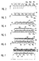
- the invention proposes a method according to which a profiled element 35, the cross section of which is that of the groove 14 and which is placed on said mandrel in a helical winding with tight turns 36 1 , 36 2 , etc.
- a profiled element 35 advantageously made of a thermoplastic material, such as PVC or polyethylene
- a pasty elastomeric material such as silicone rubber which, penetrating into the spaces limited by the mandrel M and the turns 36, forms the blank of the internal tube 11 of the sheath.
- the assembly thus constituted is then vulcanized, in the usual way, then the section 35 is extract it, simply by pulling on its end free, as shown on the right side of the figure 7 where it is no longer apparent on the first part of sheath, while still in contact with the mandrel M on the left part of this same figure.
- a sheath according to the invention Since a sheath according to the invention has a sufficient "spring" effect when it is split longitudinally, as shown at 30 in FIG. 9, it can also be placed on a pipe like C 1 , ends cannot be separated from the flanges which hold it in place, by overlapping the pipe by the split sheath then by joining the two edges of the slot for example using an appropriate adhesive means.
- the invention proposes another realization of a sheath according to the invention and an alternative embodiment of the method which has just been described.
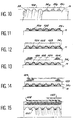
- the invention provides a variant of the process described above according to which we first report on the mandrel M, FIG. 10, the profiled element 35, the straight section is that of throat 111 taped by the 100 fabric placed on this profiled element and which is held in place by rod 102, Figure 11.
- profile 35 is extracted and the sheath removed from mandrel M.
- the element closure 106 is not a zipper, but a velvet / hook (Velcro) type closure or again, in another variant and as shown on the Figure 18, a clip-like member, 120, which encloses beads 121 and 122 formed on the split edges of the sheath, which comprises, as in the production of Figures 16 and 17, a lip 123 suitable for masking said closing element.
- a clip-like member, 120 which encloses beads 121 and 122 formed on the split edges of the sheath, which comprises, as in the production of Figures 16 and 17, a lip 123 suitable for masking said closing element.
- An insulating sheath 10 such as described above with reference to a mandrel M of 50 mm external diameter a sectioned element 5 mm high trapezoidal straight, small base 2 mm and large 4 mm base wound in tight turns in steps of about 4 mm.
- a reinforcement 17 constituted by a round of polyethylene rigid with a diameter of 2.5 mm, which is rolled up in steps 4 mm and unlike the turns of the first profile.
- the coating external 21 in silicone rubber with a thickness of 2 mm is also in place before vulcanization of all.
- a sheath according to the invention resists temperatures of the order of 250 ° C, withstands shocks crush and can be bent to about 3 times its diameter.
- the sheath blank is then split longitudinally then, after placing a braid, a new layer of silicone rubber with a thickness between 1 and 2 mm, -supported, if applicable if necessary, of a tissue-, is then reported before vulcanization of the whole.
Landscapes
- Engineering & Computer Science (AREA)
- General Engineering & Computer Science (AREA)
- Mechanical Engineering (AREA)
- Laminated Bodies (AREA)
- Thermal Insulation (AREA)
- Moulding By Coating Moulds (AREA)
Description
- une tresse en fils de verre ; et
- une couche de matériau thermiquement isolant.
- la figure 1 est une vue en élévation, avec arrachement, d'une première forme de réalisation d'une gaine selon l'invention ;
- les figures 2 à 7 illustrent un procédé de fabrication d'une telle gaine ;
- les figures 8 et 9 illustrent des modes de mise en place d'une gaine selon l'invention sur des canalisations ;
- les figures 10 à 15 sont des vues analogues à celles des figures 2 à 7, mais pour une variante du procédé de fabrication ;
- la figure 16 est une vue schématique, en perspective, d'une gaine "fendue" selon l'invention ;
- la figure 17 en est une vue en coupe transversale, à plus grande échelle ;
- la figure 18 est une vue de détail d'une variante.
Claims (11)
- Gaíne d'isolation thermique pour canalisation, du type comprenant un tube (11, 103) destiné à venir au contact de la canalisation (C) à isoler suivant une nervure hélicoïdale (12) qui ménage entre ses spires adjacentes un "serpentin" (14, 111) rempli d'air ou de gaz lorsque la gaíne est mise en place sur ladite canalisation en l'enserrant, ledit tube (11, 103) étant constitué en un matériau du type élastomère compact et souple, et comprenant au moins une fine grille textile ou tissu de maintien (16, 100) et un renfort, caractérisée en ce que la nervure hélicoïdale (12) est ménagée sur la surface interne du tube (11, 103), en ce que la grille textile ou tissu de maintien est du type à déformation bi-élastique importante ou à grande déformabilité dans deux directions orthogonales, et en ce que le renfort (17, 102) est sous la forme d'un enroulement hélicoïdal monté dans le pas des spires de la nervure (12).
- Gaine d'isolation thermique selon la revendication 1, caractérisée en ce que le renfort (17, 102) est constitué par un jonc en matière thermoplastique.
- Gaine d'isolation thermique selon la revendication 1 ou 2, caractérisée en ce qu'elle comprend un revêtement externe (21, 105) d'élastomère, de préférence de caoutchouc silicone et, entre ledit revêtement externe et l'enroulement (17) assurant la tenue à l'écrasement, successivement et à partir du revêtement externe en direction de l'intérieur de la gaíne :une tresse en fils de verre (20, 104) ; etune couche de matériau thermiquement isolant (19, 103).
- Gaíne d'isolation thermique selon la revendication 3, caractérisée en ce que la couche de matériau thermiquement isolant (19) est du type papier de céramique ou analogue.
- Gaíne d'isolation thermique selon la revendication 3, caractérisée en ce que la couche de matériau thermiquement isolant (103) est un mastic, sous forme de mousse relativement compacte, de silicone et de céramique.
- Gaine d'isolation thermique selon l'une quelconque des revendications précédentes, caractérisée en ce qu'elle est fendue le long d'une de ses génératrices et en ce que les bords de la fente sont munis d'un moyen de fermeture (106).
- Gaine d'isolation thermique selon la revendication 6, caractérisée en ce qu'elle comprend en outre une lèvre (110) propre à être rabattue sur le moyen de fermeture (106) pour le masquer après mise en place de la gaíne sur une canalisation (C) qu'elle doit équiper.
- Procédé de fabrication d'une gaíne selon l'une quelconque des revendications précédentes, caractérisé en ce qu'il consiste :à disposer d'abord sur un mandrin (M) et suivant un enroulement hélicoïdal à spires serrées (36), un élément profilé (35) destiné à former le tube à rainure hélicoïdale de la gaíne ;à former une ébauche dudit tube à l'aide d'un matériau de type élastomère à l'état pâteux ;à rapporter une grille textile (16) sur la surface externe de l'ébauche du tube ;à rapporter sur la grille (16) un renfort (17) assurant la tenue à l'écrasement de la gaíne sous forme d'un enroulement hélicoïdal d'un jonc monté dans le pas des spires de l'élément profilé (35) ;à disposer successivement sur l'ébauche dudit tube ainsi garnie un matériau thermiquement isolant (19) et sur sa surface externe une tresse (20) ;à enfermer l'ensemble formé dans un revêtement (21) de matériau élastomère ;à procéder à la vulcanisation de l'ensemble ;à extraire ensuite l'élément profilé (35) ; età dégager la gaíne ainsi formée du mandrin (M).
- Procédé de fabrication d'une gaíne selon la revendication 8, caractérisé, en outre :en ce que l'on constitue le matériau thermiquement isolant (19) par un papier, -avantageusement un papier de céramique ou analogue-, avec interposition entre lui et l'enroulement hélicoïdal du jonc de renfort d'une tresse en fils de verre (20) ; eten ce que le matériau élastomère mis en oeuvre est un caoutchouc silicone.
- Procédé de fabrication d'une gaíne selon l'une quelconque des revendications 1 à 7, caractérisé en ce qu'il consiste :à disposer d'abord sur un mandrin (M) et suivant un enroulement hélicoïdal à spires serrées (36), un élément profilé (35) destiné à former le tube à nervure hélicoïdal de la gaíne ;à disposer sur l'élément profilé un tissu (100) à déformation bi-élastique importante dans deux directions orthogonales, posé en long avec léger recouvrement de ses bords ;à rapporter sur ce tissu (100) un renfort (102) assurant la tenue à l'écrasement de la gaíne sous la forme d'un enroulement hélicoïdal d'un jonc monté dans le pas des spires de l'élément profilé (35) ;à recouvrer le tissu et le jonc d'un film de matériau élastomère, avantageusement un caoutchouc silicone ;à rapporter sur ce film de matériau élastomère le matériau isolant (103) sous forme d'une mousse relativement compacte d'un mastic de silicone et de céramique ;à effectuer une réticulation de l'ensemble ;à disposer sur le mastic réticulé une tresse en fils de verre (104) ;à enfermer l'ensemble formé dans un revêtement de matériau élastomère, comme du caoutchouc silicone ;à effectuer une vulcanisation de l'ensemble ;à extraire ensuite l'élément profilé (35) mis en place au cours de la première étape et on dégage la gaine formée du mandrin.
- Procédé de fabrication d'une gaine du type fendue, par mise en oeuvre d'un procédé selon la revendication 10, caractérisé en ce qu'après dépôt de la tresse en fils de verre (104) on coupe l'ébauche le long d'une de ses génératrices, on met en place sur les bords de la fente des éléments de fermeture avant de rapporter le revêtement externe de matériau élastomère muni, le cas échéant, d'une lèvre (110) pouvant être rabattue pour masquer les éléments de fermeture (106) et on vulcanise l'ensemble.
Priority Applications (6)
| Application Number | Priority Date | Filing Date | Title |
|---|---|---|---|
| FR9303657A FR2703431B1 (fr) | 1993-03-30 | 1993-03-30 | Gaine d'isolation thermique pour canalisation et son procede de fabrication. |
| CA002135911A CA2135911A1 (fr) | 1993-03-30 | 1994-03-29 | Gaine d'isolation thermique pour canalisation et son procede de fabrication |
| PCT/FR1994/000348 WO1994023238A1 (fr) | 1993-03-30 | 1994-03-29 | Gaine d'isolation thermique pour canalisation et son procede de fabrication |
| DE1994612798 DE69412798T2 (de) | 1994-06-17 | 1994-06-17 | Thermisch isolierte Umhüllung für eine Rohrleitung und Verfahren zu ihrer Herstellung |
| EP94401367A EP0687850B1 (fr) | 1993-03-30 | 1994-06-17 | Gaine d'isolation thermique pour canalisation et son procédé de fabrication |
| AT94401367T ATE170278T1 (de) | 1994-06-17 | 1994-06-17 | Thermisch isolierte umhüllung für eine rohrleitung und verfahren zu ihrer herstellung |
Applications Claiming Priority (2)
| Application Number | Priority Date | Filing Date | Title |
|---|---|---|---|
| FR9303657A FR2703431B1 (fr) | 1993-03-30 | 1993-03-30 | Gaine d'isolation thermique pour canalisation et son procede de fabrication. |
| EP94401367A EP0687850B1 (fr) | 1993-03-30 | 1994-06-17 | Gaine d'isolation thermique pour canalisation et son procédé de fabrication |
Publications (2)
| Publication Number | Publication Date |
|---|---|
| EP0687850A1 EP0687850A1 (fr) | 1995-12-20 |
| EP0687850B1 true EP0687850B1 (fr) | 1998-08-26 |
Family
ID=26137505
Family Applications (1)
| Application Number | Title | Priority Date | Filing Date |
|---|---|---|---|
| EP94401367A Expired - Lifetime EP0687850B1 (fr) | 1993-03-30 | 1994-06-17 | Gaine d'isolation thermique pour canalisation et son procédé de fabrication |
Country Status (4)
| Country | Link |
|---|---|
| EP (1) | EP0687850B1 (fr) |
| CA (1) | CA2135911A1 (fr) |
| FR (1) | FR2703431B1 (fr) |
| WO (1) | WO1994023238A1 (fr) |
Cited By (1)
| Publication number | Priority date | Publication date | Assignee | Title |
|---|---|---|---|---|
| US7544890B2 (en) | 2005-11-22 | 2009-06-09 | Pratt & Whitney Canada Corp. | Insulated article and method of making same |
Families Citing this family (2)
| Publication number | Priority date | Publication date | Assignee | Title |
|---|---|---|---|---|
| FR2723420B1 (fr) * | 1994-08-02 | 1996-09-27 | Mr Ind | Tuyau souple a isolation renforcee |
| GB2365095A (en) * | 2000-07-29 | 2002-02-13 | Federal Mogul Technology Ltd | Flexible protective sleeve |
Family Cites Families (13)
| Publication number | Priority date | Publication date | Assignee | Title |
|---|---|---|---|---|
| GB719638A (en) * | 1951-12-01 | 1954-12-08 | Dunlop Rubber Co | Reinforced flexible tubing |
| US3275038A (en) * | 1959-06-26 | 1966-09-27 | Fred T Roberts & Company | Reinforced helically corrugated flexible hose |
| US3060069A (en) * | 1959-10-23 | 1962-10-23 | Fred E Sindars | Insulating jacket for fluid lines and the like |
| FR1310489A (fr) * | 1961-02-07 | 1962-11-30 | Goodrich Co B F | Garniture pour isolation de tuyau |
| DE1225929B (de) * | 1964-07-22 | 1966-09-29 | Emil Siegwart | Verfahren zum Aufbringen einer Berbund-isolierung auf insbesondere von Wasser oder Dampf durchstroemte und gegen Waermeverlust zu schuetzende Rohrleitungen und Vorrichtung dazu |
| GB1531732A (en) * | 1975-06-06 | 1978-11-08 | Goodyear Tire & Rubber | Hose structure |
| GB1589475A (en) * | 1977-11-22 | 1981-05-13 | Costello H J | Sheathing material for insulating a pipe or pipe fitting |
| DE2904141A1 (de) * | 1979-02-03 | 1980-08-07 | Jabitherm Gmbh | Rohrleitung zum transport von heissem medium |
| US4218814A (en) * | 1979-04-09 | 1980-08-26 | Dart Industries Inc. | Method of insulating conduit |
| DE3021045A1 (de) * | 1980-06-03 | 1981-12-10 | Fränkische Rohrwerke Gebr. Kirchner GmbH & Co, 8729 Königsberg | Waermegedaemmtes leitungsrohr |
| FR2538076B1 (fr) * | 1982-12-20 | 1987-04-30 | Thibonnet Bernard | Dispositif d'alimentation en combustibles liquides |
| FR2541420B1 (fr) * | 1983-02-18 | 1986-05-09 | Caoutchouc Manuf Plastiques | Tuyau aspiration/refoulement de produits liquides ou solides |
| DE4134899C1 (en) * | 1991-10-18 | 1993-05-19 | Chr. Berghoefer Gmbh & Co. Kg, 3500 Kassel, De | Flexible safety pipe for fluid media - comprises plastic core with plastic mantle and intermediate spiral chamber, with inner spiral corrugated plastic tube |
-
1993
- 1993-03-30 FR FR9303657A patent/FR2703431B1/fr not_active Expired - Lifetime
-
1994
- 1994-03-29 WO PCT/FR1994/000348 patent/WO1994023238A1/fr not_active Ceased
- 1994-03-29 CA CA002135911A patent/CA2135911A1/fr not_active Abandoned
- 1994-06-17 EP EP94401367A patent/EP0687850B1/fr not_active Expired - Lifetime
Cited By (1)
| Publication number | Priority date | Publication date | Assignee | Title |
|---|---|---|---|---|
| US7544890B2 (en) | 2005-11-22 | 2009-06-09 | Pratt & Whitney Canada Corp. | Insulated article and method of making same |
Also Published As
| Publication number | Publication date |
|---|---|
| WO1994023238A1 (fr) | 1994-10-13 |
| FR2703431A1 (fr) | 1994-10-07 |
| EP0687850A1 (fr) | 1995-12-20 |
| CA2135911A1 (fr) | 1994-10-13 |
| FR2703431B1 (fr) | 1995-06-09 |
Similar Documents
| Publication | Publication Date | Title |
|---|---|---|
| EP1364147B1 (fr) | Conduite flexible a film anti-retassure | |
| EP2959199B1 (fr) | Conduite flexible pour le transport des hydrocarbures a gaine d'etancheite externe renforcee | |
| EP0516825B1 (fr) | Conduite flexible a protection thermique amelioree | |
| EP2531763B1 (fr) | Conduite flexible de transport d'un fluide cryogénique et procédé de fabrication associé | |
| WO1998047210A1 (fr) | Piece de raccordement etanche d'un tube a l'orifice d'une paroi | |
| FR2784445A1 (fr) | Conduite flexible a frette de forte inertie | |
| WO2012152875A1 (fr) | Dispositif et procede d'isolation thermique d'une zone de raccordement d'embouts de connexion de deux conduites sous-marines calorifugees. | |
| FR2542060A1 (fr) | Tuyau conducteur isole de la chaleur et procede pour le fabriquer | |
| EP1463904A1 (fr) | Gaine de protection refermable par recouvrement et utilisation de cette gaine | |
| EP0025121A1 (fr) | Tube en matière plastique obtenu par enroulement en hélice d'un profilé | |
| US5611374A (en) | Thermally insulating pipe lagging and method of manufacture | |
| CA2120640A1 (fr) | Organe support pour un manchon elastique et manchon elastique maintenu dans un etat expanse par un organe support amovible | |
| EP0687850A1 (fr) | Gaine d'isolation thermique pour canalisation et son procédé de fabrication | |
| FR2523264A1 (fr) | Procede pour la fabrication d'une canalisation thermiquement isolee pour des installations de distribution d'eau ou de chauffage | |
| FR2606857A1 (fr) | Tube de canalisation isole thermiquement constitue de deux tubes concentriques enroules en bottes annulaires de diametre reduit | |
| FR2627026A1 (fr) | Procede pour realiser l'etancheite entre un cable ou element analogue et une conduite externe recevant ce cable et bande composite pour la mise en oeuvre de ce procede | |
| EP0204113B1 (fr) | Joint d'étanchéité aux fluides extérieurs à une canalisation pour la jonction de deux tuyaux à bout mâle et emboîtement calorifugés | |
| CA1096418A (fr) | Tuyau calorifuge de grand diametre | |
| EP1398561A1 (fr) | Ecarteur destiné à être mis en place sur un élément tubulaire | |
| EP0519787B1 (fr) | Procédé pour la fabrication d'une gaine de protection, et gaine obtenue | |
| JP6887209B2 (ja) | 複合管及び複合管の接合方法 | |
| FR2487948A1 (fr) | Conduite tubulaire souple calorifugee et procede pour sa fabrication | |
| FR2719358A1 (fr) | Système perfectionné de fixation des isolants thermiques sur des tuyauteries et conduites semblables. | |
| FR2500203A1 (fr) | Cable sous enveloppe ondulee comportant un dispositif destine a assurer son etancheite longitudinale | |
| EP1294067B1 (fr) | Procédé d'installation d'un élément tubulaire |
Legal Events
| Date | Code | Title | Description |
|---|---|---|---|
| PUAI | Public reference made under article 153(3) epc to a published international application that has entered the european phase |
Free format text: ORIGINAL CODE: 0009012 |
|
| AK | Designated contracting states |
Kind code of ref document: A1 Designated state(s): AT BE CH DE DK ES FR GB GR IE IT LI MC NL PT SE |
|
| 17P | Request for examination filed |
Effective date: 19960117 |
|
| 17Q | First examination report despatched |
Effective date: 19970206 |
|
| GRAG | Despatch of communication of intention to grant |
Free format text: ORIGINAL CODE: EPIDOS AGRA |
|
| GRAG | Despatch of communication of intention to grant |
Free format text: ORIGINAL CODE: EPIDOS AGRA |
|
| GRAH | Despatch of communication of intention to grant a patent |
Free format text: ORIGINAL CODE: EPIDOS IGRA |
|
| GRAH | Despatch of communication of intention to grant a patent |
Free format text: ORIGINAL CODE: EPIDOS IGRA |
|
| GRAA | (expected) grant |
Free format text: ORIGINAL CODE: 0009210 |
|
| AK | Designated contracting states |
Kind code of ref document: B1 Designated state(s): AT BE CH DE DK ES FR GB GR IE IT LI MC NL PT SE |
|
| PG25 | Lapsed in a contracting state [announced via postgrant information from national office to epo] |
Ref country code: GR Free format text: LAPSE BECAUSE OF NON-PAYMENT OF DUE FEES Effective date: 19980826 Ref country code: ES Free format text: THE PATENT HAS BEEN ANNULLED BY A DECISION OF A NATIONAL AUTHORITY Effective date: 19980826 Ref country code: AT Free format text: LAPSE BECAUSE OF FAILURE TO SUBMIT A TRANSLATION OF THE DESCRIPTION OR TO PAY THE FEE WITHIN THE PRESCRIBED TIME-LIMIT Effective date: 19980826 |
|
| REF | Corresponds to: |
Ref document number: 170278 Country of ref document: AT Date of ref document: 19980915 Kind code of ref document: T |
|
| REG | Reference to a national code |
Ref country code: CH Ref legal event code: EP |
|
| REF | Corresponds to: |
Ref document number: 69412798 Country of ref document: DE Date of ref document: 19981001 |
|
| REG | Reference to a national code |
Ref country code: CH Ref legal event code: NV Representative=s name: ISLER & PEDRAZZINI AG |
|
| REG | Reference to a national code |
Ref country code: IE Ref legal event code: FG4D Free format text: FRENCH |
|
| PG25 | Lapsed in a contracting state [announced via postgrant information from national office to epo] |
Ref country code: SE Free format text: LAPSE BECAUSE OF FAILURE TO SUBMIT A TRANSLATION OF THE DESCRIPTION OR TO PAY THE FEE WITHIN THE PRESCRIBED TIME-LIMIT Effective date: 19981126 Ref country code: PT Free format text: LAPSE BECAUSE OF FAILURE TO SUBMIT A TRANSLATION OF THE DESCRIPTION OR TO PAY THE FEE WITHIN THE PRESCRIBED TIME-LIMIT Effective date: 19981126 Ref country code: DK Free format text: LAPSE BECAUSE OF FAILURE TO SUBMIT A TRANSLATION OF THE DESCRIPTION OR TO PAY THE FEE WITHIN THE PRESCRIBED TIME-LIMIT Effective date: 19981126 |
|
| GBT | Gb: translation of ep patent filed (gb section 77(6)(a)/1977) |
Effective date: 19981215 |
|
| PGFP | Annual fee paid to national office [announced via postgrant information from national office to epo] |
Ref country code: FR Payment date: 19990330 Year of fee payment: 6 |
|
| PG25 | Lapsed in a contracting state [announced via postgrant information from national office to epo] |
Ref country code: IE Free format text: LAPSE BECAUSE OF NON-PAYMENT OF DUE FEES Effective date: 19990504 |
|
| REG | Reference to a national code |
Ref country code: IE Ref legal event code: FD4D |
|
| PLBE | No opposition filed within time limit |
Free format text: ORIGINAL CODE: 0009261 |
|
| STAA | Information on the status of an ep patent application or granted ep patent |
Free format text: STATUS: NO OPPOSITION FILED WITHIN TIME LIMIT |
|
| 26N | No opposition filed | ||
| PG25 | Lapsed in a contracting state [announced via postgrant information from national office to epo] |
Ref country code: MC Free format text: LAPSE BECAUSE OF NON-PAYMENT OF DUE FEES Effective date: 19991231 |
|
| PG25 | Lapsed in a contracting state [announced via postgrant information from national office to epo] |
Ref country code: FR Free format text: LAPSE BECAUSE OF NON-PAYMENT OF DUE FEES Effective date: 20010228 |
|
| REG | Reference to a national code |
Ref country code: FR Ref legal event code: ST |
|
| REG | Reference to a national code |
Ref country code: GB Ref legal event code: IF02 |
|
| REG | Reference to a national code |
Ref country code: CH Ref legal event code: PCAR Free format text: ISLER & PEDRAZZINI AG;POSTFACH 1772;8027 ZUERICH (CH) |
|
| PGFP | Annual fee paid to national office [announced via postgrant information from national office to epo] |
Ref country code: CH Payment date: 20130621 Year of fee payment: 20 Ref country code: DE Payment date: 20130620 Year of fee payment: 20 Ref country code: GB Payment date: 20130619 Year of fee payment: 20 |
|
| PGFP | Annual fee paid to national office [announced via postgrant information from national office to epo] |
Ref country code: NL Payment date: 20130619 Year of fee payment: 20 Ref country code: IT Payment date: 20130625 Year of fee payment: 20 |
|
| PGFP | Annual fee paid to national office [announced via postgrant information from national office to epo] |
Ref country code: BE Payment date: 20130619 Year of fee payment: 20 |
|
| REG | Reference to a national code |
Ref country code: DE Ref legal event code: R071 Ref document number: 69412798 Country of ref document: DE |
|
| REG | Reference to a national code |
Ref country code: NL Ref legal event code: V4 Effective date: 20140617 |
|
| BE20 | Be: patent expired |
Owner name: *HUTCHINSON Effective date: 20140617 |
|
| REG | Reference to a national code |
Ref country code: CH Ref legal event code: PL |
|
| REG | Reference to a national code |
Ref country code: GB Ref legal event code: PE20 Expiry date: 20140616 |
|
| PG25 | Lapsed in a contracting state [announced via postgrant information from national office to epo] |
Ref country code: GB Free format text: LAPSE BECAUSE OF EXPIRATION OF PROTECTION Effective date: 20140616 |
|
| PG25 | Lapsed in a contracting state [announced via postgrant information from national office to epo] |
Ref country code: DE Free format text: LAPSE BECAUSE OF EXPIRATION OF PROTECTION Effective date: 20140618 |