EP0687232B1 - Hydro-mechanisches lenkungsdifferentialgetriebe - Google Patents
Hydro-mechanisches lenkungsdifferentialgetriebe Download PDFInfo
- Publication number
- EP0687232B1 EP0687232B1 EP95904902A EP95904902A EP0687232B1 EP 0687232 B1 EP0687232 B1 EP 0687232B1 EP 95904902 A EP95904902 A EP 95904902A EP 95904902 A EP95904902 A EP 95904902A EP 0687232 B1 EP0687232 B1 EP 0687232B1
- Authority
- EP
- European Patent Office
- Prior art keywords
- differential
- mechanical
- unit
- motor
- hydro
- Prior art date
- Legal status (The legal status is an assumption and is not a legal conclusion. Google has not performed a legal analysis and makes no representation as to the accuracy of the status listed.)
- Expired - Lifetime
Links
- 239000012530 fluid Substances 0.000 claims description 14
- 230000008878 coupling Effects 0.000 claims description 2
- 238000010168 coupling process Methods 0.000 claims description 2
- 238000005859 coupling reaction Methods 0.000 claims description 2
- 230000005540 biological transmission Effects 0.000 description 12
- 241000239290 Araneae Species 0.000 description 6
- 230000000694 effects Effects 0.000 description 3
- 230000002441 reversible effect Effects 0.000 description 3
- 238000006073 displacement reaction Methods 0.000 description 2
- 230000007246 mechanism Effects 0.000 description 2
- 238000010276 construction Methods 0.000 description 1
- 230000009699 differential effect Effects 0.000 description 1
- 238000010348 incorporation Methods 0.000 description 1
- 238000009428 plumbing Methods 0.000 description 1
- 238000005096 rolling process Methods 0.000 description 1
Images


Classifications
-
- B—PERFORMING OPERATIONS; TRANSPORTING
- B62—LAND VEHICLES FOR TRAVELLING OTHERWISE THAN ON RAILS
- B62D—MOTOR VEHICLES; TRAILERS
- B62D11/00—Steering non-deflectable wheels; Steering endless tracks or the like
- B62D11/02—Steering non-deflectable wheels; Steering endless tracks or the like by differentially driving ground-engaging elements on opposite vehicle sides
- B62D11/06—Steering non-deflectable wheels; Steering endless tracks or the like by differentially driving ground-engaging elements on opposite vehicle sides by means of a single main power source
- B62D11/10—Steering non-deflectable wheels; Steering endless tracks or the like by differentially driving ground-engaging elements on opposite vehicle sides by means of a single main power source using gearings with differential power outputs on opposite sides, e.g. twin-differential or epicyclic gears
- B62D11/14—Steering non-deflectable wheels; Steering endless tracks or the like by differentially driving ground-engaging elements on opposite vehicle sides by means of a single main power source using gearings with differential power outputs on opposite sides, e.g. twin-differential or epicyclic gears differential power outputs being effected by additional power supply to one side, e.g. power originating from secondary power source
- B62D11/18—Steering non-deflectable wheels; Steering endless tracks or the like by differentially driving ground-engaging elements on opposite vehicle sides by means of a single main power source using gearings with differential power outputs on opposite sides, e.g. twin-differential or epicyclic gears differential power outputs being effected by additional power supply to one side, e.g. power originating from secondary power source the additional power supply being supplied hydraulically
Definitions
- This invention relates generally to a hydro-mechanical steering differential to provide differential steering of the left and right hand tracks of a tractor and the like and, more particularly, to an improved hydro-mechanical steering differential with a gearless hydro-mechanical differential unit that is more compact and less complex so as to be adaptable to small tractors and the like.
- Hydro-mechanical steering differential systems are popularly employed in large track-type tractors and the like to provide smooth, equal and uninterrupted power and torque flow to both tracks at all times, including turns.
- a hydro-mechanical steering differential system is powered by a mechanical input and a hydraulic input. The mechanical input is typically from the transmission, while the hydraulic input is received from an engine driven variable displacement pump.
- One such hydro-mechanical steering differential is disclosed in U.S.-A-4,434,680 which discloses the use of three separate planetary mechanisms. While suitable for large tractors, the three planetary mechanisms make the system not only complex and costly, it requires a large amount of space to contain all of the components.
- the present invention is directed to overcoming the shortcomings of the prior attempts at providing such a hydro-mechanical steering differential for smaller tractors.
- US-A-2004929 discloses a hydro-mechanical steering differential for providing differential steering of the left and right hand tracks of a tractor and wherein the steering differential is powered by a mechanical input and a hydraulic input and has left and right outputs to the left and right hand tracks, the differential comprising a geared differential unit having a right output gear element, a left output gear element an a gear carrier element, the gear carrier element being coupled to the mechanical input and having a gear set meshed with right and left output gear elements, the left output gear element being coupled to the left output and the right output gear element being coupled to the right output; and a gearless hydro-mechanical differential unit having a rotatable motor powered by the hydraulic unit, the hydro-mechanical differential unit having a drive unit coupled to the mechanical input and a driven unit coupled to the right output.
- the hydro-mechanical differential unit includes a stationary housing a carrier for coupling the drive unit of the motor to the mechanical input and a support housing for rotatably mounting the drive unit to the stationary housing; and by means for conducting hydraulic fluid from the hydraulic input to the motor including a pressure manifold (114) and an annular port plate connected in a fixed relation to said stationary housing, and an annular pressure force manifold and a distributor valve connected in a fixed relation to the support housing.
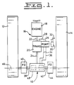
- a hydro-mechanical steering differential embodying the principles of the present invention is generally indicated at 10 in Fig. 1 for providing differential steering of the left and right hand tracks 12, 14, respectively, of a tractor drive train 16 for a track-type tractor or the like (not shown).
- the tractor drive train 16 includes an engine 18 and a transmission 20 connected to the engine by a drive shaft 22.
- the transmission is connected to the steering differential 10 by a transmission shaft 24 to provide a mechanical input to the steering differential.
- a hydraulic input to the steering differential is provided by a pump 26, preferably of a reversible, variable displacement type. Pump 26 may be operatively driven from the transmission by means of a suitable drive connection 28.
- the pump 26 is connected to a control valve 30, which is selectively actuated through a manual control 32.
- the pump 26 is connected by hydraulic lines 34 and 36 to the steering differential 10.
- the components of the steering differential 10 are preferably contained within and supported by a suitable case 48.
- a left output is provided by an axle shaft 38 extending from the left hand side of the case 48 and couples the steering differential 10 to the left track 12 through a left final drive 40.
- a right output is provided by an axle shaft 42 extending from the right hand side of the case 48 and couples the steering differential to the right track 14 through a right final drive 44.
- the axle shafts 38, 42 are disposed along a common transverse axle axis 46.
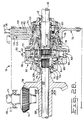
- the steering differential 10 includes a gearless hydro-mechanical differential unit 50, which is generally shown in Fig. 2B, and a geared mechanical differential unit 52, which is generally shown in Fig.2A.
- a gearless hydro-mechanical differential unit 50 which is generally shown in Fig. 2B
- a geared mechanical differential unit 52 which is generally shown in Fig.2A.
- the mechanical input from the transmission shaft 24 is connected to a bevel pinion 54 of the steering differential 10.
- Bevel pinion 54 meshes with a bevel gear 56.
- Bevel gear 56 is carried on a hollow shaft 58 disposed along the axle axis 46.
- the hollow shaft 58 provides the mechanical input to both the hydro-mechanical differential unit 50 and the mechanical differential unit 52.
- the gearless hydro-mechanical differential unit 50 includes a rotatable hydraulic motor 60.
- Such motor 60 is preferably of a low speed, high torque radial piston type as shown. It should be understood, however, that the present invention is not intended to be limited to a particular motor type, as those skilled in the art will readily be able to adapt other types of motors, such an axial piston type motor, as a rotatable motor for a gearless differential based upon and without departing from the teachings hereof. It should also be understood that the motor 60 itself may be of any well-known construction. Also, the general principles of operation of such motors are well understood by those skilled in the art. The uniqueness of the present invention is to have the entire motor 60 rotatable, as will hereinafter more fully described, which advantageously eliminates the requirement for separate gearing to perform the differential function.
- the motor 60 comprises a drive unit 62 and a driven unit 64.
- the drive unit 62 includes a cam plate 66.
- the cam plate 66 is mounted between a carrier 68 on the left and an annular support housing 70 on the right, as shown in Fig. 2B.
- the carrier 68 is coupled to the hollow shaft 58 by means of a spline connection 74 provided on a hub portion 72 of the carrier 68 and on an adjacent end 75 of the hollow shaft 58.
- the support housing 70 is rotatably supported to a stationary housing 76 by means of a suitable bearing 78. As should be readily apparent, this arrangement permits the entire motor 60 to rotate about the axle axis 46.
- the stationary housing 76 may be integral with the case 48 or bolted to the case as shown.
- the driven unit 64 comprises a cylinder block 80, pistons 82 and cylindrical rollers 84.
- the cylinder block 80 has a plurality of radially disposed cylinders therein, one depicted by reference number 86 and another depicted by reference number 88.
- One of the pistons 82 is reciprocatably disposed in each cylinder 86,88.
- the cam plate 66 is disposed about the cylinder block 80 and is provided with a suitable inner cam surface 90.
- Each piston 82 is provided with one of the cylindrical rollers 84 for rolling contact with the cam surface 90 of the cam plate 66.
- the cylinder block 80 is also provided with a plurality of fluid ports, one of such ports being shown at 92 for cylinder 86 and another being shown at 94 for cylinder 88 in Fig. 2B.
- the cylinder block 80 has a central opening 96 for receiving the axle shaft 42 therethrough and is coupled to the shaft by a spline connection at 98.
- the shaft 42 is preferably provided with an enlarged hollow end 100 for receiving the adjacent end of an intermediate shaft 102.
- the intermediate shaft 102 and axle shaft 42 are coupled together by a spline connection at 104.
- axle shaft 42 and intermediate shaft 102 could be constructed as a single component, but are preferably made as separate components as shown here for manufacturability and assembly purposes. Together, they form the right output as such term is used herein.
- the carrier 68 is rotatably supported by a suitable bearing 106 mounted about the end 100 of the axle shaft 42.
- pressurized hydraulic fluid from the pump 26 must be conducted to the motor 60 as it rotates.
- means 108 are provided for conducting pressurized hydraulic fluid from the pump 26 to the hydraulic motor 60 to effect the driving of the driven unit 64 of the hydraulic motor 60 by the drive unit 62.
- Such means 108 for conducting fluid includes first and second inlet/outlet ports 110 and 112 provided in the stationary housing 76 to which hydraulic lines 34 and 36, respectively are connected.
- Means 108 also preferably includes a pressure manifold 114 and an annular port plate 116 that are connected in a fixed relation to the stationary housing 76, an annular pressure force manifold 118 and a distributor valve 120 that are connected in a fixed relation to the support housing 70, and first and second passage means 122, 124.
- the first and second passage means 122, 124 are each separately disposed through the housing 76, pressure manifold 114, port plate 116, pressure force manifold 118 and distributor valve 120 to separately conduct fluid from the first and second inlet/outlet ports 110,112, respectively, to ports 92,94 of the hydraulic motor 60.
- a third or drain port 126 communicates through a third passage 128 with the interior of the housing 76 for draining off any fluid leakage from within the housing.
- the geared differential unit 52 is preferably a bevel gear differential 130, which includes a right hand bevel gear element 132, a left hand bevel gear element 134, and a gear carrier element 136.
- the carrier element 136 rotatably carries a set of spider gears 138. Each bevel gear element 132, 134 meshes with the set of spider gears 138.
- the right hand bevel gear element 132 is coupled to the intermediate axle shaft 102 by a spline connection 140 and, thus, to the right axle shaft 42 through spline connection 104.
- the left hand bevel gear element 134 is coupled to the left axle shaft 38 by a spline connection 142.
- the carrier element 136 is coupled to the bevel input gear 56 through the hollow shaft 58 by a spline connection 144.
- the carrier element 136 may be rotatably supported by a bearing 146 carried within a support member 148 that, in turn, is mounted to the case 48.
- a bearing 150 and support member 152 may be used to rotatably support the hollow shaft 58.
- the hydro-mechanic steering differential 10 constructed in accordance with the teachings of the present invention advantageously provides a steering differential with fewer components and gearing through the unique incorporation of a rotatable motor in the hydro-mechanical portion of the steering differential.
- the operation of the steering differential may be more readily understood by reference to the schematic representation of such steering differential depicted in Fig. 3.
- the mechanical input is transmitted from the transmission 20 through the transmission shaft 24 to the bevel pinion 54.
- the bevel pinion 54 drives the bevel gear 56.
- the bevel gear 56 is coupled to rotate both the carrier element 136 of the mechanical differential unit 52 and the drive unit 62 of the rotatable motor 60 at the same speed and in the same direction.
- a pivot turn is possible at zero velocity of the tractor. Under these conditions, there will be no mechanical output from the transmission 20 and the gear carrier 136, the bevel gear 56 and the drive unit 62 of the motor 60 will remain stationary.
- a hydraulic input to the motor 60 will cause the driven unit 64 to rotate in one direction when fluid pressure from the pump 26 is directed to the first inlet/outlet port 110 (see Fig. 2A) and in the opposite direction when such fluid pressure is directed to the second inlet/outlet port 112.
- the driven unit 64 rotates in the first direction, it drives the right output axle 42 and the right bevel gear 132 of the mechanical differential unit 52 in the same direction.
- the spider gears 138 which are driven by the right bevel gear 132, will drive the left bevel gear 134 and the left output axle 38 at the same speed, but in the opposite direction.
- the tracks 12, 14 will be traveling in opposite directions as well, effecting a pivot turn of the tractor.
- the steering differential 10 With this understanding of the operation of the steering differential 10, it should be readily apparent that turning will be similarly accomplished when the tractor is moving in forward or reverse directions as well. For instance, if a right turn is desired while the tractor is traveling in a forward direction, the steering differential 10 must cause the left track 12 to turn faster than the right track 14. To accomplish this, the motor 60 is operated to cause the driven unit 64 to turn in the opposite direction that the drive unit 62 is being rotated in by the bevel gear 56. This causes the right output axle 42 to turn at a slower speed than the gear carrier 136 of the mechanical differential unit 52. This in turn, will cause left output shaft 38 to turn at a speed greater than the carrier 136 through the differential action of the bevel gears 132 and 134 and the spider gears 138.
- the motor 60 must be operated to drive the driven unit 64 in the same direction that the drive unit 62 is being rotated in by the bevel gear 56, thereby causing the driven unit 64 to turn at a speed greater than the drive unit 62.
- the right output shaft 42 will turn at a speed greater than the left output shaft 38, thus effecting a left hand turn.
- the hydro-mechanical steering differential of the present invention is effective in providing smooth, equal and uninterrupted power and torque flow to both tracks at all times, including turns. Furthermore, such turning is infinitely variable throughout the speed of the motor 60.
Landscapes
- Engineering & Computer Science (AREA)
- Chemical & Material Sciences (AREA)
- Combustion & Propulsion (AREA)
- Transportation (AREA)
- Mechanical Engineering (AREA)
- Retarders (AREA)
- Motor Power Transmission Devices (AREA)
- Non-Deflectable Wheels, Steering Of Trailers, Or Other Steering (AREA)
Claims (3)
- Hydromechanisches Lenkdifferential (10) zum Vorsehen einer Differentiallenkung der linken und rechten Gleisketten (12,14) eines Traktors bzw. einer Zugmaschine, und wobei das Lenkdifferential (10) durch eine mechanische Eingabe bzw. ein Eingang und eine hydraulische Eingabe bzw. ein Eingang angetrieben wird und linke und rechte Ausgänge an den linken und rechten Gleisketten (12,14) aufweist, wobei das Differential folgendes aufweist: eine mit Zähnen versehene Differentialeinheit (52) mit einem rechten Ausgangszahnradelement (132), einem linken Ausgangszahnradelement (134) und einem Zahnradträgerelement (136), wobei das Zahnradträgerelement (136) mit dem mechanischen Eingang gekoppelt ist und einen Zahnradsatz aufweist, der mit den rechten und linken Ausgangszahnradelementen (132,134) ineinandergreift, wobei das linke Ausgangszahnradelement (134) mit dem linken Ausgang gekoppelt ist und das rechte Ausgangszahnradelement (132) mit dem rechten Ausgang gekoppelt ist; und eine zahnradlose, hydromechanische Differentialeinheit (50) mit einem drehbaren Motor (60), der durch die Hydraulikeinheit angetrieben wird, wobei die hydromechanische Differentialeinheit (50) eine Antriebseinheit (62) aufweist, die mit dem mechanischen Eingang gekoppelt ist, und eine angetriebene Einheit (64), die mit dem rechten Ausgang gekoppelt ist; dadurch gekennzeichnet, daß die hydromechanische Differentialeinheit (50) ein stationäres Gehäuse (76), einen Träger (68) zum Koppeln der Antriebseinheit des Motors (60) mit dem mechanischen Eingang und ein Traggehäuse (70) zum drehbaren Anbringen der Antriebseinheit (62) an dem stationären Gehäuse (76) aufweist; und durch Mittel (108) zum Leiten von Hydraulikströmungsmittel von dem Hydraulikeingang an den Motor, die eine Drucksammelleitung (114) und eine ringförmige Anschlußplatte (116), die in einer festen Beziehung zu dem stationären Gehäuse (76) verbunden ist, und eine ringförmige Druckkraftsammelleitung (118) und ein Verteilerventil (120) aufweisen, die in einer festen Beziehung zu dem Traggehäuse (70) verbunden sind.
- Differential (10) nach Anspruch 1, wobei der Motor (60) der hydromechanischen Differentialeinheit (50) des Radialkolbentyps mit niedriger Drehzahl und hohem Drehmoment ist, mit einer Nockenplatte (66), die als die Antriebseinheit (62) dient und einer Kolbeneinheit, die als die angetriebene Einheit (64) dient.
- Differential (10) nach Anspruch 1 oder 2, wobei der Motor (60) eine Vielzahl von Strömungsmittelanschlüssen (92,94) aufweist, und die Mittel (108) zum Leiten von Hydraulikströmungsmittel erste und zweite Einlaß-/Auslaßanschlüsse (110,112) und erste und zweite Durchlaßmittel (122,124) aufweisen zum Leiten von Strömungsmittel von den ersten und zweiten Einlaß-/Auslaßanschlüssen (110,112) zu Ausgewählten der Anschlüsse (92,94) des Motors (60) während des Betriebs des Motors (60).
Applications Claiming Priority (3)
| Application Number | Priority Date | Filing Date | Title |
|---|---|---|---|
| US179212 | 1994-01-10 | ||
| US08/179,212 US5415596A (en) | 1994-01-10 | 1994-01-10 | Hydro-mechanical steering differential apparatus |
| PCT/US1994/014375 WO1995018736A1 (en) | 1994-01-10 | 1994-12-12 | Hydro-mechanical steering differential apparatus |
Publications (2)
| Publication Number | Publication Date |
|---|---|
| EP0687232A1 EP0687232A1 (de) | 1995-12-20 |
| EP0687232B1 true EP0687232B1 (de) | 1999-01-27 |
Family
ID=22655692
Family Applications (1)
| Application Number | Title | Priority Date | Filing Date |
|---|---|---|---|
| EP95904902A Expired - Lifetime EP0687232B1 (de) | 1994-01-10 | 1994-12-12 | Hydro-mechanisches lenkungsdifferentialgetriebe |
Country Status (5)
| Country | Link |
|---|---|
| US (1) | US5415596A (de) |
| EP (1) | EP0687232B1 (de) |
| JP (1) | JPH08507992A (de) |
| CA (1) | CA2154449A1 (de) |
| WO (1) | WO1995018736A1 (de) |
Families Citing this family (15)
| Publication number | Priority date | Publication date | Assignee | Title |
|---|---|---|---|---|
| US5529136A (en) * | 1995-04-13 | 1996-06-25 | Caterpillar Inc. | Articulated machine with powered differential steering |
| US6520880B1 (en) | 1996-08-22 | 2003-02-18 | Unisia Jecs Corporation | Traction distributing devices for motor vehicles |
| US5857532A (en) * | 1996-11-27 | 1999-01-12 | Caterpillar Inc. | Differential steer system for a machine |
| SE511192C2 (sv) * | 1997-03-27 | 1999-08-23 | Unic Ab | Anordning vid differentialväxel för fordon |
| US6148939A (en) * | 1998-12-22 | 2000-11-21 | Caterpillar Inc. | Variable gain steering control system for a work machine |
| US6454032B1 (en) * | 1999-03-26 | 2002-09-24 | Deere & Company | Lawn tractor vehicle |
| US6478706B1 (en) * | 1999-12-17 | 2002-11-12 | Caterpillar Inc | Planetary steering differential |
| JP4058213B2 (ja) * | 2000-01-20 | 2008-03-05 | 株式会社日立製作所 | 車両の左右駆動力配分装置 |
| DE10102366B4 (de) * | 2000-01-20 | 2007-01-25 | Hitachi, Ltd. | Traktionsverteilungsvorrichtung für ein Kraftfahrzeug |
| DE10164940B4 (de) * | 2000-01-20 | 2008-01-24 | Hitachi, Ltd. | Traktionsverteilungsvorrichtung für ein Kraftfahrzeug |
| US6572344B1 (en) | 2001-11-26 | 2003-06-03 | Caterpillar Inc | Compact pump or motor with internal swash plate |
| US7441623B2 (en) * | 2005-02-28 | 2008-10-28 | Caterpillar Inc. | Multi-motor drive system for a work machine |
| US7942220B2 (en) * | 2006-12-22 | 2011-05-17 | Caterpillar Inc. | Differential steering control for a continuously variable transmission machine |
| FR3020324B1 (fr) * | 2014-04-25 | 2016-04-22 | Poclain Hydraulics Ind | Ensemble d'entrainement pour un arbre moteur d'un vehicule automobile |
| JP6569372B2 (ja) * | 2015-08-07 | 2019-09-04 | 株式会社豊田中央研究所 | 動力配分装置 |
Family Cites Families (10)
| Publication number | Priority date | Publication date | Assignee | Title |
|---|---|---|---|---|
| US2004929A (en) * | 1931-11-25 | 1935-06-18 | Manly Corp | Control means for varying the relative speeds of members driven through a common differential mechanism |
| US2336911A (en) * | 1941-09-05 | 1943-12-14 | Vickers Inc | Power transmission and steering control for traction devices |
| US3368425A (en) * | 1965-05-27 | 1968-02-13 | Gen Electric | Steering and driving power system |
| DE1245760B (de) * | 1965-06-30 | 1967-07-27 | Zahnradfabrik Friedrichshafen | UEberlagerungslenkgetriebe fuer Gleiskettenfahrzeuge |
| DE3009793A1 (de) * | 1979-03-29 | 1980-10-09 | Cyphelly Ivan J | Ueberlagerungs-lenkantrieb fuer ein fahrzeug |
| US4423644A (en) * | 1979-08-20 | 1984-01-03 | Caterpillar Tractor Co. | Multi-speed planetary differential |
| US4434680A (en) * | 1980-09-02 | 1984-03-06 | Caterpillar Tractor Co. | Planetary steering differential |
| US4557157A (en) * | 1983-03-14 | 1985-12-10 | Caterpillar Tractor Co. | Vehicle steering differential |
| DE3531632A1 (de) * | 1985-09-05 | 1987-03-12 | Rexroth Mannesmann Gmbh | Radialkolbenmaschine |
| DE3835752A1 (de) * | 1988-10-20 | 1990-04-26 | Fiatgeotech S P A | Kettenfahrzeug mit einem epizyklischen lenkdifferential |
-
1994
- 1994-01-10 US US08/179,212 patent/US5415596A/en not_active Expired - Fee Related
- 1994-12-12 EP EP95904902A patent/EP0687232B1/de not_active Expired - Lifetime
- 1994-12-12 WO PCT/US1994/014375 patent/WO1995018736A1/en not_active Ceased
- 1994-12-12 JP JP7518491A patent/JPH08507992A/ja active Pending
- 1994-12-12 CA CA002154449A patent/CA2154449A1/en not_active Abandoned
Also Published As
| Publication number | Publication date |
|---|---|
| EP0687232A1 (de) | 1995-12-20 |
| WO1995018736A1 (en) | 1995-07-13 |
| JPH08507992A (ja) | 1996-08-27 |
| US5415596A (en) | 1995-05-16 |
| CA2154449A1 (en) | 1995-07-13 |
Similar Documents
| Publication | Publication Date | Title |
|---|---|---|
| EP0687232B1 (de) | Hydro-mechanisches lenkungsdifferentialgetriebe | |
| US5390751A (en) | Planetary steering system for a skid-steered vehicle | |
| EP0203688B1 (de) | Hydrostatische Treibachsvorrichtung | |
| US4471669A (en) | Track drive system with dual mode steering | |
| US4718508A (en) | Driving and steering system | |
| US4431073A (en) | Two speed final drive gear box | |
| US4882947A (en) | Track-laying device | |
| US6641497B2 (en) | Epicyclic transmission for zero turning radius vehicles | |
| CA2117137A1 (en) | Dual hydraulic motor drive system | |
| EP0636814B1 (de) | Mechanisches Getriebe für Antriebsräder, insbesondere für fahrbare Arbeitmaschine | |
| US6478706B1 (en) | Planetary steering differential | |
| EP2125492B1 (de) | Antriebsanordnung für ein schlupfgelenktes fahrzeug | |
| EP0688409B1 (de) | Zahnradloses hydromechanisches getriebe | |
| GB1595124A (en) | Dual path dual range transmission | |
| US4763543A (en) | Transmission for a working vehicle | |
| US5545098A (en) | Compact steering apparatus | |
| EP0216540A1 (de) | Leistungsgetriebe für Drehbewegungsübertragung | |
| RU82183U1 (ru) | Механизм бесступенчатого поворота транспортной машины (варианты) | |
| CA1147578A (en) | Planetary steering differential | |
| US20030106764A1 (en) | Hydro-mechanical combiner | |
| JPH11189169A (ja) | 変速操向装置 | |
| JPH0110259Y2 (de) | ||
| AU538375B2 (en) | Planetary steering differential | |
| KR0138788B1 (ko) | 이동농기의 주행전동장치 | |
| JPH08175204A (ja) | 静流体圧式変速装置付クローラ走行装置 |
Legal Events
| Date | Code | Title | Description |
|---|---|---|---|
| PUAI | Public reference made under article 153(3) epc to a published international application that has entered the european phase |
Free format text: ORIGINAL CODE: 0009012 |
|
| 17P | Request for examination filed |
Effective date: 19950922 |
|
| AK | Designated contracting states |
Kind code of ref document: A1 Designated state(s): FR GB IT |
|
| 17Q | First examination report despatched |
Effective date: 19970424 |
|
| GRAG | Despatch of communication of intention to grant |
Free format text: ORIGINAL CODE: EPIDOS AGRA |
|
| GRAG | Despatch of communication of intention to grant |
Free format text: ORIGINAL CODE: EPIDOS AGRA |
|
| GRAH | Despatch of communication of intention to grant a patent |
Free format text: ORIGINAL CODE: EPIDOS IGRA |
|
| GRAH | Despatch of communication of intention to grant a patent |
Free format text: ORIGINAL CODE: EPIDOS IGRA |
|
| GRAA | (expected) grant |
Free format text: ORIGINAL CODE: 0009210 |
|
| AK | Designated contracting states |
Kind code of ref document: B1 Designated state(s): FR GB IT |
|
| ITF | It: translation for a ep patent filed | ||
| ET | Fr: translation filed | ||
| PGFP | Annual fee paid to national office [announced via postgrant information from national office to epo] |
Ref country code: FR Payment date: 19990908 Year of fee payment: 6 |
|
| PGFP | Annual fee paid to national office [announced via postgrant information from national office to epo] |
Ref country code: GB Payment date: 19990912 Year of fee payment: 6 |
|
| PLBE | No opposition filed within time limit |
Free format text: ORIGINAL CODE: 0009261 |
|
| STAA | Information on the status of an ep patent application or granted ep patent |
Free format text: STATUS: NO OPPOSITION FILED WITHIN TIME LIMIT |
|
| 26N | No opposition filed | ||
| PG25 | Lapsed in a contracting state [announced via postgrant information from national office to epo] |
Ref country code: GB Free format text: LAPSE BECAUSE OF NON-PAYMENT OF DUE FEES Effective date: 20001212 |
|
| GBPC | Gb: european patent ceased through non-payment of renewal fee |
Effective date: 20001212 |
|
| PG25 | Lapsed in a contracting state [announced via postgrant information from national office to epo] |
Ref country code: FR Free format text: LAPSE BECAUSE OF NON-PAYMENT OF DUE FEES Effective date: 20010831 |
|
| REG | Reference to a national code |
Ref country code: FR Ref legal event code: ST |
|
| PG25 | Lapsed in a contracting state [announced via postgrant information from national office to epo] |
Ref country code: IT Free format text: LAPSE BECAUSE OF NON-PAYMENT OF DUE FEES Effective date: 20051212 |