EP0688409B1 - Zahnradloses hydromechanisches getriebe - Google Patents
Zahnradloses hydromechanisches getriebe Download PDFInfo
- Publication number
- EP0688409B1 EP0688409B1 EP95906628A EP95906628A EP0688409B1 EP 0688409 B1 EP0688409 B1 EP 0688409B1 EP 95906628 A EP95906628 A EP 95906628A EP 95906628 A EP95906628 A EP 95906628A EP 0688409 B1 EP0688409 B1 EP 0688409B1
- Authority
- EP
- European Patent Office
- Prior art keywords
- manifold
- fluid
- unit
- motor
- transmission
- Prior art date
- Legal status (The legal status is an assumption and is not a legal conclusion. Google has not performed a legal analysis and makes no representation as to the accuracy of the status listed.)
- Expired - Lifetime
Links
Images


Classifications
-
- F—MECHANICAL ENGINEERING; LIGHTING; HEATING; WEAPONS; BLASTING
- F16—ENGINEERING ELEMENTS AND UNITS; GENERAL MEASURES FOR PRODUCING AND MAINTAINING EFFECTIVE FUNCTIONING OF MACHINES OR INSTALLATIONS; THERMAL INSULATION IN GENERAL
- F16H—GEARING
- F16H47/00—Combinations of mechanical gearing with fluid clutches or fluid gearing
- F16H47/02—Combinations of mechanical gearing with fluid clutches or fluid gearing the fluid gearing being of the volumetric type
Definitions
- the present invention generally relates to hydro-mechanical transmission apparatus and more particularly to a hydro-mechanical transmission having fluid motor that is entirely rotatable to eliminate the need for separate gearing.
- hydro-mechanical variable ratio transmission is disclosed in U.S. -A-3,905,251.
- This transmission utilizes either a planetary gear mechanism or a bevel gear type differential mechanism to combine the mechanical and hydraulic inputs.
- an in-line motor is disclosed in one embodiment of this patent, such motor is not revolvable, thus necessitating the use of separate gearing, adding to the complexity and cost and preventing compactness of the unit.
- a dual hydraulic unit which can be used as a double pump or double motor, or as a hydrostatic transmission.
- the dual pump/motor arrangement makes the unit large and complex. Further, such dual device does not provide a gearless transmission with separate mechanical and hydraulic inputs and a combined output. Also, the dual axis piston pump/motor design is not fully compatible to a radial piston motor design.
- US-A-5018351 discloses a hydromechanical drive in which input and output shafts are coupled by a hydraulically driven clutch.
- the pressure and/or flow rate of the fluid in the clutch is adjustable by a valve or wobble plate.
- a gearless hydro-mechanical transmission for providing a variable speed and torque output from an external mechanical power source and an external infinitely variable hydraulic power source, comprising: a stationary case; an output shaft mounted within the case for rotation about a central axis; a mechanical input mounted in coaxial alignment with the output shaft for rotation about the central axis, the input being connected to and rotatably driven by the mechanical power source; a rotatable hydraulic motor having first and second fluid chambers, and a drive unit for rotatably driving a driven unit, the driven unit being coupled to drive the output shaft; and means for conducting pressurised hydraulic fluid from the hydraulic power source to the hydraulic motor for driving the driven unit of the hydraulic motor by the drive unit the means including a pressure manifold, an annular port plate, an annular pressure force manifold, a distributor valve, and first and second passage means.
- a gearless hydro-mechanical transmission for providing a variable speed and torque output from an external mechanical power source and an external infinitely variable hydraulic power source, comprising: a stationary case having a first inlet/outlet port and a second inlet/outlet port to which hydraulic fluid is communicated from the power source; an output shaft mounted within the case for rotation about a central axis; a mechanical input mounted in coaxial alignment with the output shaft for rotation about the central axis, the input being connected to and rotatably driven by the mechanical power source; a rotatable hydraulic motor having first and second fluid chambers, and a driven unit for rotatably driving a driven unit the driven unit being coupled to drive the output shaft; and means for conducting pressurised hydraulic fluid from the hydraulic power source to the hydraulic motor for driving the driven unit of the hydraulic motor by the drive unit, the means including a pressure manifold, an annular port plate, an annular pressure force manifold, a distributor valve, and first and second passage means, the pressure manifold being carried
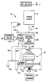
- a hydro-mechanical transmission embodying the principles of the present invention is generally indicated at 10 in Fig. 1 for use in a power unit 12.
- Such power unit 12 may be of any well known configuration, but for illustrative purposes is depicted in Fig. 1 as including a primary source of power, such as an internal combustion engine or other prime mover 14, a driven member 16, and a drive train 18 for coupling the prime mover 14 to the driven member 16.
- the power unit also includes a hydraulic source of power in the form of a variable displacement hydraulic pump 20, which can be of any well-known construction.
- the pump 20 may be controlled through a conventional valve 22 operated by a manual control lever 24, as well known in the art.
- the drive train 18 includes a drive shaft 26 to interconnect the engine 14 to the hydro-mechanical transmission 10.
- the drive train 18 may, but is not required to, include a conventional mechanical transmission or gear reduction unit 28 that is interposed in the drive train 18 between the engine and the hydro-mechanical transmission 10.
- the drive train 18 also preferably includes a set of gears for powering the pump 20, the first gear 30 being coupled to and driven by the drive shaft 26 and meshing with a second gear 32, which is coupled to the pump 20.
- a first hydraulic line 34 connects the pump 20 to a first port 35 of the hydro-mechanical transmission 10.
- a second hydraulic line 36 connects the pump 20 to a second port 37.
- a third hydraulic line 38 preferably connects the transmission 10 and pump 20 to tank 40.
- the hydro-mechanical transmission 10 includes a stationary case 42, an output shaft 44, a mechanical input 46 and a rotatable hydraulic motor 48.
- the output shaft 44 is rotatably mounted within the case by a suitable bearing 50 for rotation about a central axis 52 and has a splined end 54 protruding from the case 42 for use in coupling the shaft 44 to the driven member 16.
- the mechanical input 46 comprises an annular hub 56 having an internal spline 58 at its distal end for use in coupling the input to the drive shaft 26.
- the motor 48 is of a low speed, high torque radial piston type. It should be understood that the present invention is not intended to be limited to a particular motor type, as those skilled in the art will readily be able to adapt to the types of motors based upon and without departing from the teachings hereof.
- the motor 48 may also be of any well-known construction and its operation is well understood by those skilled in the art. For sake of clarity of understanding and comparison between this embodiment and the embodiment depicted in Fig. 5, the motor 48 is described as having a drive unit 60 and a driven unit 62.
- the driven unit 62 comprises a cylinder block 64, pistons 66 and cylindrical rollers 68.
- the drive unit 60 comprises a cam plate 70.
- the cylinder block 64 has a plurality of radially disposed cylinders therein, one depicted by reference number 72 and another depicted by reference number 74.
- One of the pistons 66 is reciprocatably disposed in each cylinder 72, 74.
- the cam plate 70 is disposed about the cylinder block 64 and is provided with a suitable inner cam surface 76.
- Each piston 66 is provided with one of the cylindrical rollers 68 for rolling contact with the cam surface 76 of the cam plate 70.
- the cylinder block 64 is also provided with a plurality of fluid ports that extend from a radial port face 78 to each of the of cylinders, one of such ports being shown at 80 for cylinder 72 and another being shown at 82 for cylinder 74 in Fig. 2.
- the hydro-mechanical transmission 10 also includes means 84 for rotatably supporting the hydraulic motor 48 to permit the rotation of the motor 48 relative to the stationary case 42 about the central axis 52.
- Rotatable support of the motor 48 is accomplished as follows.
- the cam plate 70 of the motor is mounted between flanges 86 and 88 and retained by bolts 90.
- Flange 86 is provided on a distributor housing 92, while flange 88 is provided on the hub 56 of the mechanical input 46.
- the hub 56 is rotatably mounted about an enlarged end 94 of the output shaft 44 by a suitable bearing 96.
- the distributor housing 92 is rotatably mounted to the stationary case by a second bearing 98.
- the hydro-mechanical transmission 10 further includes means 100 for conducting pressurized hydraulic fluid from the hydraulic power source 20 to the hydraulic motor 48 to effect the driving of the driven unit 62 of the hydraulic motor 48 by the drive unit 60.
- means 100 for conducting fluid includes a pressure manifold 102, an annular port plate 104, an annular pressure force manifold 106, a distributor valve 108, and first and second passage means 110, 112.
- the pressure manifold 102 is carried by the stationary case 42 by being disposed within a suitable bore 114 of the case and retained therein by bolts 116.
- the port plate 104 is carried by the pressure manifold 102 by mounting to an end face 118 of the manifold and retained thereto by dowel pins 120.
- the distributor valve 108 is carried by and rotatable with the mechanical input 46 and drive unit 60 of the hydraulic motor 48. This is accomplished by a stepped bore 122 in the distributor housing 92 and a mating stepped surface 124 on the periphery of the distributor valve 108.
- the mating stepped surface 124 of the valve is adapted to be slidably received within the stepped bore 122 of the housing 92 to permit relative axial movement therebetween so as to permit contact of a mating end face 126 of the valve with the port face 78 on the cylinder block 64 of the motor 48. Relative rotation between the distributor valve 108 and the housing 92 is prevented by a radially extending key 128 on the valve 108 that extends into a mating notch 130 provided in the housing 92.
- the pressure force manifold 106 is carried within the valve as follows.
- the distributor valve 108 is provided with a double stepped annular opening 132 therethrough.
- the pressure force manifold 106 is provided with a mating double stepped outer periphery 134 that is slidably received within the stepped opening 132 of the valve 108.
- the valve 108 and manifold 106 are of suitable construction to provide a pair of pressure chambers 136, 138 between the steps. Relative rotation between the pressure force manifold 106 and the distributor valve 108 is prevented by a radially extending key 140 at the end of the manifold which extends into a mating notch 142 in the distributor valve.
- the first and second passage means 110, 112 are each separately disposed through the case 42, pressure manifold 102, port plate 104, pressure force manifold 106 and distributor valve 108 to separately conduct fluid from the first and second inlet/outlet ports 35, 37, respectively, to ports 80, 82 of the hydraulic motor 48.
- first passage means 110 includes as follows: A radial passage 144 through the case 42 communicating with a first peripheral groove 146 about the pressure manifold 102, the first groove 146 communicates with a first plurality of passages 148 terminating at an inner set of openings 150 at the face 118 of the manifold 102 in contact with the port plate 104. Such inner set of openings communicate with a mating set of inner passages 152 through the port plate 104.
- the inner passages 152 of the port plate 104 communicate with a similar set of inner passages 154 through the pressure force manifold 106.
- Such inner passages 154 communicate with the inner pressure chamber 136 between the pressure force manifold 106 and the distributor valve 108.
- the inner pressure chamber 136 communicates with a first set of passages 156 through the distributor valve 108 which communicate with certain ones of the ports 80, 82 of the cylinder block 64, as will hereinafter be more fully described.
- the second passage means 112 includes as follows: A second radial passage 158 through the case 42 communicating with a second peripheral groove 160 about the pressure manifold 102, the second groove 160 communicates with a second plurality of passages 162 terminating at an outer set of openings 164 at the face of the manifold in contact with the port plate 104. Such outer set of openings 164 communicate with a mating set of outer passages 166 through the port plate 104.
- the outer passages 166 of the port plate 104 communicate with a similar set of outer passages 168 through the pressure manifold. Such outer passages 168 communicate with the outer pressure chamber 138 between the pressure force manifold 106 and the distributor valve 108.
- the outer pressure chamber 138 communicates with a second set of passages 170 through the distributor valve 108 which communicate with certain other ones of ports of the cylinder block.
- the third or drain port 39 communicates through a third passage 172 (Fig. 2) with the interior of the case 42 for draining off any fluid leakage from within the case.
- a first set of suitable seals 174 are provided on opposite sides of the grooves 146, 160 and passages 144, 158 to prevent fluid leakage between the case 42 and the manifold 102.
- a second set of suitable seals 176 are provided between the mating stepped periphery between the distributor valve 108 and the pressure force manifold 106 to similarly prevent fluid leakage therebetween.
- the entire assemblage is preferably sealed by suitable seals, such as a seal 178 between the case 42 and output shaft 44, a seal 180 between the case 42 and the distributor housing, and a seal 182 between the hub 56 and the enlarged end of the output shaft 44.
- suitable seals such as a seal 178 between the case 42 and output shaft 44, a seal 180 between the case 42 and the distributor housing, and a seal 182 between the hub 56 and the enlarged end of the output shaft 44.
- the cylinder block 64 is supported on and axially abuts a stepped shoulder 184 on the output shaft 44.
- the block 64 and shaft 44 are rotatably coupled together by a spline connection at 186.
- a nut 188 mounted on a threaded portion 190 of the shaft 44 abuts a bearing carrier 192.
- a thrust bearing 194 is interposed between the carrier 192 and the manifold 102.
- a plurality of axial pre-load springs one of which is shown at 196, may be employed to assist in maintaining the axial sealing faces engaged.
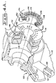
- FIG. 5 An alternate embodiment of the present invention is shown in Fig. 5. It should be noted that many of the components depicted in Fig. 5, particularly on the left hand side from the case 42 to the pressure force manifold 106, are identical with those depicted in the previous embodiment.
- the distributor valve 108 is basically the same, but may have somewhat different porting to accommodate the design of the axial piston pump, rather than that of the radial piston pump. Such components are provided with the same numbers and, for sake of brevity, will not be further described, except in connection with the new components hereinafter described.
- the embodiment of the hydro-mechanical transmission depicted in Fig. 5 generally functions in the same manner as the previous embodiment, but instead of the use of a radial piston motor 48 described earlier, the Fig. 5 embodiment employs an axial piston motor 248.
- the axial piston motor 248 similarly includes a drive unit 260 and a driven unit 262.
- the drive unit 260 is comprised of an input hub 256 and a cylindrical casing 250.
- the casing 250 is mounted by bolts 90 to the flange 86 of the distributor housing 92.
- the other end of the casing 250 is similarly attached to a flange 254 of the hub 256 by bolts 252.
- the hub 256 is provided with a suitable splined bore 258 for coupling the hub 256 to the drive shaft 26 (not shown).
- the hub has an angled interior side portion 264.
- An angled support shaft 266 extends from the interior side portion 264 of the hub.
- An annular swash plate 268 is disposed about and rotatably mounted to the support shaft 266 by roller bearing 270 so as to rotate at an angle relative to the central axis 52.
- the swash plate 268 is also supported by a thrush bearing 272 between it and the angled side portion 264.
- the driven unit 262 is comprised of an annular cylinder block 274 having a plurality of lined, axially oriented cylinders 276 and a like plurality of pistons 278 reciprocatably mounted within such cylinders.
- the pistons 278 have rounded ends 280 for rocking contact with the swash plate.
- the cylinder block 274 is also provided with a like plurality of fluid ports that extend from a radial port face 282 to each of the of cylinders, one of such ports being shown at 284 for cylinder 276 and another being shown at 285 for cylinder 277.
- the cylinder block 274 is rotatably coupled to the output shaft 244 by a spline connection 286.
- the hydro-mechanical transmission 10 constructed in accordance with the teachings of the present invention advantageously provides a variable speed and torque output from an external mechanical power source 12 and an external hydraulic power 20 source in a simple, compact package and without the use of gearing.
- the function of the distributor valve 108 is to selectively time the communication of fluid from either the first port 35 or the second port 37 to the cylinder ports 80, 82 & 284, 285 in response to the relative rotational position of the cylinder block 64, 274 with the cam plate 70 or swash plate 268, as known in the art.
- port plate 104 has a radial face 200 having an annular inner groove 202 and an annular outer groove 204.
- the grooves 202, 204 are separated by a sealing land 206.
- a separate outer sealing land 208 surrounds the outer groove 204 and separate inner sealing land 210 lies internally of the inner groove 202.
- Such lands 206, 208, 210 are disposed in sealing contact with mating lands (not shown) on the pressure force manifold 106.
- the respective lands are maintained in metal-to-metal face sealing contact with each other during operation by fluid pressure in the pressure chambers 136, 138 that generate an axial force when pressurized fluid is present in such chambers for urging the sealing face of the pressure force manifold 106 into sealing contact with the mating face 200 of the port plate 104, as well as the contacting port faces 78, 282, 126 of the cylinder block 64, 274 and the distributor valve 108.
- the driven unit 62, 262 is driven in one direction relative to the drive unit 60, 62 when pressurized fluid is directed to the first port 35, the driven unit 62, 262 is driven in an opposite direction when pressurized fluid is directed to the second port 37, and the drive and driven units are locked relative to each other when pressurized fluid is blocked from escaping from both of the first and second ports 35, 37.
- Fluid is selectively directed to the first 35 and second 37 ports from the pump 20 by the control valve 22 through manual manipulation of the hand lever 24, as well known in the art.
- the drive unit 60, 260 of the motor 48, 248 is coupled to rotate with the mechanical input 46, 246 and the driven unit 62, 262 is coupled to rotate with the output shaft 44, 244, the following drive combinations will result.
- the output shaft 44, 244 will turn at the same speed as the input 46, 246 when pressurized fluid is blocked to the first and second ports 35, 37.
- the mechanical input 46, 246 rotates the drive unit in a clockwise direction, as view in Fig.3
- the driven unit 62, 262 is also driven in a clockwise direction when fluid pressure is directed to the first port 35
- the output shaft 44, 244 will turn at a speed equal to the sum of the speeds of the input 46, 246 and motor 48, 248.
- variable speed and torque output from the hydro-mechanical transmission 10 to the driven member 16 is possible within a range of from a high equalling the combined speeds of the motor 48, 248 and input 46, 246 to a low equalling the difference between the speeds of the input 46, 246 and motor 48, 248.
- speed differential between the motor 48, 248 and input 46, 246, the low speed could result in the direction of rotation of the output shaft 44, 244 being opposite to that of the input 46, 246.
Landscapes
- Engineering & Computer Science (AREA)
- General Engineering & Computer Science (AREA)
- Mechanical Engineering (AREA)
- Hydraulic Motors (AREA)
Claims (8)
- Zahnradloses hydromechanisches Getriebe (10) zum Vorsehen einer variablen Drehzahl- und Drehmomentausgangsgröße von einer externen mechanischen Leistungsquelle (12) und einer externen, unbegrenzt variablen hydraulischen Leistungsquelle (20), wobei folgendes vorgesehen ist:ein stationäres Gehäuse (42) mit einem ersten Einlaß-/Auslaßanschluß (35) und einem zweiten Einlaß-/Auslaßanschluß (37) mit dem hydraulische Strömungsmittel von der Leistungsquelle (20) in Verbindung steht;eine Abtriebswelle (44/244) angeordnet innerhalb des Gehäuses (42) zur Drehung um eine Mittelachse (52);ein mechanisches Eingangselement (46/246) angeordnet in koaxialer Ausrichtung mit der Abtriebswelle (44/244) zur Drehung um die Zentrale oder Mittelachse (52), wobei das Eingangselement (46/246) mit der mechanischen Leistungsquelle verbunden ist und drehbar durch diese angetrieben wird;ein drehbarer Hydraulikmotor (48/248) mit ersten und zweiten Strömungsmittelkammern und einer Antriebseinheit (60, 260) zum Drehantrieb einer angetriebenen Einheit (62/262), wobei die angetriebene Einheit (62/262) zum Antrieb der Abtriebswelle (44, 244) angekurbelt ist; undMittel (100) zum Leiten von unter Druck stehendem hydraulischen Strömungsmittel von der hydraulischen Leistungsquelle (20) zum hydraulischen Motor (48/248) zum Antreiben der angetriebenen Einheit (62/262) des hydraulischen Motors (48/248) durch die Antriebseinheit (60/260), wobei die strömungsmittelleitenden Mittel (100) eine Drucksammelleitung (102), eine Ringanschlußplatte (104), eine ringförmige Druckkraftsammelleitung (106), ein Verteilerventil (108) und erste und zweite Durchlaßmittel (110, 112) aufweisen, wobei die Drucksammelleitung (102) durch das Gehäuse (42) getragen ist, während die Anschlußplatte (104) durch die Druckkraftsammelleitung (106) getragen ist und das Verteilerventil (108) durch die Antriebseinheit (60/62) des Hydraulikmotors (48/248) getragen wird und drehbar ist, wobei ferner die Druckkraftsammelleitung (106) innerhalb des Verteilerventils (108) getragen ist, wobei die ersten und zweiten Durchlaßmittel (110, 112) jeweils gesondert angeordnet sind, durch das Gehäuse (42), die Drucksammelleitung (102), die Anschlußplatte (104), die Druckkraftsammelleitung (106) und das Verteilerventil (108), um gesondert Strömungsmittel von den ersten bzw. zweiten Einlaß-/Auslaßanschlüssen (35, 37) zu den ersten und zweiten Kammern des Hydraulikmotors (28/248) zu leiten, wodurch das Leiten von Strömungsmittel von dem ersten Einlaß-/Auslaßanschluß (35) zu den ersten Kammern bewirkt, daß die angetriebene Einheit (62/262) in einer Richtung sich dreht, und wobei das Leiten von Strömungsmittel von dem zweiten Einlaß-/Auslaßanschluß (37) zu den zweiten Strömungsmittelkammern bewirkt, daß die angetriebene Einheit sich in der entgegengesetzten Richtung dreht.
- Getriebe (10) nach Anspruch 1, wobei die Anschlußplatte (104) eine radial angeordnete Dichtstirnfläche darauf aufweist, und wobei die Drucksammelleitung (102) eine zusammenpassende, radial angeordnete Dichtstirnoberfläche darauf angeordnet aufweist, und zwar in einem Stirnflächen-Abdichtdrehkontakt mit der Abdichtstirnfläche der Anschlußplatte (104).
- Getriebe (10) nach Anspruch 2, wobei das Verteilerventil (108) eine doppelt abgestufte Ringöffnung (132) dahin durchlaufend aufweist, und wobei die Druckkraftsammelleitung (106) einen zusammenpassenden doppelt abgestuften Außenumfang (134) aufweist, der gleitend innerhalb der abgestuften Öffnung (132) des Ventils (108) aufgenommen ist und ein Paar von Druckkammern (136, 138) dazwischen vorsieht, wobei jede Kammer (136, 138) in Verbindung steht mit einer entsprechenden der ersten bzw. der zweiten Durchlaßmittel (110, 112) zur Schaffung einer Axialkraft, um die Abdichtfläche der Druckkraftsammelleitung (106) in Abdichtkontakt mit der Stirnfläche der Anschlußplatte (104) zu drücken.
- Getriebe (10) nach einem der vorhergehenden Ansprüche, wobei die angetriebene Einheit (62/262) eine dahin durchverlaufende Mittelöffnung aufweist, die interne Keilbahnmittel (58) aufweist, und zwar in Eingriff stehend mit damit zusammenpassenden externen Keilbahnmitteln an der Abtriebswelle (44/244).
- Getriebe (10) nach einem der vorhergehenden Ansprüche, wobei der Hydraulikmotor (48/248) ein Motor der Bauart mit geringer Drehzahl und hohem Drehmoment ist.
- Getriebe (10) nach einem der vorhergehenden Ansprüche, wobei der Hydraulikmotor (48/248) ein Radialkolbenmotor ist, und wobei die Antriebseinheit (60/260) eine Nockeneinheit ist, und wobei ferner die angetriebene Einheit (62, 262) eine Kolbeneinheit ist.
- Getriebe (10) nach einem der Ansprüche 1 bis 5, wobei der Hydraulikmotor (48/248) ein Axialkolbenmotor ist, die Antriebseinheit (60/260) eine Schrägscheibeneinheit ist und die angetriebene Einheit (62/262) eine Kolbeneinheit ist.
- Getriebe (10) nach einem der vorhergehenden Ansprüche, wobei Mittel (84) vorgesehen sind zum drehbaren Lagern des Hydraulikmotors (48/248), um die Drehung des Motors (48/248) relativ zu dem stationären Gehäuse (42) um die Mittelachse (52) zu gestatten.
Applications Claiming Priority (3)
| Application Number | Priority Date | Filing Date | Title |
|---|---|---|---|
| US179211 | 1994-01-10 | ||
| US08/179,211 US5396768A (en) | 1994-01-10 | 1994-01-10 | Gearless hydro-mechanical transmission |
| PCT/US1994/014317 WO1995018930A1 (en) | 1994-01-10 | 1994-12-14 | Gearless hydro-mechanical transmission |
Publications (2)
| Publication Number | Publication Date |
|---|---|
| EP0688409A1 EP0688409A1 (de) | 1995-12-27 |
| EP0688409B1 true EP0688409B1 (de) | 1998-04-01 |
Family
ID=22655687
Family Applications (1)
| Application Number | Title | Priority Date | Filing Date |
|---|---|---|---|
| EP95906628A Expired - Lifetime EP0688409B1 (de) | 1994-01-10 | 1994-12-14 | Zahnradloses hydromechanisches getriebe |
Country Status (5)
| Country | Link |
|---|---|
| US (1) | US5396768A (de) |
| EP (1) | EP0688409B1 (de) |
| JP (1) | JPH08508086A (de) |
| CA (1) | CA2154448A1 (de) |
| WO (1) | WO1995018930A1 (de) |
Families Citing this family (14)
| Publication number | Priority date | Publication date | Assignee | Title |
|---|---|---|---|---|
| US5529136A (en) * | 1995-04-13 | 1996-06-25 | Caterpillar Inc. | Articulated machine with powered differential steering |
| US5545098A (en) * | 1995-04-13 | 1996-08-13 | Caterpillar Inc. | Compact steering apparatus |
| SE506020C2 (sv) * | 1996-02-08 | 1997-11-03 | Svenska Rotor Maskiner Ab | Regenerativ, roterande värmeväxlare med hydraulmotordrivning |
| US20020160970A1 (en) * | 1996-04-10 | 2002-10-31 | Gyula Hadlaczky | Artificial chromosomes, uses thereof and methods for preparing artificial chromosomes |
| SE511192C2 (sv) * | 1997-03-27 | 1999-08-23 | Unic Ab | Anordning vid differentialväxel för fordon |
| USD424516S (en) * | 1997-10-11 | 2000-05-09 | Danfoss A/S | Hydraulic motor |
| DE69921827T2 (de) | 1998-08-06 | 2005-10-27 | Veritran Inc., Albuquerque | Stufenlos regelbares planetengetriebe |
| USRE38887E1 (en) * | 1998-08-06 | 2005-11-22 | Veritran, Inc. | Infinitely variable epicyclic transmissions |
| US6572344B1 (en) | 2001-11-26 | 2003-06-03 | Caterpillar Inc | Compact pump or motor with internal swash plate |
| US6651794B2 (en) | 2001-12-07 | 2003-11-25 | Caterpillar Inc | Hydro-mechanical combiner |
| US8635867B2 (en) * | 2004-07-15 | 2014-01-28 | Parker-Hannifin Corporation | Hydrostatic transmission |
| EP3338008A4 (de) | 2015-08-20 | 2019-05-01 | Eaton Intelligent Power Limited | Hydromechanische übertragung |
| US10550935B2 (en) | 2016-08-19 | 2020-02-04 | Eaton Intelligent Power Limited | Hydraulic mechanical transmission |
| US10465354B2 (en) | 2016-12-15 | 2019-11-05 | Caterpillar Inc. | Hydraulic fluid systems for machine implements |
Family Cites Families (18)
| Publication number | Priority date | Publication date | Assignee | Title |
|---|---|---|---|---|
| US2257792A (en) * | 1939-09-25 | 1941-10-07 | Daniel W Fletcher | Hydraulic transmission |
| US2608933A (en) * | 1945-09-24 | 1952-09-02 | Oilgear Co | Hydrodynamic machine |
| US3131539A (en) * | 1961-11-20 | 1964-05-05 | Ford Motor Co | Hydraulic transmission |
| US3133418A (en) * | 1962-02-19 | 1964-05-19 | Douglas F Froebe | Pump and motor hydraulic transmission |
| US3155010A (en) * | 1962-09-18 | 1964-11-03 | Marlin Rockwell Corp | Rotary hydraulic apparatus |
| US3190074A (en) * | 1963-11-22 | 1965-06-22 | Stanley S Johns | Hydraulic transmission |
| US3586052A (en) * | 1968-03-14 | 1971-06-22 | Hitachi Ltd | Rotary type distribution valve for use in hydraulic devices |
| DE1937347A1 (de) * | 1969-07-23 | 1971-02-04 | Bosch Gmbh Robert | Hydroaggregat |
| US3702143A (en) * | 1971-08-30 | 1972-11-07 | Norman L Van Wagenen | Kidney valve for fluid motor and other uses |
| US3905251A (en) * | 1974-05-06 | 1975-09-16 | Clarence Kirk Greene | Hydro-mechanical variable ratio transmission method and apparatus |
| FR2472121A1 (fr) * | 1979-12-19 | 1981-06-26 | Retel J R | Dispositif hydraulique de transmission rotative a limitation de couple |
| FR2517396B1 (fr) * | 1981-11-30 | 1987-02-20 | Glyco Antriebstechnik Gmbh | Embrayage hydrostatique |
| FI73789C (fi) * | 1983-12-07 | 1987-11-09 | Partek Ab | Hydraulisk motor. |
| US4564095A (en) * | 1984-01-23 | 1986-01-14 | Febco Inc. | Friction-less hydraulic clutch device |
| US4669267A (en) * | 1986-05-15 | 1987-06-02 | David Greenhow | Hydrostatic hydraulic transmission |
| DE3742569A1 (de) * | 1987-12-16 | 1989-07-06 | Klemm Gerhard Maschfab | Hydromechanische antriebsuebertragungsvorrichtung, wie kupplung, getriebe oder dgl. |
| US4794756A (en) * | 1987-12-18 | 1989-01-03 | Sundstrand Corporation | Hydraulic differential |
| FR2642486B1 (fr) * | 1989-01-31 | 1994-07-01 | Poclain Hydraulics Sa | Coupleur rotatif hydrostatique |
-
1994
- 1994-01-10 US US08/179,211 patent/US5396768A/en not_active Expired - Fee Related
- 1994-12-14 CA CA002154448A patent/CA2154448A1/en not_active Abandoned
- 1994-12-14 JP JP7518485A patent/JPH08508086A/ja active Pending
- 1994-12-14 EP EP95906628A patent/EP0688409B1/de not_active Expired - Lifetime
- 1994-12-14 WO PCT/US1994/014317 patent/WO1995018930A1/en active IP Right Grant
Also Published As
| Publication number | Publication date |
|---|---|
| WO1995018930A1 (en) | 1995-07-13 |
| US5396768A (en) | 1995-03-14 |
| CA2154448A1 (en) | 1995-07-13 |
| EP0688409A1 (de) | 1995-12-27 |
| JPH08508086A (ja) | 1996-08-27 |
Similar Documents
| Publication | Publication Date | Title |
|---|---|---|
| EP0688409B1 (de) | Zahnradloses hydromechanisches getriebe | |
| US6530855B1 (en) | Parallel hydromechanical underdrive transmission | |
| EP0203688B1 (de) | Hydrostatische Treibachsvorrichtung | |
| EP0736152B1 (de) | Stufenlos verstellbares, hydrostatisches getriebe | |
| US4967556A (en) | Hydrostatically operated continuously variable transmission | |
| KR970703504A (ko) | 연속적 변환이 가능한 유체정역학적 트랜스미션(continuously variable hydrostatic transmission) | |
| US6178746B1 (en) | Hydrostatic machines for use in transmission and transaxle product | |
| AU683782B2 (en) | Continuously variable hydrostatic transmission having ratio controller actuating components incorporated in output shaft | |
| EP0687232B1 (de) | Hydro-mechanisches lenkungsdifferentialgetriebe | |
| EP1184573B1 (de) | Hydraulikmotor mit variabler Geschwindigkeit | |
| KR100541307B1 (ko) | 중립설정유압회로를구비한유체정역학식무단변속기 | |
| US4131056A (en) | Pilot controlled variable displacement fluid motor | |
| JP2920772B2 (ja) | 静油圧式無段変速機 | |
| US3741040A (en) | Hydrostatic mechanical transmission | |
| US20100154626A1 (en) | Braking system for a hydraulic motor | |
| JPH10329572A (ja) | 車両の左右駆動力配分装置 | |
| JP2931150B2 (ja) | 油圧作動式変速機の変速制御装置 | |
| WO1991019902A1 (en) | Hydraulic rotary radial piston pumps | |
| JPH05272468A (ja) | 回転ポンプ | |
| GB2202006A (en) | Rotary fluid pressure device |
Legal Events
| Date | Code | Title | Description |
|---|---|---|---|
| PUAI | Public reference made under article 153(3) epc to a published international application that has entered the european phase |
Free format text: ORIGINAL CODE: 0009012 |
|
| 17P | Request for examination filed |
Effective date: 19950922 |
|
| AK | Designated contracting states |
Kind code of ref document: A1 Designated state(s): FR GB IT |
|
| 17Q | First examination report despatched |
Effective date: 19960729 |
|
| GRAG | Despatch of communication of intention to grant |
Free format text: ORIGINAL CODE: EPIDOS AGRA |
|
| GRAG | Despatch of communication of intention to grant |
Free format text: ORIGINAL CODE: EPIDOS AGRA |
|
| GRAH | Despatch of communication of intention to grant a patent |
Free format text: ORIGINAL CODE: EPIDOS IGRA |
|
| GRAH | Despatch of communication of intention to grant a patent |
Free format text: ORIGINAL CODE: EPIDOS IGRA |
|
| GRAA | (expected) grant |
Free format text: ORIGINAL CODE: 0009210 |
|
| AK | Designated contracting states |
Kind code of ref document: B1 Designated state(s): FR GB IT |
|
| ITF | It: translation for a ep patent filed |
Owner name: JACOBACCI & PERANI S.P.A. |
|
| ET | Fr: translation filed | ||
| PLBE | No opposition filed within time limit |
Free format text: ORIGINAL CODE: 0009261 |
|
| STAA | Information on the status of an ep patent application or granted ep patent |
Free format text: STATUS: NO OPPOSITION FILED WITHIN TIME LIMIT |
|
| 26N | No opposition filed | ||
| PGFP | Annual fee paid to national office [announced via postgrant information from national office to epo] |
Ref country code: FR Payment date: 19990908 Year of fee payment: 6 |
|
| PGFP | Annual fee paid to national office [announced via postgrant information from national office to epo] |
Ref country code: GB Payment date: 19990914 Year of fee payment: 6 |
|
| PG25 | Lapsed in a contracting state [announced via postgrant information from national office to epo] |
Ref country code: GB Free format text: LAPSE BECAUSE OF NON-PAYMENT OF DUE FEES Effective date: 20001214 |
|
| GBPC | Gb: european patent ceased through non-payment of renewal fee |
Effective date: 20001214 |
|
| PG25 | Lapsed in a contracting state [announced via postgrant information from national office to epo] |
Ref country code: FR Free format text: LAPSE BECAUSE OF NON-PAYMENT OF DUE FEES Effective date: 20010831 |
|
| REG | Reference to a national code |
Ref country code: FR Ref legal event code: ST |
|
| PG25 | Lapsed in a contracting state [announced via postgrant information from national office to epo] |
Ref country code: IT Free format text: LAPSE BECAUSE OF NON-PAYMENT OF DUE FEES Effective date: 20051214 |