EP0686554B1 - Gleichrichterflügel aus Verbundwerkstoff und Richtapparat einer Gegenwirkmoment-Vorrichtung mit einem eingelassenen Heckrotor und ihre Verfahren zur Herstellung - Google Patents
Gleichrichterflügel aus Verbundwerkstoff und Richtapparat einer Gegenwirkmoment-Vorrichtung mit einem eingelassenen Heckrotor und ihre Verfahren zur Herstellung Download PDFInfo
- Publication number
- EP0686554B1 EP0686554B1 EP95401328A EP95401328A EP0686554B1 EP 0686554 B1 EP0686554 B1 EP 0686554B1 EP 95401328 A EP95401328 A EP 95401328A EP 95401328 A EP95401328 A EP 95401328A EP 0686554 B1 EP0686554 B1 EP 0686554B1
- Authority
- EP
- European Patent Office
- Prior art keywords
- vane
- duct
- fibres
- root
- central body
- Prior art date
- Legal status (The legal status is an assumption and is not a legal conclusion. Google has not performed a legal analysis and makes no representation as to the accuracy of the status listed.)
- Expired - Lifetime
Links
- 239000002131 composite material Substances 0.000 title claims description 47
- 238000004519 manufacturing process Methods 0.000 title claims description 11
- 229920005989 resin Polymers 0.000 claims description 58
- 239000011347 resin Substances 0.000 claims description 58
- 239000004744 fabric Substances 0.000 claims description 57
- 238000002347 injection Methods 0.000 claims description 54
- 239000007924 injection Substances 0.000 claims description 54
- 239000000835 fiber Substances 0.000 claims description 40
- 229910052799 carbon Inorganic materials 0.000 claims description 26
- OKTJSMMVPCPJKN-UHFFFAOYSA-N Carbon Chemical compound [C] OKTJSMMVPCPJKN-UHFFFAOYSA-N 0.000 claims description 24
- 239000006260 foam Substances 0.000 claims description 22
- 238000000034 method Methods 0.000 claims description 21
- 230000000295 complement effect Effects 0.000 claims description 17
- 230000007246 mechanism Effects 0.000 claims description 12
- 229920001187 thermosetting polymer Polymers 0.000 claims description 12
- 239000007788 liquid Substances 0.000 claims description 11
- 239000003365 glass fiber Substances 0.000 claims description 10
- 238000011144 upstream manufacturing Methods 0.000 claims description 10
- 239000011521 glass Substances 0.000 claims description 9
- 238000006116 polymerization reaction Methods 0.000 claims description 9
- 239000011159 matrix material Substances 0.000 claims description 7
- 229910052751 metal Inorganic materials 0.000 claims description 7
- 238000001816 cooling Methods 0.000 claims description 5
- 239000002184 metal Substances 0.000 claims description 5
- 230000001413 cellular effect Effects 0.000 claims description 4
- 239000004593 Epoxy Substances 0.000 claims description 3
- 239000011230 binding agent Substances 0.000 claims description 3
- 238000000465 moulding Methods 0.000 claims description 3
- 229920002994 synthetic fiber Polymers 0.000 claims description 3
- 229920003002 synthetic resin Polymers 0.000 claims description 3
- 239000000057 synthetic resin Substances 0.000 claims description 3
- 229920001567 vinyl ester resin Polymers 0.000 claims description 3
- 238000001746 injection moulding Methods 0.000 claims description 2
- 230000003014 reinforcing effect Effects 0.000 claims 24
- 230000001747 exhibiting effect Effects 0.000 claims 4
- 238000009877 rendering Methods 0.000 claims 4
- 230000000284 resting effect Effects 0.000 claims 2
- 239000003562 lightweight material Substances 0.000 claims 1
- 230000000379 polymerizing effect Effects 0.000 claims 1
- 239000007787 solid Substances 0.000 claims 1
- 239000000126 substance Substances 0.000 claims 1
- 210000003462 vein Anatomy 0.000 description 72
- 239000012783 reinforcing fiber Substances 0.000 description 37
- 229920000049 Carbon (fiber) Polymers 0.000 description 29
- 239000004917 carbon fiber Substances 0.000 description 26
- 230000002787 reinforcement Effects 0.000 description 13
- 208000031968 Cadaver Diseases 0.000 description 10
- 230000006835 compression Effects 0.000 description 9
- 238000007906 compression Methods 0.000 description 9
- VNWKTOKETHGBQD-UHFFFAOYSA-N methane Chemical compound C VNWKTOKETHGBQD-UHFFFAOYSA-N 0.000 description 9
- 230000005540 biological transmission Effects 0.000 description 8
- 238000011084 recovery Methods 0.000 description 8
- 238000000576 coating method Methods 0.000 description 7
- 238000005054 agglomeration Methods 0.000 description 6
- 230000002776 aggregation Effects 0.000 description 6
- 230000004907 flux Effects 0.000 description 6
- 230000008569 process Effects 0.000 description 6
- 230000015572 biosynthetic process Effects 0.000 description 5
- 239000011248 coating agent Substances 0.000 description 5
- 238000005056 compaction Methods 0.000 description 5
- 229910000838 Al alloy Inorganic materials 0.000 description 4
- 235000008429 bread Nutrition 0.000 description 4
- 238000000280 densification Methods 0.000 description 3
- 238000005470 impregnation Methods 0.000 description 3
- 230000003993 interaction Effects 0.000 description 3
- 238000012423 maintenance Methods 0.000 description 3
- 239000000463 material Substances 0.000 description 3
- 230000005012 migration Effects 0.000 description 3
- 238000013508 migration Methods 0.000 description 3
- 230000000717 retained effect Effects 0.000 description 3
- UJCHIZDEQZMODR-BYPYZUCNSA-N (2r)-2-acetamido-3-sulfanylpropanamide Chemical compound CC(=O)N[C@@H](CS)C(N)=O UJCHIZDEQZMODR-BYPYZUCNSA-N 0.000 description 2
- RYGMFSIKBFXOCR-UHFFFAOYSA-N Copper Chemical compound [Cu] RYGMFSIKBFXOCR-UHFFFAOYSA-N 0.000 description 2
- 241001669680 Dormitator maculatus Species 0.000 description 2
- 239000000443 aerosol Substances 0.000 description 2
- 230000000712 assembly Effects 0.000 description 2
- 238000000429 assembly Methods 0.000 description 2
- 238000005452 bending Methods 0.000 description 2
- 230000008901 benefit Effects 0.000 description 2
- 230000008859 change Effects 0.000 description 2
- 238000006243 chemical reaction Methods 0.000 description 2
- 229910052802 copper Inorganic materials 0.000 description 2
- 239000010949 copper Substances 0.000 description 2
- 230000007423 decrease Effects 0.000 description 2
- 239000003822 epoxy resin Substances 0.000 description 2
- 239000011152 fibreglass Substances 0.000 description 2
- 230000006870 function Effects 0.000 description 2
- 238000010438 heat treatment Methods 0.000 description 2
- 230000003647 oxidation Effects 0.000 description 2
- 238000007254 oxidation reaction Methods 0.000 description 2
- 229920000647 polyepoxide Polymers 0.000 description 2
- 238000002360 preparation method Methods 0.000 description 2
- 230000009467 reduction Effects 0.000 description 2
- 238000007789 sealing Methods 0.000 description 2
- 210000001519 tissue Anatomy 0.000 description 2
- 241001044684 Amadina fasciata Species 0.000 description 1
- 229920003319 Araldite® Polymers 0.000 description 1
- 229910000906 Bronze Inorganic materials 0.000 description 1
- 241000195940 Bryophyta Species 0.000 description 1
- OWYWGLHRNBIFJP-UHFFFAOYSA-N Ipazine Chemical compound CCN(CC)C1=NC(Cl)=NC(NC(C)C)=N1 OWYWGLHRNBIFJP-UHFFFAOYSA-N 0.000 description 1
- 241000940835 Pales Species 0.000 description 1
- 206010033546 Pallor Diseases 0.000 description 1
- 241000287107 Passer Species 0.000 description 1
- 229920005830 Polyurethane Foam Polymers 0.000 description 1
- 241001080024 Telles Species 0.000 description 1
- 239000000853 adhesive Substances 0.000 description 1
- 238000004026 adhesive bonding Methods 0.000 description 1
- 230000001070 adhesive effect Effects 0.000 description 1
- 238000007664 blowing Methods 0.000 description 1
- 239000010974 bronze Substances 0.000 description 1
- 238000005266 casting Methods 0.000 description 1
- 210000004027 cell Anatomy 0.000 description 1
- 239000003795 chemical substances by application Substances 0.000 description 1
- 238000005253 cladding Methods 0.000 description 1
- 238000010276 construction Methods 0.000 description 1
- KUNSUQLRTQLHQQ-UHFFFAOYSA-N copper tin Chemical compound [Cu].[Sn] KUNSUQLRTQLHQQ-UHFFFAOYSA-N 0.000 description 1
- 238000005520 cutting process Methods 0.000 description 1
- 238000007872 degassing Methods 0.000 description 1
- 230000000694 effects Effects 0.000 description 1
- 230000002349 favourable effect Effects 0.000 description 1
- 210000000497 foam cell Anatomy 0.000 description 1
- 239000002654 heat shrinkable material Substances 0.000 description 1
- 239000004922 lacquer Substances 0.000 description 1
- 230000002045 lasting effect Effects 0.000 description 1
- 238000003754 machining Methods 0.000 description 1
- 239000013528 metallic particle Substances 0.000 description 1
- 238000002156 mixing Methods 0.000 description 1
- 235000011929 mousse Nutrition 0.000 description 1
- 210000000056 organ Anatomy 0.000 description 1
- 239000002245 particle Substances 0.000 description 1
- 230000002093 peripheral effect Effects 0.000 description 1
- 239000004848 polyfunctional curative Substances 0.000 description 1
- 239000004810 polytetrafluoroethylene Substances 0.000 description 1
- 229920001343 polytetrafluoroethylene Polymers 0.000 description 1
- 239000011496 polyurethane foam Substances 0.000 description 1
- 238000003825 pressing Methods 0.000 description 1
- 230000002035 prolonged effect Effects 0.000 description 1
- 238000003303 reheating Methods 0.000 description 1
- 230000003068 static effect Effects 0.000 description 1
- 238000001721 transfer moulding Methods 0.000 description 1
Images


Classifications
-
- B—PERFORMING OPERATIONS; TRANSPORTING
- B29—WORKING OF PLASTICS; WORKING OF SUBSTANCES IN A PLASTIC STATE IN GENERAL
- B29C—SHAPING OR JOINING OF PLASTICS; SHAPING OF MATERIAL IN A PLASTIC STATE, NOT OTHERWISE PROVIDED FOR; AFTER-TREATMENT OF THE SHAPED PRODUCTS, e.g. REPAIRING
- B29C70/00—Shaping composites, i.e. plastics material comprising reinforcements, fillers or preformed parts, e.g. inserts
- B29C70/04—Shaping composites, i.e. plastics material comprising reinforcements, fillers or preformed parts, e.g. inserts comprising reinforcements only, e.g. self-reinforcing plastics
- B29C70/28—Shaping operations therefor
- B29C70/40—Shaping or impregnating by compression not applied
- B29C70/42—Shaping or impregnating by compression not applied for producing articles of definite length, i.e. discrete articles
- B29C70/46—Shaping or impregnating by compression not applied for producing articles of definite length, i.e. discrete articles using matched moulds, e.g. for deforming sheet moulding compounds [SMC] or prepregs
- B29C70/48—Shaping or impregnating by compression not applied for producing articles of definite length, i.e. discrete articles using matched moulds, e.g. for deforming sheet moulding compounds [SMC] or prepregs and impregnating the reinforcements in the closed mould, e.g. resin transfer moulding [RTM], e.g. by vacuum
-
- B—PERFORMING OPERATIONS; TRANSPORTING
- B64—AIRCRAFT; AVIATION; COSMONAUTICS
- B64C—AEROPLANES; HELICOPTERS
- B64C27/00—Rotorcraft; Rotors peculiar thereto
- B64C27/82—Rotorcraft; Rotors peculiar thereto characterised by the provision of an auxiliary rotor or fluid-jet device for counter-balancing lifting rotor torque or changing direction of rotorcraft
-
- F—MECHANICAL ENGINEERING; LIGHTING; HEATING; WEAPONS; BLASTING
- F01—MACHINES OR ENGINES IN GENERAL; ENGINE PLANTS IN GENERAL; STEAM ENGINES
- F01D—NON-POSITIVE DISPLACEMENT MACHINES OR ENGINES, e.g. STEAM TURBINES
- F01D5/00—Blades; Blade-carrying members; Heating, heat-insulating, cooling or antivibration means on the blades or the members
- F01D5/12—Blades
- F01D5/28—Selecting particular materials; Particular measures relating thereto; Measures against erosion or corrosion
- F01D5/282—Selecting composite materials, e.g. blades with reinforcing filaments
-
- F—MECHANICAL ENGINEERING; LIGHTING; HEATING; WEAPONS; BLASTING
- F01—MACHINES OR ENGINES IN GENERAL; ENGINE PLANTS IN GENERAL; STEAM ENGINES
- F01D—NON-POSITIVE DISPLACEMENT MACHINES OR ENGINES, e.g. STEAM TURBINES
- F01D5/00—Blades; Blade-carrying members; Heating, heat-insulating, cooling or antivibration means on the blades or the members
- F01D5/34—Rotor-blade aggregates of unitary construction, e.g. formed of sheet laminae
-
- F—MECHANICAL ENGINEERING; LIGHTING; HEATING; WEAPONS; BLASTING
- F01—MACHINES OR ENGINES IN GENERAL; ENGINE PLANTS IN GENERAL; STEAM ENGINES
- F01D—NON-POSITIVE DISPLACEMENT MACHINES OR ENGINES, e.g. STEAM TURBINES
- F01D9/00—Stators
- F01D9/02—Nozzles; Nozzle boxes; Stator blades; Guide conduits, e.g. individual nozzles
- F01D9/04—Nozzles; Nozzle boxes; Stator blades; Guide conduits, e.g. individual nozzles forming ring or sector
- F01D9/042—Nozzles; Nozzle boxes; Stator blades; Guide conduits, e.g. individual nozzles forming ring or sector fixing blades to stators
-
- B—PERFORMING OPERATIONS; TRANSPORTING
- B29—WORKING OF PLASTICS; WORKING OF SUBSTANCES IN A PLASTIC STATE IN GENERAL
- B29L—INDEXING SCHEME ASSOCIATED WITH SUBCLASS B29C, RELATING TO PARTICULAR ARTICLES
- B29L2031/00—Other particular articles
- B29L2031/08—Blades for rotors, stators, fans, turbines or the like, e.g. screw propellers
-
- B—PERFORMING OPERATIONS; TRANSPORTING
- B64—AIRCRAFT; AVIATION; COSMONAUTICS
- B64C—AEROPLANES; HELICOPTERS
- B64C27/00—Rotorcraft; Rotors peculiar thereto
- B64C27/82—Rotorcraft; Rotors peculiar thereto characterised by the provision of an auxiliary rotor or fluid-jet device for counter-balancing lifting rotor torque or changing direction of rotorcraft
- B64C2027/8254—Shrouded tail rotors, e.g. "Fenestron" fans
-
- Y—GENERAL TAGGING OF NEW TECHNOLOGICAL DEVELOPMENTS; GENERAL TAGGING OF CROSS-SECTIONAL TECHNOLOGIES SPANNING OVER SEVERAL SECTIONS OF THE IPC; TECHNICAL SUBJECTS COVERED BY FORMER USPC CROSS-REFERENCE ART COLLECTIONS [XRACs] AND DIGESTS
- Y02—TECHNOLOGIES OR APPLICATIONS FOR MITIGATION OR ADAPTATION AGAINST CLIMATE CHANGE
- Y02T—CLIMATE CHANGE MITIGATION TECHNOLOGIES RELATED TO TRANSPORTATION
- Y02T50/00—Aeronautics or air transport
- Y02T50/60—Efficient propulsion technologies, e.g. for aircraft
Definitions
- the invention relates to anti-torque devices of the Variable pitch multi-blade rotor and stator stator type with profiled blades fixed downstream of the rotor, and which are fairings in the rear parts of single helicopters main rotor, as described in FR 2,534,222, and the invention more specifically relates to a rectifier blade in composite, to a rectifier equipped with such blades, and to a process for manufacturing such a blade as well as a like rectifier.
- an anti-torque device with faired tail rotor and stator for helicopter comprising a vein, of axis substantially transverse to the helicopter, and in which are arranged, on the one hand, the rotor, substantially coaxial with said vein, and causing a transverse air flow
- the stator rectifier comprising a plurality of blades profiles fixed inside said vein downstream of the rotor with respect to the air flow, and arranged so substantially radial with respect to said vein to be able recover rotational energy from the air flow at the rotor outlet in the form of an axial anti-torque thrust, adding to that produced by the rotation of the rotor in the vein, without increasing the transmitted power for this purpose to the rotor.
- FR 2,534,222 also proposes that the blades of the rectifier extend between a fixed central body, substantially coaxial in the vein, and the annular wall of the fairing vein, and that they alone provide the mechanical connection between this fixed body and said wall, and therefore the fixing of the fixed body and the rotor, mounted in rotation on this body, in the vein, replacing support arms, often three in number, generally used to provide this mechanical connection between the body fixed and the wall of the vein.
- vein present, from upstream to downstream, a converging entry with a rounded edge, a cylindrical part, in which rotate the rotor blades, and a divergent ending by a divergent outlet, the rectifier being arranged in the divergent, and the vanes which constitute it can be independent of each other and with an aerodynamic profile constant and zero twist, for example a profile of the type NACA 65A10.
- the problem underlying the invention is to propose composite vanes providing mass gain over to metal vanes, while substantially providing the same rigidity and resistance, and whose structure is simple and economical despite their composite construction.
- a another goal is to provide an interchangeable composite vane with metal vanes, and therefore suitable for fixing easy and independent of each dawn, in a way that advantageously fulfills simultaneous functions above, facilitating maintenance of the rectifier.
- Another object of the invention is to propose a process for the economic production of composite blades of rectifier.
- Yet another goal is to provide a rectifier one-piece, interchangeable composite, allowing optimize mass savings, and its manufacturing process.
- the composite blade can be full, hollow or even such that the upper and lower parts constitute laminated coverings forming a rigid shell surrounding a core of light synthetic material, cellular or foam, preferably having its compacted outer surface and / or made waterproof with respect to the agglomeration resin laminate coatings.
- the three layers of fibers reinforcement of its upper and lower pressure surfaces as well as the central layer of reinforcing fibers of the complementary stacking of the foot or the tip of the blade can be simple layers, that is to say made up a single fold of fabric, or a single tablecloth or braid of reinforcing fibers, or even layers each by a stack of several folds of fabric, tablecloths or braids of reinforcing fibers.
- the composite vanes according to the invention are advantageously such as their laminated parts have a reinforcement fiber content of approximately 40% at about 60% by volume.
- the internal layer of the stack has a chosen structure among the following structures: a sheet of essentially unidirectional oriented reinforcement substantially along the longitudinal axis of the blade, and at least a ply of fabric made up substantially of 90% fiber carbon along the chain oriented substantially along the axis longitudinal of the blade and substantially 10% fiber glass or carbon depending on the fabric weft.
- the layer inner of the stack can have, like the outer layer of the stacking of the upper and lower parts laminates of the current part of dawn, a structure chosen from the following structures: a longitudinal braid carbon fibers oriented from about 30 ° to approximately 70 ° relative to each other and substantially symmetrically with respect to the longitudinal axis of the blade, and at least two overlapping layers of carbon fibers essentially unidirectional and oriented substantially symmetrically from about ⁇ 15 ° to about ⁇ 35 ° from to the longitudinal axis of the dawn.
- the intermediate layer advantageously has a structure chosen from the following structures: a braid of essentially unidirectional reinforcing fibers oriented along the longitudinal axis of the blade, a overlapping of at least two layers of reinforcing fibers essentially unidirectional oriented along the axis longitudinal of the dawn, and a superposition of at least two folds of at least one fabric consisting substantially of 90% of carbon fibers along the chain oriented substantially along the longitudinal axis of the blade and substantially at 10% of glass or carbon fibers depending on the fabric weft.
- its central layer may include a structure chosen from among the structures following: at least one layer of unidirectional fibers, and at least one ply of fabric consisting substantially of 90% of carbon fibers according to the chain and 10% of glass or carbon depending on the frame.
- the stacking complementary may alternatively comprise a stack at least two plies of reinforcing fiber fabric, the warp where the weft is oriented substantially parallel at the longitudinal axis of the blade, and at least two folds crossover of fabric of reinforcing fibers including the chain or weft is oriented approximately ⁇ 45 ° on the longitudinal axis from dawn.
- stacking the foot and / or the tip of the blade includes at least one layer of glass fibers, in the areas coming into contact with the central body respectively and the annular wall of the vein.
- a dawn thus produced can present several foot and / or blade tip configurations, for its connection to the central body or to the wall of the vein.
- at least one foot and / or blade tip fixing tab can be arched in relation to the upper part or intrados of the dawn that it extends and extends above or respectively below said upper surface part or respectively of lower surface, being curved and / or inclined corresponding substantially to the curvature of a surface of central body or annular vein wall on which it is intended to be fixed, and / or so that the dawn is tilted in the radial direction with respect to the axis of the vein and / or in arrow from his foot towards his tip of dawn and upstream downstream in the vein, which is also advantageous in terms of acoustics (reduction interaction noise from the rotor blades wake with the blades) and mechanical (load of the blades in compression and not in bending by the resumption of the reaction torque to the rotor rotation and better centering of the rotor in the vein).
- At the level of the blade root, at least one leg of attachment may have a substantially folded portion radially with respect to the axis of the vein for support and fixing against a radial body fixing flange central.
- the blade root may have a single bracket extending substantially transversely on one side of dawn, and made up of a stack comprising extensions of the laminated parts extrados and intrados of the current part of the dawn.
- the foot fixing tab blade extends substantially in the longitudinal extension of the current part and is intended to be fixed, of preferably removably, simply pressing against a recovery tab projecting outwards on the body central rectifier.
- the recovery tab can be one of the two legs of a protruding screed outward on the central body and in which the blade foot mounting bracket is engaged and retained.
- the blade tip fixing lug (s) attach removably by screwing on an insert mounted in the annular vein wall and that the fixing lug (s) of the blade root are fixed by riveting, or better still by screwing if you want an interchangeable composite blade, on the central body.
- the invention also relates to a rectifier, for a faired anti-torque device as presented above, and which is characterized in that its central body annular has a cylindrical side wall or cylindrical-conical with an external surface substantially of axial revolution, to which the composite vanes with parts extrados and intrados of their current part including each at least one layer of stiffened reinforcing fibers by a synthetic agglomeration resin, and preferably, but not exclusively, as defined above, are connected by their foot, as well as a protruding flange radial inward, preferably one of its axial ends, for connection to the drive mechanism in rotation, and a fallen stiffening edge in inward radial projection, preferably to the other axial end.
- the central body can be metallic, for example aluminum alloy, in which case each composite vane is individually removably attached to the body central, which may have projecting return legs towards the outside of its side wall and on each of which is fixed the foot of a blade with fixing lug substantially extending its running part.
- each composite vane can also be removably attached to a body central made of a compression molded composite material hot and comprising short reinforcing fibers, preferably in glass, embedded in a thermosetting matrix, preferably of vinylester type, and having, for each dawn whose foot extends the current part, a yoke protruding outwards from its side wall annular and in which the foot of the dawn is retained, as well as a stiffening rib projecting towards the interior of said wall, substantially at the level of said dawn screed.
- a compression molded composite material hot comprising short reinforcing fibers, preferably in glass, embedded in a thermosetting matrix, preferably of vinylester type, and having, for each dawn whose foot extends the current part, a yoke protruding outwards from its side wall annular and in which the foot of the dawn is retained, as well as a stiffening rib projecting towards the interior of said wall, substantially at the level of said dawn screed.
- a rectifier such that the central body and the blades are in one piece of composite material, the foot of each blade extending the corresponding blade longitudinally and being linked to the central body, comprising a stack of layers of reinforcing fibers substantially of the same nature as those of blades and agglomerated by the same resin, by reinforcing fiber bonding layers also substantially of the same nature as those of the blades and also agglomerated by the same resin.
- the invention also relates to a method of manufacture of a composite rectifier blade, the upper and lower parts of its current part each include at least one layer of reinforcing fibers stiffened by a synthetic agglomeration resin, and preferably, but not exclusively, as defined above, and the method according to the invention is characterized in that that it includes the steps of molding the dawn by injection, in a closed mold and under vacuum, of said synthetic resin, which is a thermosetting injection resin substantially liquid in a preform arranged in the mold and previously formed using layers of reinforcing fibers, mainly carbon, substantially in the shape of dawn.
- said synthetic resin which is a thermosetting injection resin substantially liquid in a preform arranged in the mold and previously formed using layers of reinforcing fibers, mainly carbon, substantially in the shape of dawn.
- the kernel can be made in different ways: it can be cut from a block of foam, or obtained by polyurethane foam injection into a mold aerosol, the mold possibly being the injection mold of dawn, in whose footprints we have previously arranged models with dimensions and forms of linings on the lower and upper surfaces.
- the core is formed by compressing a foam bar in a mold and densifying it superficially.
- the outer surface of the core is sealed against injection resin, before draping. This can be achieved by applying, around the core, a heat-shrinkable coating welded to the core then thermoformed.
- the core surface is made impermeable to resin by densification hot surface foam bread when compression to form the core.
- the tail boom 1 of a helicopter supports at its rear end a empennage 2, the upper part of which is arranged in vertical drift 3, and a horizontal drift with two planes 4 extending on either side of the beam 1.
- the base of the empennage 2 is arranged in hull 5 transversely crossed by a flow vein 6 of air from a faired anti-torque device also comprising a multi-blade rotor 7 with variable pitch, rotatably mounted and substantially coaxial in vein 6, as well as a stator rectifier 8, fixed downstream of the rotor 7 in the vein 6 by relation to the direction of flow of the air flow passing through this last, and having fixed vanes 9.
- the vein 6 has, around its axis X-X substantially transverse to the longitudinal axis of the helicopter, a form of revolution substantially described with reference to the FIG. 3, and comprising a converging entry 10, on board rounded, prolonged, towards the exit of the vein 6, by a cylindrical part 11, itself extended to the outlet by a divergent 12.
- the rotor 7 is mounted in the vein 6 of the side of its entrance and so that its 13 blades turn in the cylindrical part 11 of the vein 6, the axes of pitch change of the blades 13 defining a plane P of rotation of the rotor, in which they move and which is substantially perpendicular to the X-X axis of the streamlined vein 6.
- the rotor 7 is mounted and rotated on a rear transmission box 14a (see FIG.
- the body 14 is produced by machining an aluminum alloy block from a possibly stamped blank.
- the body 14 envelops the rear gearbox, forming a drive mechanism in rotation of the rotor 7 by a motor shaft 15, itself driven from a drive shaft crossing an arm 16 and connected to an annex output of the main helicopter gearbox.
- a part of the arm 16 is arranged substantially radially in the vein 6, in place substantially of one of the blades 9 of the rectifier 8, in the space delimited between the two blades 9 the most separated from each other in Figure 2.
- the body 14 and the rotor 7 envelop a collective control device for the pitch of the blades 13, actuated by a control rod, not shown, because the arm 16 of FIG. 1 serves as a fairing for the shaft of transmission and to this connecting rod.
- vanes 9, fixed in the vein 6 downstream of the blades 13 of the rotor 7, without however coming out of the divergent 12 of vein 6, provide energy recovery from rotation of the air flow downstream of the blades 13, in straightening this flow towards the X-X axis of the vein 6, and by providing additional torque boost, such as explained in FR 2 534 222, the description of which is incorporated in this specification by way of reference, in particular with regard to the description of Figures 4 and 5 of this patent.
- the straightening of the air flow by the vanes 9 is notably ensured by the appropriate choice of aerodynamic profile asymmetrical of the blades 9, and in particular of its camber and its angular setting in relation to the X-X axis vein 6.
- the rectifier 8 in a vein 6 1 m in diameter at its part cylindrical 11, includes ten blades 9 with aerodynamic profile and the transmission arm 16, which are regularly distributed in circumferential direction around the X-X axis.
- the arm 16 is substantially radial and of section circular, while each blade 9 has a profile aerodynamics of type NACA 65 with for example a thickness 10% relative, constant camber, chosen between about 21 ° and about 27 °, for example 23 °, and a setting fixed angle chosen between approximately 2 ° and approximately 3 °, by example 2.5 °, and oriented to stitch.
- each dawn 9 is not radial, but inclined in the radial direction of an angle ⁇ between approximately 1 ° and approximately 25 °, measured on the span of dawn 9 to 0.8 R where R is the radius of the vein 6 as shown in Figure 2, this inclination being assured of the foot 17 of each blade 9, by which it is fixed to the body 14, towards the end 18 of the blade 9, by which it is fixed to the side and annular wall 6a of the fairing vein 6, in the opposite direction to the direction of rotation of the blades 13 of the rotor 7, indicated by the arrow ⁇ .
- This inclination ⁇ decreases also the noise of rotation of the rotor 7, because it avoids that the interference between the wake of a blade 13 and a dawn 9 does happen simultaneously across the span common to the blade and to the dawn, since the blades 13 are substantially radial with respect to the X-X axis of the vein 6.
- each blade 9 which is relate individually and respectively to the wall lateral cylindrical of the body 14 and on the frustoconical surface of the divergent 12 of the vein wall 6a, are also arranged so that each blade 9 is further inclined in arrow of its foot 17 towards its end 18 and upstream towards downstream in the vein 6, at an angle ⁇ , as shown on the figure 3, chosen between approximately 1 ° and approximately 6 °, for example 4 °.
- This inclination ⁇ makes it possible to spread the leading edge vanes 9 of the plane of rotation P of the blades 13, and therefore trailing edge of these, especially in the peripheral part of the vein 6, which is favorable to a reduction in the interference noise between the blades 13 and the vanes 9.
- the blades 9 can hold the body 14 close of the plane P of rotation of the rotor 7, which promotes a proper centering of the latter in the vein 6.
- each vane 9 is made of composite materials with a constituted matrix of a rigidified and reinforced agglomeration synthetic resin reinforcing fibers, mainly carbon, and the dawn 9 is manufactured by the implementation of the known method known as "RTM" (Resin Transfer Molding) consisting essentially to mold the blade by injecting a liquid resin of preferably thermosetting in fiber layers of essentially dry reinforcement previously preformed substantially in the shape of dawn and predisposed in a closed mold placed under vacuum.
- RTM Resin Transfer Molding
- the part stream 19 of dawn 9 comprises a foam core 20, by example in foam with trade name ROHACELL WF 51 (51 kg / m3), the external surface of which is compacted and rendered tight to the injection resin, and the core 20 is surrounded a rigid shell formed of the upper and lower parts 21 and 22 each consisting, for example, of a stack layers of reinforcing fibers agglomerated by the stiffening resin, and thus constituting coatings laminates.
- a foam core 20 by example in foam with trade name ROHACELL WF 51 (51 kg / m3), the external surface of which is compacted and rendered tight to the injection resin, and the core 20 is surrounded a rigid shell formed of the upper and lower parts 21 and 22 each consisting, for example, of a stack layers of reinforcing fibers agglomerated by the stiffening resin, and thus constituting coatings laminates.
- each laminate covering 21 or 22 consists of a stack of three layers of fibers reinforcement stiffened by the resin, and the inner layer (against the core 20) as the outer layer of the stack each consist of a longitudinal braid at 60 ° unidirectional carbon fibers, i.e. of a braid with two bundles of unidirectional fibers, the beams being inclined 60 ° relative to each other and extending symmetrically with respect to the longitudinal axis from dawn 9, depending on its scale.
- a 45 ° longitudinal braid or such that the unidirectional fiber bundles are inclined one relative to each other at an angle of between about 30 ° and about 70 °, symmetrically to the longitudinal axis from dawn.
- the outer layer or internal is constituted by the superposition of two unidirectional layers of oriented carbon fibers symmetrically with respect to the longitudinal axis of the blade 9 and inclined on this axis by an angle of ⁇ 35 ° or ⁇ 15 °, or any angle between these values.
- the inner layer can also, according to another variant, be constituted a layer of unidirectional carbon fibers at 0 °, that is to say oriented parallel to the longitudinal axis of dawn 9, or a fold of a unidirectional hybrid fabric made up of 90% carbon fibers forming the chain of fabric oriented parallel to the longitudinal axis of the blade, and 10% glass fibers forming the fabric weft, or still a fold of a similar fabric where the 10% fiber according to the frame are also made of carbon.
- each coating laminate 21 or 22 mainly comprises fibers unidirectional carbon oriented along the longitudinal axis from dawn, and consists of a longitudinal braid such fibers at 0 °, or, alternatively, a superposition at least two but preferably three layers of unidirectional carbon fibers parallel to the axis longitudinal of the dawn, or according to another variant, an overlap of at least two but preferably three folds of a hybrid unidirectional fabric made of 90% carbon fibers along the chain, parallel to the axis longitudinal of the dawn, and with 10% glass fibers according to the weft of the fabric, or a fabric similar to 10% fiber of carbon along the frame.
- the foot 17 and the end 18 of the dawn 9 are each also laminated and formed of more lateral parts thick 23 and 24 each consisting of a stack of extensions of the fiber layers of the coating extrados 21 and intrados 22 respectively of the part current 19, with moreover, on the outside of these extensions, layers of fibers of a complementary stack.
- the stack complementary includes, at the foot 17 as at the end 18 of dawn 9, a central layer of unidirectional carbon fibers parallel to the unidirectional fibers of the intermediate layer of coating extensions extrados 21 and intrados 22, and sandwiched between two folds of a balanced fabric (with substantially distributed equal fibers in the warp and in the weft of the fabric) carbon fibers whose chain is oriented parallel to the unidirectional fibers of the central layer.
- the latter consists of at least one but of preferably two overlapping layers of unidirectional fibers carbon at 0 °, or alternatively, at least one but preferably two overlapping plies of unidirectional fabric hybrid with 90% carbon fibers according to the chain, at 0 °, and with 10% glass fibers according to the weft, or fabric similar to 10% carbon fiber depending on the frame.
- the stack complementary to the tip of the blade 18 is produced as above, but at the foot of dawn 17 it is made up, around the interior (against extensions of the coverings laminates 21 extrados and 22 intrados) of at least two but preferably three folds of balanced fabric of carbon fibers whose warp or weft is parallel to the longitudinal axis of the blade, and, outwards, two overlapping and crossed plies of balanced fiber fabric carbon, whose warp or weft is inclined at ⁇ 45 ° on the longitudinal axis of the blade.
- the stack of the thickened parts 23 and 24 of the foot and tip of blade 17 and 18 is coated on the outside with minus a fold of glass cloth, in order to insulate the fibers of carbon of the other layers in the areas of contact with the central body 14 and the annular wall 6a of the vein 6, and thus to avoid any oxidation which would be due to a couple galvanic between the materials in contact.
- the fabrics can in particular be used marketed by the French company BROCHIER under the INJECTEX name reference GU 230 for fabric unidirectional hybrid 90/10 carbon / glass thickness 0.26 mm, and reference GB 305 for the balanced carbon fabric, which is a 2/2 twill 0.33mm thick.
- the toppings of the different laminated parts are defined so as to have a fiber content of reinforcement between about 40% and about 60%, in volume, and preferably close to 50%, the matrix being preferably an epoxy resin at polymerization temperature 180 ° C, for example the resin sold under the reference PR 500 by the American company 3M and a density of 1.55.
- the matrix may be a epoxy resin of the so-called "120 ° C" class, for example that marketed by the company CIBA GEIGY under the designation ARALDITE LY 564 with hardener HY 2954, which injected at 60 ° C in the liquid state with low viscosity 100 mPa.s.
- the parts laminates 23 and 24 of the blade root 17 are extended from side opposite to the main part 19 by laminated parts arched transversely to the defined longitudinal plane by the longitudinal axis and by the dawn cord, and forming laminated fixing lugs 25 and 26 extending substantially opposite to each other, one 25, of the side or “above” the upper surface lining 21, and the other 26 on the side or “below” the lower lining 22, as shown in Figures 5 and 6, and these legs 25 and 26 are fixed to the side wall of the body 14 by fastening means shown diagrammatically at 27.
- the laminated parts 23 and 24 of the end dawn 18 are respectively extended, so similar, by laminated fixing legs 28 and 29 extending in opposite directions, one 28 on the side of the upper surface 21 and the other 29 on the side of the lower lining 22, these two legs 28 and 29 being attached to the wall of the divergent 12 of the vein 6 by removable fastening means 30.
- the two legs 28 and 29 of the blade tip 18 are each fixed by a screw-nut assembly 30 on the flat facet 32, flush in the internal face of the divergent 12, of an insert 31 metallic or composite, anchored in the divergent wall 12, with the interposition of a removable wedge 33 (for example peelable) between tabs 28 and 29 and insert 31, for adjustment of the centering of the rectifier 8 in the vein 6.
- a screw-nut assembly 30 on the flat facet 32, flush in the internal face of the divergent 12, of an insert 31 metallic or composite, anchored in the divergent wall 12, with the interposition of a removable wedge 33 (for example peelable) between tabs 28 and 29 and insert 31, for adjustment of the centering of the rectifier 8 in the vein 6.
- the fixing lugs 25 to 29 of the blade 9 are curved and inclined with respect to its main part 19 of so as to have a corresponding curvature or orientation substantially at the curvature of the two surfaces substantially of axial revolution of the central body 14 and the divergent 12 on which they are fixed respectively, and also so that the blade 9 presents the angles of inclination ⁇ and ⁇ as described above.
- the means 27 for fixing the blade root 17 to the central body 14 are rivets if a rectifier is desired 8 interchangeable, but can be screw-nut assemblies if you want interchangeable blades 9 because reported individually and removably on the body 14 as on the wall 6a of the vein 6.
- This 17 'blade root structure is advantageously suitable to an interchangeable blade.
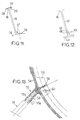
- the blade root 37 has a single bracket 38 transverse and on one side of the running part 19 of dawn, and this leg 38 is constituted by the stacking of the extensions of the layers of fibers of laminated upper and lower surfaces and layers of fibers from complementary stacks as previously described, as well as a layer of glass fibers in the support and fixing area against the central body 14.
- FIG. 5 Another difference from the example of Figures 5 to 7 is that it is provided, between the two legs of laminate and transverse fixing 28 and 29, extending in opposite directions from each other at the tip of blade 18, a laminated closure sole 39, consisting of the overlay of a fold of carbon fiber cloth, worms inside the dawn, and two plies of fiber fabric glass outwards, the warp or weft of the folds of fabric being oriented in the transverse direction of legs 28 and 29.
- Figure 12 shows schematically another example of a high-performance dawn in terms of maintenance, because interchangeable, and mechanically, because ensuring better introduction of efforts due to the mode of resumption of the blade root 47 on the central body 44.
- the blade root 47 is presented under the shape of a single mounting bracket laminated in the longitudinal extension of the main part 19 of dawn, and constituted by the superposition of extensions laminated top and bottom surfaces of this running part, with a layer of fiberglass protection on one face of the lug 47 which is fixed removably by a screw-nut assembly shown diagrammatically at 48, simple support on a return tab 45, machined in protruding outwards on the annular wall of the body metallic central 44.
- FIG. 13 partially shows another example of a blade which, like that of FIG. 12, has a blade root 57 arranged in a laminated leg made of same way as in the previous examples and in the longitudinal extension of the main part 19 of dawn.
- the draping and molding of the dawn are therefore simplified, due to the simplification of the definition of blade root 57 or 47 of the previous example.
- the dawn of the figure 13 differs essentially from that of figure 12 by the fact that its fixing leg of the blade root 57 is introduced and retained in a yoke 55 projecting towards the exterior on the annular wall of the central body 54. This yoke 55 ensures the introduction and passage of more homogeneous efforts in the dawn.
- Clevis 55 is such that one of its legs 55a is thinner than the other 55b.
- the thinnest tab 55a secures the blade by a screw-nut assembly represented schematically by the center line 58, while the thickest tab 55b allows the transmission of forces with greater rigidity.
- the central body 54 is not more metallic but molded by hot compression of a composite material made of short glass fibers embedded in a thermosetting matrix of vinylester type, the rectifier body 54 being produced in a single part after a polymerization cycle lasting 3 minutes for example at a temperature of 120 ° C., under a pressure of compaction of the order of 10 MPa.
- each rib 56 provides rigidity suitable for the rectifier body 54 at the connection a corresponding yoke 55 to this body 54, that is to say at the place of passage of the forces towards the corresponding dawn.
- the blades each injection molded according to the "RTM” process, are individually attached to a rectifier body metallic (machined from aluminum alloy for example) or composite (compression molded in fiber reinforced resin short), the connection between each blade and the body of rectifier which can be carried out by screw-nut assemblies ensuring correct tightening as well as a possibility of disassembly for a possible maintenance operation (change of dawn).
- a rectifier body metallic machined from aluminum alloy for example
- composite compression molded in fiber reinforced resin short
- any composite dawn whose part current has its upper and lower parts including each at least one layer of stiffened reinforcing fibers by a synthetic agglomeration resin, can be molded by the method of the invention.
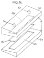
- This mold 61 essentially comprises two upper half-molds 61a and lower 61b, having each one of two internal fingerprints 62a and 62b which are complementary to each other to form an imprint corresponding to the aerodynamic profile of the current part of dawn, as well as the profile of his foot and his toe, when the two half-molds 61a and 61b are closed one on the other, by means of clamping and sealing not described because well known, the centering being ensured by centering pins, also well known (not shown), and the mold has a vacuum outlet 63, opening into the mold footprint and connected by a fitting to a vacuum (not shown) as well as an injection socket resin 64 also opening into the mold cavity.
- the imprint 62a of the upper half-mold 61a may correspond to the shape of the dawn upper surface in his foot, his toe and his running part, and, likewise, the imprint 62b of the lower half-mold 61b may correspond in the shape of the lower surface of dawn, in its three parts, so that the parting line of the half-molds 61a and 61b passes through the leading and trailing edges of the dawn.
- a class injection resin called "at 180 ° C.” leads to the use of a metallic mold 61, for example machined from aluminum alloy.
- the injection resin used is of the so-called "120 ° C” class
- the mold 61 can be made of composite material, using a casting resin loaded with metallic particles. This mold made of composite material can be obtained by overmolding of a blade model, for example metallic.
- the manufacture of a dawn begins with the realization a preform 65 produced by draping the one or more prepared layers, for example precut, of reinforcement of nature, orientation, and predetermined dimensions, as described above, around the core 20 of foam.
- This core 20 is firstly prepared by compression a foam bar in a mold giving it its shape and surface compaction.
- This core mold can be a specific mold, also of classical structure, in two parts with complementary internal fingerprints, the two parts being pressed against each other and around the foam bread, until it comes into abutment against each other by the joint plane.
- the foam core 20 can also be formed by compression of a bread foam in the injection mold, in which the imprints 62a and 62b will have been previously fitted with models, for example in lead, in the shape and dimensions of linings of lower and upper surfaces to surround the core.
- the surface densification of the core 20 can be ensured by cold compression of the foam bread, in which case it is then necessary to return the surface of the nucleus impervious to the resin used, to prevent migration of the latter in the foam core. This is ensured in surrounding the core with a film of heat shrinkable material welded and shaped around the core by air blowing hot.
- the foam core being prepared it is sheathed with reinforcing fibers, essentially dry, for example draping around the core the braids of fibers, sheets of fibers and plies of fiber fabric previously cut to dimensions required, when draping is done with layers of fibers of predefined nature and orientation, according to the examples described above.
- reinforcing fibers essentially dry, for example draping around the core the braids of fibers, sheets of fibers and plies of fiber fabric previously cut to dimensions required, when draping is done with layers of fibers of predefined nature and orientation, according to the examples described above.
- Maintaining place of the different layers of fibers of the draping is ensured by a light gluing using a lacquer in aerosol, or by using at least one layer of reinforcing fibers lightly coated with an epoxy binder thermoreversible now the fibers of the same layer of reinforcement between them.
- the blade preform 65 consisting of core surrounded by the sheath of reinforcing fibers formed of the or layers of fibers that comprise the completed dawn, is then deposited in the open injection mold 61, of which the surfaces of the imprints 62a and 62b of the two parts of mold 61a and 61b were previously prepared for ensure good release.
- This preparation can consist to cover each of the imprints 62a and 62b with a film of PTFE adhesive, such as that sold under the brand NYTOFLON, the joint plane of the two half-molds 61a and 61b being covered for example with a release agent of the type marketed under the name FREEKOTE 700.
- the mold 61 is then closed tight around the preform 65, and it is evacuated by the outlet 63.
- the mold 61 is then put in an oven for heating until reaching the heart of the mold 61 a temperature corresponding to the temperature for which the injection resin used will be liquid and lowest viscosity.
- the mold is then taken out of the oven and the injection is made by socket 64, under pressure, after preparation of the matrix resin (mixing and degassing).
- the resin Before injection into the mold 61 through socket 64, the resin can be heated in a suitable heat exchanger, and possibly its reheating to achieve a sufficiently low viscosity for its injection can be completed in a cut throat in the mold 61 and serving to receive the resin before its migration through the fiber layers of the preform 65.
- the mold 61 can be placed vertically during the injection of the resin, the injection port 64 being disposed towards the bottom and the vacuum outlet 63 upwards, so that the resin ensures good impregnation of the fiber layers of preform 65 from bottom to top, removing particles residual air from the preform 65, to obtain an absence porosity in the injected blade.
- the mold 61 containing the preform 65 impregnated with injected resin is laid out flat in an oven or in a press with a heating plate for the polymerization phase. This phase is followed a cooling phase of the mold and its contents, then the opening of the mold and demolding of the blade.
- the temperature of the mold at the start of injection is between approximately 62 ° C and approximately 59 ° C, and at the end of injection between approximately 50 ° C and 55 ° C, in order to maintain the resin at a temperature of the order of 60 ° C for which it is liquid and has a low viscosity, not greater than 100 mPa.s.
- the injection pressure of the resin, at the start of the injection phase is of the order of 0.75 x 10 5 Pa to 10 5 Pa , and at the end of injection, of the order of 2.5 ⁇ 10 5 Pa to 3 ⁇ 10 5 Pa.
- the polymerization cycle can be of 1 hour 30 minutes at 80 ° C., and the cooling is slow. in ambient atmosphere.
- each blade incorporates metallic elements electrically conductive, so as to ensure continuity electric of the central body 14 and the box of rear transmission which it encloses up to the inserts in the annular wall of the vein 6.
- These metallic elements electrically conductive can be a tinsel of copper or a bronze or copper mesh incorporated in the topping and extending to the foot and the end blade and the mounting lugs of these parts, up to holes for the passage of the screw-nut fixing assembly dawn.
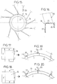
- FIG 15 shows another example in which the ten blades 69 and the annular central body 74 of the rectifier are in one piece made of composite materials and molded in a single resin injection according to the process RTM.
- the running part and the tip of each blade 69 are identical to the corresponding parts of the blades of previous examples but the foot of each dawn 69 is in the longitudinal extension of the corresponding blade and is found linked to the central body 74 by connecting layers in reinforcing fibers which are of the same nature as the layers of reinforcing fibers of the lower and upper surfaces of the blades 69, and agglomerated by the same resin, used for the only injection step.
- the central body 74 has a laminate structure consisting of a stack of layers reinforcing fibers also of the same kind or of a similar in nature to the lower and upper parts vanes 69, and agglomerated by the same injection resin.
- FIG 16 shows that each blade 69 is connected on the whole rope of his foot on the side wall 75 of the central body 74, this wall 75 being thicker in its upstream part extended, at its upstream axial end, by an internal radial flange 76 for taking up the gearbox rear transmission, while the downstream part of the wall lateral 75 is thinner and extends at its end downstream axial, by an internal radial fallen edge 77 likewise thickness, therefore thinner than the upstream flange 76.
- the thinnest section of the annular wall 75 and the fallen edge 77 corresponds to a stack of ten plies of carbon fiber fabric to chain oriented in the circumferential direction of the central body 74, the four internal folds like the four of the stack being in balanced fabric, and in the thickest part of the body 74, corresponding to the flange 76 for recovery of the rear gearbox and at the upstream part of the side wall 75, this stack is completed with four plies of carbon fiber fabric having the same orientation, the two outer folds of this complementary stacking being in balanced fabric.
- the draping of the body of rectifier 74 further comprises two superimposed braids and at 60 ° of unidirectional carbon fibers and arranged under the four outer plies of balanced fabric.
- the section in its thinnest running part and in the downstream edge 77 is given by a stack, from the inside outward, of a fold of carbon fabric balanced and 0 ° (chain oriented in the circumferential direction of body 74) then of two superimposed layers of unidirectional carbon fibers oriented in the same direction, then four overlapping folds of carbon fibers, the two central pleats of which are made of fabric balanced, with the same orientation for these four folds, then again of two superimposed layers of unidirectional fibers carbon with the same orientation, and finally an outer fold of balanced carbon fabric at 0 °.
- this stack is completed, towards outside, and as in the previous example, by four overlapping plies of carbon fiber fabric oriented at 0 °, including two plies in balanced fabric, and, also as in the previous example, at each blade root, two superimposed and 60 ° braids of unidirectional carbon fibers are integrated before the last four layers of the basic stack.
- this unibody rectifier assembly includes the production of a preform 65 as described above for each of the blades 69, by cladding a core foam with the layer or layers of reinforcing fibers each dawn, as well as the realization of a preform of the body with a layer of reinforcing fiber layers by example according to one of the two aforementioned examples.
- the process of manufacturing therefore involves the formation and compaction of foam cores for the blades 69, the draping of the blades on these cores compacted to form blade preforms 65, draping layers of reinforcing fibers to form the preform of the rectifier body 74 around a tool which will be incorporated into the injection mold, then setting place of the different preforms of the blades 69 and of the body central 74 in the injection mold, and the draping of folds of connection between the preforms of the blades and that of the body, then sealing the injection mold tightly, placing it under vacuum and injection of a liquid resin under pressure, the injection being substantially central while the vacuum is made in the mold cavities from the tips dawn, this injection stage ensuring good migration resin for impregnating all layers of reinforcing fibers of the different preforms, and being followed a polymerization cycle, itself followed by a cooling and finally demolding.
- FIGS. 17 and 18 represent in plan two folds which can be placed in successions alternatives to ensure continuity of geometry monobloc rectifier and good transmission of forces between the blades 69 and the body 74.
- Figures 19 and 20 schematically represent the mode of placement of the folds in Figures 17 and 18 respectively.
- the fold 78 of carbon fiber fabric of Figure 17 has its central part which is applied against the lateral face external of the annular part 75 of the body preform 74, between two consecutive blade preforms 65, and this fold 78 has an upper flap a and a lower flap b, which are rectangular and transverse, and apply respectively the first for example against the lower surface of the foot of a preform 65 and the second against the upper surface of the foot of an adjacent preform 65, and this fold 78 comprises also two side flaps c and d, which are rectangular and longitudinal, the first c with a width equal to the radial dimension of the flange 76, and the second d of a width equal to the radial dimension of the fallen edge 77, and these flaps c and d are folded respectively on the flange 76 and on the fallen edge 77 extending, at their ends located on the sides of the flap a, substantially up to the upper surface of the foot of the preform 65 against the lower surface of which component a is applied.
- the next fold 79 also has its part central applied against the external surface of the part annular 75 of the preform of the body 74, between the two same preforms 65, and it has two parts a 'and b' rectangular and transverse, of the same dimensions as the flaps a and b of fold 78, as well as two side flaps c ' and of, of the same dimensions as the flaps c and d of the fold 78, but such that the free ends of the flaps c 'and d' extend on either side of shutter b ', and not on either side and other side of the shutter has as is the case for the ends flaps c and d of fold 78.
- Figure 20 shows that the components a 'and b' are applied respectively as the flaps a and b, and on top of them, and that flaps c 'and d are folded over the flange 76 and the dropped edge 77, partially covering, with a shift in direction circumferential, the flaps c and d of the previous fold 78, shutters c 'and d extending this time to the level of the lower surface of preform 65 against the upper surface of which components b and b 'are applied.
Landscapes
- Engineering & Computer Science (AREA)
- Mechanical Engineering (AREA)
- Chemical & Material Sciences (AREA)
- General Engineering & Computer Science (AREA)
- Composite Materials (AREA)
- Materials Engineering (AREA)
- Aviation & Aerospace Engineering (AREA)
- Ceramic Engineering (AREA)
- Structures Of Non-Positive Displacement Pumps (AREA)
Claims (31)
- Leiteinrichtungsschaufel für eine stromlinienförmige Gegendrehmomentvorrichtung für Drehflügler-Luftfahrzeuge, wie z.B. für Hubschrauber,wobei die Schaufel (9) dazu bestimmt ist, in einen Leiteinrichtungsstator (8) integriert zu werden, der seinerseits in einem Kanal (6) mit einer Achse (X-X) befestigt ist, die im wesentlichen quer zur Längsachse des Luftfahrzeugs verläuft und einen Luftfahrzeug-Heckteil (2) durchläuft, in dem der Kanal (6) durch eine ringförmige Wand (6a) begrenzt ist, wobei im Kanal (6) darin im wesentlichen koaxial ein Rotor (7) angebracht ist, der durch einen im wesentlichen koaxial im Kanal (6) angebrachten Mechanismus (14a) drehangetrieben wird, so daß die Drehung des Rotors (7) eine Luftströmung im Kanal (6) erzeugt, wobei der Leiteinrichtungsstator (8) im Kanal (6) in bezug auf die Luftströmungsrichtung strömungsabwärts vom Rotor (7) befestigt ist und außerdem einen ringförmigen, den Drehantriebsmechanismus (14a) umgebenden Zentralkörper (14) enthält,wobei die Schaufel (9) einen Strömungsteil (19) mit aerodynamischem Profil aufweist, der die Luftströmung strömungsabwärts vom Rotor (7) zur Achse (X-X) des Kanals (6) hin leitet und der sich zwischen einem Schaufelfuß (17; 17'; 37; 47; 57) und einem Schaufelkopf (18) an den Enden des Strömungsteils (19) erstreckt, wobei die Schaufel (9) mit dem Fuß (17; 17'; 37; 47; 57) und dem Kopf (18) am Zentralkörper (14) bzw. an der ringförmigen Wand (6a) des Kanals (6) befestigt ist, um den Drehantriebsmechanismus (14a) und den Rotor (7) im Kanal (6) zu tragen, dadurch gekennzeichnet, daß die Schaufel aus Verbund ist und ihr Strömungsteil (19) einen Saugseitenteil (21) und Druckseitenteil (22) aufweist, die geschichtet sind und jeweils einen Stapel aus wenigstens drei Schichten von Verstärkungsfasern, im wesentlichen aus Carbon, aufweisen, die durch ein synthetisches wärmeaushärtendes Preßharz versteift sind, wobei die innere und/oder die äußere Schicht des Stapels zwei Anordnungen aus im wesentlichen in einer Richtung verlaufenden und in bezug zueinander unter etwa 30° bis etwa 70° und in bezug auf die Längsachse der Schaufel (9) entlang ihrer Spannweite im wesentlichen symmetrisch ausgerichteten Fasern enthalten, und die Zwischenschicht eine Anordnung von im wesentlichen in einer Richtung ausgerichteten Fasern entlang der Längsachse der Schaufel (9) enthält, wobei der Fuß (17; 17'; 37; 47; 57) und/oder der Kopf (18) der Schaufel wenigstens einen Befestigungslappen (25, 26, 28, 29) aufweisen, der einen Stapel von Verlängerungen der Verstärkungsfaserschichten des Druckseitenteils (22) und/oder Saugseitenteils (21) des Strömungsteils (19) mit wenigstens einem komplementären Stapel mit einer Mittelschicht aus im wesentlichen in einer Richtung verlaufenden Verstärkungsfasern enthält, die im wesentlichen parallel zu denjenigen der Zwischenschicht im Fuß (17; 17'; 37; 47; 57) oder im Kopf (18) der entsprechenden Schaufel ausgerichtet sind, und zwischen zwei Lagen von gleichgeordnetem Gewebe aus Verstärkungsfasern, deren Kette im wesentlichen parallel zu den in einer Richtung verlaufenden Fasern der Mittelschicht ausgerichtet ist.
- Schaufel nach Anspruch 1, dadurch gekennzeichnet, daß ihre geschichteten Teile (21, 22, 23, 24, 25, 26, 28, 29) einen Anteil an Verstärkungsfasern von etwa 40 % bis etwa 60 % im Volumen haben.
- Schaufel nach einem der Ansprüche 1 und 2, dadurch gekennzeichnet, daß die innere Schicht des Stapels einen aus den folgenden Aufbauten gewählten Aufbau hat: ein Gewebe aus im wesentlichen in einer Richtung entlang der Längsachse der Schaufel (9) ausgerichteten Verstärkungsfasern und wenigstens eine Lage aus Gewebe, das bezüglich der im wesentlichen entlang der Längsachse der Schaufel (9) ausgerichteten Kette im wesentlichen zu 90 % aus Carbonfasern und bezüglich dem Gewebeschuß im wesentlichen zu 10 % aus Glas- oder Carbonfasern besteht.
- Schaufel nach einem der Ansprüche 1 bis 3, dadurch gekennzeichnet, daß die innere und/oder äußere Schicht des geschichteten Saugseitenteils (21) und Druckseitenteils (22) ihres Strömungsteils (19) einen unter den folgenden Aufbauten gewählten Aufbau hat: ein Längsgeflecht aus Carbonfasern, die zwischen etwa 30° bis 70° in bezug zueinander und in bezug auf die Längsachse der Schaufel (9) im wesentlichen symmetrisch ausgerichtet sind, und wenigstens zwei übereinander angeordnete Decken aus Carbonfasern, die im wesentlichen in einer Richtung verlaufen und im wesentlichen symmetrisch mit etwa ± 15° bis etwa ± 35° in bezug auf die Längsachse der Schaufel (9) ausgerichtet sind.
- Schaufel nach einem der Ansprüche 1 bis 4, dadurch gekennzeichnet, daß die Zwischenschicht des geschichteten Saugseitenteils (21) und Druckseitenteils (22) des Strömungsteils (19) eine aus den folgenden Aufbauten gewählten Aufbau hat: ein Geflecht aus im wesentlichen in einer Richtung entlang der Längsachse der Schaufel (9) ausgerichteten Verstärkungsfasern, eine Übereinanderlagerung wenigstens zweier Decken aus im wesentlichen in einer Richtung entlang der Längsachse der Schaufel (9) ausgerichteten Verstärkungsfasern und eine Übereinanderlagerung wenigstens zweier Lagen aus zumindest einem Gewebe, das bezüglich der im wesentlichen entlang der Längsachse der Schaufel (9) ausgerichteten Kette im wesentlichen zu 90 % aus Karbonfasern und bezüglich des Gewebeschusses im wesentlichen zu 10 % aus Glas- oder Carbonfasern besteht.
- Schaufel nach einem der Ansprüche 1 bis 5, dadurch gekennzeichnet, daß die Mittelschicht der Fasern des komplementären Stapels in Höhe des Fußes (17) und/oder des Kopfes (18) der Schaufel einen aus den folgenden Aufbauten gewählten Aufbau enthält: wenigstens eine Decke aus in einer Richtung verlaufenden Fasern und wenigstens eine Lage aus Gewebe, das bezüglich der Kette im wesentlichen zu 90 % aus Carbonfasern und bezüglich des Schusses zu 10 % aus Glas- oder Carbonfasern besteht.
- Schaufel nach einem der Ansprüche 1 bis 6, dadurch gekennzeichnet, daß in Höhe des Fußes (17) der Schaufel (9) der komplementäre Stapel einen Stapel aus wenigstens zwei Lagen aus Verstärkungsfaser-Gewebe, dessen Kette oder Schuß im wesentlichen parallel zur Längsachse der Schaufel (9) ausgerichtet ist, und aus wenigstens zwei gekreuzten Lagen aus Verstärkungsfaser-Gewebe enthält, dessen Kette oder Schuß im wesentlichen unter 45 % gegenüber der Längsachse der Schaufel (9) ausgerichtet ist.
- Schaufel nach einem der Ansprüche 1 bis 7, dadurch gekennzeichnet, daß der Stapel des Fußes (17) und/oder des Kopfes (18) der Schaufel (9) wenigstens eine Schicht aus Glasfasern in denjenigen Zonen enthält, die mit dem Zentralkörper (14) bzw. der ringförmigen Wand (6a) des Kanals (6) in Berührung kommen.
- Schaufel nach einem der Ansprüche 1 bis 8, dadurch gekennzeichnet, daß der Kopf (18) und/oder der Fuß (17) der Schaufel (9) zwischen zwei quer verlaufenden, geschichteten Befestigungslappen (28, 29), die sich in zueinander entgegengesetzten Richtungen erstrecken, eine geschichtete Abschlußsohle (39) enthalten, die einen Stapel aus wenigstens einer Gewebelage aus Verstärkungsfasern zum Inneren der Schaufel (9) hin und wenigstens eine Gewebelage aus Glasfasern zum Äußeren der Schaufel (9) hin aufweist, wobei die Kette oder der Schuß der Gewebelagen im wesentlichen entsprechend der Querrichtung der Befestigungslappen (28, 29) ausgerichtet ist.
- Schaufel nach einem der Ansprüche 1 bis 9, dadurch gekennzeichnet, daß wenigstens ein Befestigungslappen (25, 26, 28, 29) des Fußes (17) und/oder des Kopfes (18) der Schaufel in bezug auf den Saugseitenteil (21) oder den Druckseitenteil (22) der Schaufel (19) gewölbt ist, die er verlängert, und sich oberhalb bzw. unterhalb des Saugseitenteils (21) bzw. des Druckseitenteils (22) erstreckt, wobei er in einer Weise gewölbt und/oder geneigt ist, die im wesentlichen der Krümmung einer Oberfläche des Zentralkörpers (14) oder der Seitenwand (6a) des Kanals entspricht, auf welcher er befestigt werden soll, und/oder derart, daß die Schaufel (9) gegenüber der in bezug auf die Achse (X-X) des Kanals (6) radialen Richtung geneigt und/oder von ihrem Fuß (17) zu ihrem Schaufelkopf (18) und von der Strömungsoberseite zur Strömungsunterseite im Kanal (6) gepfeilt ist.
- Schaufel nach Anspruch 10, dadurch gekennzeichnet, daß wenigstens ein Befestigungslappen (25, 26) des Schaufelfußes (17') einen im wesentlichen radial in bezug auf die Achse (X-X) des Kanals (6) geknickten Teil (34) zur Stützung und Befestigung an einem radialen Befestigungsflansch des Zentralkörpers (14) aufweist.
- Schaufel nach einem der Ansprüche 1 bis 11, dadurch gekennzeichnet, daß der Schaufelfuß (37) einen einzigen Befestigungslappen (38) aufweist, der sich im wesentlichen quer auf nur einer Seite der Schaufel erstreckt und aus einem Verlängerungen des geschichteten Saugseiten- und Druckseitenteiles des Srömungsteiles (19) der Schaufel enthaltenden Stapel besteht.
- Schaufel nach einem der Ansprüche 1 bis 10, dadurch gekennzeichnet, daß der Schaufelfuß (47) einen Befestigungslappen aufweist, der sich im wesentlichen in der Längsverlängerung des Strömungsteils (19) erstreckt und bevorzugt in lösbarer Weise unter einfacher Abstützung an einem nach außen vom Zentralkörper (44) der Leiteinrichtung abstehenden Aufnahmelappen (45) befestigt (48) werden soll.
- Schaufel nach Anspruch 13, dadurch gekennzeichnet, daß der Aufnahmelappen (55a) einer von zwei Lappen (55a, 55b) einer Aufnahmekappe (55) ist, die vom Zentralkörper (54) nach außen absteht und in welcher der Befestigungslappen (57) des Schaufelfußes in Eingriff steht und gehalten (58) ist.
- Schaufel nach einem der Ansprüche 10 bis 14, dadurch gekennzeichnet, daß der oder die Befestigungslappen (28, 29) des Schaufelkopfes (18) in einer lösbaren Weise durch Verschraubung (30) an einem an der ringförmigen Wand (6a) des Kanals (6) angebrachten Einsatz (31) befestigt ist/sind und der oder die Befestigungslappen (25, 26) des Schaufelfußes (17) durch Vernietung oder Verschraubung (27) am Zentralkörper (14) befestigt ist/sind.
- Schaufel nach einem der Ansprüche 1 bis 15, dadurch gekennzeichnet, daß sie aus Vollmaterial ist.
- Schaufel nach einem der Ansprüche 1 bis 15, dadurch gekennzeichnet, daß sie hohl ist.
- Schaufel nach einem der Ansprüche 1 bis 15, dadurch gekennzeichnet, daß das Saugseitenteil (21) und das Druckseitenteil (22) geschichtete Verkleidungen darstellen, die eine steife Schale bilden, die einen aus leichtem, wabenförmigen synthetischen Material oder aus Schaummaterial bestehenden Kern (20) umgibt, der vorzugsweise eine verfestigte und/oder gegenüber dem Preßharz der geschichteten Verkleidungen (21, 22) dicht ausgeführte äußere Oberfläche hat.
- Leiteinrichtung für eine stromlinienförmige Gegendrehmomentvorrichtung für Drehflügler-Luftfahrzeuge, wie z.B. für Hubschrauber,wobei die Leiteinrichtung (8) dazu bestimmt ist, in einem Kanal (6) mit einer Achse (X-X) befestigt zu werden, die im wesentlichen quer zur Längsachse des Luftfahrzeuges verläuft und einen Luftfahrzeug-Heckteil (2) durchläuft, in dem der Kanal (6) durch eine ringförmige Wand (6a) begrenzt ist, wobei im Kanal (6) darin im wesentlichen koaxial ein Rotor (7) angebracht ist, der durch einen im wesentlichen koaxial im Kanal (6) angebrachten Mechanismus (14a) drehangetrieben wird, so daß die Drehung des Rotors (7) eine Luftströmung im Kanal (6) erzeugt,wobei die Leiteinrichtung (8) im Kanal (6) in bezug auf die Luftströmungsrichtung strömungsabwärts vom Rotor (7) befestigt ist und einen ringförmigen, den Drehantriebsmechanismus (14a) umgebenden Zentralkörper (44; 54; 74) sowie Schaufeln (9; 69) enthält, die jeweils einen Strömungsteil (19) mit aerodynamischem Profil aufweisen, der die Luftströmung strömungsabwärts vom Rotor (7) zur Achse (X-X) des Kanals (6) hin leitet und der sich zwischen einem Schaufelfuß (17; 47; 57) und einem Schaufelkopf (18) an den Enden des Strömungsteils (19) erstreckt, wobei die Schaufel (9; 69) mit dem Fuß (17; 47; 57) und dem Kopf (18) am Zentralkörper (44; 54; 74) bzw. an der ringförmigen Wand (6a) des Kanals (6) befestigt ist, um den Drehantriebsmechanismus (14a) und den Rotor (7) im Kanal (6) zu tragen, dadurch gekennzeichnet, daß der ringförmige Zentralkörper (44; 54; 74) der Leiteinrichtung (8) eine Seitenwand (75) von zylindrischer oder zylinderkonischer Form mit im wesentlichen axialdrehsymmetrischer Außenfläche, mit der die Schaufeln (9; 69) aus Verbund mit Saugseitenteil (21) und Druckseitenteil (22) ihres Strömungsteils, das jeweils wenigstens eine Schicht aus durch ein synthetisches Preßharz versteiften Verstärkungsfasern enthält, über ihren Fuß (17; 47; 57) verbunden sind, sowie einen radial nach innen vorstehenden Flansch (76) vorzugsweise an einem seiner beiden axialen Enden zur Verbindung mit dem Drehantriebsmechanismus (14a) und einen radial nach innen vorstehenden Versteifungssaum (77) vorzugsweise am anderen axialen Ende aufweist.
- Leiteinrichtung nach Anspruch 19, dadurch gekennzeichnet, daß jede Schaufel (9) einzeln in lösbarer Weise auf dem Zentralkörper (44; 54) aufgesetzt ist.
- Leiteinrichtung nach Anspruch 20, dadurch gekennzeichnet, daß der Zentralkörper (44) aus Metall ist und Aufnahmelappen (45) aufweist, die nach außen von seiner Seitenwand abstehen und an denen jeweils der Fuß (47) einer Schaufel befestigt ist, die einen Befestigungslappen im wesentlichen in der Verlängerung ihres Strömungsteils aufweist.
- Leiteinrichtung nach Anspruch 20, dadurch gekennzeichnet, daß der Zentralkörper (54) aus einem Verbundwerkstoff ausgeführt ist, der durch Warmpressung geformt wird und kurze Verstärkungsfasern, vorzugsweise aus Glas, enthält, die in einer wärmeaushärtenden Matrix, vorzugsweise vom Vinylester-Typ, eingelassen sind, und für jede Schaufel eine Kappe (55), die nach außen von der ringförmigen Seitenwand vorsteht und in der der Fuß (57) der Schaufel gehalten (58) ist, sowie eine Verstärkungsrippe (56) aufweist, die nach innen von der genannten Wand im wesentlichen in Höhe der Kappe (55) vorsteht.
- Leiteinrichtung nach Anspruch 19, dadurch gekennzeichnet, daß der Zentralkörper (74) und die Schaufeln (69) aus einem einzigen Teil aus Verbundwerkstoff bestehen, wobei der Fuß jeder Schaufel (69) in Längsrichtung die entsprechende Schaufel (69) verlängert und mit dem Zentralkörper (74), der einen Stapel von Schichten aus Verstärkungsfasern enthält, die im wesentlichen von gleicher Beschaffenheit wie diejenigen der Schaufeln (69) sind und durch das gleiche Harz verpreßt sind, durch Verbindungsschichten (78, 79) aus Verstärkungsfasern, die im wesentlichen von gleicher Beschaffenheit wie diejenigen der Schaufeln (69) sind und auch mit dem gleichen Harz verpreßt sind, verbunden ist.
- Verfahren zur Herstellung einer Schaufel (9) einer Leiteinrichtung (8), wobei die Schaufel (9) aus Verbund ist und am Saugseitenteil (21) und am Druckseitenteil (22) ihres Strömungsteils jeweils wenigstens eine Schicht aus durch ein synthetisches Verpressungsharz versteiften Verstärkungsfasern enthält, dadurch gekennzeichnet, daß es die Schritte umfaßt, die darin bestehen, die Schaufel (9) durch Spritzen in einer geschlossenen Form (61) und unter Druck aus dem synthetischen Harz zu formen, das ein in einer im wesentlichen flüssigen, wärmeaushärtenden Vorform (65) in die Form (61) eingebrachtes Spritzharz ist und vorher mit Hilfe von Schichten aus Verstärkungsfasern, im wesentlichen aus Carbon, im wesentlichen in die Gestalt der Schaufel (9) gebracht wird.
- Verfahren nach Anspruch 24, dadurch gekennzeichnet, daß es die Schritte umfaßt, die bestehen im:Aufbereiten der Anordnung von Gewebelagen und/oder Decken und/oder Geflechten aus Verstärkungsfasern in für die Erzeugung der Schaufel (9) notwendige Abmessungen,Streckziehen der vorbereiteten Elemente gemäß einer für die Erzeugung der Schaufel (9) definierten Streckziehung um einen Kern (20) aus vorher geformten synthetischen Leichtmaterial, um eine Schaufelvorform (65) mit Kern (20) zu realisieren, der mit einer Hülle aus Verstärkungsfasern umgeben ist,Anordnen der Vorform (65) in der Spritzform (61) vom Typ mit wenigstens zwei komplementären Teilen (61a, 61b) mit komplementären Innenausformungen (62a, 62b) entsprechend der Gestalt der Schaufel (9),Schließen der Form (61) in abdichtender Weise und deren Setzen unter Unterdruck,Einspritzen eines wärmeaushärtenden Harzes unter Druck in die Form (61) bei einer Einspritztemperatur, bei der das Harz im wesentlichen flüssig und von niedriger Viskosität ist, vorzugsweise nicht höher als 100 mPa·s und bei der eine Tränkung aller Verstärkungsfaserschichten gewährleistet ist,Ausführen eines Polymerisationszyklus des Harzes sodann nach Abkühlung der Form (61) und ihres Inhalts,Öffnen der Form (61) und Herausheben der Schaufel (9).
- Verfahren nach Anspruch 25, dadurch gekennzeichnet, daß es auch einen Schritt des Beschichtens eines wärmereversiblen Epoxyd-Binders auf den Gewebelagen und/oder Decken und/oder Geflechten aus Verstärkungsfasern der Streckziehung umfaßt.
- Verfahren nach einem der Ansprüche 25 und 26, dadurch gekennzeichnet, daß es den Schritt umfaßt, der darin besteht, einen Kern (20) zu formen, indem ein Schaumkuchen in eine Form gepreßt und dieser oberflächlich verdichtet wird.
- Verfahren nach Anspruch 27, dadurch gekennzeichnet, daß es den Schritt umfaßt, der darin besteht, die Außenfläche des Kerns (20) gegen das Spritzharz vor der Streckziehung dicht zu machen.
- Verfahren nach Anspruch 28, dadurch gekennzeichnet, daß es darin besteht, die Oberfläche des Kerns (20) gegen das Harz durch Aufbringung einer auf den hinterher wärmegeformten Kern (20) aufgeschweißten und wärmeeinziehbaren Verkleidung um den Kern (20) dicht zu machen.
- Verfahren nach Anspruch 28, dadurch gekennzeichnet, daß es darin besteht, die Oberfläche des Kerns (20) gegen das Harz durch oberflächliche, warm abbindende Verdichtung des Schaumkuchens bei seiner Pressung dicht zu machen.
- Verfahren zur Herstellung einer Leiteinrichtung (8), deren ringförmiger Zentralkörper (74) und Schaufeln (69) aus einem einzigen Stück aus Verbundmaterial bestehen, dadurch gekennzeichnet, daß es die Schritte umfaßt, die bestehen im:Verdichten eines Kerns (20) aus wabenförmigem leichten synthetischen Material oder aus Schaummaterial für jede Schaufel (69) der Leiteinrichtung,Realisieren einer Vorform (65) für jede Schaufel (69), indem die vorher für die erforderlichen Abmessungen aufbereiteten Verstärkungsfaserschichten auf den entsprechenden Kern (20) streckgezogen werden,Realisieren einer Vorform des Zentralkörpers (74) der Leiteinrichtung durch Streckziehen und Stapeln verschiedener vorher aufbereiteter Verstärkungsfaserschichten, die er enthält,Einführen der Vorformen (65) der Schaufeln (69) und der Vorform des Leiteinrichtungskörpers (74) in eine Spritzform,Streckziehen von Verbindungsverstärkungsfaserschichten (78, 79) zwischen den Vorformen (65) der Schaufeln und des Leiteinrichtungskörpers (74) in der Spritzform,Schließen der Form in abdichtender Weise, Setzen derselben unter Unterdruck, vorzugsweise über den Kopf der Schaufeln, und Einspritzen eines wärmeaushärtenden Harzes bei einer solchen Einspritztemperatur, daß es eine niedrige Viskosität aufweist und im wesentlichen flüssig ist, danachGewährleisten eines Polymerisationszyklus und schließlich Herausheben der Leiteinrichtung (8).
Applications Claiming Priority (2)
| Application Number | Priority Date | Filing Date | Title |
|---|---|---|---|
| FR9407141 | 1994-06-10 | ||
| FR9407141A FR2721000B1 (fr) | 1994-06-10 | 1994-06-10 | Aube de redresseur en composite, redresseur la comportant, pour dispositif anti-couple à rotor et stator redresseur carénés, et leur procédé de fabrication. |
Publications (2)
| Publication Number | Publication Date |
|---|---|
| EP0686554A1 EP0686554A1 (de) | 1995-12-13 |
| EP0686554B1 true EP0686554B1 (de) | 1999-02-17 |
Family
ID=9464099
Family Applications (1)
| Application Number | Title | Priority Date | Filing Date |
|---|---|---|---|
| EP95401328A Expired - Lifetime EP0686554B1 (de) | 1994-06-10 | 1995-06-08 | Gleichrichterflügel aus Verbundwerkstoff und Richtapparat einer Gegenwirkmoment-Vorrichtung mit einem eingelassenen Heckrotor und ihre Verfahren zur Herstellung |
Country Status (4)
| Country | Link |
|---|---|
| US (2) | US5605440A (de) |
| EP (1) | EP0686554B1 (de) |
| DE (1) | DE69507854T2 (de) |
| FR (1) | FR2721000B1 (de) |
Cited By (1)
| Publication number | Priority date | Publication date | Assignee | Title |
|---|---|---|---|---|
| WO2026047296A1 (fr) * | 2024-08-28 | 2026-03-05 | Safran Aircraft Engines | Ensemble d'aubage à pas variable comprenant un système de récupération de la foudre muni de fibres conductrices |
Families Citing this family (39)
| Publication number | Priority date | Publication date | Assignee | Title |
|---|---|---|---|---|
| JP3641800B2 (ja) * | 2001-02-05 | 2005-04-27 | 株式会社デンソー | スルーイン研削方法 |
| WO2002081305A1 (en) * | 2001-04-04 | 2002-10-17 | R & M Technology, Llc | Helicopter blade and method of manufacture |
| EP1378338A1 (de) * | 2002-07-03 | 2004-01-07 | Ke-Burgmann A/S | Verfahren und Vorrichtung zur Herstellung von Verbundkörpern in einer geschlossenen Form mit einer Innenfolie und dabei verwendete Innenfolie |
| DE10231830A1 (de) * | 2002-07-12 | 2004-01-22 | Röhm GmbH & Co. KG | Schaumstoff mit verdichteter Oberfläche |
| GB0226690D0 (en) * | 2002-11-15 | 2002-12-24 | Rolls Royce Plc | Vane with modified base |
| EP1473131A3 (de) * | 2003-04-30 | 2007-01-03 | Airbus Deutschland GmbH | Verfahren zum herstellen textiler vorformlinge aus textilen halbzeugen |
| US7343048B2 (en) * | 2003-09-18 | 2008-03-11 | Arcsoft, Inc. | Edge based alignment algorithm |
| US20050093188A1 (en) * | 2003-10-29 | 2005-05-05 | Forest Mark L.L. | Binderless preform manufacture |
| US7541807B2 (en) * | 2007-07-19 | 2009-06-02 | Varian, Inc. | Rotor drive apparatus and methods utilizing center-fed radial-outflow gas |
| US8888451B2 (en) * | 2007-10-11 | 2014-11-18 | Volvo Aero Corporation | Method for producing a vane, such a vane and a stator component comprising the vane |
| GB2455785B (en) | 2007-12-21 | 2009-11-11 | Rolls Royce Plc | Annular component |
| US8220496B2 (en) * | 2009-06-04 | 2012-07-17 | National Oilwell Varco, L.P. | Apparatus for reducing turbulence in a fluid stream |
| US8978705B2 (en) | 2009-06-04 | 2015-03-17 | National Oilwell Varco, L.P. | Apparatus for reducing turbulence in a fluid stream |
| JP5434359B2 (ja) * | 2009-08-19 | 2014-03-05 | 株式会社ブリヂストン | 発泡樹脂成形品の製造方法及び製造設備 |
| ES2392617B1 (es) * | 2010-01-15 | 2013-11-21 | Airbus Operations S.L. | Disposición de unión de los cajones laterales de un estabilizador horizontal de cola con un cajón central tubular y procedimiento de fabricación de dicho cajón. |
| US20120312469A1 (en) * | 2010-03-03 | 2012-12-13 | Siemens Aktiengesellschaft | Method and mould for moulding a wind turbine blade |
| ES2445708T3 (es) * | 2010-11-04 | 2014-03-04 | Siemens Aktiengesellschaft | Método para fabricar una pala |
| US9545757B1 (en) | 2012-02-08 | 2017-01-17 | Textron Innovations, Inc. | Composite lay up and method of forming |
| US9308992B2 (en) * | 2012-02-28 | 2016-04-12 | Sikorsky Aircraft Corporation | Helicopter blade retention composite yoke |
| FR2989020B1 (fr) * | 2012-04-05 | 2014-12-12 | Snecma | Procede de fabrication d'une piece epaisse de turbomachine en materiau composite par injection de resine sous pression |
| US9393745B2 (en) * | 2012-05-15 | 2016-07-19 | Hexcel Corporation | Over-molding of load-bearing composite structures |
| WO2014152636A1 (en) | 2013-03-15 | 2014-09-25 | United Technologies Corporation | Selective coating removal or masking for ground path |
| JP6150054B2 (ja) * | 2013-07-02 | 2017-06-21 | 株式会社Ihi | 静翼構造及びこれを用いたターボファンジェットエンジン |
| EP2878433B1 (de) | 2013-11-29 | 2016-04-20 | AIRBUS HELICOPTERS DEUTSCHLAND GmbH | Ummantelte Drehanordnung aus segmentiertem Verbundwerkstoff für Flugzeuge sowie verfahren zu deren Herstellung |
| EP2926984B1 (de) * | 2014-04-03 | 2019-02-20 | Nordex Energy GmbH | Verfahren zum Reparieren eines elektrischen Heizelements eines Windenergieanlagenrotorblatts |
| EP3263910B1 (de) | 2014-05-05 | 2020-01-08 | Horton, Inc. | Schauffel aus verbundwerkstoff für einen modularen axiallüfter und herstellungsverfahren dafür |
| US10005267B1 (en) | 2015-09-22 | 2018-06-26 | Textron Innovations, Inc. | Formation of complex composite structures using laminate templates |
| US10047763B2 (en) * | 2015-12-14 | 2018-08-14 | General Electric Company | Rotor assembly for use in a turbofan engine and method of assembling |
| FR3050759B1 (fr) * | 2016-04-27 | 2020-02-07 | Safran Aircraft Engines | Ensemble de redressement de flux d'air et turbomachine comprenant un tel ensemble |
| EP3424818B1 (de) | 2017-07-06 | 2020-12-30 | AIRBUS HELICOPTERS DEUTSCHLAND GmbH | Rotornabe für einen heckrotor eines drehflügelflugzeugs |
| EP3424817B1 (de) | 2017-07-06 | 2020-09-02 | AIRBUS HELICOPTERS DEUTSCHLAND GmbH | Rotornabe für einen heckrotor eines drehflügelflugzeugs |
| FR3072607B1 (fr) * | 2017-10-23 | 2019-12-20 | Safran Aircraft Engines | Turbomachine comprenant un ensemble de redressement |
| US10889366B2 (en) | 2018-09-21 | 2021-01-12 | Textron Innovations Inc. | Ducted thrusters |
| US11034440B2 (en) | 2019-03-01 | 2021-06-15 | Textron Innovations Inc. | Tail rotor gearbox support assemblies for helicopters |
| US11085470B2 (en) * | 2019-05-31 | 2021-08-10 | Kalsi Engineering, Inc. | Flow conditioning assembly |
| US20210381385A1 (en) * | 2020-06-03 | 2021-12-09 | Honeywell International Inc. | Characteristic distribution for rotor blade of booster rotor |
| EP4361037B1 (de) | 2022-10-28 | 2025-07-30 | AIRBUS HELICOPTERS DEUTSCHLAND GmbH | Drehflügler mit einem heckausleger mit einem gekapselten heckrotor |
| EP4361036B1 (de) | 2022-10-28 | 2024-08-28 | AIRBUS HELICOPTERS DEUTSCHLAND GmbH | Drehflügelflugzeug mit einem heckrotor mit kanalführung, der von einem stator gestützt wird |
| US12576601B2 (en) * | 2024-01-30 | 2026-03-17 | General Electric Company | Composite structure for a turbine engine |
Family Cites Families (14)
| Publication number | Priority date | Publication date | Assignee | Title |
|---|---|---|---|---|
| US2859936A (en) * | 1954-03-03 | 1958-11-11 | Cincinnati Testing & Res Lab | Compressor blade and method of forming same |
| US3057767A (en) * | 1958-04-01 | 1962-10-09 | Poly Ind Inc | Method of making compressor blades |
| FR1531536A (fr) * | 1967-05-22 | 1968-07-05 | Sud Aviation | Hélice ou rotor à pas variable |
| FR1593008A (de) * | 1968-07-11 | 1970-05-25 | ||
| GB1284538A (en) * | 1968-11-19 | 1972-08-09 | Rolls Royce | Blade for a fluid flow machine |
| US4648921A (en) * | 1980-10-02 | 1987-03-10 | United Technologies Corporation | Method of making fiber reinforced articles |
| US4460531A (en) * | 1982-05-10 | 1984-07-17 | The Boeing Company | Composite fiber reinforced propeller |
| FR2534222A1 (fr) * | 1982-10-06 | 1984-04-13 | Aerospatiale | Agencement de rotor de queue a poussee accrue pour aeronef a voilure tournante et dispositif pour accroitre la poussee d'un tel agencement |
| FR2542695B1 (fr) * | 1983-03-18 | 1985-07-26 | Aerospatiale | Helice multipale a pas variable a pale s en materiaux composites demontables individuellement, procede de fabrication de telles pales et pales ainsi realisees |
| US4594761A (en) * | 1984-02-13 | 1986-06-17 | General Electric Company | Method of fabricating hollow composite airfoils |
| US5131604A (en) * | 1991-04-11 | 1992-07-21 | United Technologies Corporation | Helicopter antitorque device |
| US5272869A (en) * | 1992-12-10 | 1993-12-28 | General Electric Company | Turbine frame |
| FR2719552B1 (fr) * | 1994-05-04 | 1996-07-26 | Eurocopter France | Aube de redresseur pour dispositif anti-couple à rotor et stator redresseur carénés d'hélicoptère. |
| FR2719553B1 (fr) * | 1994-05-04 | 1996-07-26 | Eurocopter France | Dispositif anti-couple à rotor arrière et stator redresseur carénés pour hélicoptère. |
-
1994
- 1994-06-10 FR FR9407141A patent/FR2721000B1/fr not_active Expired - Fee Related
-
1995
- 1995-06-06 US US08/466,296 patent/US5605440A/en not_active Expired - Lifetime
- 1995-06-08 DE DE69507854T patent/DE69507854T2/de not_active Expired - Fee Related
- 1995-06-08 EP EP95401328A patent/EP0686554B1/de not_active Expired - Lifetime
-
1996
- 1996-11-21 US US08/749,349 patent/US5855709A/en not_active Expired - Lifetime
Cited By (2)
| Publication number | Priority date | Publication date | Assignee | Title |
|---|---|---|---|---|
| WO2026047296A1 (fr) * | 2024-08-28 | 2026-03-05 | Safran Aircraft Engines | Ensemble d'aubage à pas variable comprenant un système de récupération de la foudre muni de fibres conductrices |
| FR3165869A1 (fr) * | 2024-08-28 | 2026-03-06 | Safran Aircraft Engines | Ensemble d’aubage à pas variable comprenant un système de récupération de la foudre muni de fibres conductrices |
Also Published As
| Publication number | Publication date |
|---|---|
| FR2721000A1 (fr) | 1995-12-15 |
| FR2721000B1 (fr) | 1996-08-23 |
| US5855709A (en) | 1999-01-05 |
| DE69507854D1 (de) | 1999-03-25 |
| EP0686554A1 (de) | 1995-12-13 |
| US5605440A (en) | 1997-02-25 |
| DE69507854T2 (de) | 1999-10-07 |
Similar Documents
| Publication | Publication Date | Title |
|---|---|---|
| EP0686554A1 (de) | Gleichrichterflügel aus Verbundwerkstoff und Richtapparat einer Gegenwirkmoment-Vorrichtung mit einem eingelassenen Heckrotor und ihre Verfahren zur Herstellung | |
| EP2588758B1 (de) | Propellerblatt mit integriertem verbundholm | |
| EP0296014B1 (de) | FVK-Blatt und sein Herstellungsverfahren | |
| EP0604297B1 (de) | Faserverstärkes thermoplastisches Blatt, insbesondere eines eingelassenen Heckrotors und sein Herstellungsverfahren mit Spritzstufe | |
| JP5027309B2 (ja) | 複合材を製造する方法及び風車羽根 | |
| EP0346210B1 (de) | Faserverstärktes Spant, insbesondere eines Luftfahrzeugrumpfs, und sein Herstellungsverfahren | |
| EP1676775B1 (de) | Verfahren und Vorrichtung zur Herstellung eines Gehäuses für einen Hubschrauberrotor | |
| EP4301657B1 (de) | Schaufel mit einer struktur aus verbundwerkstoff und zugehöriges herstellungsverfahren | |
| EP0942174B1 (de) | Radiallüfterrad aus Verbundwerkstoff | |
| FR2740380A1 (fr) | Procede de fabrication d'une pale a pas variable en materiau composite pour rotor d'helicoptere | |
| WO2016030613A1 (fr) | Aube de redresseur en matériau composite pour moteur a turbine a gaz et son procédé de fabrication. | |
| EP4514600A1 (de) | Propellerblatt oder -schaufel mit hohlem verbundfuss | |
| FR2776264A1 (fr) | Pale a pas variable en materiau composite pour rotor d'helicoptere et procede de fabrication d'une telle pale | |
| FR2740378A1 (fr) | Procede de fabrication d'une pale a pas variable en materiau composite pour rotor d'helicoptere, et pale a pas variable pouvant etre obtenue par un tel procede | |
| WO2025027258A1 (fr) | Aube comprenant une structure en matériau composite et un longeron métallique | |
| FR2740379A1 (fr) | Procede de fabrication d'une pale en materiau composite pour rotor d'helicoptere, et pale pouvant etre obtenue par un tel procede | |
| EP4587260A1 (de) | Propellerblatt oder -schaufel mit hohlem verbundfuss | |
| FR3061070A1 (fr) | Procede de realisation d’un panneau auto raidi en materiaux composites et panneau obtenu par ledit procede | |
| FR3134139A1 (fr) | Renfort pour une aube composite d’une turbomachine, comprenant un empilement de plis | |
| EP4514598B1 (de) | Propellerblatt oder -schaufel mit gewickeltem verbundfuss | |
| EP4532319B1 (de) | Schaufel mit einer struktur aus verbundstoff und zugehöriges herstellungsverfahren | |
| EP4448263A1 (de) | Verfahren zur herstellung eines teils, insbesondere eines teils aus einem verbundstoff | |
| EP4514599A1 (de) | Gebläseschaufel oder -flügel mit kreuz- oder sternförmigem verbundfuss | |
| WO2025120277A1 (fr) | Aube creuse ou pale d'hélice creuse en matériau composite à matrice organique | |
| WO2025196382A1 (fr) | Aube en materiau composite avec echasse renforcee |
Legal Events
| Date | Code | Title | Description |
|---|---|---|---|
| PUAI | Public reference made under article 153(3) epc to a published international application that has entered the european phase |
Free format text: ORIGINAL CODE: 0009012 |
|
| AK | Designated contracting states |
Kind code of ref document: A1 Designated state(s): DE GB IT |
|
| 17P | Request for examination filed |
Effective date: 19960425 |
|
| RAP1 | Party data changed (applicant data changed or rights of an application transferred) |
Owner name: EUROCOPTER |
|
| 17Q | First examination report despatched |
Effective date: 19971219 |
|
| GRAG | Despatch of communication of intention to grant |
Free format text: ORIGINAL CODE: EPIDOS AGRA |
|
| GRAG | Despatch of communication of intention to grant |
Free format text: ORIGINAL CODE: EPIDOS AGRA |
|
| GRAH | Despatch of communication of intention to grant a patent |
Free format text: ORIGINAL CODE: EPIDOS IGRA |
|
| GRAH | Despatch of communication of intention to grant a patent |
Free format text: ORIGINAL CODE: EPIDOS IGRA |
|
| GRAA | (expected) grant |
Free format text: ORIGINAL CODE: 0009210 |
|
| AK | Designated contracting states |
Kind code of ref document: B1 Designated state(s): DE GB IT |
|
| REF | Corresponds to: |
Ref document number: 69507854 Country of ref document: DE Date of ref document: 19990325 |
|
| GBT | Gb: translation of ep patent filed (gb section 77(6)(a)/1977) |
Effective date: 19990325 |
|
| ITF | It: translation for a ep patent filed | ||
| PLBE | No opposition filed within time limit |
Free format text: ORIGINAL CODE: 0009261 |
|
| STAA | Information on the status of an ep patent application or granted ep patent |
Free format text: STATUS: NO OPPOSITION FILED WITHIN TIME LIMIT |
|
| 26N | No opposition filed | ||
| REG | Reference to a national code |
Ref country code: GB Ref legal event code: IF02 |
|
| PGFP | Annual fee paid to national office [announced via postgrant information from national office to epo] |
Ref country code: DE Payment date: 20070530 Year of fee payment: 13 |
|
| PG25 | Lapsed in a contracting state [announced via postgrant information from national office to epo] |
Ref country code: DE Free format text: LAPSE BECAUSE OF NON-PAYMENT OF DUE FEES Effective date: 20090101 |
|
| PGFP | Annual fee paid to national office [announced via postgrant information from national office to epo] |
Ref country code: GB Payment date: 20110606 Year of fee payment: 17 |
|
| PGFP | Annual fee paid to national office [announced via postgrant information from national office to epo] |
Ref country code: IT Payment date: 20120616 Year of fee payment: 18 |
|
| GBPC | Gb: european patent ceased through non-payment of renewal fee |
Effective date: 20120608 |
|
| PG25 | Lapsed in a contracting state [announced via postgrant information from national office to epo] |
Ref country code: GB Free format text: LAPSE BECAUSE OF NON-PAYMENT OF DUE FEES Effective date: 20120608 |
|
| PG25 | Lapsed in a contracting state [announced via postgrant information from national office to epo] |
Ref country code: IT Free format text: LAPSE BECAUSE OF NON-PAYMENT OF DUE FEES Effective date: 20130608 |