EP0686540A1 - Abdeckung einer Mittelpufferkupplung für Schienenfahrzeuge - Google Patents
Abdeckung einer Mittelpufferkupplung für Schienenfahrzeuge Download PDFInfo
- Publication number
- EP0686540A1 EP0686540A1 EP95108276A EP95108276A EP0686540A1 EP 0686540 A1 EP0686540 A1 EP 0686540A1 EP 95108276 A EP95108276 A EP 95108276A EP 95108276 A EP95108276 A EP 95108276A EP 0686540 A1 EP0686540 A1 EP 0686540A1
- Authority
- EP
- European Patent Office
- Prior art keywords
- coupling
- hood
- vehicle
- central buffer
- buffer coupling
- Prior art date
- Legal status (The legal status is an assumption and is not a legal conclusion. Google has not performed a legal analysis and makes no representation as to the accuracy of the status listed.)
- Granted
Links
- 230000008878 coupling Effects 0.000 title claims abstract description 29
- 238000010168 coupling process Methods 0.000 title claims abstract description 29
- 238000005859 coupling reaction Methods 0.000 title claims abstract description 29
- 230000006378 damage Effects 0.000 description 5
- 208000027418 Wounds and injury Diseases 0.000 description 4
- 208000014674 injury Diseases 0.000 description 4
- 239000011152 fibreglass Substances 0.000 description 1
- 239000000463 material Substances 0.000 description 1
- 239000002184 metal Substances 0.000 description 1
- 239000004033 plastic Substances 0.000 description 1
- 229920003023 plastic Polymers 0.000 description 1
Images
Classifications
-
- B—PERFORMING OPERATIONS; TRANSPORTING
- B61—RAILWAYS
- B61F—RAIL VEHICLE SUSPENSIONS, e.g. UNDERFRAMES, BOGIES OR ARRANGEMENTS OF WHEEL AXLES; RAIL VEHICLES FOR USE ON TRACKS OF DIFFERENT WIDTH; PREVENTING DERAILING OF RAIL VEHICLES; WHEEL GUARDS, OBSTRUCTION REMOVERS OR THE LIKE FOR RAIL VEHICLES
- B61F19/00—Wheel guards; Bumpers; Obstruction removers or the like
- B61F19/04—Bumpers or like collision guards
-
- B—PERFORMING OPERATIONS; TRANSPORTING
- B61—RAILWAYS
- B61G—COUPLINGS; DRAUGHT AND BUFFING APPLIANCES
- B61G7/00—Details or accessories
- B61G7/14—Safety devices
Definitions
- the invention relates to the cover of a central buffer coupling for rail vehicles, in particular tram vehicles, consisting of a hood which partially covers the central buffer coupling and releases it for coupling if necessary.
- Middle buffer couplings are known in tram vehicles, which are surrounded by a hood made of impermeable plastic material for protection against weather influences.
- hoods of this type offer no protection against injuries caused by the central buffer coupling in the event of accidents with other road users, in particular by the parts protruding beyond its buffer surface, such as the dome horn and sliding parts of the electrical coupling. The hood must also be removed manually before coupling.
- a hood made of metal or glass fiber reinforced plastic which is adapted to the shape of the drive head.
- Such a hood would offer protection against injuries from the central buffer coupling in the event of accidents in the case of slow-moving rail vehicles, such as tram vehicles, but can only be removed manually and when the vehicle is stationary in order to enable coupling.
- the invention has for its object to provide a cover for a central buffer coupling of the generic type, which protects other road users against injury from protruding parts of the central buffer coupling and which can be brought into a position both when the rail vehicle is at a standstill and when it is moving, which enables automatic coupling .
- the hood covers the front of the vehicle and that of the clutch at a distance as a ramming body, the hood having a handlebar on each side, which is connected to rods arranged vertically in the vehicle and simultaneously by a common drive and can be raised and lowered evenly.
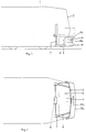
- the tram vehicle 1 has, in a known manner in the end face 2, a free space 3 for receiving a central buffer coupling 4 which projects beyond the end face 2 and which can be pivoted both horizontally and vertically.
- a hood 5 lying in front of the front side 2, which is open at the bottom and whose front side 5a is designed as a ram body in front of the central buffer coupling 4, while the top side 5b covers the distance between the front side 5a and the front side 2.
- the hood 5 is held by links 6 which are arranged on both sides and which have rods mounted vertically in the vehicle 1 7 are connected, these rods 7 being raised and lowered and coupled to a drive 8.
- links 6 which are arranged on both sides and which have rods mounted vertically in the vehicle 1 7 are connected, these rods 7 being raised and lowered and coupled to a drive 8.
- the center buffer coupling 4 is covered by the front 5a of the hood 5 to the outside, so that in the event of an accident, in particular by protruding parts of the center buffer coupling 4, such as a dome horn or sliding parts of the electrical couplings (not shown), no damage or injuries caused.
- a drive 8 is activated, which in the present exemplary embodiment (see FIG. 2) is formed from an electric drive motor with a reduction gear and two horizontally running drive shafts, each of which has a spur gear meshing with a toothing of the associated rod 7 at its outer end exhibit.
- the rods 7 and thus the handlebars 6 together with the hood 5 are raised simultaneously and evenly up to a stop / limit switch.
- the hood 5 is lowered again into the lower position according to FIG. 1 after uncoupling.
Landscapes
- Engineering & Computer Science (AREA)
- Mechanical Engineering (AREA)
- Vibration Dampers (AREA)
- Superstructure Of Vehicle (AREA)
Abstract
Description
- Die Erfindung betrifft die Abdeckung einer Mittelpufferkupplung für Schienenfahrzeuge, insbesondere Straßenbahnfahrzeuge, bestehend aus einer Haube, die die Mittelpufferkupplung teilweise abdeckt und im Bedarfsfall zum Kuppeln freigibt.
- Es sind Mittelpufferkupplungen bei Straßenbahnfahrzeugen bekannt, die zum Schutz gegen Witterungseinflüsse von einer Haube aus regenundurchlässigem plastischem Material umgeben sind. Derartige Hauben bieten aber bei Unfällen mit anderen Verkehrsteilnehmern im Straßenverkehr keinen Schutz gegen Verletzungen durch die Mittelpufferkupplung, insbesondere durch die über deren Pufferfläche vorstehenden Teile, wie Kuppelhorn und Gleitstücke der elektrischen Kupplung. Auch muß zum Kuppeln die Haube vorher manuell entfernt werden.
- Bei Triebwagen, insbesondere Hochgeschwindigkeitszügen, ist es ferner bekannt, die aus der Stirnseite des Fahrzeugs herausragende Mittelpufferkupplung und deren Freiraum im Triebkopf durch eine der Form des Triebkopfes angepaßte Haube aus Metall oder glasfaserverstärktem Kunststoff abzudecken. Eine derartige Haube würde zwar bei langsam fahrenden Schienenfahrzeugen, wie Straßenbahnfahrzeugen, bei Unfällen einen Schutz gegen Verletzungen durch die Mittelpufferkupplung bieten, kann aber nur manuell und bei stehendem Fahrzeug entfernt werden, um ein Kuppeln zu ermöglichen.
- Der Erfindung liegt die Aufgabe zugrunde, eine Abdeckung für eine Mittelpufferkupplung der gattungsgemäßen Art zu schaffen, die andere Verkehrsteilnehmer gegen Verletzung durch vorstehende Teile der Mittelpufferkupplung schützt und die sowohl bei stehendem als auch fahrendem Schienenfahrzeug in eine Lage gebracht werden kann, die ein selbsttätiges Kuppeln ermöglicht.
- Diese Aufgabe wird nach der Erfindung dadurch gelöst, daß die Haube die Stirnseite des Fahrzeugs und die der Kupplung in einem Abstand als Rammkörper abdeckt, wobei die Haube beidseitig je einen Lenker besitzt, die mit senkrecht im Fahrzeug angeordneten Stangen verbunden und durch einen gemeinsamen Antrieb gleichzeitig und gleichmäßig heb- und senkbar sind.
- In der Zeichnung ist ein Ausführungsbeispiel der Erfindung schematisch dargestellt. Es zeigen:
- Fig. 1
- ein Straßenbahnfahrzeug mit einer Abdeckung der Mittelpufferkupplung in Seitenansicht,
- Fig. 2
- das Fahrzeug gemäß Fig. 1 in Draufsicht.
- Das Straßenbahnfahrzeug 1 besitzt in bekannter Weise in der Stirnseite 2 einen Freiraum 3 zur Aufnahme einer die Stirnseite 2 überragenden Mittelpufferkupplung 4, die sowohl horizontal schwenkbar als auch vertikal beweglich ist. Im Bereich des Freiraums 3 ist eine vor der Stirnseite 2 liegende Haube 5 angeordnet, die nach unten offen ist und deren Frontseite 5a als Rammkörper ausgebildet vor der Mittelpufferkupplung 4 liegt, während die Oberseite 5b den Abstand zwischen der Frontseite 5a und der Stirnseite 2 abdeckt.
- Gehalten wird die Haube 5 durch beidseitig angeordnete Lenker 6, die mit senkrecht im Fahrzeug 1 gelagerten Stangen 7 verbunden sind, wobei diese Stangen 7 heb- und senkbar geführt und mit einem Antrieb 8 gekoppelt sind. Beim Heben und Senken bewegen sich die an der Unterkante der Haube 5 befestigten Lenker 6 im Freiraum 3 des Fahrzeugs 1.
- In dem gezeigten ungekuppelten Zustand wird die Mittelpufferkupplung 4 durch die Frontseite 5a der Haube 5 nach außen abgedeckt, so daß bei einem Unfall, insbesondere durch vorspringende Teile der Mittelpufferkupplung 4, wie Kuppelhorn oder Gleitstücke der elektrischen Kupplungen (nicht dargestellt), keine Beschädigungen oder Verletzungen verursacht werden.
- Um die Mittelpufferkupplung 4 zum Kuppeln freizugeben, wird z. B. vom Fahrerraum aus ein Antrieb 8 aktiviert, der im vorliegenden Ausführungsbeispiel (siehe Fig. 2) aus einem elektrischen Antriebsmotor mit Untersetzungsgetriebe und zwei horizontal verlaufenden Antriebswellen gebildet ist, die jeweils an ihrem äußeren Ende ein mit einer Verzahnung der zugehörigen Stange 7 kämmendes Stirnrad aufweisen. Durch diesen Antrieb 8 werden die Stangen 7 und damit die Lenker 6 mitsamt der Haube 5 gleichzeitig und gleichmäßig bis zu einem Anschlag/Endschalter angehoben. Durch Umschalten des Antriebs 8 wird nach dem Entkuppeln die Haube 5 wieder in die untere Stellung gemäß Fig. 1 abgesenkt.
Claims (2)
- Abdeckung einer Mittelpufferkupplung für Schienenfahrzeuge, insbesondere Straßenbahnfahrzeuge, bestehend aus einer Haube, die die Mittelpufferkupplung teilweise abdeckt und im Bedarfsfall zum Kuppeln freigibt, dadurch gekennzeichnet, daß die Haube (5) die Stirnseite (2) des Fahrzeugs (1) und die der Kupplung (4) in einem Abstand als Rammkörper abdeckt, wobei die Haube (5) beidseitig je einen Lenker (6) besitzt, die mit senkrecht im Fahrzeug (1) angeordneten Stangen (7) verbunden und durch einen gemeinsamen Antrieb (8) gleichzeitig und gleichmäßig heb- und senkbar sind.
- Abdeckung nach Anspruch 1, dadurch gekennzeichnet, daß die Lenker (6) an der Unterkante der Haube (5) befestigt sind und beim Heben und Senken sich in einem Freiraum (3) in der Stirnseite (2) des Fahrzeugs (1) bewegen.
Applications Claiming Priority (2)
| Application Number | Priority Date | Filing Date | Title |
|---|---|---|---|
| DE9409208U | 1994-06-07 | ||
| DE9409208U DE9409208U1 (de) | 1994-06-07 | 1994-06-07 | Abdeckung einer Mittelpufferkupplung für Schienenfahrzeuge |
Publications (2)
| Publication Number | Publication Date |
|---|---|
| EP0686540A1 true EP0686540A1 (de) | 1995-12-13 |
| EP0686540B1 EP0686540B1 (de) | 1998-03-11 |
Family
ID=6909539
Family Applications (1)
| Application Number | Title | Priority Date | Filing Date |
|---|---|---|---|
| EP95108276A Expired - Lifetime EP0686540B1 (de) | 1994-06-07 | 1995-05-31 | Abdeckung einer Mittelpufferkupplung für Schienenfahrzeuge |
Country Status (3)
| Country | Link |
|---|---|
| EP (1) | EP0686540B1 (de) |
| AT (1) | ATE163895T1 (de) |
| DE (2) | DE9409208U1 (de) |
Cited By (4)
| Publication number | Priority date | Publication date | Assignee | Title |
|---|---|---|---|---|
| EP1123851A3 (de) * | 2000-02-09 | 2003-08-20 | Siemens Aktiengesellschaft | Schienenfahrzeug, insbesondere Strassen- oder Stadtbahnwagen für den Nahverkehr |
| EP1857340B2 (de) † | 2006-05-18 | 2013-04-24 | Siemens Aktiengesellschaft | Großräumiges Fahrzeug, insbesondere Stadtbahnwagen, mit einer Fronthaube |
| US9022238B2 (en) | 2009-09-16 | 2015-05-05 | Siemens Aktiengesellschaft | Railway vehicle having front coupling cover |
| WO2023284224A1 (zh) * | 2021-07-13 | 2023-01-19 | 中车唐山机车车辆有限公司 | 一种吸能外罩、车厢及轨道车辆 |
Families Citing this family (2)
| Publication number | Priority date | Publication date | Assignee | Title |
|---|---|---|---|---|
| DE102014204271A1 (de) * | 2014-03-07 | 2015-09-10 | Bombardier Transportation Gmbh | Schienenfahrzeug mit einer Einrichtung zum Passantenschutz sowie Einrichtung zum Passantenschutz |
| DE102018103094A1 (de) * | 2018-02-12 | 2019-08-14 | Bombardier Transportation Gmbh | Absorbervorrichtung für ein fahrzeug und fahrzeug mit einer absorbervorrichtung |
Citations (4)
| Publication number | Priority date | Publication date | Assignee | Title |
|---|---|---|---|---|
| DE735049C (de) * | 1938-06-29 | 1943-05-05 | Scharfenbergkupplung Ag | Windschluepfige Verkleidung der nicht benutzten Kupplung eines windschluepfigen Eisenbahnfahrzeugs |
| DE2910584A1 (de) * | 1979-03-04 | 1980-09-25 | Schweizerische Lokomotiv | Schienentriebfahrzeug |
| EP0376351A2 (de) * | 1988-12-30 | 1990-07-04 | SKODA koncernovy podnik | Einrichtung zur Verminderung des Luftwiderstands von Fahrzeugen |
| DE4006811A1 (de) * | 1990-03-05 | 1991-09-12 | Bergische Stahlindustrie | Mittelpufferkupplung mit sicherheitseinrichtung |
-
1994
- 1994-06-07 DE DE9409208U patent/DE9409208U1/de not_active Expired - Lifetime
-
1995
- 1995-05-31 AT AT95108276T patent/ATE163895T1/de not_active IP Right Cessation
- 1995-05-31 EP EP95108276A patent/EP0686540B1/de not_active Expired - Lifetime
- 1995-05-31 DE DE59501587T patent/DE59501587D1/de not_active Expired - Lifetime
Patent Citations (4)
| Publication number | Priority date | Publication date | Assignee | Title |
|---|---|---|---|---|
| DE735049C (de) * | 1938-06-29 | 1943-05-05 | Scharfenbergkupplung Ag | Windschluepfige Verkleidung der nicht benutzten Kupplung eines windschluepfigen Eisenbahnfahrzeugs |
| DE2910584A1 (de) * | 1979-03-04 | 1980-09-25 | Schweizerische Lokomotiv | Schienentriebfahrzeug |
| EP0376351A2 (de) * | 1988-12-30 | 1990-07-04 | SKODA koncernovy podnik | Einrichtung zur Verminderung des Luftwiderstands von Fahrzeugen |
| DE4006811A1 (de) * | 1990-03-05 | 1991-09-12 | Bergische Stahlindustrie | Mittelpufferkupplung mit sicherheitseinrichtung |
Cited By (4)
| Publication number | Priority date | Publication date | Assignee | Title |
|---|---|---|---|---|
| EP1123851A3 (de) * | 2000-02-09 | 2003-08-20 | Siemens Aktiengesellschaft | Schienenfahrzeug, insbesondere Strassen- oder Stadtbahnwagen für den Nahverkehr |
| EP1857340B2 (de) † | 2006-05-18 | 2013-04-24 | Siemens Aktiengesellschaft | Großräumiges Fahrzeug, insbesondere Stadtbahnwagen, mit einer Fronthaube |
| US9022238B2 (en) | 2009-09-16 | 2015-05-05 | Siemens Aktiengesellschaft | Railway vehicle having front coupling cover |
| WO2023284224A1 (zh) * | 2021-07-13 | 2023-01-19 | 中车唐山机车车辆有限公司 | 一种吸能外罩、车厢及轨道车辆 |
Also Published As
| Publication number | Publication date |
|---|---|
| ATE163895T1 (de) | 1998-03-15 |
| DE59501587D1 (de) | 1998-04-16 |
| DE9409208U1 (de) | 1995-07-06 |
| EP0686540B1 (de) | 1998-03-11 |
Similar Documents
| Publication | Publication Date | Title |
|---|---|---|
| DE60109399T2 (de) | Schienenfahrzeug mit einer Fahrerkabine mit einer Struktur zur Energieaufnahme während einer Kollision oberhalb des Fahrzeugrahmens | |
| EP0372339A2 (de) | Rückenlehnen-Tragstruktur für einen Fahrzeugsitz und Fahrzeugsitz-Rückenlehne mit dieser Rückenlehnen-Tragstruktur | |
| DE4445182C1 (de) | Fahrzeug-Ende für Schienenfahrzeuge mit Mittelpufferkupplung | |
| DE10149749B4 (de) | Fahrzeugtür | |
| DE2809379A1 (de) | Aufbau fuer kraftfahrzeuge, insbesondere personenwagen mit einem einen rahmenboden aufweisenden schiebedach | |
| EP0968862B2 (de) | Schiebefenster für eine Kraftfahrzeugtür | |
| DE2146788C3 (de) | Fenster für Fahrzeuge, insbesondere für Schienenfahrzeuge | |
| EP0686540B1 (de) | Abdeckung einer Mittelpufferkupplung für Schienenfahrzeuge | |
| EP0220414A2 (de) | Aufbau für Personenwagen | |
| EP0826570A2 (de) | Horizontal verschwenkbare Abdeckung für eine Durchtrittsöffnung in einer Stirnseite eines Schienenfahrzeuges für eine Mittelpufferkupplung | |
| DE2624061A1 (de) | An einem zu oeffnenden fahrzeugkabinenfenster angebrachte scheibenwischeranlage | |
| DE60019892T2 (de) | Fensterhebevorrichtung für motorfahrzeuge | |
| DE3710317C2 (de) | Als Rammschutz ausgebildete Trittstufe für Kraftfahrzeuge | |
| DE2952177C2 (de) | Seitenfenster für Kraftwagen, insbesondere Personenkraftwagen | |
| DE895109C (de) | Kraftwagen mit aufklappbarer, haubenartiger Verkleidung des Wagenendteiles | |
| WO2007009417A1 (de) | Cabriolet-fahrzeug mit einem an einem oberen querrahmenteil des windschutzscheibenrahmens sicherbaren dach | |
| DE20019998U1 (de) | Fahrzeug | |
| DE3109870C2 (de) | Einrichtung zum Zerstören von Scheiben eines Fahrzeuges | |
| EP0963870B1 (de) | Kraftfahrzeug mit einem Cabrio-Dach | |
| DE891202C (de) | Personenkraftwagen, insbesondere mit pontonfoermigem Aufbau und Schutzleisten | |
| DE3609576C1 (en) | Device for preventing the formation of a gap between a window frame of a motor-vehicle door and adjacent parts fixed to the vehicle | |
| EP0444558A2 (de) | Frontgetriebenes Kraftfahrzeug, insbesondere Kleinbus | |
| DE29615191U1 (de) | Horizontal verschwenkbare Abdeckung für eine Durchtrittsöffnung in einer Stirnseite eines Schienenfahrzeuges für eine Mittelpufferkupplung | |
| DE3726992C2 (de) | ||
| EP2957488B1 (de) | Hilfsantrieb für einen Anhänger und Anhänger |
Legal Events
| Date | Code | Title | Description |
|---|---|---|---|
| PUAI | Public reference made under article 153(3) epc to a published international application that has entered the european phase |
Free format text: ORIGINAL CODE: 0009012 |
|
| AK | Designated contracting states |
Kind code of ref document: A1 Designated state(s): AT BE CH DE FR GB IT LI |
|
| RAP1 | Party data changed (applicant data changed or rights of an application transferred) |
Owner name: IBEG MASCHINEN- UND GERAETEBAU GMBH Owner name: DUEWAG AKTIENGESELLSCHAFT |
|
| 17P | Request for examination filed |
Effective date: 19960111 |
|
| 17Q | First examination report despatched |
Effective date: 19970211 |
|
| GRAG | Despatch of communication of intention to grant |
Free format text: ORIGINAL CODE: EPIDOS AGRA |
|
| GRAG | Despatch of communication of intention to grant |
Free format text: ORIGINAL CODE: EPIDOS AGRA |
|
| GRAH | Despatch of communication of intention to grant a patent |
Free format text: ORIGINAL CODE: EPIDOS IGRA |
|
| GRAH | Despatch of communication of intention to grant a patent |
Free format text: ORIGINAL CODE: EPIDOS IGRA |
|
| GRAA | (expected) grant |
Free format text: ORIGINAL CODE: 0009210 |
|
| AK | Designated contracting states |
Kind code of ref document: B1 Designated state(s): AT BE CH DE FR GB IT LI |
|
| REF | Corresponds to: |
Ref document number: 163895 Country of ref document: AT Date of ref document: 19980315 Kind code of ref document: T |
|
| REG | Reference to a national code |
Ref country code: CH Ref legal event code: EP |
|
| ET | Fr: translation filed | ||
| GBT | Gb: translation of ep patent filed (gb section 77(6)(a)/1977) |
Effective date: 19980317 |
|
| REF | Corresponds to: |
Ref document number: 59501587 Country of ref document: DE Date of ref document: 19980416 |
|
| ITF | It: translation for a ep patent filed | ||
| PLBE | No opposition filed within time limit |
Free format text: ORIGINAL CODE: 0009261 |
|
| STAA | Information on the status of an ep patent application or granted ep patent |
Free format text: STATUS: NO OPPOSITION FILED WITHIN TIME LIMIT |
|
| 26N | No opposition filed | ||
| REG | Reference to a national code |
Ref country code: GB Ref legal event code: 732E |
|
| REG | Reference to a national code |
Ref country code: CH Ref legal event code: PUE Owner name: IBEG MASCHINEN- UND GERAETEBAU GMBH;DUEWAG AKTIENG Ref country code: CH Ref legal event code: NV Representative=s name: SCHMAUDER & PARTNER AG PATENTANWALTSBUERO |
|
| REG | Reference to a national code |
Ref country code: FR Ref legal event code: TQ |
|
| PGFP | Annual fee paid to national office [announced via postgrant information from national office to epo] |
Ref country code: AT Payment date: 20010410 Year of fee payment: 7 |
|
| PGFP | Annual fee paid to national office [announced via postgrant information from national office to epo] |
Ref country code: FR Payment date: 20010411 Year of fee payment: 7 |
|
| PGFP | Annual fee paid to national office [announced via postgrant information from national office to epo] |
Ref country code: GB Payment date: 20010419 Year of fee payment: 7 |
|
| PGFP | Annual fee paid to national office [announced via postgrant information from national office to epo] |
Ref country code: CH Payment date: 20010423 Year of fee payment: 7 |
|
| PGFP | Annual fee paid to national office [announced via postgrant information from national office to epo] |
Ref country code: BE Payment date: 20010508 Year of fee payment: 7 |
|
| REG | Reference to a national code |
Ref country code: GB Ref legal event code: IF02 |
|
| PG25 | Lapsed in a contracting state [announced via postgrant information from national office to epo] |
Ref country code: LI Free format text: LAPSE BECAUSE OF NON-PAYMENT OF DUE FEES Effective date: 20020531 Ref country code: GB Free format text: LAPSE BECAUSE OF NON-PAYMENT OF DUE FEES Effective date: 20020531 Ref country code: CH Free format text: LAPSE BECAUSE OF NON-PAYMENT OF DUE FEES Effective date: 20020531 Ref country code: BE Free format text: LAPSE BECAUSE OF NON-PAYMENT OF DUE FEES Effective date: 20020531 Ref country code: AT Free format text: LAPSE BECAUSE OF NON-PAYMENT OF DUE FEES Effective date: 20020531 |
|
| REG | Reference to a national code |
Ref country code: CH Ref legal event code: PL |
|
| GBPC | Gb: european patent ceased through non-payment of renewal fee |
Effective date: 20020531 |
|
| PG25 | Lapsed in a contracting state [announced via postgrant information from national office to epo] |
Ref country code: FR Free format text: LAPSE BECAUSE OF NON-PAYMENT OF DUE FEES Effective date: 20030131 |
|
| REG | Reference to a national code |
Ref country code: FR Ref legal event code: ST |
|
| PG25 | Lapsed in a contracting state [announced via postgrant information from national office to epo] |
Ref country code: IT Free format text: LAPSE BECAUSE OF NON-PAYMENT OF DUE FEES;WARNING: LAPSES OF ITALIAN PATENTS WITH EFFECTIVE DATE BEFORE 2007 MAY HAVE OCCURRED AT ANY TIME BEFORE 2007. THE CORRECT EFFECTIVE DATE MAY BE DIFFERENT FROM THE ONE RECORDED. Effective date: 20050531 |
|
| PGFP | Annual fee paid to national office [announced via postgrant information from national office to epo] |
Ref country code: DE Payment date: 20110718 Year of fee payment: 17 |
|
| REG | Reference to a national code |
Ref country code: DE Ref legal event code: R119 Ref document number: 59501587 Country of ref document: DE Effective date: 20121201 |
|
| PG25 | Lapsed in a contracting state [announced via postgrant information from national office to epo] |
Ref country code: DE Free format text: LAPSE BECAUSE OF NON-PAYMENT OF DUE FEES Effective date: 20121201 |