EP0686530B1 - Large L/D ratio tubular hybrid gas generator for the inflation of air bags - Google Patents
Large L/D ratio tubular hybrid gas generator for the inflation of air bags Download PDFInfo
- Publication number
- EP0686530B1 EP0686530B1 EP95303786A EP95303786A EP0686530B1 EP 0686530 B1 EP0686530 B1 EP 0686530B1 EP 95303786 A EP95303786 A EP 95303786A EP 95303786 A EP95303786 A EP 95303786A EP 0686530 B1 EP0686530 B1 EP 0686530B1
- Authority
- EP
- European Patent Office
- Prior art keywords
- cylinder
- vehicle
- gas
- inflator
- inflation
- Prior art date
- Legal status (The legal status is an assumption and is not a legal conclusion. Google has not performed a legal analysis and makes no representation as to the accuracy of the status listed.)
- Expired - Lifetime
Links
- 239000007789 gas Substances 0.000 description 24
- 229910052751 metal Inorganic materials 0.000 description 9
- 239000002184 metal Substances 0.000 description 9
- 239000003999 initiator Substances 0.000 description 7
- XKRFYHLGVUSROY-UHFFFAOYSA-N Argon Chemical compound [Ar] XKRFYHLGVUSROY-UHFFFAOYSA-N 0.000 description 4
- IJGRMHOSHXDMSA-UHFFFAOYSA-N Atomic nitrogen Chemical compound N#N IJGRMHOSHXDMSA-UHFFFAOYSA-N 0.000 description 4
- 238000002485 combustion reaction Methods 0.000 description 4
- 239000002245 particle Substances 0.000 description 3
- 229910052786 argon Inorganic materials 0.000 description 2
- 239000011261 inert gas Substances 0.000 description 2
- 239000000463 material Substances 0.000 description 2
- 239000000203 mixture Substances 0.000 description 2
- 229910052757 nitrogen Inorganic materials 0.000 description 2
- 239000007787 solid Substances 0.000 description 2
- 229910001209 Low-carbon steel Inorganic materials 0.000 description 1
- OLRXHZHVFRYMHO-UHFFFAOYSA-N [N+](=O)([O-])[O-].[K+].[B+3].[N+](=O)([O-])[O-].[N+](=O)([O-])[O-].[N+](=O)([O-])[O-] Chemical compound [N+](=O)([O-])[O-].[K+].[B+3].[N+](=O)([O-])[O-].[N+](=O)([O-])[O-].[N+](=O)([O-])[O-] OLRXHZHVFRYMHO-UHFFFAOYSA-N 0.000 description 1
- 230000004913 activation Effects 0.000 description 1
- 230000003190 augmentative effect Effects 0.000 description 1
- 230000005611 electricity Effects 0.000 description 1
- 239000002360 explosive Substances 0.000 description 1
- 238000001914 filtration Methods 0.000 description 1
- 238000009434 installation Methods 0.000 description 1
- 230000002787 reinforcement Effects 0.000 description 1
Images

Classifications
-
- B—PERFORMING OPERATIONS; TRANSPORTING
- B60—VEHICLES IN GENERAL
- B60R—VEHICLES, VEHICLE FITTINGS, OR VEHICLE PARTS, NOT OTHERWISE PROVIDED FOR
- B60R21/00—Arrangements or fittings on vehicles for protecting or preventing injuries to occupants or pedestrians in case of accidents or other traffic risks
- B60R21/02—Occupant safety arrangements or fittings, e.g. crash pads
- B60R21/16—Inflatable occupant restraints or confinements designed to inflate upon impact or impending impact, e.g. air bags
- B60R21/20—Arrangements for storing inflatable members in their non-use or deflated condition; Arrangement or mounting of air bag modules or components
- B60R21/203—Arrangements for storing inflatable members in their non-use or deflated condition; Arrangement or mounting of air bag modules or components in steering wheels or steering columns
- B60R21/2032—Arrangements for storing inflatable members in their non-use or deflated condition; Arrangement or mounting of air bag modules or components in steering wheels or steering columns the inflator or inflatable member not being rotatable with the steering wheel; Arrangements using the steering column or steering wheel rim for storing, supplying or evacuating the inflation gas or for storing the inflatable member
-
- B—PERFORMING OPERATIONS; TRANSPORTING
- B60—VEHICLES IN GENERAL
- B60R—VEHICLES, VEHICLE FITTINGS, OR VEHICLE PARTS, NOT OTHERWISE PROVIDED FOR
- B60R21/00—Arrangements or fittings on vehicles for protecting or preventing injuries to occupants or pedestrians in case of accidents or other traffic risks
- B60R21/02—Occupant safety arrangements or fittings, e.g. crash pads
- B60R21/16—Inflatable occupant restraints or confinements designed to inflate upon impact or impending impact, e.g. air bags
- B60R21/20—Arrangements for storing inflatable members in their non-use or deflated condition; Arrangement or mounting of air bag modules or components
- B60R21/207—Arrangements for storing inflatable members in their non-use or deflated condition; Arrangement or mounting of air bag modules or components in vehicle seats
-
- B—PERFORMING OPERATIONS; TRANSPORTING
- B60—VEHICLES IN GENERAL
- B60R—VEHICLES, VEHICLE FITTINGS, OR VEHICLE PARTS, NOT OTHERWISE PROVIDED FOR
- B60R21/00—Arrangements or fittings on vehicles for protecting or preventing injuries to occupants or pedestrians in case of accidents or other traffic risks
- B60R21/02—Occupant safety arrangements or fittings, e.g. crash pads
- B60R21/16—Inflatable occupant restraints or confinements designed to inflate upon impact or impending impact, e.g. air bags
- B60R21/26—Inflatable occupant restraints or confinements designed to inflate upon impact or impending impact, e.g. air bags characterised by the inflation fluid source or means to control inflation fluid flow
- B60R21/268—Inflatable occupant restraints or confinements designed to inflate upon impact or impending impact, e.g. air bags characterised by the inflation fluid source or means to control inflation fluid flow using instantaneous release of stored pressurised gas
- B60R21/272—Inflatable occupant restraints or confinements designed to inflate upon impact or impending impact, e.g. air bags characterised by the inflation fluid source or means to control inflation fluid flow using instantaneous release of stored pressurised gas with means for increasing the pressure of the gas just before or during liberation, e.g. hybrid inflators
-
- B—PERFORMING OPERATIONS; TRANSPORTING
- B60—VEHICLES IN GENERAL
- B60R—VEHICLES, VEHICLE FITTINGS, OR VEHICLE PARTS, NOT OTHERWISE PROVIDED FOR
- B60R21/00—Arrangements or fittings on vehicles for protecting or preventing injuries to occupants or pedestrians in case of accidents or other traffic risks
- B60R2021/0002—Type of accident
- B60R2021/0006—Lateral collision
-
- B—PERFORMING OPERATIONS; TRANSPORTING
- B60—VEHICLES IN GENERAL
- B60R—VEHICLES, VEHICLE FITTINGS, OR VEHICLE PARTS, NOT OTHERWISE PROVIDED FOR
- B60R21/00—Arrangements or fittings on vehicles for protecting or preventing injuries to occupants or pedestrians in case of accidents or other traffic risks
- B60R21/02—Occupant safety arrangements or fittings, e.g. crash pads
- B60R21/16—Inflatable occupant restraints or confinements designed to inflate upon impact or impending impact, e.g. air bags
- B60R21/26—Inflatable occupant restraints or confinements designed to inflate upon impact or impending impact, e.g. air bags characterised by the inflation fluid source or means to control inflation fluid flow
- B60R2021/26064—Inflatable occupant restraints or confinements designed to inflate upon impact or impending impact, e.g. air bags characterised by the inflation fluid source or means to control inflation fluid flow characterised by auto-ignition means
Definitions
- This invention is a hybrid gas generator with an elongated tubular configuration which includes a chamber for storing inert gas under high pressure, a diffuser chamber and a chamber containing a pyrotechnic heater and initiator.
- This "long" inflator has definite advantages and can be placed where conventional inflators are too big and bulky.
- the inflator can be dimensioned so as to replace the presently known solid steering column in a motor vehicle or a structural member in a door panel or in a seat back in said vehicle.
- inflation devices produced according to the present invention it is possible to place an air bag in a wide variety of useful locations in which it is effective and with minimal weight increase to the vehicle whose occupants are being protected.
- Air bags are inflated automatically at the instant of a crash or other impacts, and have been designed to be inflated in one of three modes. Air bags may be inflated by a gas such as argon or nitrogen stored under high pressures in suitable containers; or by gases generated by the ignition of pyrotechnic or explosive compositions; or by a combination of both, in what are presently called hybrid gas generators. Hybrid gas generators make it possible to reduce the weight volume, and pressure of the typical gas cylinder used in prior art air bag inflators.
- air bag inflators are usually provided for the driver and are optionally provided for passengers. These devices are installed as accessories. As such they add to the weight of the vehicle.
- the present invention consists in a hybrid inflation system for inflating airbags, comprising an elongated hollow cylinder having an inner wall within which are disposed the following components:
- the overall dimensions of the device have a length to diameter (L/D) ratio greater than 10:1.
- a typical diameter is 32 mm (1.25 in) and a typical length is 30.5 cm (12 in) or more.
- the invention is a hybrid (augmented) stored gas inflator 10 for air bag restraint systems.
- the inflator 10 comprises an elongated slender tubular shaped cylinder 50 for storing inert gas such as argon or nitrogen under high pressure, for example at 13.79 to 27.58 MPa (2000 to 4000 psi).
- the inflator also has a pyrotechnic heat source 52 which utilizes boron potassium nitrate or other known pyrotechnic compositions to heat the stored gas.
- the inflator includes a thin metal diaphragm 42 to provide a pressure seal between a storage chamber 30 and a diffuser chamber 44 which is at atmospheric pressure and which contains gas orifices 46 for dispensing gas uniformly into the air bag assembly (not shown).
- the gas storage chamber 30 is further sealed from the pyrotechnic combustion chamber (igniter chamber), by a thin metal diaphragm 54 welded to cylinder 50 around the perimeter to withstand the loads of the high pressure gas being stored.
- a plug 66 seats in a chamfered hole 64 covering a nozzle orifice 68 at the exhausted end of the combustion chamber thereby providing support for the thin diaphragm across its entire surface. The chamfered hole assures that the plug does not rattle during vibration of the inflator or module assembly.
- the stored pressurized gas receptacle may be installed as the steering column of a vehicle.
- the inflator can serve as a structural component of the vehicle in which it is installed, or as a structural reinforcement for such a component with consequent savings in material and in weight.
- the igniter port plug could be replaced by a reverse buckling burst disk or similar means without departing from the present invention.
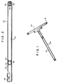
- the inflator shown as Figures 1 and 2 includes an elongated high pressure gas cylinder 50 dimensioned to serve as a structural element in a vehicle.
- a preferred intended use is as a steering column in place of present day solid columns.
- a conventional steering wheel 10 consists of a rim 12 or hub and spokes which define a well in which a shell 20 containing a folded air bag is adapted to be disposed.
- Cylinder 50 is preferably cylindrical, but it could be polygonal or oval in cross section. Cylinder 50 has a length to diameter ratio of at least 10 and preferably at least 12.5. One cylinder installed as a steering column was made of a low carbon steel and had a length of 35.6 cm (fourteen inches) and a diameter of 2.54 cm (one inch). Cylinder 50 has the usual filling opening for charging it with gas under pressure (not shown) and means to close the filling opening. Positioned at one end of chamber 50, are a pyrotechnic charge 58 and igniter 52.
- Diffuser chamber 44 is closed at its entry end by diaphragm 42 and has a screen 46 at its discharge end.
- Coarse screen 46 or a perforated metal sheet is included inside the diffuser to prevent hot particles from entering the air bag cushion. Further filtering of the hot particles is accomplished by a filter assembly (not shown) which may be in the steering column or in the steering wheel 12. A suitable interface 48 is provided for connection between the cylinder 50 and a steering wheel 12.
- the pyrotechnic portion of the inflation system is shown in greater detail in Figure 4. As seen in the Figure, it consists of a metal can 51 formed by an extension of cylinder 50. An initiator assembly 52 is mounted at one end of can 51. Electrical contact pins 53 extend out of the initiator 52 and are connected to a source of electricity (not shown) which fires the initiator when a crash occurs.
- An auto ignition charge 56 and a pyrotechnic charge 58 are enclosed in a cup shaped metal cup 60.
- the bottom closed end of cup 60 is recessed to receive initiator 52.
- the top open end of cup 60 is closed by a cap 62 which is crimped to the walls of cup 60.
- a diaphragm 54 is welded the walls of cylinder 50 to close the pyrotechnic assembly. Between the diaphragm 54 and cover 62 are a plug 66, seated in a chamfered hole 64 and a nozzle plate 68.
- Cap 62 includes an offset portion which receives a wafer 56 of auto ignition material.
- the hybrid inflator functions as follows: In response to a signal indicative of a vehicle crash, a control signal is communicated to the initiator 52 which is activated. Upon activation, the initiator fires, igniting the pyrotechnic charge 58. As pressure within the cup shaped pyrotechnic combustion chamber 60 (igniter chamber) rises until it exceeds the gas storage chamber pressure, the plug 66 is unseated. Subsequently the thin diaphragm 54 ruptures when the combustion pressure exceeds the gas storage pressure and the strength of the thin metal disk. Hot gas and hot particles from the burning pyrotechnic heat the stored gas, causing a rapid pressure rise in the storage chamber 30.
- This orifice plate 40 consists of a thin metal ring or disk with an accurately sized hole in the middle. This orifice throttles the flow of gas from the storage chamber and provides the proper fill rate into the air bag.
- the elongated tubular inflator may be substituted for some other structural element such as a beam in a door panel or a frame member for a seat back e.g. as shown in Figure 3, where it may function to protect from side impacts.
- the inflator 10 need not replace a structural element but may instead be installed in the same manner as prior art inflators, as an accessory mounted on the dashboard, steering wheel, car door, seat back, or other location on a vehicle.
- the elongated inflation and storage gas cylinder it is also possible to dimension the elongated inflation and storage gas cylinder so that it fits snugly into a tubular structural member such as a strut in a seat back or a door panel, which it then reinforces.
- the inflator 10 is provided with appropriate extensions at one end to receive the pyrotechnic assembly and at the other end to connect it to the air bag to be inflated.
Description
Claims (5)
- A hybrid inflation system for inflating airbags, comprising an elongated hollow cylinder (50) having an inner wall within which are disposed the following components:a first diaphragm (54) welded to the inner wall of the cylinder at a position spaced from one end of said cylinder to form a cup-shaped cavity at said end of the cylinder;a pyrotechnic charge (58) and an igniter (52) positioned in said cavity;a second diaphragm (42) secured to the inner wall of the cylinder near its other end;a screen (46) at the other end of the cylinder, defining a diffuser chamber (44) within the cylinder; anda storage chamber (30) within the cylinder, comprising the volume between said diaphragms (42, 54), for storing a gas under pressure.
- An inflation system according to claim 1 wherein the tubular structure (50) has a length to diameter ratio greater than 10:1.
- An inflation system according to claim 1 or claim 2, installed as a structural element in a vehicle.
- A steering column (10) for a vehicle comprising an inflator according to claim 1 or claim 2.
- An inflation system according to claim 1 or claim 2 installed within a hollow steering column (10) in a vehicle.
Applications Claiming Priority (2)
| Application Number | Priority Date | Filing Date | Title |
|---|---|---|---|
| US08/255,147 US5482315A (en) | 1994-06-07 | 1994-06-07 | Large L/D ratio tubular hybrid gas generator for the inflation of air bags |
| US255147 | 1999-02-22 |
Publications (2)
| Publication Number | Publication Date |
|---|---|
| EP0686530A1 EP0686530A1 (en) | 1995-12-13 |
| EP0686530B1 true EP0686530B1 (en) | 1998-12-23 |
Family
ID=22967042
Family Applications (1)
| Application Number | Title | Priority Date | Filing Date |
|---|---|---|---|
| EP95303786A Expired - Lifetime EP0686530B1 (en) | 1994-06-07 | 1995-06-02 | Large L/D ratio tubular hybrid gas generator for the inflation of air bags |
Country Status (4)
| Country | Link |
|---|---|
| US (1) | US5482315A (en) |
| EP (1) | EP0686530B1 (en) |
| JP (1) | JP3018669U (en) |
| DE (1) | DE69506785T2 (en) |
Families Citing this family (31)
| Publication number | Priority date | Publication date | Assignee | Title |
|---|---|---|---|---|
| US5588670A (en) * | 1995-07-20 | 1996-12-31 | Morton International, Inc. | Seat structure pressure vessel for airbag installation |
| DE29516621U1 (en) * | 1995-10-20 | 1996-01-25 | Trw Repa Gmbh | Assembly from a steering wheel, a steering shaft and a gas generator |
| US7744122B2 (en) * | 1995-12-12 | 2010-06-29 | Automotive Technologies International, Inc. | Driver side aspirated airbags |
| US5605349A (en) * | 1995-12-21 | 1997-02-25 | Kaiser Aluminum & Chemical Corporation | Integrated canister for an airbag inflator |
| DE19548266A1 (en) * | 1995-12-22 | 1997-06-26 | Temic Bayern Chem Airbag Gmbh | Gas generator for an airbag system |
| DE19613095A1 (en) * | 1996-04-01 | 1997-10-02 | Happich Gmbh Gebr | Vehicle airbag over door |
| DE19629339C2 (en) * | 1996-07-20 | 1998-07-09 | Mst Automotive Gmbh | Device for inflating an airbag housed in a steering wheel |
| DE19631739C2 (en) * | 1996-08-06 | 2000-03-09 | Fkfs Forschungsinstitut Fuer K | Protection device for one person in a vehicle |
| US5829780A (en) * | 1996-10-07 | 1998-11-03 | Chrysler Corporation | Air bag and inflator assembly |
| FR2757118B1 (en) * | 1996-12-18 | 1999-01-08 | Livbag Snc | INTEGRAL TUBULAR GAS GENERATOR BY PYROTECHNIC ROUTE, TO INFLATE PROTECTION CUSHIONS |
| US5779263A (en) * | 1997-01-21 | 1998-07-14 | Alliedsignal Inc. | Integrated side impact air bag system within a seat structure |
| DE19726260A1 (en) * | 1997-06-20 | 1998-12-24 | Temic Bayern Chem Airbag Gmbh | Gas generator for a vehicle occupant restrain system |
| US6186542B1 (en) | 1997-10-14 | 2001-02-13 | Autoliv Asp, Inc. | Compact knee bolster airbag assembly |
| US6382660B1 (en) * | 2000-04-07 | 2002-05-07 | Delphi Technologies, Inc. | Air bag assembly |
| US6890001B1 (en) * | 2000-06-01 | 2005-05-10 | Autoliv Asp, Inc. | Elongated inflator device, assembly and method of use |
| DE10031750A1 (en) * | 2000-06-29 | 2002-01-10 | Welz Industrieprodukte Gmbh | Cold gas generator for an airbag system |
| US6382661B1 (en) * | 2000-11-20 | 2002-05-07 | Trw Vehicle Safety Systems Inc. | Vehicle steering wheel having inflatable devices |
| US6588796B2 (en) * | 2001-03-08 | 2003-07-08 | Delphi Technologies, Inc. | High pressure air bag inflation system |
| DE10333173B4 (en) * | 2003-07-22 | 2007-07-12 | Takata-Petri (Sachsen) Gmbh | inflator |
| US7192055B2 (en) * | 2003-11-13 | 2007-03-20 | Automotive Systems Laboratory, Inc. | Pyrotechnic linear inflator |
| US7243946B2 (en) * | 2003-11-18 | 2007-07-17 | Automotive Systems Laboratory, Inc. | Peroxide linear inflator |
| US20050200103A1 (en) * | 2004-02-27 | 2005-09-15 | Burns Sean P. | Pyrotechnic linear inflator with structural enhancement |
| US7789018B2 (en) * | 2004-04-02 | 2010-09-07 | Automotive Systems Laboratory, Inc. | Gas generator assembly |
| US7293798B2 (en) * | 2004-04-05 | 2007-11-13 | Automotive Systems Laboratory, Inc. | Pyrotechnic linear inflator |
| WO2006015089A2 (en) * | 2004-07-27 | 2006-02-09 | Automotive Systems Laboratory, Inc. | Vehicle component with integral inflator |
| US8622419B2 (en) * | 2004-07-27 | 2014-01-07 | Automotive Systems Laboratory, Inc. | Vehicle component with integral inflator |
| US7380820B2 (en) * | 2005-06-23 | 2008-06-03 | Trw Vehicle Safety Systems Inc. | Heated gas inflator |
| US7637533B2 (en) * | 2006-01-25 | 2009-12-29 | Daicel Chemical Industries, Ltd. | Gas generator |
| DE102012006504A1 (en) * | 2012-03-29 | 2013-10-02 | GM Global Technology Operations LLC (n. d. Gesetzen des Staates Delaware) | Gas generator i.e. pipe gas generator, for e.g. vacuum-folded airbag arrangement, for protecting driver during crash, has pressure chamber portion which changes in direction within profile of pressure chamber |
| JP6251662B2 (en) * | 2014-09-29 | 2017-12-20 | 株式会社ダイセル | Gas generator |
| JP6867897B2 (en) * | 2017-06-29 | 2021-05-12 | 株式会社ダイセル | Sealing structure |
Family Cites Families (23)
| Publication number | Priority date | Publication date | Assignee | Title |
|---|---|---|---|---|
| US3506281A (en) * | 1967-10-06 | 1970-04-14 | Eaton Yale & Towne | Vehicle safety apparatus |
| US3606377A (en) | 1968-11-04 | 1971-09-20 | Eaton Yale & Towne | Vehicle crash restraint system |
| US3632135A (en) * | 1969-09-15 | 1972-01-04 | Eaton Yale & Towne | Reservoir in the steering column |
| FR2098804A5 (en) * | 1970-07-28 | 1972-03-10 | Peugeot & Renault | |
| US3680884A (en) * | 1970-10-21 | 1972-08-01 | Allied Chem | Vehicle safety assembly |
| DE2052357A1 (en) * | 1970-10-24 | 1972-04-27 | Lenkradwerk Gustav Petri Ag, 8750 Aschaffenburg | Steering wheel with built-in air cushion |
| GB1324401A (en) * | 1970-12-29 | 1973-07-25 | Kidde & Co Walter | Vehicle safety device |
| US3708194A (en) | 1971-05-24 | 1973-01-02 | A Amit | Vehicle safety apparatus |
| IT1017358B (en) * | 1973-07-26 | 1977-07-20 | Eaton Corp | COMPLEX FOR RETAINING THE OCCUPANCY OF A VEHICLE |
| DE2524770A1 (en) * | 1975-06-04 | 1976-12-16 | Volkswagenwerk Ag | SECURITY DEVICE |
| US4275901A (en) * | 1978-07-21 | 1981-06-30 | Honda Giken Kogyo Kabushiki Kaisha | Inflatable safety bag system for vehicles |
| IT8004893V0 (en) | 1980-07-08 | 1980-07-08 | Italvolanti Di Maestri Luciano | SAFETY DEVICE FOR MOTORCYCLE DRIVING WHEELS |
| US4796912A (en) * | 1987-11-12 | 1989-01-10 | Morton Thiokol, Inc. | Elongate gas generator for inflating vehicle inflatable restraint cushions |
| GB2227552B (en) * | 1988-11-24 | 1992-12-09 | Autoliv Dev | Improvements in or relating to a gas generator |
| US5290060A (en) | 1992-12-14 | 1994-03-01 | Morton International, Inc. | Hybrid gas generator for air bag inflatable restraint systems |
| US5066038A (en) * | 1990-07-31 | 1991-11-19 | Bendix Atlantic Inflator Company | Driver side hybrid inflator and air bag module |
| US5131680A (en) * | 1991-03-19 | 1992-07-21 | Trw Vehicle Safety Systems Inc. | Inflator assembly |
| US5190313A (en) * | 1991-08-07 | 1993-03-02 | Robert Hickling | Impact cushioning device |
| DE4209944A1 (en) * | 1992-03-27 | 1993-05-19 | Daimler Benz Ag | Side impact protection for vehicle occupant - using airbag in side door with gas generator inside reinforcing strut |
| US5242194A (en) * | 1992-10-23 | 1993-09-07 | Trw Vehicle Safety Systems Inc. | Air bag inflator |
| US5342089A (en) * | 1993-01-13 | 1994-08-30 | Ideatech, Inc. | Combined air bag device and steering column for vehicles |
| FR2702724B1 (en) * | 1993-03-18 | 1995-06-16 | Ecia Equip Composants Ind Auto | Steering column assembly provided with an airbag module, in particular for a motor vehicle. |
| US5290059A (en) * | 1993-04-28 | 1994-03-01 | Morton International, Inc. | Air bag module with a center mounted tubular inflator |
-
1994
- 1994-06-07 US US08/255,147 patent/US5482315A/en not_active Expired - Fee Related
-
1995
- 1995-05-26 JP JP1995005027U patent/JP3018669U/en not_active Expired - Lifetime
- 1995-06-02 EP EP95303786A patent/EP0686530B1/en not_active Expired - Lifetime
- 1995-06-02 DE DE69506785T patent/DE69506785T2/en not_active Expired - Fee Related
Also Published As
| Publication number | Publication date |
|---|---|
| JP3018669U (en) | 1995-11-28 |
| US5482315A (en) | 1996-01-09 |
| DE69506785D1 (en) | 1999-02-04 |
| EP0686530A1 (en) | 1995-12-13 |
| DE69506785T2 (en) | 1999-05-20 |
Similar Documents
| Publication | Publication Date | Title |
|---|---|---|
| EP0686530B1 (en) | Large L/D ratio tubular hybrid gas generator for the inflation of air bags | |
| EP1056624B1 (en) | Adaptive output inflator | |
| US5664802A (en) | Adjustable performance hybrid inflator | |
| US5324072A (en) | Side impact air bag | |
| US5058921A (en) | Linear bilateral inflator module | |
| JP3031246U (en) | Pressurized gas inflator | |
| US4131300A (en) | Inflator for automobile safety device | |
| EP1509426B1 (en) | Gas generant filter assembly, combination comprising a filter and a closure and an airbag inflator | |
| KR100517749B1 (en) | A method of filling an empty, flexible container, and a container device | |
| US6425601B1 (en) | Air bag module | |
| WO2000050273A1 (en) | Dual stage inflator | |
| US5813694A (en) | Hybrid air bag system having an improved hybrid inflator | |
| US5670738A (en) | Hybrid inflator with pop-out diffuser | |
| EP1613508B1 (en) | Belt and side impact inflator | |
| JP3082426B2 (en) | Airbag inflator | |
| EP1619087A2 (en) | Gas generator for air bag and air bag apparatus. | |
| JP3875382B2 (en) | Airbag deployment method in airbag device | |
| JP5174752B2 (en) | Gas generator for airbag | |
| JPH0640043Y2 (en) | Airbag device | |
| JPH0939709A (en) | Air bag device | |
| KR19990029267U (en) | Car airbag structure | |
| JP2003011771A (en) | Gas generator | |
| KR19990026015U (en) | Air Cushion System of Vehicle |
Legal Events
| Date | Code | Title | Description |
|---|---|---|---|
| PUAI | Public reference made under article 153(3) epc to a published international application that has entered the european phase |
Free format text: ORIGINAL CODE: 0009012 |
|
| AK | Designated contracting states |
Kind code of ref document: A1 Designated state(s): DE FR GB IT |
|
| 17P | Request for examination filed |
Effective date: 19960517 |
|
| 17Q | First examination report despatched |
Effective date: 19970609 |
|
| GRAG | Despatch of communication of intention to grant |
Free format text: ORIGINAL CODE: EPIDOS AGRA |
|
| GRAG | Despatch of communication of intention to grant |
Free format text: ORIGINAL CODE: EPIDOS AGRA |
|
| GRAH | Despatch of communication of intention to grant a patent |
Free format text: ORIGINAL CODE: EPIDOS IGRA |
|
| GRAH | Despatch of communication of intention to grant a patent |
Free format text: ORIGINAL CODE: EPIDOS IGRA |
|
| GRAA | (expected) grant |
Free format text: ORIGINAL CODE: 0009210 |
|
| RAP1 | Party data changed (applicant data changed or rights of an application transferred) |
Owner name: AUTOLIV ASP, INC. |
|
| AK | Designated contracting states |
Kind code of ref document: B1 Designated state(s): DE FR GB IT |
|
| PG25 | Lapsed in a contracting state [announced via postgrant information from national office to epo] |
Ref country code: IT Free format text: LAPSE BECAUSE OF FAILURE TO SUBMIT A TRANSLATION OF THE DESCRIPTION OR TO PAY THE FEE WITHIN THE PRESCRIBED TIME-LIMIT;WARNING: LAPSES OF ITALIAN PATENTS WITH EFFECTIVE DATE BEFORE 2007 MAY HAVE OCCURRED AT ANY TIME BEFORE 2007. THE CORRECT EFFECTIVE DATE MAY BE DIFFERENT FROM THE ONE RECORDED. Effective date: 19981223 |
|
| REF | Corresponds to: |
Ref document number: 69506785 Country of ref document: DE Date of ref document: 19990204 |
|
| ET | Fr: translation filed | ||
| PLBE | No opposition filed within time limit |
Free format text: ORIGINAL CODE: 0009261 |
|
| STAA | Information on the status of an ep patent application or granted ep patent |
Free format text: STATUS: NO OPPOSITION FILED WITHIN TIME LIMIT |
|
| 26N | No opposition filed | ||
| REG | Reference to a national code |
Ref country code: GB Ref legal event code: IF02 |
|
| PGFP | Annual fee paid to national office [announced via postgrant information from national office to epo] |
Ref country code: FR Payment date: 20060620 Year of fee payment: 12 |
|
| PGFP | Annual fee paid to national office [announced via postgrant information from national office to epo] |
Ref country code: GB Payment date: 20060626 Year of fee payment: 12 |
|
| PGFP | Annual fee paid to national office [announced via postgrant information from national office to epo] |
Ref country code: DE Payment date: 20060731 Year of fee payment: 12 |
|
| GBPC | Gb: european patent ceased through non-payment of renewal fee |
Effective date: 20070602 |
|
| REG | Reference to a national code |
Ref country code: FR Ref legal event code: ST Effective date: 20080229 |
|
| PG25 | Lapsed in a contracting state [announced via postgrant information from national office to epo] |
Ref country code: DE Free format text: LAPSE BECAUSE OF NON-PAYMENT OF DUE FEES Effective date: 20080101 |
|
| PG25 | Lapsed in a contracting state [announced via postgrant information from national office to epo] |
Ref country code: GB Free format text: LAPSE BECAUSE OF NON-PAYMENT OF DUE FEES Effective date: 20070602 |
|
| PG25 | Lapsed in a contracting state [announced via postgrant information from national office to epo] |
Ref country code: FR Free format text: LAPSE BECAUSE OF NON-PAYMENT OF DUE FEES Effective date: 20070702 |