EP0686441B1 - Structure for and method of joining metal plate materials - Google Patents
Structure for and method of joining metal plate materials Download PDFInfo
- Publication number
- EP0686441B1 EP0686441B1 EP94929015A EP94929015A EP0686441B1 EP 0686441 B1 EP0686441 B1 EP 0686441B1 EP 94929015 A EP94929015 A EP 94929015A EP 94929015 A EP94929015 A EP 94929015A EP 0686441 B1 EP0686441 B1 EP 0686441B1
- Authority
- EP
- European Patent Office
- Prior art keywords
- metal plate
- projections
- edge
- metal plates
- joining
- Prior art date
- Legal status (The legal status is an assumption and is not a legal conclusion. Google has not performed a legal analysis and makes no representation as to the accuracy of the status listed.)
- Expired - Lifetime
Links
Images



Classifications
-
- B—PERFORMING OPERATIONS; TRANSPORTING
- B21—MECHANICAL METAL-WORKING WITHOUT ESSENTIALLY REMOVING MATERIAL; PUNCHING METAL
- B21D—WORKING OR PROCESSING OF SHEET METAL OR METAL TUBES, RODS OR PROFILES WITHOUT ESSENTIALLY REMOVING MATERIAL; PUNCHING METAL
- B21D39/00—Application of procedures in order to connect objects or parts, e.g. coating with sheet metal otherwise than by plating; Tube expanders
- B21D39/02—Application of procedures in order to connect objects or parts, e.g. coating with sheet metal otherwise than by plating; Tube expanders of sheet metal by folding, e.g. connecting edges of a sheet to form a cylinder
- B21D39/026—Reinforcing the connection by locally deforming
-
- B—PERFORMING OPERATIONS; TRANSPORTING
- B21—MECHANICAL METAL-WORKING WITHOUT ESSENTIALLY REMOVING MATERIAL; PUNCHING METAL
- B21D—WORKING OR PROCESSING OF SHEET METAL OR METAL TUBES, RODS OR PROFILES WITHOUT ESSENTIALLY REMOVING MATERIAL; PUNCHING METAL
- B21D39/00—Application of procedures in order to connect objects or parts, e.g. coating with sheet metal otherwise than by plating; Tube expanders
- B21D39/02—Application of procedures in order to connect objects or parts, e.g. coating with sheet metal otherwise than by plating; Tube expanders of sheet metal by folding, e.g. connecting edges of a sheet to form a cylinder
-
- Y—GENERAL TAGGING OF NEW TECHNOLOGICAL DEVELOPMENTS; GENERAL TAGGING OF CROSS-SECTIONAL TECHNOLOGIES SPANNING OVER SEVERAL SECTIONS OF THE IPC; TECHNICAL SUBJECTS COVERED BY FORMER USPC CROSS-REFERENCE ART COLLECTIONS [XRACs] AND DIGESTS
- Y10—TECHNICAL SUBJECTS COVERED BY FORMER USPC
- Y10T—TECHNICAL SUBJECTS COVERED BY FORMER US CLASSIFICATION
- Y10T29/00—Metal working
- Y10T29/49—Method of mechanical manufacture
- Y10T29/49826—Assembling or joining
- Y10T29/49833—Punching, piercing or reaming part by surface of second part
-
- Y—GENERAL TAGGING OF NEW TECHNOLOGICAL DEVELOPMENTS; GENERAL TAGGING OF CROSS-SECTIONAL TECHNOLOGIES SPANNING OVER SEVERAL SECTIONS OF THE IPC; TECHNICAL SUBJECTS COVERED BY FORMER USPC CROSS-REFERENCE ART COLLECTIONS [XRACs] AND DIGESTS
- Y10—TECHNICAL SUBJECTS COVERED BY FORMER USPC
- Y10T—TECHNICAL SUBJECTS COVERED BY FORMER US CLASSIFICATION
- Y10T29/00—Metal working
- Y10T29/49—Method of mechanical manufacture
- Y10T29/49826—Assembling or joining
- Y10T29/49885—Assembling or joining with coating before or during assembling
-
- Y—GENERAL TAGGING OF NEW TECHNOLOGICAL DEVELOPMENTS; GENERAL TAGGING OF CROSS-SECTIONAL TECHNOLOGIES SPANNING OVER SEVERAL SECTIONS OF THE IPC; TECHNICAL SUBJECTS COVERED BY FORMER USPC CROSS-REFERENCE ART COLLECTIONS [XRACs] AND DIGESTS
- Y10—TECHNICAL SUBJECTS COVERED BY FORMER USPC
- Y10T—TECHNICAL SUBJECTS COVERED BY FORMER US CLASSIFICATION
- Y10T428/00—Stock material or miscellaneous articles
- Y10T428/12—All metal or with adjacent metals
- Y10T428/12229—Intermediate article [e.g., blank, etc.]
- Y10T428/12264—Intermediate article [e.g., blank, etc.] having outward flange, gripping means or interlocking feature
-
- Y—GENERAL TAGGING OF NEW TECHNOLOGICAL DEVELOPMENTS; GENERAL TAGGING OF CROSS-SECTIONAL TECHNOLOGIES SPANNING OVER SEVERAL SECTIONS OF THE IPC; TECHNICAL SUBJECTS COVERED BY FORMER USPC CROSS-REFERENCE ART COLLECTIONS [XRACs] AND DIGESTS
- Y10—TECHNICAL SUBJECTS COVERED BY FORMER USPC
- Y10T—TECHNICAL SUBJECTS COVERED BY FORMER US CLASSIFICATION
- Y10T428/00—Stock material or miscellaneous articles
- Y10T428/12—All metal or with adjacent metals
- Y10T428/12347—Plural layers discontinuously bonded [e.g., spot-weld, mechanical fastener, etc.]
-
- Y—GENERAL TAGGING OF NEW TECHNOLOGICAL DEVELOPMENTS; GENERAL TAGGING OF CROSS-SECTIONAL TECHNOLOGIES SPANNING OVER SEVERAL SECTIONS OF THE IPC; TECHNICAL SUBJECTS COVERED BY FORMER USPC CROSS-REFERENCE ART COLLECTIONS [XRACs] AND DIGESTS
- Y10—TECHNICAL SUBJECTS COVERED BY FORMER USPC
- Y10T—TECHNICAL SUBJECTS COVERED BY FORMER US CLASSIFICATION
- Y10T428/00—Stock material or miscellaneous articles
- Y10T428/12—All metal or with adjacent metals
- Y10T428/12354—Nonplanar, uniform-thickness material having symmetrical channel shape or reverse fold [e.g., making acute angle, etc.]
-
- Y—GENERAL TAGGING OF NEW TECHNOLOGICAL DEVELOPMENTS; GENERAL TAGGING OF CROSS-SECTIONAL TECHNOLOGIES SPANNING OVER SEVERAL SECTIONS OF THE IPC; TECHNICAL SUBJECTS COVERED BY FORMER USPC CROSS-REFERENCE ART COLLECTIONS [XRACs] AND DIGESTS
- Y10—TECHNICAL SUBJECTS COVERED BY FORMER USPC
- Y10T—TECHNICAL SUBJECTS COVERED BY FORMER US CLASSIFICATION
- Y10T428/00—Stock material or miscellaneous articles
- Y10T428/12—All metal or with adjacent metals
- Y10T428/12493—Composite; i.e., plural, adjacent, spatially distinct metal components [e.g., layers, joint, etc.]
- Y10T428/12535—Composite; i.e., plural, adjacent, spatially distinct metal components [e.g., layers, joint, etc.] with additional, spatially distinct nonmetal component
Definitions
- the present invention relates to a method of joining metal plates and to a joined structure of metal plates according to the preambles of claims 1 and 3 respectively.
- this invention can be utilized for joining a front panel having opening which is a structural member of a cooking apparatus with a cylindrical shell plate serving as inner case, joining in sheet metal structures of an automobile, etc.
- a method of joining edges of inner and outer panels is disclosed in US-A-5237,734, in which raised beads are formed along the edge of the inner panel, placing the inner panel inside the outer panel on a platen with the beads facing away from the outer panel and hemming the edge of the outer panel over the inner panel using punch means.
- the punch means having a plurality of slots corresponding to the raised beads.
- Cooking apparatus (1) such as a microwave oven, oven, etc. is composed of main body (2) and door (3) as shown in Fig. 2 (A).
- the main body (2) is provided with an inner case (4) to make effective use of heat and prevent leakage of electric waves.
- the inner case (4) is constructed with front panel (5), shell (6) and rear panel (8) as shown in Fig. 2 (B).
- the shell (6) has a cylindrical structure and is composed of top plate (9) and shell plate (10) with U-shaped section.
- the front panel (5) is provided with an opening (7) to enable putting in and taking out of object material for cooking.
- the shell (6) and the front panel (5) are joined into an integral structure by wound caulking popularly known as curling at the front edge of the shell plate (10), the front edge of the top plate (9) and the periphery (7A) of the opening (7) (see JP-U-59-41444).
- a folded part (7B) is formed on the entire circumference in preparation for curling. Moreover, at the front edges of the top and shell plates (9,10) constituting the shell (6), folded parts (9B, 10B) are formed, respectively, as joining means corresponding to the folded part (7B) on the front panel (5) side.
- the joining of the front panel (5) and the front edge of the shell (6) into an integral body is performed by putting the folded part (7B) on the front panel (5) side and the folded parts (9B, 10B) on the shell (6) side one upon the other and applying a load P in the direction X, as shown in Fig. 3 (A).
- the respective folded parts (7B, 9B, 10B) form a solid joined structure not producing any deviation in their mutual joining positions even when the circumference of opening (7A) of the front panel (5) is pulled in the direction Y or when the front edge (9B) of the top plate (9) or the front edge (10B) of the shell plate (10) is pulled in the direction Y', by having their respective tip parts held inside the folded part of their counterparts.
- a tensile load in the direction opposite to above acts, i.e., if the circumference of opening (7A) of the front panel (5) is pulled in the direction Y' or the front edge (9B or 10B) of the top plate (9) or the shell plate (10) is pulled in the direction Y, the joined structure loses its joining strength, producing a mutual displacement among the front panel (5), the top plate (9) and the shell plate (10) because no fastening means is provided in the direction of movement of the respective folded parts (7B, 9B, 10B).
- the joining system by curling shown in Fig. 3 (A) could not provide any joined structure capable of demonstrating a solid joining strength In all directions.
- JP-U-58-41411, JP-A-59-119118, on which the preambles of claims 1 and 3 are based, JP-Y-1-38418, etc. form, in a heating chamber of a microwave oven constructed by caulking the inner case (4) and the front panel (5), in which, as shown in Fig. 3(B), a plural number of projections (11) are formed at prescribed intervals on one of the inner case (4) and the front panel (5), e.g. on the front panel (5) and a plural number of holes (12) are formed at the same intervals as those of the projections (11) on the other, e.g. in the top plate (9) and the shell plate (10), so that the projections (11) are received in the holes (12) as a result of curling, thereby preventing separation of the inner case (4) from the front panel (5).
- cut and raised portion, or tongues (11A) are provided at prescribed interval in the circumference of opening (7A) of the front panel (5) as substitute member for a plural number of small projections (11).
- the tongues (11A) advance in the holes (12) at the time of curling, and thus the inner case (4) and the front panel (5) are joined into an integral structure.
- the present invention provides a method of joining metal plates together comprising the steps of placing a first metal plate having an edge folded at an acute angle and a second metal plate having an edge folded at an acute angle one upon the other in such a way that said edges face in opposite directions and bending said edges over each other to integrally unite said first and second metal plates, the first metal plate being provided with projections at prescribed intervals along a longitudinal direction of said edge, characterised in that the second metal plate is provided with an insulating film on a surface thereof, and the method further comprises applying a load to said first and second metal plates to bend the edges one over the other such that said projections are forcibly pushed into the surface of the second metal plate having said insulating film such that the insulating film is broken with a tip of said projections.
- Projections may be provided at the edge of one of the metal plates only, or alternatively, the respective edge of the both metal plates have such projection with locations thereof displaced.
- the metal plate not having projections at its edge may preferably by means of a jig having recesses at the positions corresponding to the projections.
- the present invention provides a structure of metal plates comprising first metal plate having an edge and second metal plate having a second edge, joined together by placing the metal plates one upon the other so that said edges are bent at acute angles and oppose each other, and applying a load onto the opposing edges to integrally unite said metal plates, wherein projections are formed on a surface of an edge of the first metal plate at prescribed intervals along a longitudinal direction, characterised in that the second metal plate has an insulating film on a surface thereof which is partially broken by said projections.
- the insulating film formed on a surface of the other metal plate is broken at the tip of the projections when the projections are forcibly pushed in.
- the present invention provides an integral structure in which the film on the other metal plate is partially broken by the projections.
- the projections provided at the edge of one metal plate are forcibly pushed into the edge of the other metal plate by plastically deforming the edge of the latter.
- the projections provided at the edge of one metal plate and the edge portion of the other metal plate plastically deformed along those projections engage well with each other and constitute a solid positioning means.
- the insulating film provided on the surface of the mating metal plate is broken when the projections are forcibly pushed in and, as a result, a joined structure securing electric continuity between metal plates can be obtained.
- Fig. 1 (A) shows the cross-sectional shape of the metal plates (5, 9, 10) before joining
- Fig. 1 (B) shows the cross-sectional shape of a first metal plate (5) and a second metal plate (9, 10) joined into an integral structure.
- the first metal plate (5) has an edge (21) for joining folded at an acute angle, and projections (11) are provided at prescribed intervals in the longitudinal direction (direction perpendicular to the face of the drawing sheet) on this edge (21).
- the projections (11) are formed in advance at the edge (21) of the first metal plate (5) prior to the joining process.
- the second metal plate (9) has an edge (22) for joining folded at an acute angle in the direction opposite to the edge (21) of the first metal plate (5).
- This edge (22) has the shape of a flat plate.
- the first metal plate (5) and the second metal plate (9) are placed on a lower die (15) in the state where the edge (21) of the first metal plate (5) having projections (11) and the flat edge (22) of the second metal plate (9) are placed one upon the other in opposite directions (see Fig. 1 (B)). At this time, positioning is made in such a way that the position of the projections (11) of the first metal plate (5) agrees with the position of the holes (16) provided in the lower die (15).
- the upper die (14) is lowered to apply a load P to the metal plates (5, 9) placed one upon the other from above the first metal plate (5).
- the edges (21, 22) are pressed and bent and at the same time the projections (11) are forcibly advanced into the edge (22) of the counterpart, causing the edge (22) to be plastically deformed according to the shape of the projections (11).
- the hole (16) in the lower die (15) receives the portion swollen downward (13) as a result of plastic deformation of the edge (22).
- the first and second metal plates (5, 9) joined together present a form as shown in Fig. 1 (B). Because the projections (11) of the edge (21) on one side and the plastically deformed portions (13) of the edge 22 on the other side are engaged closely with each other, any relative displacement of the first and the second metal plates is prevented, providing a joined structure having a joining strength sufficiently large from the practical viewpoint.
- Fig. 4 (A) shows an embodiment in which the present invention is applied to the joining of the inner case of a cooking apparatus.
- the inner case (4) of a cooking apparatus is constructed with a shell plate (10) with U-shaped section, a front panel (5) joined to the front edge of the shell plate (10), a rear panel (8) joined to the rear edge of the shell plate (10) and a top plate (9) joined to the opening in the upper face of the shell plate (10).
- the aforementioned joined structure indicated in Fig. 1 is adopted for the joining of the shell plate (10) and the front panel (5) and the joining of the top plate (9) and the front panel (5), while the joined structure as illustrated in Fig.
- FIG. 4 (B) is adopted for the joining of the shell plate (10) and the rear panel (8) and also for the joining of the shell plate (10) and the top plate (9).
- the method and apparatus for obtaining the joined structure indicated in Fig. 4 are disclosed by JP-B-60-18259, JP-B-61-18889, JP-A-62-244533. etc., for example, though they are well known in the art of joining of metal plates.
- the present invention has been explained based on a concrete embodiment in which it is utilized in the assembling process of the inner case of a cooking apparatus, the present invention must not be interpreted restrictively with the example explained above, but can also be utilized for technical fields other than above. For example, it can also be utilized as means for joining and integrating metal plates having a coating layer and accordingly unfit for welding.
- the projections (11) are forcibly advanced into the mating metal plate and this causes breakage or separation of the insulating film and, as a result, secure electric continuity between the metal plates (5, 9) in the joined structure is thus obtained.
- the projections (11) may take the form of burring holes as illustrated in Fig. 5, where it becomes possible to obtain continuity by breaking the paint film of the mating metal plate (9) with the knife edge at the tip of the burring holes.
- burring holes exposing a knife edge are believed to be most effective for breaking the film of the mating metal plate.
- Burring holes which are generally intended for tapping, are worked by using burring tools (23, 24) after perforation in metal plates.
- burring tools 23, 24
- a tool (25) of conical shape or in the shape of pyramid as shown in Fig. 8 in place of an ordinary burring tool (23), it is possible to form projections exposing edges with broken tip.
- the projections provided at the edge of one of the metal plates are forcibly advanced into the edge of the other metal plate by plastically deforming the latter edge and, as a result, those projections and the portion at edge of the other metal plate plastically deformed in the shape of the projections are engaged well with each other to constitute a solid positioning or interlocking means.
- any relative displacement can be securely prevented in a joined structure realized by joining a first and a second metal plates this way.
- the joined structure according to the invention secures electric continuity between the joined metal plates to prevent leakage of electric waves as in microwave ovens, etc.
Landscapes
- Engineering & Computer Science (AREA)
- Mechanical Engineering (AREA)
- Electric Ovens (AREA)
- Connection Of Plates (AREA)
- Cookers (AREA)
Abstract
Description
- The present invention relates to a method of joining metal plates and to a joined structure of metal plates according to the preambles of
claims 1 and 3 respectively. To explain it with examples, this invention can be utilized for joining a front panel having opening which is a structural member of a cooking apparatus with a cylindrical shell plate serving as inner case, joining in sheet metal structures of an automobile, etc. - A method of joining edges of inner and outer panels is disclosed in US-A-5237,734, in which raised beads are formed along the edge of the inner panel, placing the inner panel inside the outer panel on a platen with the beads facing away from the outer panel and hemming the edge of the outer panel over the inner panel using punch means. The punch means having a plurality of slots corresponding to the raised beads.
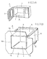
- Cooking apparatus (1) such as a microwave oven, oven, etc. is composed of main body (2) and door (3) as shown in Fig. 2 (A). The main body (2) is provided with an inner case (4) to make effective use of heat and prevent leakage of electric waves.
- The inner case (4) is constructed with front panel (5), shell (6) and rear panel (8) as shown in Fig. 2 (B). The shell (6) has a cylindrical structure and is composed of top plate (9) and shell plate (10) with U-shaped section. The front panel (5) is provided with an opening (7) to enable putting in and taking out of object material for cooking.
- The shell (6) and the front panel (5) are joined into an integral structure by wound caulking popularly known as curling at the front edge of the shell plate (10), the front edge of the top plate (9) and the periphery (7A) of the opening (7) (see JP-U-59-41444).
- In the opening (7) of the front panel (5), a folded part (7B) is formed on the entire circumference in preparation for curling. Moreover, at the front edges of the top and shell plates (9,10) constituting the shell (6), folded parts (9B, 10B) are formed, respectively, as joining means corresponding to the folded part (7B) on the front panel (5) side.
- The joining of the front panel (5) and the front edge of the shell (6) into an integral body is performed by putting the folded part (7B) on the front panel (5) side and the folded parts (9B, 10B) on the shell (6) side one upon the other and applying a load P in the direction X, as shown in Fig. 3 (A).
- As it is understood from Fig. 3 (A), the respective folded parts (7B, 9B, 10B) form a solid joined structure not producing any deviation in their mutual joining positions even when the circumference of opening (7A) of the front panel (5) is pulled in the direction Y or when the front edge (9B) of the top plate (9) or the front edge (10B) of the shell plate (10) is pulled in the direction Y', by having their respective tip parts held inside the folded part of their counterparts.
- However, when, in the joined structure as shown in Fig. 3 (A), a tensile load in the direction opposite to above acts, i.e., if the circumference of opening (7A) of the front panel (5) is pulled in the direction Y' or the front edge (9B or 10B) of the top plate (9) or the shell plate (10) is pulled in the direction Y, the joined structure loses its joining strength, producing a mutual displacement among the front panel (5), the top plate (9) and the shell plate (10) because no fastening means is provided in the direction of movement of the respective folded parts (7B, 9B, 10B).
- Therefore, the joining system by curling shown in Fig. 3 (A) could not provide any joined structure capable of demonstrating a solid joining strength In all directions.
- To solve such problem, in the prior art according to JP-U-58-41411, JP-A-59-119118, on which the preambles of
claims 1 and 3 are based, JP-Y-1-38418, etc. form, in a heating chamber of a microwave oven constructed by caulking the inner case (4) and the front panel (5), in which, as shown in Fig. 3(B), a plural number of projections (11) are formed at prescribed intervals on one of the inner case (4) and the front panel (5), e.g. on the front panel (5) and a plural number of holes (12) are formed at the same intervals as those of the projections (11) on the other, e.g. in the top plate (9) and the shell plate (10), so that the projections (11) are received in the holes (12) as a result of curling, thereby preventing separation of the inner case (4) from the front panel (5). - In the prior art as shown in Fig. 3 (C), cut and raised portion, or tongues (11A) are provided at prescribed interval in the circumference of opening (7A) of the front panel (5) as substitute member for a plural number of small projections (11). The tongues (11A) advance in the holes (12) at the time of curling, and thus the inner case (4) and the front panel (5) are joined into an integral structure.
- In the prior art described above, it is necessary for the every projection (11) or tongue (11A) advances in the hole (12), and any deviation at a single point in the positional relation between the projections (11) or tongues (11A) and the holes (12) makes curling impossible. For that reason, it is indispensable to accurately position all the projections (11) or tongues (11A) with respect to the holes (12).
- However, this positioning, which is a very troublesome work, not only put an obstacle to labor saving but also presented a great restriction to the maintenance of the working accuracy.
- Moreover, in the prior art described above, it was necessary to make the size of the projections (11) or tongues (11A) somewhat smaller than that of the holes (12) to facilitate advancement of the projections (11) or tongues (11A) into the holes (12). As a result, there was a problem, after the completion of curling, of a gap produced between the projections (11) or tongues (11A) and the holes (12) or, in the case of a weak tightening load P, a problem of displacement of projections (11) or tongues (11A), thereby causing a play between the inner case (4) and the front panel (5).
- The present invention provides a method of joining metal plates together comprising the steps of placing a first metal plate having an edge folded at an acute angle and a second metal plate having an edge folded at an acute angle one upon the other in such a way that said edges face in opposite directions and bending said edges over each other to integrally unite said first and second metal plates, the first metal plate being provided with projections at prescribed intervals along a longitudinal direction of said edge, characterised in that the second metal plate is provided with an insulating film on a surface thereof, and the method further comprises applying a load to said first and second metal plates to bend the edges one over the other such that said projections are forcibly pushed into the surface of the second metal plate having said insulating film such that the insulating film is broken with a tip of said projections.
- Projections may be provided at the edge of one of the metal plates only, or alternatively, the respective edge of the both metal plates have such projection with locations thereof displaced.
- When the edges are subjected to bending load, the metal plate not having projections at its edge may preferably by means of a jig having recesses at the positions corresponding to the projections.
- Moreover, the present invention provides a structure of metal plates comprising first metal plate having an edge and second metal plate having a second edge, joined together by placing the metal plates one upon the other so that said edges are bent at acute angles and oppose each other, and applying a load onto the opposing edges to integrally unite said metal plates, wherein projections are formed on a surface of an edge of the first metal plate at prescribed intervals along a longitudinal direction, characterised in that the second metal plate has an insulating film on a surface thereof which is partially broken by said projections.
- The insulating film formed on a surface of the other metal plate, is broken at the tip of the projections when the projections are forcibly pushed in. Thus, the present invention provides an integral structure in which the film on the other metal plate is partially broken by the projections.
- The projections provided at the edge of one metal plate are forcibly pushed into the edge of the other metal plate by plastically deforming the edge of the latter. As a result, the projections provided at the edge of one metal plate and the edge portion of the other metal plate plastically deformed along those projections engage well with each other and constitute a solid positioning means.
- Consequently, in a joined structure composed of the first and second metal plates joined this way, any displacement can be prevented securely. And yet, because the edge part not having any projections is flat and that the projections are pushed in there, the joining work is easy without requiring any troublesome positioning.
- By supporting the metal plate not having any projections at its edge with a jig having recessed formed at positions corresponding to the projections, the plastic deformation of the edge in which the projections are pushed in can be made smoothly.
- Moreover, the insulating film provided on the surface of the mating metal plate is broken when the projections are forcibly pushed in and, as a result, a joined structure securing electric continuity between metal plates can be obtained.
-
- Fig. 1(A) is a sectional view showing the shape of the respective metal plates before joining;
- Fig. 1 (B) is a sectional view of the respective metal plates after joining;
- Fig. 2 (A) is a perspective view explaining the general structure of a microwave oven or an oven;
- Fig. 2 (B) is a perspective view explaining the state of joining between the front panel and the shell;
- Fig. 3 (A), Fig. 3 (B) and Fig. 3 (C) are sectional views showing prior art;
- Fig. 4 (A) is a perspective view of the inner case of a cooking apparatus showing an embodiment in which the invention can be applied to the joining of the inner case of a cooking apparatus;
- Fig. 4 (B) is a partial sectional view;
- Fig. 5 (a) and Fig. 5 (b) are sectional views showing an embodiment in which the projections take the form of burring holes;
- Fig. 6 (a) is a plan view exemplifying a projection in the form of a quadrangular pyramid;
- Fig. 6 (b) is a plan view exemplifying a projection in the form of a triangular pyramid;
- Fig. 7 (a) is a sectional view showing the shape of metal plates before burring;
- Fig. 7 (b) is a sectional view showing the shape of metal plates after burring; and
- Fig. 8 is a sectional view showing the method of formation of a projection broken at the tip.
-
- An embodiment of the present invention will now be described with reference to Fig. 1.
- In the paragraphs that follow, explanation will be given by taking for example a case where the present invention is applied to the joining of the inner case of a cooking apparatus described previously in relation to Fig. 2 and Fig. 3, and those elements equivalent to the elements as in the prior art stated earlier will be designated with the same reference numerals while explanation will be omitted on any matters overlapping with the prior art.
- Fig. 1 (A) shows the cross-sectional shape of the metal plates (5, 9, 10) before joining, and Fig. 1 (B) shows the cross-sectional shape of a first metal plate (5) and a second metal plate (9, 10) joined into an integral structure.
- As the second metal plate, there is no difference between the metal plate (top plate) (9) and the metal plate (shell plate) (10) as far as the joined part is concerned and, therefore, reference will be made to the metal plate (9) only hereafter.
- As shown in Fig. 1 (A), the first metal plate (5) has an edge (21) for joining folded at an acute angle, and projections (11) are provided at prescribed intervals in the longitudinal direction (direction perpendicular to the face of the drawing sheet) on this edge (21). The projections (11) are formed in advance at the edge (21) of the first metal plate (5) prior to the joining process. The second metal plate (9) has an edge (22) for joining folded at an acute angle in the direction opposite to the edge (21) of the first metal plate (5). This edge (22) has the shape of a flat plate.
- In the process of joining, the first metal plate (5) and the second metal plate (9) are placed on a lower die (15) in the state where the edge (21) of the first metal plate (5) having projections (11) and the flat edge (22) of the second metal plate (9) are placed one upon the other in opposite directions (see Fig. 1 (B)). At this time, positioning is made in such a way that the position of the projections (11) of the first metal plate (5) agrees with the position of the holes (16) provided in the lower die (15).
- After the first metal plate (5) and the second metal plate (9) are thus placed and positioned on the lower die (15), the upper die (14) is lowered to apply a load P to the metal plates (5, 9) placed one upon the other from above the first metal plate (5). With the application or the load P, the edges (21, 22) are pressed and bent and at the same time the projections (11) are forcibly advanced into the edge (22) of the counterpart, causing the edge (22) to be plastically deformed according to the shape of the projections (11). At that time, the hole (16) in the lower die (15) receives the portion swollen downward (13) as a result of plastic deformation of the edge (22).
- The first and second metal plates (5, 9) joined together present a form as shown in Fig. 1 (B). Because the projections (11) of the edge (21) on one side and the plastically deformed portions (13) of the
edge 22 on the other side are engaged closely with each other, any relative displacement of the first and the second metal plates is prevented, providing a joined structure having a joining strength sufficiently large from the practical viewpoint. - Fig. 4 (A) shows an embodiment in which the present invention is applied to the joining of the inner case of a cooking apparatus. As shown in Fig. 4 (A), the inner case (4) of a cooking apparatus is constructed with a shell plate (10) with U-shaped section, a front panel (5) joined to the front edge of the shell plate (10), a rear panel (8) joined to the rear edge of the shell plate (10) and a top plate (9) joined to the opening in the upper face of the shell plate (10). The aforementioned joined structure indicated in Fig. 1 is adopted for the joining of the shell plate (10) and the front panel (5) and the joining of the top plate (9) and the front panel (5), while the joined structure as illustrated in Fig. 4 (B) is adopted for the joining of the shell plate (10) and the rear panel (8) and also for the joining of the shell plate (10) and the top plate (9). The method and apparatus for obtaining the joined structure indicated in Fig. 4 are disclosed by JP-B-60-18259, JP-B-61-18889, JP-A-62-244533. etc., for example, though they are well known in the art of joining of metal plates.
- Although the present invention has been explained based on a concrete embodiment in which it is utilized in the assembling process of the inner case of a cooking apparatus, the present invention must not be interpreted restrictively with the example explained above, but can also be utilized for technical fields other than above. For example, it can also be utilized as means for joining and integrating metal plates having a coating layer and accordingly unfit for welding.
- By the way, leakage of electric waves is in problem unique to electronic cooking apparatus such as a microwave oven and no leakage of electric waves should be produced from inside the oven cabinet. For that purpose, electric continuity is necessary at respective joining points of metal plates composing the inner case. Although there is no particular problem about this point in the case of joining of metal plates having no insulating film on the surface, a special measure must be taken in the joining of PCM materials since electrical insulation is produced with the intervention of a paint film between the metallic base materials of the metal plates.
- According to the joining method of the present invention as described, the projections (11) are forcibly advanced into the mating metal plate and this causes breakage or separation of the insulating film and, as a result, secure electric continuity between the metal plates (5, 9) in the joined structure is thus obtained.
- Moreover, it is also possible to obtain better continuity more positively by improving the configration of the projections (11) as by adopting a particular shape that facilitate breakage of the paint film, etc. of the metal plate (9) when they are forcibly advanced into the edge (22) of the mating metal plate (9). For example, the projections (11) may take the form of burring holes as illustrated in Fig. 5, where it becomes possible to obtain continuity by breaking the paint film of the mating metal plate (9) with the knife edge at the tip of the burring holes.
- Other solutions are also conceivable such as forming the projections (11) in the form of cones with a pointed end or adopting the form of pyramids with a pointed end as illustrated in Fig. 6, to obtain continuity by breaking the paint film, etc. with the pointed end when the projections (11) are forcibly advanced into the mating metal plate (9).
- There may be cases where it is practically difficult to form projections (11) in the shape of pyramids into metal plates with sharp tip as mentioned above. In such a case, burring holes exposing a knife edge (Fig. 5) are believed to be most effective for breaking the film of the mating metal plate. Burring holes, which are generally intended for tapping, are worked by using burring tools (23, 24) after perforation in metal plates. At that time, by using a tool (25) of conical shape or in the shape of pyramid as shown in Fig. 8 in place of an ordinary burring tool (23), it is possible to form projections exposing edges with broken tip.
- As described so far, according to the present invention the projections provided at the edge of one of the metal plates are forcibly advanced into the edge of the other metal plate by plastically deforming the latter edge and, as a result, those projections and the portion at edge of the other metal plate plastically deformed in the shape of the projections are engaged well with each other to constitute a solid positioning or interlocking means.
- Therefore, any relative displacement can be securely prevented in a joined structure realized by joining a first and a second metal plates this way.
- And yet, by forcibly advancing the projections into the edge of the mating metal plate, it not only can do away with holes (see Fig. 3 (B) (C)) for receiving the projections but also facilitates the joining work by completely eliminating the troublesome operation of positioning of the projections or tongues with respect to the associated holes which was hitherto a problem in the prior art. As a result, the dimensional accuracy of the products improves and conspicuous effects are demonstrated also in the reduction of assembling man-hours of the inner case of a cooking apparatus, etc.
- Moreover, a joined structure securing electric continuity between the joined metal plates can be obtained since the insulating film is broken with the forcible advancement of the projections. Therefore, the joined structure according to the invention secures electric continuity between the joined metal plates to prevent leakage of electric waves as in microwave ovens, etc.
Claims (3)
- A method of joining metal plates together comprising the steps of placing a first metal plate (5) having an edge (21) folded at an acute angle and a second metal plate (9) having an edge (22) folded at an acute angle one upon the other in such a way that said edges face in opposite directions and bending said edges over each other to integrally unite said first and second metal plates (5,9), the first metal plate (5) being provided with projections (11) at prescribed intervals along a longitudinal direction of said edge (21), characterised in that the second metal plate (9) is provided with an insulating film on a surface thereof, and the method further comprises applying a load to said first and second metal plates (5,9) to bend the edges (21, 22) one over the other such that said projections (11) are forcibly pushed into the surface of the second metal plate having said insulating film such that the insulating film is broken with a tip of said projections.
- A method of joining metal plates together as claimed in Claim 1, wherein one of the metal plates (9) that has no projections at its edge (22) is supported on a jig (15) having recesses (16) formed therein at positions corresponding to said projections (11) during the step of bending said edges (21, 22).
- A joined structure of metal plates comprising a first (5) metal plate having an edge (21) and second metal plate (9) having a second edge (22), joined together by placing the metal plates (5, 9) one upon the other so that said edges (21, 22) are bent at acute angles and oppose each other, and applying a load onto the opposing edges to integrally unite said metal plates (5, 9), wherein projections (11) are formed on a surface of an edge of the first metal plate (5) at prescribed intervals along a longitudinal direction, characterised in that the second metal plate (9) has an insulating film on a surface thereof which is partially broken by said projections (11).
Applications Claiming Priority (7)
| Application Number | Priority Date | Filing Date | Title |
|---|---|---|---|
| JP331147/93 | 1993-12-27 | ||
| JP33114793 | 1993-12-27 | ||
| JP33114793 | 1993-12-27 | ||
| JP5847994 | 1994-03-29 | ||
| JP05847994A JP3384606B2 (en) | 1993-12-27 | 1994-03-29 | Joining structure and joining method of metal plate material |
| JP58479/94 | 1994-03-29 | ||
| PCT/JP1994/001679 WO1995017983A1 (en) | 1993-12-27 | 1994-10-06 | Structure for and method of joining metal plate materials |
Publications (3)
| Publication Number | Publication Date |
|---|---|
| EP0686441A1 EP0686441A1 (en) | 1995-12-13 |
| EP0686441A4 EP0686441A4 (en) | 1996-05-15 |
| EP0686441B1 true EP0686441B1 (en) | 2000-02-23 |
Family
ID=26399537
Family Applications (1)
| Application Number | Title | Priority Date | Filing Date |
|---|---|---|---|
| EP94929015A Expired - Lifetime EP0686441B1 (en) | 1993-12-27 | 1994-10-06 | Structure for and method of joining metal plate materials |
Country Status (6)
| Country | Link |
|---|---|
| US (1) | US5798185A (en) |
| EP (1) | EP0686441B1 (en) |
| JP (1) | JP3384606B2 (en) |
| KR (1) | KR100349615B1 (en) |
| DE (1) | DE69423097D1 (en) |
| WO (1) | WO1995017983A1 (en) |
Cited By (1)
| Publication number | Priority date | Publication date | Assignee | Title |
|---|---|---|---|---|
| DE102014224078A1 (en) * | 2014-11-26 | 2016-06-02 | BSH Hausgeräte GmbH | A method for producing a rabbet joint in a household appliance component and household appliance component |
Families Citing this family (12)
| Publication number | Priority date | Publication date | Assignee | Title |
|---|---|---|---|---|
| US5470416A (en) | 1992-04-16 | 1995-11-28 | The Budd Company | Bonding method using mixture of adhesive and non-compressible beads |
| US6074506A (en) * | 1992-04-16 | 2000-06-13 | The Budd Company | Method of bonding using non-compressible beads |
| US6696147B1 (en) | 1992-04-16 | 2004-02-24 | Thyssenkrupp Budd Company | Beaded adhesive and flanged part made therefrom |
| JP3384606B2 (en) | 1993-12-27 | 2003-03-10 | 三洋機工株式会社 | Joining structure and joining method of metal plate material |
| US6029334A (en) * | 1997-12-02 | 2000-02-29 | Unova Ip Corp. | Hemming method and apparatus |
| JP2007024455A (en) * | 2005-07-21 | 2007-02-01 | Fujimori Sangyo Kk | Spiral duct and manufacturing method thereof |
| US8434960B2 (en) * | 2008-11-26 | 2013-05-07 | Applied Minds, Llc | Captive bolt mechanism and process for structural assembly of planar components |
| KR101180942B1 (en) * | 2009-12-04 | 2012-09-07 | 현대자동차주식회사 | Suspension arm |
| US8959771B2 (en) | 2011-08-31 | 2015-02-24 | Friedrich Air Conditioning Co., Ltd. | Method of constructing a shell for a room air conditioner/heat pump with lateral strength |
| KR102398894B1 (en) * | 2017-12-08 | 2022-05-18 | 현대자동차주식회사 | Hemming structure for door of hybrid type and Hemming method for door of hybrid type |
| CN108127026A (en) * | 2018-01-30 | 2018-06-08 | 江门市敏华电器有限公司 | A kind of Coil Coating Products shell-machining process |
| JP7019187B2 (en) * | 2018-10-24 | 2022-02-15 | 株式会社ヒロテック | Hemming finish punch and hemming finish processing method |
Family Cites Families (14)
| Publication number | Priority date | Publication date | Assignee | Title |
|---|---|---|---|---|
| BE612349A (en) * | 1961-01-05 | |||
| US3757830A (en) * | 1970-02-19 | 1973-09-11 | Manuf Systems Inc | Rectangular air duct |
| USRE31737E (en) * | 1972-07-28 | 1984-11-20 | Adjustable die and punch for sheet material fastening machines | |
| JPS49113077U (en) * | 1973-01-31 | 1974-09-26 | ||
| US3981064A (en) * | 1975-03-21 | 1976-09-21 | Hafner Otto P | Method and apparatus for interlocking overlapping sheet material |
| JPS5680332A (en) * | 1979-12-07 | 1981-07-01 | Nissan Motor Co Ltd | Temporary assembling method of panel |
| US5027503A (en) * | 1980-09-08 | 1991-07-02 | Btm Corporation | Apparatus for joining sheet material |
| JPS5934451B2 (en) * | 1981-06-15 | 1984-08-22 | 株式会社エナミ精機 | Curling joint structure |
| EP0155619B1 (en) * | 1984-03-22 | 1990-01-17 | Gerd-Jürgen Eckold | Method for connecting metal sheets together |
| US4750301A (en) * | 1985-11-06 | 1988-06-14 | Manville Corporation | Flashing for building construction |
| JPH0763773B2 (en) * | 1986-10-18 | 1995-07-12 | 奥地建産株式会社 | Manufacturing method of goby joint pipe |
| JP2640780B2 (en) * | 1989-12-28 | 1997-08-13 | 松下電器産業株式会社 | Interlayer connection method for metal substrates |
| US5237734A (en) * | 1991-04-01 | 1993-08-24 | General Motors Corporation | Method of interlocking hemmed together panels |
| JP3384606B2 (en) | 1993-12-27 | 2003-03-10 | 三洋機工株式会社 | Joining structure and joining method of metal plate material |
-
1994
- 1994-03-29 JP JP05847994A patent/JP3384606B2/en not_active Expired - Fee Related
- 1994-10-06 EP EP94929015A patent/EP0686441B1/en not_active Expired - Lifetime
- 1994-10-06 DE DE69423097T patent/DE69423097D1/en not_active Expired - Lifetime
- 1994-10-06 US US08/507,298 patent/US5798185A/en not_active Expired - Lifetime
- 1994-10-06 WO PCT/JP1994/001679 patent/WO1995017983A1/en not_active Ceased
- 1994-10-06 KR KR1019950703628A patent/KR100349615B1/en not_active Expired - Lifetime
Cited By (1)
| Publication number | Priority date | Publication date | Assignee | Title |
|---|---|---|---|---|
| DE102014224078A1 (en) * | 2014-11-26 | 2016-06-02 | BSH Hausgeräte GmbH | A method for producing a rabbet joint in a household appliance component and household appliance component |
Also Published As
| Publication number | Publication date |
|---|---|
| KR100349615B1 (en) | 2002-11-23 |
| JPH07232227A (en) | 1995-09-05 |
| DE69423097D1 (en) | 2000-03-30 |
| EP0686441A4 (en) | 1996-05-15 |
| JP3384606B2 (en) | 2003-03-10 |
| WO1995017983A1 (en) | 1995-07-06 |
| US5798185A (en) | 1998-08-25 |
| EP0686441A1 (en) | 1995-12-13 |
Similar Documents
| Publication | Publication Date | Title |
|---|---|---|
| US5798185A (en) | Joined structure and joining method of metal plates | |
| US4805592A (en) | Joint construction for metal sheets | |
| US4427869A (en) | Method for manufacturing panel assemblies for automobiles | |
| WO2001068435A1 (en) | Tailored blank product and method of manufacturing the product | |
| US4860940A (en) | Method of making a post support | |
| EP1061606A2 (en) | Structure and method for connecting a flat cable to bus bars | |
| CA2275292C (en) | Joining metal members | |
| US5380579A (en) | Honeycomb panel with interlocking core strips | |
| JP3328467B2 (en) | Bend-formed product with flange, molding device and molding method | |
| EP0520493B1 (en) | Manufacturing process for pressure connecting terminal | |
| JPS6344451B2 (en) | ||
| JPS62104633A (en) | Fixing method for plate-like member | |
| WO2002018801A1 (en) | Method and apparatus for joining seams | |
| EP0301575A2 (en) | Heating box for a microwave oven | |
| JP3181802B2 (en) | Piercing method | |
| EP1626471B1 (en) | Manufacturing method for cabinets accommodating electric apparatus and cabinet manufactured therewith | |
| JP2709362B2 (en) | Elongated metal plate profile and method of manufacturing the same | |
| JPH09291675A (en) | Joint method between angle material and structure material | |
| JPS636294B2 (en) | ||
| JPH03420A (en) | Bending method of laminated sheet member | |
| KR910000949B1 (en) | Joint construction for metal sheets | |
| JPH0325644B2 (en) | ||
| JP2949999B2 (en) | Press bending method for composite parts | |
| EP0911532A2 (en) | Clip turnbuckle and method of manufacture thereof | |
| JPS62138232A (en) | Method for fusing resin parts to base plate having resin impregnating property |
Legal Events
| Date | Code | Title | Description |
|---|---|---|---|
| PUAI | Public reference made under article 153(3) epc to a published international application that has entered the european phase |
Free format text: ORIGINAL CODE: 0009012 |
|
| 17P | Request for examination filed |
Effective date: 19950904 |
|
| AK | Designated contracting states |
Kind code of ref document: A1 Designated state(s): DE FR GB IT SE |
|
| A4 | Supplementary search report drawn up and despatched | ||
| AK | Designated contracting states |
Kind code of ref document: A4 Designated state(s): DE FR GB IT SE |
|
| 17Q | First examination report despatched |
Effective date: 19980227 |
|
| GRAG | Despatch of communication of intention to grant |
Free format text: ORIGINAL CODE: EPIDOS AGRA |
|
| GRAG | Despatch of communication of intention to grant |
Free format text: ORIGINAL CODE: EPIDOS AGRA |
|
| GRAH | Despatch of communication of intention to grant a patent |
Free format text: ORIGINAL CODE: EPIDOS IGRA |
|
| GRAH | Despatch of communication of intention to grant a patent |
Free format text: ORIGINAL CODE: EPIDOS IGRA |
|
| GRAA | (expected) grant |
Free format text: ORIGINAL CODE: 0009210 |
|
| AK | Designated contracting states |
Kind code of ref document: B1 Designated state(s): DE FR GB IT SE |
|
| PG25 | Lapsed in a contracting state [announced via postgrant information from national office to epo] |
Ref country code: IT Free format text: LAPSE BECAUSE OF FAILURE TO SUBMIT A TRANSLATION OF THE DESCRIPTION OR TO PAY THE FEE WITHIN THE PRESCRIBED TIME-LIMIT;WARNING: LAPSES OF ITALIAN PATENTS WITH EFFECTIVE DATE BEFORE 2007 MAY HAVE OCCURRED AT ANY TIME BEFORE 2007. THE CORRECT EFFECTIVE DATE MAY BE DIFFERENT FROM THE ONE RECORDED. Effective date: 20000223 Ref country code: FR Free format text: LAPSE BECAUSE OF FAILURE TO SUBMIT A TRANSLATION OF THE DESCRIPTION OR TO PAY THE FEE WITHIN THE PRESCRIBED TIME-LIMIT Effective date: 20000223 |
|
| REF | Corresponds to: |
Ref document number: 69423097 Country of ref document: DE Date of ref document: 20000330 |
|
| PG25 | Lapsed in a contracting state [announced via postgrant information from national office to epo] |
Ref country code: SE Free format text: LAPSE BECAUSE OF FAILURE TO SUBMIT A TRANSLATION OF THE DESCRIPTION OR TO PAY THE FEE WITHIN THE PRESCRIBED TIME-LIMIT Effective date: 20000523 |
|
| PG25 | Lapsed in a contracting state [announced via postgrant information from national office to epo] |
Ref country code: DE Free format text: LAPSE BECAUSE OF FAILURE TO SUBMIT A TRANSLATION OF THE DESCRIPTION OR TO PAY THE FEE WITHIN THE PRESCRIBED TIME-LIMIT Effective date: 20000524 |
|
| EN | Fr: translation not filed | ||
| PLBE | No opposition filed within time limit |
Free format text: ORIGINAL CODE: 0009261 |
|
| STAA | Information on the status of an ep patent application or granted ep patent |
Free format text: STATUS: NO OPPOSITION FILED WITHIN TIME LIMIT |
|
| 26N | No opposition filed | ||
| REG | Reference to a national code |
Ref country code: GB Ref legal event code: IF02 |
|
| PGFP | Annual fee paid to national office [announced via postgrant information from national office to epo] |
Ref country code: GB Payment date: 20131002 Year of fee payment: 20 |
|
| REG | Reference to a national code |
Ref country code: GB Ref legal event code: PE20 Expiry date: 20141005 |
|
| PG25 | Lapsed in a contracting state [announced via postgrant information from national office to epo] |
Ref country code: GB Free format text: LAPSE BECAUSE OF EXPIRATION OF PROTECTION Effective date: 20141005 |