EP0683419B1 - Procédé d'alimentation d'un système électrochrome - Google Patents
Procédé d'alimentation d'un système électrochrome Download PDFInfo
- Publication number
- EP0683419B1 EP0683419B1 EP95401122A EP95401122A EP0683419B1 EP 0683419 B1 EP0683419 B1 EP 0683419B1 EP 95401122 A EP95401122 A EP 95401122A EP 95401122 A EP95401122 A EP 95401122A EP 0683419 B1 EP0683419 B1 EP 0683419B1
- Authority
- EP
- European Patent Office
- Prior art keywords
- intensity
- voltage
- process according
- electrochromic
- glazing
- Prior art date
- Legal status (The legal status is an assumption and is not a legal conclusion. Google has not performed a legal analysis and makes no representation as to the accuracy of the status listed.)
- Expired - Lifetime
Links
- 238000000034 method Methods 0.000 title claims description 22
- 238000004040 coloring Methods 0.000 claims description 32
- 239000000463 material Substances 0.000 claims description 28
- 238000002845 discoloration Methods 0.000 claims description 23
- 230000008859 change Effects 0.000 claims description 19
- 239000003792 electrolyte Substances 0.000 claims description 16
- 230000008569 process Effects 0.000 claims description 15
- 230000005540 biological transmission Effects 0.000 claims description 10
- 238000005259 measurement Methods 0.000 claims description 8
- 230000001105 regulatory effect Effects 0.000 claims description 7
- 239000000758 substrate Substances 0.000 claims description 7
- 230000000694 effects Effects 0.000 claims description 6
- 239000011521 glass Substances 0.000 claims description 6
- 238000003487 electrochemical reaction Methods 0.000 claims description 4
- 230000006866 deterioration Effects 0.000 claims description 3
- 230000005670 electromagnetic radiation Effects 0.000 claims description 3
- 239000007787 solid Substances 0.000 claims description 2
- 239000004020 conductor Substances 0.000 claims 1
- 150000001768 cations Chemical class 0.000 description 13
- 230000006870 function Effects 0.000 description 10
- 238000006243 chemical reaction Methods 0.000 description 9
- 238000012546 transfer Methods 0.000 description 8
- 230000000052 comparative effect Effects 0.000 description 7
- NBIIXXVUZAFLBC-UHFFFAOYSA-N Phosphoric acid Chemical compound OP(O)(O)=O NBIIXXVUZAFLBC-UHFFFAOYSA-N 0.000 description 6
- 238000002474 experimental method Methods 0.000 description 6
- 238000003780 insertion Methods 0.000 description 6
- 230000037431 insertion Effects 0.000 description 6
- 239000000203 mixture Substances 0.000 description 6
- -1 polyoxyéthylène Polymers 0.000 description 6
- 229910052744 lithium Inorganic materials 0.000 description 5
- 230000009467 reduction Effects 0.000 description 5
- AZUYLZMQTIKGSC-UHFFFAOYSA-N 1-[6-[4-(5-chloro-6-methyl-1H-indazol-4-yl)-5-methyl-3-(1-methylindazol-5-yl)pyrazol-1-yl]-2-azaspiro[3.3]heptan-2-yl]prop-2-en-1-one Chemical compound ClC=1C(=C2C=NNC2=CC=1C)C=1C(=NN(C=1C)C1CC2(CN(C2)C(C=C)=O)C1)C=1C=C2C=NN(C2=CC=1)C AZUYLZMQTIKGSC-UHFFFAOYSA-N 0.000 description 4
- WEVYAHXRMPXWCK-UHFFFAOYSA-N Acetonitrile Chemical compound CC#N WEVYAHXRMPXWCK-UHFFFAOYSA-N 0.000 description 4
- WHXSMMKQMYFTQS-UHFFFAOYSA-N Lithium Chemical compound [Li] WHXSMMKQMYFTQS-UHFFFAOYSA-N 0.000 description 4
- 241001639412 Verres Species 0.000 description 4
- QVGXLLKOCUKJST-UHFFFAOYSA-N atomic oxygen Chemical compound [O] QVGXLLKOCUKJST-UHFFFAOYSA-N 0.000 description 4
- 230000008901 benefit Effects 0.000 description 4
- 239000001301 oxygen Substances 0.000 description 4
- 229910052760 oxygen Inorganic materials 0.000 description 4
- 230000003071 parasitic effect Effects 0.000 description 4
- 230000004044 response Effects 0.000 description 4
- 230000002441 reversible effect Effects 0.000 description 4
- 239000000243 solution Substances 0.000 description 4
- 238000004544 sputter deposition Methods 0.000 description 4
- ZNOKGRXACCSDPY-UHFFFAOYSA-N tungsten trioxide Chemical compound O=[W](=O)=O ZNOKGRXACCSDPY-UHFFFAOYSA-N 0.000 description 4
- 229920003171 Poly (ethylene oxide) Polymers 0.000 description 3
- WYURNTSHIVDZCO-UHFFFAOYSA-N Tetrahydrofuran Chemical compound C1CCOC1 WYURNTSHIVDZCO-UHFFFAOYSA-N 0.000 description 3
- ATJFFYVFTNAWJD-UHFFFAOYSA-N Tin Chemical compound [Sn] ATJFFYVFTNAWJD-UHFFFAOYSA-N 0.000 description 3
- 229910003437 indium oxide Inorganic materials 0.000 description 3
- PJXISJQVUVHSOJ-UHFFFAOYSA-N indium(iii) oxide Chemical compound [O-2].[O-2].[O-2].[In+3].[In+3] PJXISJQVUVHSOJ-UHFFFAOYSA-N 0.000 description 3
- 150000002500 ions Chemical class 0.000 description 3
- 238000004519 manufacturing process Methods 0.000 description 3
- 229920000642 polymer Polymers 0.000 description 3
- 239000002904 solvent Substances 0.000 description 3
- UFHFLCQGNIYNRP-UHFFFAOYSA-N Hydrogen Chemical compound [H][H] UFHFLCQGNIYNRP-UHFFFAOYSA-N 0.000 description 2
- PXHVJJICTQNCMI-UHFFFAOYSA-N Nickel Chemical compound [Ni] PXHVJJICTQNCMI-UHFFFAOYSA-N 0.000 description 2
- 229910000147 aluminium phosphate Inorganic materials 0.000 description 2
- 125000004429 atom Chemical group 0.000 description 2
- 239000002585 base Substances 0.000 description 2
- 230000015556 catabolic process Effects 0.000 description 2
- 150000001875 compounds Chemical class 0.000 description 2
- 230000007547 defect Effects 0.000 description 2
- 238000006731 degradation reaction Methods 0.000 description 2
- 230000000593 degrading effect Effects 0.000 description 2
- HTXDPTMKBJXEOW-UHFFFAOYSA-N dioxoiridium Chemical compound O=[Ir]=O HTXDPTMKBJXEOW-UHFFFAOYSA-N 0.000 description 2
- 239000005329 float glass Substances 0.000 description 2
- 239000001257 hydrogen Substances 0.000 description 2
- 229910052739 hydrogen Inorganic materials 0.000 description 2
- 229910052738 indium Inorganic materials 0.000 description 2
- APFVFJFRJDLVQX-UHFFFAOYSA-N indium atom Chemical compound [In] APFVFJFRJDLVQX-UHFFFAOYSA-N 0.000 description 2
- 229910000457 iridium oxide Inorganic materials 0.000 description 2
- 238000001755 magnetron sputter deposition Methods 0.000 description 2
- 229910000480 nickel oxide Inorganic materials 0.000 description 2
- QGLKJKCYBOYXKC-UHFFFAOYSA-N nonaoxidotritungsten Chemical compound O=[W]1(=O)O[W](=O)(=O)O[W](=O)(=O)O1 QGLKJKCYBOYXKC-UHFFFAOYSA-N 0.000 description 2
- 230000003647 oxidation Effects 0.000 description 2
- 238000007254 oxidation reaction Methods 0.000 description 2
- GNRSAWUEBMWBQH-UHFFFAOYSA-N oxonickel Chemical compound [Ni]=O GNRSAWUEBMWBQH-UHFFFAOYSA-N 0.000 description 2
- 244000045947 parasite Species 0.000 description 2
- 238000005192 partition Methods 0.000 description 2
- 230000002093 peripheral effect Effects 0.000 description 2
- 238000010186 staining Methods 0.000 description 2
- 238000012360 testing method Methods 0.000 description 2
- WFKWXMTUELFFGS-UHFFFAOYSA-N tungsten Chemical compound [W] WFKWXMTUELFFGS-UHFFFAOYSA-N 0.000 description 2
- 229910052721 tungsten Inorganic materials 0.000 description 2
- 239000010937 tungsten Substances 0.000 description 2
- 229910001930 tungsten oxide Inorganic materials 0.000 description 2
- OKTJSMMVPCPJKN-UHFFFAOYSA-N Carbon Chemical compound [C] OKTJSMMVPCPJKN-UHFFFAOYSA-N 0.000 description 1
- 229910013684 LiClO 4 Inorganic materials 0.000 description 1
- HBBGRARXTFLTSG-UHFFFAOYSA-N Lithium ion Chemical compound [Li+] HBBGRARXTFLTSG-UHFFFAOYSA-N 0.000 description 1
- 240000008042 Zea mays Species 0.000 description 1
- 239000002253 acid Substances 0.000 description 1
- 230000006978 adaptation Effects 0.000 description 1
- 230000032683 aging Effects 0.000 description 1
- 229910052783 alkali metal Inorganic materials 0.000 description 1
- 150000001340 alkali metals Chemical class 0.000 description 1
- 230000015572 biosynthetic process Effects 0.000 description 1
- 238000004061 bleaching Methods 0.000 description 1
- 229910052799 carbon Inorganic materials 0.000 description 1
- 230000000295 complement effect Effects 0.000 description 1
- 229920001940 conductive polymer Polymers 0.000 description 1
- 239000000470 constituent Substances 0.000 description 1
- 230000001276 controlling effect Effects 0.000 description 1
- 230000001351 cycling effect Effects 0.000 description 1
- 230000009849 deactivation Effects 0.000 description 1
- 210000003298 dental enamel Anatomy 0.000 description 1
- 230000037213 diet Effects 0.000 description 1
- 235000005911 diet Nutrition 0.000 description 1
- 230000008034 disappearance Effects 0.000 description 1
- 238000010292 electrical insulation Methods 0.000 description 1
- 230000005611 electricity Effects 0.000 description 1
- 238000004070 electrodeposition Methods 0.000 description 1
- 238000005562 fading Methods 0.000 description 1
- 239000000945 filler Substances 0.000 description 1
- 239000007789 gas Substances 0.000 description 1
- 230000004313 glare Effects 0.000 description 1
- 230000009477 glass transition Effects 0.000 description 1
- 238000010438 heat treatment Methods 0.000 description 1
- 125000004435 hydrogen atom Chemical group [H]* 0.000 description 1
- 230000006872 improvement Effects 0.000 description 1
- 238000009776 industrial production Methods 0.000 description 1
- 229910052500 inorganic mineral Inorganic materials 0.000 description 1
- 238000006713 insertion reaction Methods 0.000 description 1
- 239000010416 ion conductor Substances 0.000 description 1
- 229910052741 iridium Inorganic materials 0.000 description 1
- GKOZUEZYRPOHIO-UHFFFAOYSA-N iridium atom Chemical compound [Ir] GKOZUEZYRPOHIO-UHFFFAOYSA-N 0.000 description 1
- 150000002641 lithium Chemical class 0.000 description 1
- 229910001416 lithium ion Inorganic materials 0.000 description 1
- MHCFAGZWMAWTNR-UHFFFAOYSA-M lithium perchlorate Chemical compound [Li+].[O-]Cl(=O)(=O)=O MHCFAGZWMAWTNR-UHFFFAOYSA-M 0.000 description 1
- 229910001486 lithium perchlorate Inorganic materials 0.000 description 1
- MCVFFRWZNYZUIJ-UHFFFAOYSA-M lithium;trifluoromethanesulfonate Chemical compound [Li+].[O-]S(=O)(=O)C(F)(F)F MCVFFRWZNYZUIJ-UHFFFAOYSA-M 0.000 description 1
- 239000011159 matrix material Substances 0.000 description 1
- 229910052751 metal Inorganic materials 0.000 description 1
- 239000002184 metal Substances 0.000 description 1
- 229910044991 metal oxide Inorganic materials 0.000 description 1
- 150000004706 metal oxides Chemical class 0.000 description 1
- 239000011707 mineral Substances 0.000 description 1
- 230000004048 modification Effects 0.000 description 1
- 238000012986 modification Methods 0.000 description 1
- 229910052759 nickel Inorganic materials 0.000 description 1
- 125000004430 oxygen atom Chemical group O* 0.000 description 1
- 150000003839 salts Chemical class 0.000 description 1
- 238000007650 screen-printing Methods 0.000 description 1
- 239000007784 solid electrolyte Substances 0.000 description 1
- 239000006104 solid solution Substances 0.000 description 1
- 230000002459 sustained effect Effects 0.000 description 1
- YLQBMQCUIZJEEH-UHFFFAOYSA-N tetrahydrofuran Natural products C=1C=COC=1 YLQBMQCUIZJEEH-UHFFFAOYSA-N 0.000 description 1
- 239000005341 toughened glass Substances 0.000 description 1
- 230000007704 transition Effects 0.000 description 1
- ITMCEJHCFYSIIV-UHFFFAOYSA-M triflate Chemical compound [O-]S(=O)(=O)C(F)(F)F ITMCEJHCFYSIIV-UHFFFAOYSA-M 0.000 description 1
- XLYOFNOQVPJJNP-UHFFFAOYSA-N water Substances O XLYOFNOQVPJJNP-UHFFFAOYSA-N 0.000 description 1
- 238000003466 welding Methods 0.000 description 1
Images


Classifications
-
- G—PHYSICS
- G02—OPTICS
- G02F—OPTICAL DEVICES OR ARRANGEMENTS FOR THE CONTROL OF LIGHT BY MODIFICATION OF THE OPTICAL PROPERTIES OF THE MEDIA OF THE ELEMENTS INVOLVED THEREIN; NON-LINEAR OPTICS; FREQUENCY-CHANGING OF LIGHT; OPTICAL LOGIC ELEMENTS; OPTICAL ANALOGUE/DIGITAL CONVERTERS
- G02F1/00—Devices or arrangements for the control of the intensity, colour, phase, polarisation or direction of light arriving from an independent light source, e.g. switching, gating or modulating; Non-linear optics
- G02F1/01—Devices or arrangements for the control of the intensity, colour, phase, polarisation or direction of light arriving from an independent light source, e.g. switching, gating or modulating; Non-linear optics for the control of the intensity, phase, polarisation or colour
- G02F1/15—Devices or arrangements for the control of the intensity, colour, phase, polarisation or direction of light arriving from an independent light source, e.g. switching, gating or modulating; Non-linear optics for the control of the intensity, phase, polarisation or colour based on an electrochromic effect
- G02F1/163—Operation of electrochromic cells, e.g. electrodeposition cells; Circuit arrangements therefor
Definitions
- Electrochromic glazing is glazing with electrically controlled light and / or energy transmission, in other words glazing whose transmission of certain wavelengths can be modified electromagnetic radiation especially in the infrared and / or in the visible under the effect of an electric current.
- Such glazing is particularly interesting for equipping facades with buildings or vehicles in order to control the solar gain inside the rooms or cockpits. It can also be used to build internal partitions in buildings or even associate them with mirrors like mirrors to avoid glare phenomena.
- the electrochromic systems falling within the scope of the present invention are all systems based on an electrochemical reaction involving the passage of a electric current which must be supplied to the system at least for one of the directions of the reaction or most often in both directions of switching.
- They comprise a layer of a material with electrochromic property, which is capable of reversibly inserting cations, in particular H + protons or cations of an alkali metal such as lithium Li + and thereby passing from a degree of oxidation to another, each of the degrees of oxidation corresponding to a different state of coloring.
- the insertion reaction assumes a source of cations and a source of electrons.
- a counter-electrode also capable of inserting and de-inserting cations in such a way reversible and complementary to the main electrode.
- electrochromic glazings are usually constituted by two substrates, usually made of glass, between which there are two transparent electroconductive layers provided with current leads, layers successively separated by an electrode made of a cathodic electrochromic material such as WO 3 , an electrolyte capable of ensuring a transfer of cations and finally a counter-electrode inserting or de-inserting the cations symmetrically with respect to the electrode.
- the counter-electrode is also made of electrochromic material, an anodic electrochromic material such as iridium oxide or nickel oxide being associated with a cathodic electrochromic material such as WO 3 .
- Such an anodic electrochromic material is colorless in the reduced state (or inserted state) and colored in the oxidized state (or desinserted). Therefore, it also makes it possible to reinforce the color contrast of the glazing.
- An ideal operation of electrochromic glazing would be to allow the user, by electric control, to pass the glazing at will of a degree of coloring to another in a given light transmission range, and this in one switching time, i.e. change in coloring, which is rapid whatever whatever the conditions of use of the glazing and whatever its size.
- thermodynamic potentials of the reaction insertion / disinsertion desired it is necessary to impose, between any couple of two opposite points on either side of the electrolyte, a potential difference at least equal to the difference of the thermodynamic potentials of the reaction insertion / disinsertion desired.
- the minimum value to be imposed is always greater than the difference in thermodynamic potentials.
- the greater the potential difference applied the faster the coloration or discoloration.
- the operating voltage should not be too high as it is important not to exceed the voltages allowing parasitic reactions which can for example cause the appearance of bubbles. For each change of state of coloring of the system electrochromic, it is thus necessary not to exceed a certain potential difference hereinafter called the limit potential of the system.
- the electroconductive layers of the system are intended for transfer loads and voltage can only be applied between two terminals diametrically opposite of the electrochromic system.
- the electrically conductive layers necessarily have some resistance. So in the case of a layer transparent based on indium oxide doped with tin (ITO), a square resistance of approximately 5 Ohms today corresponds to an optimum conductivity under conditions industrial production, resulting in ohmic drops in the system which are all the more significant as its dimensions are large. Because of this, the potential difference actually imposed between two opposite points is weaker as these points are far from the terminals, with a pure delay for the coloring, the maximum coloring being obtained only after a period of several minutes. When the size of the system becomes large (e.g. the order of the meter / square), the complete switching of the system can even prove to be impossible to achieve in a reasonable time.
- the set voltage depends on the temperature of use of the glazing.
- the conductivity of the electrolyte is relatively high, the ohmic drops are therefore quite low, so that the setpoint voltage must only take account of parasitic electrochemical reactions.
- the order of the ambient it is necessary to slightly increase the value of the tension of setpoint according to the increase in ohmic falls.
- this type power supply is not suitable because the ohmic drop voltage drops sharply during coloring: a high set value - chosen for reasonable switching times - will prove degrading at the end of coloring. This leads to relatively feeding devices complex.
- the object of the invention is to remedy these drawbacks by proposing a new type of electrical supply for electrochromic glazing which allows greater freedom in the choice of switching times, especially by managing to free them to a large extent from variations of temperature of use and variations in the sizes of glazing.
- the main object of the invention is therefore a supply method electrical of an electrochromic system comprising a material whose state of coloring and / or transmission in certain wavelengths of the electromagnetic radiation varies reversibly through play an electrochemical reaction involving the passage of an electric current, said electric current being generated by a generator intensity capable of delivering a current whose intensity obeys a value of setpoint determined according to the number of charges to be transferred for switch from the initial state to the desired state and according to the duration chosen for switching, the method being characterized by the fact that the intensity generated is regulated, at least when the color change is discoloration, keeping it lower, absolute value, at the intensity corresponding to a voltage and / or a variation of tension likely to lead to a degradation of the system.
- the invention applies very particularly to an electrochromic system comprising in particular two transparent substrates, for example of the sheet type glass, coated with two separate transparent electrically conductive layers successively by an electrode formed by a layer of a material electrochromic, an electrolyte and a counter electrode, the layers electrically conductive being connected to an electrical control circuit comprising an intensity generator capable of delivering determined intensities depending on the number of charges to be transferred to obtain the change of desired coloration and as a function of the desired coloration change time.
- the advantages of the invention are very significant. It allows everything first choose the switching time t regardless of the size of the glazing, the calculation adequate intensity to impose taking into account. If we assemble several glazings electrochromics of different sizes, by equipping a building facade for example, switching times can finally be uniform over the entire facade, and we do not observe the longer the switching times, the longer the glazing. Otherwise, the invention makes it possible to overcome the problems of time modification of switching related to the operating temperature. It has also been observed that the glazing electrochromic could present with such a power supply system a better resistance to cycling at high temperatures.
- the intensities which are delivered by the intensity generator are regulated, at least when the color change is discoloration, in order to stay at lower values, in absolute values, than the values corresponding to a voltage in the circuit likely to lead to the deterioration of the system.
- the intensity it may be that under certain conditions of use of the system, the voltage begins to increase enough in the circuit to "get out" of the stability zone electrochemical system, which can then trigger the formation of reactions parasites irreversibly damaging the system, especially during the discoloration. It is therefore prudent to take this risk into account, to maintain tension in the stability zone, by suitable intensity values and means for measuring voltage.
- This regulation preferably, is provided both in discoloration than coloring.
- Another regulation system consists of measuring the voltage, or calculating its first derivative with respect to time from this measurement. Means are then designed to impose a reduction in the intensity delivered by the generator when the voltage, respectively its first derivative, reaches a set value determined from measurements of the voltage, respectively calculations of its derivative, carried out since beginning of the color change of the system. In effect, this amounts to not determining fixed way, at the outset, of voltage setpoint values or of its derivative, but to hold account of the values obtained during the reduction in intensity previously carried out for “Fix” the thresholds not to be exceeded (these values being stored in memory by means adhoc).
- We thus obtain a regulation exactly adapted to the evolution of the electrochromic system when it changes color, and its “response” to the power supply that is imposed on it, this permanently, by "adjustments successive ”of the set values to be observed.
- the power is then cut off as soon as one or other of these conditions is met.
- the electrical connection of the electroconductive layers of the electrochromic system to the electrical control circuit is advantageously carried out at two supply points of current located each on one of the two layers (by welding points in particular). Each of these points feeds a conductive network in contact with the layer electrically conductive on which it is located.
- This network can take various forms: it can be peripheral supply bands, or truly a network, in particular based conductive enamel deposited by screen printing.
- an electrochromic system can achieve the electrical connection of its two electroconductive layers to the control circuit electric only by conductive supply strips deposited on an edge of each of the layers so as to be diametrically opposed. This simplifies the connection mode compared to that recommended in the aforementioned patent application EP-A-408 427 which uses three leads, the last serving as a reference. And we limit the risks in the event of breakage or uprooting of one of the feeds.
- the invention also relates to a method of supplying electricity to a electrochromic system whose switching between two states of the system, in particular two states of coloring is obtained by passing an electric current, said power supply electric by generating a current intensity depending on the number of charges to be transferred to obtain the desired color change and as a function of the time of desired color change.
- This process applies to electrochromic systems operating by insertion / removal of cations such as those mentioned above but also to other known electrochromic systems, such as so-called viologen systems, systems comprising electroactive compounds distributed in a matrix placed between two electrodes, the application of an electric current to modify the coloring said compounds, or systems operating by reversible electrodeposition.
- electrochromic systems operating by insertion / removal of cations such as those mentioned above but also to other known electrochromic systems, such as so-called viologen systems, systems comprising electroactive compounds distributed in a matrix placed between two electrodes, the application of an electric current to modify the coloring said compounds, or systems operating by reversible electrodeposition.
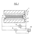
- Figure 1 shows a cross section of the electrochromic glazing according to the invention.
- the glazing 1 is made up of two glass substrates 3, of two layers transparent electroconductive 4, of an electrode of cathode electrochromic material 5, an electrolyte layer 6 and a counter electrode 7 made of electrochromic material anodic.
- Two current leads 2 are provided to supply the layers conductive 4. These are metal strips diagonally opposite and parallel to the length of glazing.
- the peripheral seal was not shown.
- the power supply circuit is shown very schematically. he comprises an intensity generator 8 and a voltage measurement means 9.
- the generator 8 is controlled by a control unit 10 which has the primary function of determining adequate intensity taking into account the size of the glazing, the contrast to be obtained and the desired switching time.
- a control unit 10 which has the primary function of determining adequate intensity taking into account the size of the glazing, the contrast to be obtained and the desired switching time.
- the control unit uses the information data by the voltage measuring means 9.
- the solution is poured under an atmosphere with controlled humidity (lower or equal at 50 ppm water) by the film-pull method on the substrate covered with one or other of the layers of electrochromic material.
- the solvent is then evaporated at room temperature in dry air for 20 hours.
- a comparative example has been produced, with an Ibis glazing unit having a stack and materials identical in all respects to the example according to the invention.
- the only change is the power supply, which is this time designed according to patent application EP-A-408,427, to which we will refer for more details.
- a voltage generator is used in place of the intensity generator 8 and the conductive layers are provided with a third current supply known as the reference point facing one of the first two, with a potentiostat type assembly: for switch the glazing, a voltage U is imposed between the two diametrically opposite current leads 2, using the voltage generator, voltage whose value is modulated as a function of the potential value U 2 known as the setpoint measured between l 'one of the leads and the third lead which faces it and which is of reference.
- the adaptation of U 1 as a function of U 2 normally allows the system to be kept in its electrochemical stability range.
- a first series of experiments was carried out with the two glazings.
- the objective is to cycle these, that is to say to make them pass from the discolored state to the colored state then back to the discolored state, by imposing a contrast C equal to 5 between discolored state and state colored, and at three different temperatures: 0, 20 and 80 ° C.
- the glazing supplied 1 is imposed in the coloring phase a intensity of -28 mA and in the discoloration phase an intensity of +28 mA, intensity previously calculated by the control unit to obtain sufficient cation transfer for the desired contrast and depending on the size of the glazing, control unit to which we have fixed the desired switching time, here 6 minutes.
- a voltage U 1 is imposed in the coloring phase by the voltage generator such that the set potential U 2 is maintained at a value of -1.6 volts.
- U 1 is imposed by the generator in order to maintain the set voltage U 2 at a value of +1.0 volts.
- the power supply according to the invention makes it possible to set a time setpoint perfectly independent of the operating temperature, which is far from to be the case for example 1 bis which where there is a factor of almost 50 between the time of switching at 0 and 80 ° C.
- Example 1a the value of 1 minute has been put in parenthesis for the time of staining of Example 1a at 80 ° C., to indicate that after ten or so the glazing was badly damaged (due to the lack of a reduction in the tension of instruction) which, to a large extent, is not for example 1 according to the invention.
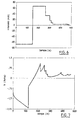
- the graph in Figure 2 represents the time (in seconds) on the x-axis and in ordered the electrical intensity (in mA).
- the solid line curve is that relating to Example 1, that in dotted lines in Example 1a.
- the first 150 seconds correspond to the coloring of the glazing, the next 150 to their discoloration.
- the graph in Figure 3 is similar to the previous one, but here the ordinate no longer corresponds to the intensity but to the electric voltage (in volts).
- the electric voltage in volts.
- 1 bis it is the voltage U 1 generated by the generator and taking into account the voltage U 2 setpoint.
- the glazing according to Example 1 easily succeeds in presenting an equal contrast 5.
- the glazing according to example 1a turns out to be incapable of presenting a contrast greater than 1.5, which can be seen quite well on the graph in Figure 2 where the curve intensity of example 1 bis indicates much lower values, in absolute value, than the intensity curve of Example 1: the transfer of charges and therefore of cations in the glazing of Example 1a was very incomplete, both in coloring and in discoloration.
- the power supply according to the invention makes it possible to keep the glazing its performance at low temperature, which makes it possible to consider using it in building facades without having to provide means to protect it from the cold, or even to heat. Furthermore, this power supply leaves the user free to a certain extent. the choice of switching time.
- the contrast of 5 can be obtained according to the invention at 0 ° C in 6 minutes as well as two and a half minutes, but of course the intensities to be generated must be increased in the same proportions.
- the glazing according to Comparative Example 1 has a marked "edge” phenomenon: the color change starts at the periphery to gradually win the game central of the glazing, there is no uniform change in color over the entire glazing.
- the glazing according to example 1 hardly exhibits this phenomenon: it is a significant aesthetic advantage.
- the last experiment carried out at 20 ° C by choosing a switching time of 150 seconds subjects the glazing according to Example 1 to an intensity supply by the generator 8 controlled by the control unit 10, which also regulates it according to the voltage measured by the measuring means 9 in order to guarantee the electrochemical stability of the glazing.
- regulation is only carried out in the fading phase, which is in fact the most critical because it is experimentally, the one where there can be tensions enough high to risk generating degrading parasitic reactions.
- the regulation in the bleaching phase is carried out, schematically, in the following manner: the intensity applied by the generator is that determined by the unit 10, as before, to transfer the number of cations desired in a given time. Then, during all the discoloration, the measuring means 9 "informs" the control unit 10 of the voltage across the glazing, at a given time interval (almost continuously). The control unit then calculates for each voltage measurement supplied its second derivative with respect to time. As soon as it reaches a set value, here fixed at 0.5 mV.s -2 , the control unit 10 forces the intensity generator 8 to reduce the intensity value it delivers by a factor of 2 .
- the control unit finally cuts off the power completely, either when the intensity value reaches a very low set value, close to zero, or when the output has reached a 100% set value.
- the power supply is cut for an intensity of less than 0.3 mA, which corresponds to an efficiency of 99.8%.
- the graph in Figure 6 clearly shows this regulation by stepwise reduction of intensity.
- the graph of figure 7 always represents the time in seconds on the abscissa and the voltage in volts on the ordinate.
- the invention is in no way limited to systems proton. To show it, comparative tests between a diet potentiostatic and an intensiostatic supply according to the invention were carried out with a second type of electrochromic glazing which, for its part, works by inserting ions lithium.
- the method according to the invention consists in forcing the passage of a quantity suitable fillers, quantity which depends exclusively on the nature of the layers of material electrochromic and the degree of color change desired.
- this amount of charges is completely independent of the ionic resistance of the electrolyte: it is thus possible to supply electrochromic systems with a relatively electrolyte bad ionic conductor without increasing switching times: it is important only that this conductivity is not zero, in theory.
- the voltage corresponding to the intensity of current imposed remains within reasonable limits, which implies in particular values compatible with safety, the type of electrical network available. It is necessary also take into account the heating of the system due to the Joule effect. However, these limits still allow great freedom in the choice offered, the tensions applied actually being able to vary for example between 1 and 100 volts.
- new ionic conductive polymers may possibly be used, the ionic conductivity of which is for example less than 10 -6 Ohm -1 .cm -1 at 20 ° C, the selection focusing in particular on polymers with the best mechanical properties. This also amounts to lowering the minimum temperature for using the electrochromic system.
- this amount of charge does not depend on the layers transparent electroconductive: layers with a square resistance greater than 15 Ohms for example with a square resistance of the order of 20-25 Ohms can thus be used while maintaining satisfactory switching times, simply the edge effect phenomenon will be all the more sensitive as the resistivity of the layers conductive is great.
- an electrochromic glazing of 40 ⁇ 80 cm 2 was produced , the electronically conductive layers 4 of which have a square resistance of 17 Ohms.
- a contrast of 3 is obtained in the center after 10 minutes.
- the contrast in the center is equal to 5.
- this quantity of charges is relatively independent of the state of aging of the system and of production fluctuations (this remains true as long as the quantity of charges imposed remains less than or equal to the capacity material insertion): this point ensures constant performance levels - in terms of switching speed - even with glazing of different ages (replacement of one of the windows of a facade for example).
- the intensiostatic feeding leads to the whole with lower electrical consumption, for a given intensity, the applied voltage is lower (in absolute value), the power is therefore smaller.
Landscapes
- Physics & Mathematics (AREA)
- Nonlinear Science (AREA)
- General Physics & Mathematics (AREA)
- Optics & Photonics (AREA)
- Electrochromic Elements, Electrophoresis, Or Variable Reflection Or Absorption Elements (AREA)
Description
- figure 1 : une représentation en coupe d'un vitrage électrochrome selon l'invention,
- figures 2 et 3 : des représentations à 0°C de l'évolution respectivement de l'intensité et de la tension d'un vitrage alimenté par un générateur d'intensité selon l'invention et d'un vitrage comparatif par un générateur de tension pendant un cycle de coloration/décoloration,
- figures 4 et 5 : les mêmes représentations mais à 20°C
- figures 6 et 7 : des représentations de l'évolution de l'intensité et de la tension à 20°C pendant un cycle de coloration/décoloration dans le cas où l'intensité est régulée en fonction des « brusques »variations de tension.
- substrat en verre 3 : feuilles de verre float de 1,5 mm d'épaisseur, de dimensions 30 x 30 cm2,
- couches électroconductrices 4 : oxyde d'indium dopé à l'étain, déposé par pulvérisation cathodique magnétron, d'épaisseur 400 nanomètres et de résistance carrée égale à 8 ohms,
- matériau électrochrome cathodique 5 : oxyde de tungstène WO3 déposé par pulvérisation cathodique magnétron réactive à partir d'une cible en tungstène en présence d'oxygène sous une pression de 20 millitorrs (soit 2,66 Pa), d'épaisseur 300 nm,
- matériau électrochrome anodique 7 : oxyde d'iridium, déposé par pulvérisation cathodique assistée par champ magnétique, sous une pression de 6 millitorrs (soit 0,8 Pa) d'un mélange gazeux oxygène/hydrogène dans un rapport volumique 80/20, d'épaisseur 55 nanomètres,
- électrolyte 6 : solution solide d'acide phosphorique anhydre dans un polyoxyéthylène, d'épaisseur 80 micromètres, de conductivité à 20°C de 9.10-6 ohm-1.cm-1 et de transmission lumineuse supérieure à 85 %. Il est préparé de la manière suivante : dans des conditions anhydres, on dissout par litre de solvant de l'acide phosphorique anhydre (21,5g) et du polyoxyéthylène de masse moléculaire 5 000 000 (densité 1,21) ; température de transition vitreuse -40°C ; rapport O/H du nombre d'atomes d'oxygène du polymère sur le nombre d'atomes d'hydrogène de l'acide égal à 0,66. Le solvant est un mélange 60/40 en volume d'acétonitrile et de tétrahydrofurane.
| TEMPERATURE | TEMPS DE REPONSE (ex. 1) | TEMPS DE REPONSE (ex. 1bis) |
| 0°C | 6 | 47 |
| 20°C | 6 | 3 |
| 80°C | 6 | (1) |
- substrat en verre 3 : feuilles de verre float de 1,5 mm d'épaisseur, de dimensions 10 x 15 cm2,
- couches électroconductrices 4 : oxyde d'indium dopé à l'étain, déposé par pulvérisation cathodique magnétron, d'épaisseur 400 nanomètres et de résistance carrée égale à 8 ohms,
- matériau électrochrome cathodique 5 : oxyde de tungstène WO3 déposé par pulvérisation cathodique magnétron réactive à partir d'une cible en tungstène en présence d'oxygène sous une pression de 20 millitorrs (soit 2,66 Pa), d'épaisseur 300 nm,
- matériau électrochrome anodique 7 : oxyde de nickel déposé par pulvérisation cathodique assistée par champ magnétique, sous une pression de 3,33 Pa d'un mélange gazeux oxygène/hydrogène dans un rapport volumique 80/20 d'épaisseur 200 nm. Cette contre-électrode est formatée électrochimiquement dans une solution carbone de propylène-sel LiClO4 afin d'y préinsérer des ions lithium avant l'assemblage du système,
- électrolyte - : polyoxyéthylène dopé au triflate de lithium sur une épaisseur de 80 micromètres.
| TEMPERATURE | MONTAGE POTENTIOSTATIQUE | MONTAGE INTENSIOSTATIQUE |
| 0°C | 20 min | 5 min |
| 20°C | 5 min | 5 min |
| 80°C | 2 min | 5 min |
Claims (13)
- Procédé d'alimentation électrique d'un système électrochrome (1) comportant un matériau dont l'état de coloration et/ou la transmission dans certaines longueurs d'onde de rayonnement électromagnétique varie par la mise en jeu d'une réaction électrochimique impliquant le passage d'un courant électrique, ledit courant électrique étant généré par un générateur d'intensité (8) apte à délivrer un courant dont l'intensité obéit à une valeur de consigne déterminée en fonction du nombre de charges à transférer pour commuter de l'état initial à l'état voulu et en fonction de la durée choisie pour la commutation, caractérisé en ce qu'on régule l'intensité générée, au moins quand le changement de coloration est une décoloration, en la maintenant inférieure, en valeur absolue, à l'intensité correspondant à une tension et/ou à une variation de tension susceptible de conduire à une dégradation du système.
- Procédé selon la revendication 1, caractérisé en ce que la détermination de l'intensité à générer s'effectue indépendamment de la température d'utilisation du système.
- Procédé selon l'une des revendications précédentes, caractérisé en ce que les moyens de détermination et/ou de régulation des intensités à délivrer par le générateur (8) comprennent tout moyen (10) informatique et/ou électronique.
- Procédé selon l'une des revendications précédentes, caractérisé en ce qu'on régule l'intensité en mesurant la tension dans le circuit, en déterminant, à intervalle de temps donné, sa dérivée seconde par rapport au temps et en imposant une diminution de l'intensité quand ladite dérivée seconde atteint une valeur consigne.
- Procédé selon l'une des revendications précédentes, caractérisé en ce qu'on régule l'intensité en mesurant la tension dans le circuit ou en calculant, à partir de la mesure de la tension, sa dérivée première par rapport au temps, à intervalle de temps donné, et en imposant une diminution de l'intensité générée quand ladite tension ou ladite dérivée atteint une valeur consigne déterminée à partir des mesures/calculs de la tension ou de sa dérivée effectués depuis le début de changement de coloration du système.
- Procédé selon l'une des revendications précédentes, caractérisé en ce qu'on coupe l'alimentation en intensité quand elle atteint une valeur minimale consigne, quand le rendement est de 100% ou quand l'état de coloration du système a atteint une valeur consigne.
- Procédé selon l'une des revendications précédentes, caractérisé en ce que la connexion électrique des couches électroconductrices (3) du système électrochrome (1) au circuit de commande électrique est réalisée en deux points d'amenée du courant situés sur chacune desdites couches (3), chacun de ces points alimentant un réseau conducteur en contact avec la couche conductrice concernée.
- Procédé selon la revendication 7, caractérisé en ce que la connexion électrique des couches électroconductrices (3) du système électrochrome (1) au circuit de commande électrique est réalisée uniquement par deux bandes conductrices d'amenée (2) déposées sur un bord de chacune des couches (3) et qui sont diamétralement opposées.
- Procédé selon l'une des revendications précédentes, caractérisé en ce qu'il s'applique à un système électrochrome comportant deux substrats transparents (3) du type feuilles de verre, revêtus de deux couches électroconductrices transparentes (4) séparées par une électrode formée par une couche d'un matériau électrochrome (5), un électrolyte (6) et une contre-électrode (7), le générateur (8) étant relié aux deux couches électroconductrices (4).
- Procédé selon la revendication 9, caractérisé en ce que les couches électroniquement conductrices du système électrochrome (1) ont une résistance carrée supérieure à 15 ohms.
- Procédé selon la revendication 9 ou 10, caractérisé en ce que la conductivité ionique de l'électrolyte du système électrochrome (1) à 20°C est inférieure à 10-6 Ohm-1.cm-1.
- Procédé selon l'une des revendications précédentes, caractérisé en ce qu'il s'applique à un système électrochrome « tout solide ».
- Procédé selon l'une des revendications 1 à 8, caractérisé en ce qu'il s'applique à un système viologène.
Applications Claiming Priority (2)
| Application Number | Priority Date | Filing Date | Title |
|---|---|---|---|
| FR9405948A FR2719915B1 (fr) | 1994-05-16 | 1994-05-16 | Système électrochrome et son procédé d'alimentation. |
| FR9405948 | 1994-05-16 |
Publications (2)
| Publication Number | Publication Date |
|---|---|
| EP0683419A1 EP0683419A1 (fr) | 1995-11-22 |
| EP0683419B1 true EP0683419B1 (fr) | 2003-01-02 |
Family
ID=9463221
Family Applications (1)
| Application Number | Title | Priority Date | Filing Date |
|---|---|---|---|
| EP95401122A Expired - Lifetime EP0683419B1 (fr) | 1994-05-16 | 1995-05-15 | Procédé d'alimentation d'un système électrochrome |
Country Status (6)
| Country | Link |
|---|---|
| US (1) | US5694144A (fr) |
| EP (1) | EP0683419B1 (fr) |
| JP (2) | JPH08313940A (fr) |
| CA (1) | CA2149485A1 (fr) |
| DE (1) | DE69529246T2 (fr) |
| FR (1) | FR2719915B1 (fr) |
Families Citing this family (69)
| Publication number | Priority date | Publication date | Assignee | Title |
|---|---|---|---|---|
| EP0879440A1 (fr) * | 1996-02-02 | 1998-11-25 | Pilkington Plc | Dispositifs electrochromes |
| US6369934B1 (en) * | 1996-05-30 | 2002-04-09 | Midwest Research Institute | Self bleaching photoelectrochemical-electrochromic device |
| FR2751097B1 (fr) * | 1996-07-10 | 1998-09-11 | Saint Gobain Vitrage | Elements a proprietes optiques/energetiques variables |
| JP4460078B2 (ja) * | 1996-10-17 | 2010-05-12 | サン−ゴバン グラス フランス | グレージング集成体 |
| DE19706918A1 (de) * | 1997-02-20 | 1998-08-27 | Flachglas Ag | Verfahren zum Betreiben eines elektrochromen Elementes |
| US6317248B1 (en) * | 1998-07-02 | 2001-11-13 | Donnelly Corporation | Busbars for electrically powered cells |
| US7020879B1 (en) * | 1998-12-16 | 2006-03-28 | Mips Technologies, Inc. | Interrupt and exception handling for multi-streaming digital processors |
| US6222177B1 (en) | 1999-01-19 | 2001-04-24 | Gentex Corporation | Electrochromic element driver with negative output resistance |
| DE19919750C1 (de) * | 1999-04-29 | 2001-01-18 | Flabeg Gmbh | Steuerverfahren für elektrochrome Verglasungen |
| FR2811778B1 (fr) * | 2000-07-13 | 2003-06-20 | Saint Gobain | Dispositif electrochimique du type electrochrome ou dispositif photovoltaique et ses moyens de connexion electrique |
| WO2003079463A2 (fr) * | 2002-03-15 | 2003-09-25 | Axon Technologies Corporation | Structure programmable, reseau comprenant cette structure et procedes de production de celle-ci |
| FR2857617B1 (fr) * | 2003-07-16 | 2006-10-27 | Saint Gobain | Vitrage de securite fonctionnalise |
| US7133181B2 (en) * | 2004-07-23 | 2006-11-07 | Sage Electrochromics, Inc. | Control system for electrochromic devices |
| FR2882828B1 (fr) * | 2005-03-03 | 2007-04-06 | Saint Gobain | Procede d'alimentation d'un dispositif electrocommandable a proprietes optiques et/ou energetiques variables |
| US9664974B2 (en) | 2009-03-31 | 2017-05-30 | View, Inc. | Fabrication of low defectivity electrochromic devices |
| US10303035B2 (en) | 2009-12-22 | 2019-05-28 | View, Inc. | Self-contained EC IGU |
| US11592723B2 (en) | 2009-12-22 | 2023-02-28 | View, Inc. | Automated commissioning of controllers in a window network |
| US11314139B2 (en) | 2009-12-22 | 2022-04-26 | View, Inc. | Self-contained EC IGU |
| US8213074B1 (en) | 2011-03-16 | 2012-07-03 | Soladigm, Inc. | Onboard controller for multistate windows |
| US10690540B2 (en) | 2015-10-06 | 2020-06-23 | View, Inc. | Multi-sensor having a light diffusing element around a periphery of a ring of photosensors |
| US20130271813A1 (en) | 2012-04-17 | 2013-10-17 | View, Inc. | Controller for optically-switchable windows |
| ES2450520T5 (es) | 2010-03-05 | 2017-08-07 | Sage Electrochromics, Inc. | Laminado de un dispositivo electrocrómico a sustratos de vidrio |
| FR2962682B1 (fr) | 2010-07-16 | 2015-02-27 | Saint Gobain | Vitrage electrochimique a proprietes optiques et/ou energetiques electrocommandables |
| US8705162B2 (en) | 2012-04-17 | 2014-04-22 | View, Inc. | Controlling transitions in optically switchable devices |
| US10935865B2 (en) | 2011-03-16 | 2021-03-02 | View, Inc. | Driving thin film switchable optical devices |
| US9778532B2 (en) | 2011-03-16 | 2017-10-03 | View, Inc. | Controlling transitions in optically switchable devices |
| US11630367B2 (en) | 2011-03-16 | 2023-04-18 | View, Inc. | Driving thin film switchable optical devices |
| US11822202B2 (en) | 2011-03-16 | 2023-11-21 | View, Inc. | Controlling transitions in optically switchable devices |
| US9454055B2 (en) | 2011-03-16 | 2016-09-27 | View, Inc. | Multipurpose controller for multistate windows |
| US9030725B2 (en) | 2012-04-17 | 2015-05-12 | View, Inc. | Driving thin film switchable optical devices |
| US9412290B2 (en) | 2013-06-28 | 2016-08-09 | View, Inc. | Controlling transitions in optically switchable devices |
| US8254013B2 (en) | 2011-03-16 | 2012-08-28 | Soladigm, Inc. | Controlling transitions in optically switchable devices |
| US11054792B2 (en) | 2012-04-13 | 2021-07-06 | View, Inc. | Monitoring sites containing switchable optical devices and controllers |
| US9645465B2 (en) | 2011-03-16 | 2017-05-09 | View, Inc. | Controlling transitions in optically switchable devices |
| TWI477847B (zh) * | 2011-09-30 | 2015-03-21 | Ibm | 透明度調整裝置及具有該透明度調整裝置的顯示系統 |
| CN103987909B (zh) | 2011-10-21 | 2017-03-22 | 唯景公司 | 减轻可着色窗中的热冲击 |
| US12578609B2 (en) | 2012-03-13 | 2026-03-17 | View Operating Corporation | Methods of controlling multi-zone tintable windows |
| US11635666B2 (en) | 2012-03-13 | 2023-04-25 | View, Inc | Methods of controlling multi-zone tintable windows |
| US11950340B2 (en) | 2012-03-13 | 2024-04-02 | View, Inc. | Adjusting interior lighting based on dynamic glass tinting |
| US12400651B2 (en) | 2012-04-13 | 2025-08-26 | View Operating Corporation | Controlling optically-switchable devices |
| US10964320B2 (en) | 2012-04-13 | 2021-03-30 | View, Inc. | Controlling optically-switchable devices |
| US12619118B2 (en) | 2012-04-13 | 2026-05-05 | View Operating Corporation | Controlling transitions in optically switchable devices |
| US9638978B2 (en) | 2013-02-21 | 2017-05-02 | View, Inc. | Control method for tintable windows |
| US10503039B2 (en) | 2013-06-28 | 2019-12-10 | View, Inc. | Controlling transitions in optically switchable devices |
| US11674843B2 (en) | 2015-10-06 | 2023-06-13 | View, Inc. | Infrared cloud detector systems and methods |
| US10048561B2 (en) | 2013-02-21 | 2018-08-14 | View, Inc. | Control method for tintable windows |
| US11300848B2 (en) | 2015-10-06 | 2022-04-12 | View, Inc. | Controllers for optically-switchable devices |
| EP3223532B1 (fr) | 2012-04-13 | 2019-10-09 | View, Inc. | Applications pour commander des dispositifs commutables optiquement |
| US11960190B2 (en) | 2013-02-21 | 2024-04-16 | View, Inc. | Control methods and systems using external 3D modeling and schedule-based computing |
| US12372846B2 (en) | 2013-02-21 | 2025-07-29 | View Operating Corporation | Control methods and systems using external 3D modeling and schedule-based computing |
| US11966142B2 (en) | 2013-02-21 | 2024-04-23 | View, Inc. | Control methods and systems using outside temperature as a driver for changing window tint states |
| US12422725B2 (en) | 2013-02-21 | 2025-09-23 | View Operating Corporation | Control methods and systems using outside temperature as a driver for changing window tint states |
| US11719990B2 (en) | 2013-02-21 | 2023-08-08 | View, Inc. | Control method for tintable windows |
| US12353111B2 (en) | 2013-06-28 | 2025-07-08 | View Operating Corporation | Controlling transitions in optically switchable devices |
| US12061404B2 (en) | 2013-06-28 | 2024-08-13 | View, Inc. | Controlling transitions in optically switchable devices |
| US9885935B2 (en) | 2013-06-28 | 2018-02-06 | View, Inc. | Controlling transitions in optically switchable devices |
| US10221612B2 (en) | 2014-02-04 | 2019-03-05 | View, Inc. | Infill electrochromic windows |
| KR102336168B1 (ko) | 2014-03-05 | 2021-12-07 | 뷰, 인크. | 스위칭가능한 광 디바이스들 및 제어기들을 포함하는 사이트들 모니터링 |
| TWI746446B (zh) | 2015-07-07 | 2021-11-21 | 美商唯景公司 | 用於可著色窗戶之控制方法 |
| US11255722B2 (en) | 2015-10-06 | 2022-02-22 | View, Inc. | Infrared cloud detector systems and methods |
| AU2016346328B2 (en) | 2015-10-29 | 2022-04-28 | View, Inc. | Controllers for optically-switchable devices |
| EP4130865B1 (fr) | 2016-04-29 | 2025-10-22 | View, Inc. | Étalonnage de paramètres électriques dans des fenêtres optiquement commutables |
| US11513412B2 (en) | 2017-04-26 | 2022-11-29 | View, Inc. | Displays for tintable windows |
| CN112470065B (zh) * | 2018-07-31 | 2024-08-13 | Sage电致变色显示有限公司 | 电化学设备及其形成方法 |
| US11631493B2 (en) | 2020-05-27 | 2023-04-18 | View Operating Corporation | Systems and methods for managing building wellness |
| TW202206925A (zh) | 2020-03-26 | 2022-02-16 | 美商視野公司 | 多用戶端網路中之存取及傳訊 |
| CN112083613A (zh) * | 2020-09-17 | 2020-12-15 | 努比亚技术有限公司 | 电致变色膜驱动控制方法、设备及计算机可读存储介质 |
| US20230229051A1 (en) * | 2022-01-18 | 2023-07-20 | Furcifer Inc. | Method and device for controlling states of dynamic glass |
| CN117311050A (zh) * | 2023-11-09 | 2023-12-29 | 苏州伯宇光电科技有限公司 | 无级调节电致变色片透过率方法及系统 |
Family Cites Families (9)
| Publication number | Priority date | Publication date | Assignee | Title |
|---|---|---|---|---|
| CH609468A5 (fr) * | 1976-05-24 | 1979-02-28 | Sharp Kk | |
| DE2825390C2 (de) * | 1977-06-14 | 1983-01-05 | Sharp K.K., Osaka | Treiberschaltung für eine elektrochrome Anzeigevorrichtung |
| FR2432195A1 (fr) * | 1978-06-19 | 1980-02-22 | Commissariat Energie Atomique | Procede de commande d'une cellule electrolytique a l'aide d'une grandeur electrique asservie a une electrode de reference et dispositif de mise en oeuvre |
| JPS56151993A (en) * | 1980-04-25 | 1981-11-25 | Seiko Instr & Electronics | Electrochromatic display unit driving method |
| DE3142909A1 (de) * | 1981-10-29 | 1983-05-11 | Fa. Carl Zeiss, 7920 Heidenheim | Kontinuierliche ladungssteuerung fuer elektrochrome schichten |
| FR2649691B1 (fr) * | 1989-07-11 | 1992-10-30 | Saint Gobain Vitrage Int | Vitrage electrochrome |
| FR2666804B1 (fr) * | 1990-09-14 | 1993-05-28 | Saint Gobain Vitrage Int | Vitrage electrochrome. |
| FR2690763B1 (fr) * | 1992-04-30 | 1995-06-09 | Saint Gobain Vitrage Int | Procede et dispositif d'alimentation d'un systeme electrochrome. |
| FR2694820B1 (fr) * | 1992-08-12 | 1994-09-16 | Saint Gobain Vitrage Int | Alimentation d'une cellule électrochrome. |
-
1994
- 1994-05-16 FR FR9405948A patent/FR2719915B1/fr not_active Expired - Lifetime
-
1995
- 1995-05-15 DE DE69529246T patent/DE69529246T2/de not_active Expired - Lifetime
- 1995-05-15 US US08/441,295 patent/US5694144A/en not_active Expired - Lifetime
- 1995-05-15 EP EP95401122A patent/EP0683419B1/fr not_active Expired - Lifetime
- 1995-05-16 JP JP7117492A patent/JPH08313940A/ja not_active Withdrawn
- 1995-05-16 CA CA002149485A patent/CA2149485A1/fr not_active Abandoned
-
2005
- 2005-07-11 JP JP2005202064A patent/JP3943576B2/ja not_active Expired - Lifetime
Also Published As
| Publication number | Publication date |
|---|---|
| FR2719915A1 (fr) | 1995-11-17 |
| US5694144A (en) | 1997-12-02 |
| DE69529246T2 (de) | 2003-10-30 |
| JP2005338871A (ja) | 2005-12-08 |
| EP0683419A1 (fr) | 1995-11-22 |
| JP3943576B2 (ja) | 2007-07-11 |
| JPH08313940A (ja) | 1996-11-29 |
| FR2719915B1 (fr) | 1996-06-14 |
| DE69529246D1 (de) | 2003-02-06 |
| CA2149485A1 (fr) | 1995-11-17 |
Similar Documents
| Publication | Publication Date | Title |
|---|---|---|
| EP0683419A1 (fr) | Système électrochrome et son procédé d'alimentation | |
| EP0475847B1 (fr) | Vitrage électrochrome | |
| EP0584003B1 (fr) | Alimentation d'une cellule electrochrome | |
| EP0408427B1 (fr) | Vitrage électrochrome | |
| FR2728696A1 (fr) | Procede d'alimentation electrique d'un vitrage electrocommandable | |
| FR2690536A1 (fr) | Vitrage électrochrome. | |
| EP0253713B1 (fr) | Vitrage à transmission variable du type électrochrome | |
| EP1451634B1 (fr) | Electrode de dispositifs electrochimiques et/ou electrocommandables | |
| EP0486387A1 (fr) | Vitrage électrochrome | |
| WO2000003289A1 (fr) | Procede de traitement d'un dispositif electrochimique | |
| EP2374040A1 (fr) | Dispositif electrocommandable presentant un acheminement ameliore des charges electriques du milieu electro-actif | |
| WO2005103807A2 (fr) | Procédé d'alimentation d'un dispositif électrocommandable à propriétés optiques et/ou énergétiques variables | |
| WO2012089955A1 (fr) | Dispositif electrochimique a proprietes de transmission optique et/ou energetique electrocommandables | |
| EP0373020B1 (fr) | Contre-électrode pour systèmes électrochromes | |
| FR2669122A1 (fr) | Vitrage electrochrome. | |
| EP0006811A2 (fr) | Cellule d'affichage électrolytique à dépôt métallique et procédé pour éviter un appauvrissement en métal de certaines zones de la contre-électrode d'une telle cellule | |
| WO2010004158A1 (fr) | Electrode isolante pour dispositif électrochimique | |
| EP0557159A1 (fr) | Système électrochrome | |
| JPH09127558A (ja) | エレクトロクロミック素子 | |
| EP0065894A1 (fr) | Cellule d'affichage électrolytique à lame arrière transparente | |
| FR2977040A1 (fr) | Procede de fabrication d'un dispositif electrochimique a proprietes de transmission optique et/ou energetique electrocommandables | |
| FR2720842A1 (fr) | Couche de matériau électrochrome anodique et son procédé de fabrication. |
Legal Events
| Date | Code | Title | Description |
|---|---|---|---|
| PUAI | Public reference made under article 153(3) epc to a published international application that has entered the european phase |
Free format text: ORIGINAL CODE: 0009012 |
|
| AK | Designated contracting states |
Kind code of ref document: A1 Designated state(s): BE DE FR GB IT SE |
|
| 17P | Request for examination filed |
Effective date: 19960520 |
|
| 17Q | First examination report despatched |
Effective date: 20000918 |
|
| RTI1 | Title (correction) |
Free format text: METHOD OF SUPPLYING POWER TO AN ELECTROCHROMIC SYSTEM |
|
| GRAH | Despatch of communication of intention to grant a patent |
Free format text: ORIGINAL CODE: EPIDOS IGRA |
|
| RTI1 | Title (correction) |
Free format text: METHOD OF SUPPLYING POWER TO AN ELECTROCHROMIC SYSTEM |
|
| RAP1 | Party data changed (applicant data changed or rights of an application transferred) |
Owner name: SAINT-GOBAIN GLASS FRANCE |
|
| GRAH | Despatch of communication of intention to grant a patent |
Free format text: ORIGINAL CODE: EPIDOS IGRA |
|
| GRAA | (expected) grant |
Free format text: ORIGINAL CODE: 0009210 |
|
| AK | Designated contracting states |
Kind code of ref document: B1 Designated state(s): BE DE FR GB IT SE |
|
| REG | Reference to a national code |
Ref country code: GB Ref legal event code: FG4D Free format text: 20030102:NOT ENGLISH |
|
| REF | Corresponds to: |
Ref document number: 69529246 Country of ref document: DE Date of ref document: 20030206 Kind code of ref document: P |
|
| REG | Reference to a national code |
Ref country code: SE Ref legal event code: TRGR |
|
| GBT | Gb: translation of ep patent filed (gb section 77(6)(a)/1977) |
Effective date: 20030424 |
|
| PLBE | No opposition filed within time limit |
Free format text: ORIGINAL CODE: 0009261 |
|
| STAA | Information on the status of an ep patent application or granted ep patent |
Free format text: STATUS: NO OPPOSITION FILED WITHIN TIME LIMIT |
|
| 26N | No opposition filed |
Effective date: 20031003 |
|
| PGFP | Annual fee paid to national office [announced via postgrant information from national office to epo] |
Ref country code: GB Payment date: 20140514 Year of fee payment: 20 |
|
| PGFP | Annual fee paid to national office [announced via postgrant information from national office to epo] |
Ref country code: IT Payment date: 20140515 Year of fee payment: 20 Ref country code: DE Payment date: 20140507 Year of fee payment: 20 Ref country code: SE Payment date: 20140513 Year of fee payment: 20 |
|
| PGFP | Annual fee paid to national office [announced via postgrant information from national office to epo] |
Ref country code: BE Payment date: 20140527 Year of fee payment: 20 |
|
| PGFP | Annual fee paid to national office [announced via postgrant information from national office to epo] |
Ref country code: FR Payment date: 20140526 Year of fee payment: 20 |
|
| REG | Reference to a national code |
Ref country code: DE Ref legal event code: R071 Ref document number: 69529246 Country of ref document: DE |
|
| REG | Reference to a national code |
Ref country code: GB Ref legal event code: PE20 Expiry date: 20150514 |
|
| REG | Reference to a national code |
Ref country code: SE Ref legal event code: EUG |
|
| PG25 | Lapsed in a contracting state [announced via postgrant information from national office to epo] |
Ref country code: GB Free format text: LAPSE BECAUSE OF EXPIRATION OF PROTECTION Effective date: 20150514 |