EP0683373A1 - Heat exchanger and method of making same - Google Patents
Heat exchanger and method of making same Download PDFInfo
- Publication number
- EP0683373A1 EP0683373A1 EP95107268A EP95107268A EP0683373A1 EP 0683373 A1 EP0683373 A1 EP 0683373A1 EP 95107268 A EP95107268 A EP 95107268A EP 95107268 A EP95107268 A EP 95107268A EP 0683373 A1 EP0683373 A1 EP 0683373A1
- Authority
- EP
- European Patent Office
- Prior art keywords
- tank
- partition
- bottom wall
- heat exchanger
- upper wall
- Prior art date
- Legal status (The legal status is an assumption and is not a legal conclusion. Google has not performed a legal analysis and makes no representation as to the accuracy of the status listed.)
- Granted
Links
Images


Classifications
-
- F—MECHANICAL ENGINEERING; LIGHTING; HEATING; WEAPONS; BLASTING
- F28—HEAT EXCHANGE IN GENERAL
- F28F—DETAILS OF HEAT-EXCHANGE AND HEAT-TRANSFER APPARATUS, OF GENERAL APPLICATION
- F28F9/00—Casings; Header boxes; Auxiliary supports for elements; Auxiliary members within casings
- F28F9/02—Header boxes; End plates
- F28F9/0202—Header boxes having their inner space divided by partitions
- F28F9/0204—Header boxes having their inner space divided by partitions for elongated header box, e.g. with transversal and longitudinal partitions
- F28F9/0207—Header boxes having their inner space divided by partitions for elongated header box, e.g. with transversal and longitudinal partitions the longitudinal or transversal partitions being separate elements attached to header boxes
-
- B—PERFORMING OPERATIONS; TRANSPORTING
- B21—MECHANICAL METAL-WORKING WITHOUT ESSENTIALLY REMOVING MATERIAL; PUNCHING METAL
- B21D—WORKING OR PROCESSING OF SHEET METAL OR METAL TUBES, RODS OR PROFILES WITHOUT ESSENTIALLY REMOVING MATERIAL; PUNCHING METAL
- B21D53/00—Making other particular articles
- B21D53/02—Making other particular articles heat exchangers or parts thereof, e.g. radiators, condensers fins, headers
-
- F—MECHANICAL ENGINEERING; LIGHTING; HEATING; WEAPONS; BLASTING
- F28—HEAT EXCHANGE IN GENERAL
- F28D—HEAT-EXCHANGE APPARATUS, NOT PROVIDED FOR IN ANOTHER SUBCLASS, IN WHICH THE HEAT-EXCHANGE MEDIA DO NOT COME INTO DIRECT CONTACT
- F28D1/00—Heat-exchange apparatus having stationary conduit assemblies for one heat-exchange medium only, the media being in contact with different sides of the conduit wall, in which the other heat-exchange medium is a large body of fluid, e.g. domestic or motor car radiators
- F28D1/02—Heat-exchange apparatus having stationary conduit assemblies for one heat-exchange medium only, the media being in contact with different sides of the conduit wall, in which the other heat-exchange medium is a large body of fluid, e.g. domestic or motor car radiators with heat-exchange conduits immersed in the body of fluid
- F28D1/04—Heat-exchange apparatus having stationary conduit assemblies for one heat-exchange medium only, the media being in contact with different sides of the conduit wall, in which the other heat-exchange medium is a large body of fluid, e.g. domestic or motor car radiators with heat-exchange conduits immersed in the body of fluid with tubular conduits
- F28D1/053—Heat-exchange apparatus having stationary conduit assemblies for one heat-exchange medium only, the media being in contact with different sides of the conduit wall, in which the other heat-exchange medium is a large body of fluid, e.g. domestic or motor car radiators with heat-exchange conduits immersed in the body of fluid with tubular conduits the conduits being straight
- F28D1/05316—Assemblies of conduits connected to common headers, e.g. core type radiators
- F28D1/05341—Assemblies of conduits connected to common headers, e.g. core type radiators with multiple rows of conduits or with multi-channel conduits combined with a particular flow pattern, e.g. multi-row multi-stage radiators
-
- Y—GENERAL TAGGING OF NEW TECHNOLOGICAL DEVELOPMENTS; GENERAL TAGGING OF CROSS-SECTIONAL TECHNOLOGIES SPANNING OVER SEVERAL SECTIONS OF THE IPC; TECHNICAL SUBJECTS COVERED BY FORMER USPC CROSS-REFERENCE ART COLLECTIONS [XRACs] AND DIGESTS
- Y10—TECHNICAL SUBJECTS COVERED BY FORMER USPC
- Y10S—TECHNICAL SUBJECTS COVERED BY FORMER USPC CROSS-REFERENCE ART COLLECTIONS [XRACs] AND DIGESTS
- Y10S165/00—Heat exchange
- Y10S165/454—Heat exchange having side-by-side conduits structure or conduit section
- Y10S165/471—Plural parallel conduits joined by manifold
- Y10S165/481—Partitions in manifold define serial flow pattern for conduits/conduit groups
- Y10S165/482—Partitions are separate members
-
- Y—GENERAL TAGGING OF NEW TECHNOLOGICAL DEVELOPMENTS; GENERAL TAGGING OF CROSS-SECTIONAL TECHNOLOGIES SPANNING OVER SEVERAL SECTIONS OF THE IPC; TECHNICAL SUBJECTS COVERED BY FORMER USPC CROSS-REFERENCE ART COLLECTIONS [XRACs] AND DIGESTS
- Y10—TECHNICAL SUBJECTS COVERED BY FORMER USPC
- Y10T—TECHNICAL SUBJECTS COVERED BY FORMER US CLASSIFICATION
- Y10T29/00—Metal working
- Y10T29/49—Method of mechanical manufacture
- Y10T29/4935—Heat exchanger or boiler making
- Y10T29/49389—Header or manifold making
Definitions
- This invention relates to a heat exchanger and method for making a heat exchanger for use in an air conditioning system for vehicles, and more particularly, to a heat exchanger that allows for efficient and easy assembly.
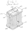
- Figs. 1 and 2 show a conventional heat exchanger used in an air conditioning system, for example, an evaporator or a condenser.
- a beat exchanger comprises an upper tank 105, a lower tank 110 and heat exchanger core 115 disposed between the upper tank and the lower tank.
- the heat exchanger core 115 comprises a plurality of beat transfer tubes disposed parallel to one another.
- the upper tank 105 has an upper wall and a lower wall, which are connected to each other.
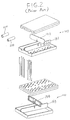
- the upper tank 105 is divided into three chambers by first partition plate 151 and second partition plate 152.
- First partition plate 151 and second partition plate 152 include respectively notched portions formed in the centers thereof.
- First partition plate 151 includes a plurality of holes therethrough.
- Lower tank 110 is divided into two chambers, such as first lower chamber and a second lower chamber, by partition plate 153. Further, the lower tank includes preventing overturn plate 154 therein. Preventing overturn plate 154 includes a notched portion formed in the center thereof and a plurality of holes therein. The number of holes formed in preventing overturn plate 154 as well as their respective diameter is determined so that a heat exchanger medium may pass freely through the holes.
- the lower wall of the upper tank 105 and the upper wall of the lower tank 110 are provided with a plurality of connection holes, respectively, for interconnecting a plurality of heat transfer tubes therebetween.
- An inlet pipe 210 and outlet pipe 220 are connected to the upper tank 105.
- first partition plate 151 is placed on the lower wall of the upper tank 105 so as to be located in the center of the lower wall of the upper tank 105 and second partition plate 152 is connected with first partition plate 151 at right angles to each other, so that the notched portion of second partition plate 152 fixedly inserts into the center notched portion of first partition plate 151 in an attempt to prevent movement and overturning during brazing.
- partition plate 153 is placed on the lower wall of the lower tank 110 so as to be located in the center of the lower wall of the lower tank 110.
- preventing overturn plate 154 is connected with partition plate 153 at a right angle, so that the notched portion of partition plate 153 fixedly inserts into the center notched portion of the preventing overturn plate 154 to prevent movement and overturning during brazing.
- the heat exchanger may be placed in a brazing furnace, so that all of its parts may be brazed together.
- the partition plates 151 and 153 tend to fall down until they are connected with their corresponding partition plate 152 or the preventing overturn plate 154 respectively. Further, the partition plates 151, 152 and 153 and the preventing overturn plate 154 tend to incline and move from the desired location unless these parts are formed to extremely precise sizes.
- a heat exchanger comprises a first tank with a second tank spaced vertically from the first tank.
- Each of the first and second tanks include a plurality of connection holes aligned in rows.
- the first tank includes first and second partitions disposed therein to divide the first tank into a first number of chambers, wherein the first number of chambers is at least two and has respectively an inlet to allow the heat transfer medium to enter the heat exchanger and an outlet to allow the heat transfer medium to exit the heat exchanger.
- the second tank includes a third partition disposed therein to divide the second tank into a second number of chambers, wherein the second number of chambers is preferably one less than the first number of chambers.
- a plurality of heat transfer tubes are fixedly disposed between the first tank and the second tank in fluid communication
- the first tank and the second tank respectively include concave portions horizontally formed on walls of the tanks, wherein ends of each of the first and second partitions respectively insert into each of the concave portions for preventing overturn of the partitions during assembly of the tanks.
- a heat exchanger according to the present invention may be constructed by one of the following preferred methods.
- the method of manufacturing a heat exchanger according to one preferred embodiment of the invention includes bending a plurality of planer raw plates to have U-shaped cross sections defining a flat portion as an upper wall and a bottom wall of the first and second tanks.
- a plurality of connection holes are formed on the flat portion of the bottom wall of the first tank and the upper wall of the second tank.
- Concave portions are then formed on the fiat portion of the upper wall and the bottom wall of the first tank, after which one end of the first partition is inserted into the concave portion of the bottom wall of the first tank and one end of the second partition is inserted into the concave portion of the bottom wall of the first tank so that the second partition is substantially perpendicular to the first partition.
- the upper wall of the first tank is placed on the bottom wall of the first tank so that a circumference of the upper wall is overlapped with the circumference of the bottom wall of the first tank, and other ends of the first partition and the second partition insert into the concave portions of the upper wall and the bottom wall of the first tank.
- One end of the third partition is then inserted into the concave portion of the bottom wall of the second tank, and the upper wall of the second tank is placed on the bottom wall of the second tank so that a circumference of the upper wall meets with a circumference of the bottom wall of the second tank.
- the other end of the third partition is next inserted into the concave portions of the upper wall and the bottom wall of the lower tank.
- the opposite end of the heat transfer tubes are inserted into the respective connection holes of the first tank and the second tank.
- the partition plates remain in plate during the assembly process. Further, these partition plates do not incline and/or move from a predetermined place even if the size of the parts, such as partition plates or walls of the tanks varies to some degree. In this way, partition plates are fixedly and securely connected with the tanks by bring because there are no gaps between these partition plates and the walls of the tanks. Further, the concave surfaces which are formed function to prevent the tanks from being deformed by pressure during operation. Further objects, features, and other aspects of this invention will be understood from the following detailed description of the preferred embodiments of this invention referring to the annexed drawings.
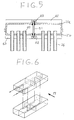
- FIG. 4 A heat exchanger in accordance with a first embodiment of the present invention is illustrated in Figs. 4 and 5.
- heat exchanger 20 comprises upper tank 21, lower tank 22 vertically spaced from upper tank 21 and heat exchanger core 23 disposed between upper tank 21 and lower tank 22.
- Heat exchanger core 23 comprise a plurality of heat transfer tubes 24 spaced from one another and disposed in paralleled to one another.
- Upper tank 21 includes upper wall 21a and bottom wall 21b, which are connected so as to form an enclosed tank.
- Upper wall 21a of upper tank 21 includes first concave surface 60 and second concave surface 61 formed inside of upper tank 21 and extending from one horizontal end to other horizontal end.
- First concave surface 60 and second concave surface 61 are formed to be U-shaped in cross section and are vertically projected toward the outside of upper tank 21. Further, first concave surface 60 and second concave surface 61 are formed to intersect each other and to be substantially perpendicular to each other so as to divide upper wall 21a into four areas.
- Bottom wall 21b of upper tank 21 includes third concave surface 62 and fourth concave surface 63 formed inside of upper tank 21.
- Third concave surface 62 and fourth concave surface 63 are formed to be U-shaped in cross section and are vertically projected toward the outside of upper tank 21. Further, third concave surface 62 and fourth concave surface 63 are formed to intersect each other and to be substantially perpendicular to each other so as to divide bottom wall 21b into four areas.
- Upper wall 22a of lower tank 22 includes concave surface 64 formed inside of lower tank 22.
- Bottom wall 22b of lower tank 22 includes concave surface 65 formed inside of lower tank 22.
- Concave surfaces 64 and 65 are formed to be U-shaped in cross section and are vertically projected toward the outside of lower tank 22. Further, concave surfaces 64 and 65 respectively divide upper wall 21a and bottom wall 22b into two areas.
- upper tank 21 includes end plates 21c and 21d respectively covering both ends of the cylindrical opening which are united with upper wall 21a and bottom wall 21b.
- Bottom wall 21b of upper tank 21 and upper wall 22a of lower tank 22 are provided with a plurality of connection holes 40 and 41, respectively, for interconnecting a plurality of heat transfer tubes 24 therebetween
- Upper tank 21 is divided into three chambers, such as first upper chamber 28, second upper chamber 29 and third upper chamber 30 by first partition plate 51 and second partition plate 52.
- Lower tank 22 is divided into two chambers such as first lower chamber 32 and second lower chamber 33, by partition plate 53 which is inserted into concave surfaces 64 and 65.
- Inlet pipe 45 and outlet pipe 46 are connected to upper tank 21.
- a heat exchanger medium may be introduced via inlet pipe 45 into first upper chamber 28 and may flow down through heat transfer tubes 24 until it reaches first lower chamber 32 of lower tank 22. The medium then may flow back into second upper chamber 29 through heat transfer tubes 24. Further, the heat exchanger medium may then flow from second upper chamber 29 of upper tank 21 through heat transfer tubes 24 into second lower chamber 33 of lower tank 22 and then back to third upper chamber 30 through heat transfer tubes 24. When the heat exchanger medium flows through heat transfer tubes 24, heat is exchanged between the heat exchanger medium and the air flow 17 passing across heat transfer tubes 24.
- first partition plate 51 includes notched portion 51a formed in the center thereof and a plurality of holes 51b therein.
- the plurality of holes 51b are formed with a predetermined number, pitch, and diameter, so that a heat exchanger medium may pass freely through holes 51b of first partition plate 51.
- Upper wall 21a and bottom wall 21b are formed to be U-shaped in cross section.
- Concave surfaces 60, 61, 62 and 63 may be formed by a press work.
- One long end of first partition 51 is inserted into third concave surface 62 of bottom wall 21b of upper tank 21 so as to be positioned in the center of upper tank 21.
- Second partition plate 52 is connected with first partition plate 51 at a right angle so the notched portion 52a of second partition plate 52 fixedly inserts into center notched portion 51a of first partition plate 51. Thereafter, upper wall 21a is placed on bottom wall 21b so that the other ends of partition plate 51 and 52 are respectively inserted into first concave surface 60 and second concave surface 61. Further, first end plate 21c and second end plate 21d are forcibly inserted into the openings which are formed by upper wall 21a and bottom wall 21b.
- partition plate 53 In assembling lower tank 22, one long end of partition plate 53 is inserted into concave surface 65 of bottom wall 22b of lower tank 22 so as to be positioned in the center of lower tank 22. Thereafter, upper wall 22a is placed on bottom wall 22b so that other end of partition plate 53 is inserted into concave surface 64. Further, first end plate 22c and second end plate 22d are forcibly inserted into the openings which are formed by upper wall 22a and bottom wall 22b.
- heat transfer tubes 24 are connected with upper tank 21 and lower tank 22 through connection holes 40 of bottom wall 21b and connection holes 41 of upper wall 22a Finally, assembled heat exchanger 10 may be placed in a brazing furnace, so that all of its parts may be simultaneously brazed together.
- first partition plate 51, second partition plate 52 of upper tank 21, and partition plate 53 of lower tank 53 do not fall down during the assembly process of the tanks. Further, these partition plates do not incline or move from a predetermined place even if the size of the parts, such as partition plates 51, 52, and 53, wall of upper tank 21 and lower tank 22 are not perfectly accurate.
- partition plates 51, 52, and 53 are fixedly and securely connected with upper tank 21 and lower tank 22 by brazing because there is no gap between these partition plates and walls of upper tank 21 and lower tank 22.
- the concave surfaces have a function which prevents the tanks from being deformed by pressure during operation or brazing.
- the heat exchanger of the present invention can be manufactured using a simple process and at a low cost in comparison with the prior art.
- FIGs. 8 and 9 illustrate a second embodiment of the present invention.
- upper wall 121a of upper tank 121 includes a first concave surface 70 and a second concave surface 71 formed inside of upper tank 121.
- the concave surfaces in this embodiment are formed in a box shape.
- First concave surface 70 and second concave surface 71 project toward the outside of upper tank 121 and are formed to be substantially perpendicular to each other so as to divide upper wall 121a into four areas.
- first concave surface 70 and second concave surface 71 include openings 70a and 71a respectively, formed outside of upper tank 121 by cutting out the top ends of concaves 70 and 71.
- Fig. 10 illustrates a method for forming a heat exchanger according to the second embodiment of this invention.
- Upper wall 121a is placed on bottom wall 121b so that they overlap.
- partition plate 51 is inserted into the inside of upper tank 121 through opening 70a.
- One long end of partition plate 51 may then be further inserted into concave 72.
- Second partition plate 52 may be inserted into upper tank 121 through opening 71a and connected with first partition plate 51 at right angles to each other, so that notched portion 52a of second partition plate 52 fixedly inserts into center notched portion 51a of first partition plate 51.
- One long end of partition plate 52 may be further inserted into concave 73 to prevent the movement thereof during brazing.
- partition plate 53 may be inserted into lower tank 122 through opening 74a. Partition plate is then further inserted into concave 75.
- substantially the same advantages as those in the first embodiment can be obtained.
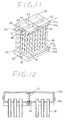
- Figs. 11 and 12 illustrate a third embodiment of the present invention.
- upper wall 21a of upper tank 21 does not include a concave surface inside of upper tank 21.
- bottom wall 21b of upper tank 21 includes a first concave surface 62 and second concave surface 63 vertically projecting toward the outside of upper tank 21 and formed to intersect and be substantially perpendicular to each other so as to divide bottom wall 21b into four areas.
- upper wall 22a of lower tank 22 does not include a concave surface.
- Bottom wall 22b of lower tank 22 includes concave surface 65 formed inside of lower tank 22. Concave surface 65 is formed to be U-shaped in cross section and vertically projects toward the outside of lower tank 22. Further, concave surface 65 divides bottom wall 22b of lower tank 22 into two areas.
Abstract
Description
- This invention relates to a heat exchanger and method for making a heat exchanger for use in an air conditioning system for vehicles, and more particularly, to a heat exchanger that allows for efficient and easy assembly.
- Figs. 1 and 2 show a conventional heat exchanger used in an air conditioning system, for example, an evaporator or a condenser. In Figs. 1 and 2, a beat exchanger comprises an
upper tank 105, alower tank 110 andheat exchanger core 115 disposed between the upper tank and the lower tank. Theheat exchanger core 115 comprises a plurality of beat transfer tubes disposed parallel to one another. Theupper tank 105 has an upper wall and a lower wall, which are connected to each other. Theupper tank 105 is divided into three chambers byfirst partition plate 151 andsecond partition plate 152.First partition plate 151 andsecond partition plate 152 include respectively notched portions formed in the centers thereof.First partition plate 151 includes a plurality of holes therethrough.Lower tank 110 is divided into two chambers, such as first lower chamber and a second lower chamber, bypartition plate 153. Further, the lower tank includes preventingoverturn plate 154 therein. Preventingoverturn plate 154 includes a notched portion formed in the center thereof and a plurality of holes therein. The number of holes formed in preventingoverturn plate 154 as well as their respective diameter is determined so that a heat exchanger medium may pass freely through the holes. The lower wall of theupper tank 105 and the upper wall of thelower tank 110 are provided with a plurality of connection holes, respectively, for interconnecting a plurality of heat transfer tubes therebetween. Aninlet pipe 210 andoutlet pipe 220 are connected to theupper tank 105. - In assembling the
upper tank 105 and thelower tank 110,first partition plate 151 is placed on the lower wall of theupper tank 105 so as to be located in the center of the lower wall of theupper tank 105 andsecond partition plate 152 is connected withfirst partition plate 151 at right angles to each other, so that the notched portion ofsecond partition plate 152 fixedly inserts into the center notched portion offirst partition plate 151 in an attempt to prevent movement and overturning during brazing. Further, in assembling thelower tank 110,partition plate 153 is placed on the lower wall of thelower tank 110 so as to be located in the center of the lower wall of thelower tank 110. In addition, preventingoverturn plate 154 is connected withpartition plate 153 at a right angle, so that the notched portion ofpartition plate 153 fixedly inserts into the center notched portion of the preventingoverturn plate 154 to prevent movement and overturning during brazing. Finally, the heat exchanger may be placed in a brazing furnace, so that all of its parts may be brazed together. - In the arrangement described above, the
partition plates corresponding partition plate 152 or the preventingoverturn plate 154 respectively. Further, thepartition plates overturn plate 154 tend to incline and move from the desired location unless these parts are formed to extremely precise sizes. - In addition to the above problems, in prior art heat exchangers where partition plates and preventing overturn plates are not formed within very accurate size constraints, the partition plates and the preventing overturn plate often fail to connect with the
upper tank 105 and thelower tank 110 during brazing because there exists a gap between the partition plates or preventing overturn plate and the walls of theupper tank 105 and thelower tank 110. - As a result of these problems, the brazing step of the assembly process is both complicated and time consuming. These factors cause a reduction in the overall operational productivity of the assembly process.
- It is thus an object of the present invention to provide a heat exchanger wherein the assembly is accomplished by a simple and efficient process.
- To achieve this and other objects in one preferred embodiment, a heat exchanger according to this invention comprises a first tank with a second tank spaced vertically from the first tank. Each of the first and second tanks include a plurality of connection holes aligned in rows. The first tank includes first and second partitions disposed therein to divide the first tank into a first number of chambers, wherein the first number of chambers is at least two and has respectively an inlet to allow the heat transfer medium to enter the heat exchanger and an outlet to allow the heat transfer medium to exit the heat exchanger. The second tank includes a third partition disposed therein to divide the second tank into a second number of chambers, wherein the second number of chambers is preferably one less than the first number of chambers. A plurality of heat transfer tubes are fixedly disposed between the first tank and the second tank in fluid communication The first tank and the second tank respectively include concave portions horizontally formed on walls of the tanks, wherein ends of each of the first and second partitions respectively insert into each of the concave portions for preventing overturn of the partitions during assembly of the tanks.
- A heat exchanger according to the present invention may be constructed by one of the following preferred methods. For example, the method of manufacturing a heat exchanger according to one preferred embodiment of the invention includes bending a plurality of planer raw plates to have U-shaped cross sections defining a flat portion as an upper wall and a bottom wall of the first and second tanks. Next, a plurality of connection holes are formed on the flat portion of the bottom wall of the first tank and the upper wall of the second tank. Concave portions are then formed on the fiat portion of the upper wall and the bottom wall of the first tank, after which one end of the first partition is inserted into the concave portion of the bottom wall of the first tank and one end of the second partition is inserted into the concave portion of the bottom wall of the first tank so that the second partition is substantially perpendicular to the first partition. Next, the upper wall of the first tank is placed on the bottom wall of the first tank so that a circumference of the upper wall is overlapped with the circumference of the bottom wall of the first tank, and other ends of the first partition and the second partition insert into the concave portions of the upper wall and the bottom wall of the first tank. One end of the third partition is then inserted into the concave portion of the bottom wall of the second tank, and the upper wall of the second tank is placed on the bottom wall of the second tank so that a circumference of the upper wall meets with a circumference of the bottom wall of the second tank. The other end of the third partition is next inserted into the concave portions of the upper wall and the bottom wall of the lower tank. Finally, the opposite end of the heat transfer tubes are inserted into the respective connection holes of the first tank and the second tank.
- In the heat exchanger according to the preferred embodiment, the partition plates remain in plate during the assembly process. Further, these partition plates do not incline and/or move from a predetermined place even if the size of the parts, such as partition plates or walls of the tanks varies to some degree. In this way, partition plates are fixedly and securely connected with the tanks by bring because there are no gaps between these partition plates and the walls of the tanks. Further, the concave surfaces which are formed function to prevent the tanks from being deformed by pressure during operation. Further objects, features, and other aspects of this invention will be understood from the following detailed description of the preferred embodiments of this invention referring to the annexed drawings.
-
- Fig. 1 is a perspective view of a prior art heat exchanger.
- Fig. 2 is an exploded view of the heat exchanger illustrated in Fig. 1.
- Fig. 3 is a plan view of the bottom wall of the top tank in the heat exchanger ellustrated in Fig. 1.
- Fig. 4 is a perspective view of a heat exchanger in accordance with a first embodiment of the present invention.
- Fig. 5 is an enlarged sectional view of the heat exchanger illustrated in Fig. 4.
- Fig. 6 is a schematic perspective view of a heat exchanger, showing an example of a heat exchanger medium flow path.
- Fig. 7 is an exploded view of the heat exchange unit illustrated in Fig. 4.
- Fig. 8 is a perspective view of a heat exchanger in accordance with a second embodiment of the present invention.
- Fig. 9 is an enlarged sectional view of the heat exchanger illustrated in Fig. 8.
- Fig. 10 is an exploded view of the heat exchange unit illustrated in Fig. 8.
- Fig. 11 is a perspective view of a heat exchanger in accordance with a third embodiment of the present invention.
- Fig. 12 is an enlarged sectional view of a heat exchanger illustrated in Fig. 11.
- A heat exchanger in accordance with a first embodiment of the present invention is illustrated in Figs. 4 and 5.
- In Figs. 4 and 5,
heat exchanger 20 comprisesupper tank 21,lower tank 22 vertically spaced fromupper tank 21 andheat exchanger core 23 disposed betweenupper tank 21 andlower tank 22.Heat exchanger core 23 comprise a plurality ofheat transfer tubes 24 spaced from one another and disposed in paralleled to one another.Upper tank 21 includesupper wall 21a andbottom wall 21b, which are connected so as to form an enclosed tank.Upper wall 21a ofupper tank 21 includes firstconcave surface 60 and secondconcave surface 61 formed inside ofupper tank 21 and extending from one horizontal end to other horizontal end. Firstconcave surface 60 and secondconcave surface 61 are formed to be U-shaped in cross section and are vertically projected toward the outside ofupper tank 21. Further, firstconcave surface 60 and secondconcave surface 61 are formed to intersect each other and to be substantially perpendicular to each other so as to divideupper wall 21a into four areas. -
Bottom wall 21b ofupper tank 21 includes thirdconcave surface 62 and fourthconcave surface 63 formed inside ofupper tank 21. Thirdconcave surface 62 and fourthconcave surface 63 are formed to be U-shaped in cross section and are vertically projected toward the outside ofupper tank 21. Further, thirdconcave surface 62 and fourthconcave surface 63 are formed to intersect each other and to be substantially perpendicular to each other so as to dividebottom wall 21b into four areas. -
Upper wall 22a oflower tank 22 includesconcave surface 64 formed inside oflower tank 22.Bottom wall 22b oflower tank 22 includesconcave surface 65 formed inside oflower tank 22.Concave surfaces lower tank 22. Further,concave surfaces upper wall 21a andbottom wall 22b into two areas. Further,upper tank 21 includesend plates 21c and 21d respectively covering both ends of the cylindrical opening which are united withupper wall 21a andbottom wall 21b.Bottom wall 21b ofupper tank 21 andupper wall 22a oflower tank 22 are provided with a plurality of connection holes 40 and 41, respectively, for interconnecting a plurality ofheat transfer tubes 24therebetween Upper tank 21 is divided into three chambers, such as firstupper chamber 28, secondupper chamber 29 and third upper chamber 30 byfirst partition plate 51 andsecond partition plate 52.Lower tank 22 is divided into two chambers such as firstlower chamber 32 and second lower chamber 33, bypartition plate 53 which is inserted intoconcave surfaces Inlet pipe 45 andoutlet pipe 46 are connected toupper tank 21. - Referring to Fig. 6 as well as Figs. 4 and 5 a heat exchanger medium may be introduced via
inlet pipe 45 into firstupper chamber 28 and may flow down throughheat transfer tubes 24 until it reaches firstlower chamber 32 oflower tank 22. The medium then may flow back into secondupper chamber 29 throughheat transfer tubes 24. Further, the heat exchanger medium may then flow from secondupper chamber 29 ofupper tank 21 throughheat transfer tubes 24 into second lower chamber 33 oflower tank 22 and then back to third upper chamber 30 throughheat transfer tubes 24. When the heat exchanger medium flows throughheat transfer tubes 24, heat is exchanged between the heat exchanger medium and theair flow 17 passing acrossheat transfer tubes 24. - In a method of assembling
upper tank 21 andlower tank 22, referring to Fig. 7,first partition plate 51 includes notchedportion 51a formed in the center thereof and a plurality ofholes 51b therein. The plurality ofholes 51b are formed with a predetermined number, pitch, and diameter, so that a heat exchanger medium may pass freely throughholes 51b offirst partition plate 51.Upper wall 21a andbottom wall 21b are formed to be U-shaped in cross section.Concave surfaces first partition 51 is inserted into thirdconcave surface 62 ofbottom wall 21b ofupper tank 21 so as to be positioned in the center ofupper tank 21.Second partition plate 52 is connected withfirst partition plate 51 at a right angle so the notchedportion 52a ofsecond partition plate 52 fixedly inserts into center notchedportion 51a offirst partition plate 51. Thereafter,upper wall 21a is placed onbottom wall 21b so that the other ends ofpartition plate concave surface 60 and secondconcave surface 61. Further, first end plate 21c andsecond end plate 21d are forcibly inserted into the openings which are formed byupper wall 21a andbottom wall 21b. - In assembling
lower tank 22, one long end ofpartition plate 53 is inserted intoconcave surface 65 ofbottom wall 22b oflower tank 22 so as to be positioned in the center oflower tank 22. Thereafter,upper wall 22a is placed onbottom wall 22b so that other end ofpartition plate 53 is inserted intoconcave surface 64. Further,first end plate 22c andsecond end plate 22d are forcibly inserted into the openings which are formed byupper wall 22a andbottom wall 22b. - Additionally, both ends of
heat transfer tubes 24 are connected withupper tank 21 andlower tank 22 through connection holes 40 ofbottom wall 21b and connection holes 41 ofupper wall 22a Finally, assembled heat exchanger 10 may be placed in a brazing furnace, so that all of its parts may be simultaneously brazed together. - In the arrangement described above,
first partition plate 51,second partition plate 52 ofupper tank 21, andpartition plate 53 oflower tank 53 do not fall down during the assembly process of the tanks. Further, these partition plates do not incline or move from a predetermined place even if the size of the parts, such aspartition plates upper tank 21 andlower tank 22 are not perfectly accurate. Thereby,partition plates upper tank 21 andlower tank 22 by brazing because there is no gap between these partition plates and walls ofupper tank 21 andlower tank 22. Further, the concave surfaces have a function which prevents the tanks from being deformed by pressure during operation or brazing. As a result, the heat exchanger of the present invention can be manufactured using a simple process and at a low cost in comparison with the prior art. - Figs. 8 and 9 illustrate a second embodiment of the present invention. In this embodiment,
upper wall 121a ofupper tank 121 includes a firstconcave surface 70 and a secondconcave surface 71 formed inside ofupper tank 121. The concave surfaces in this embodiment are formed in a box shape. Firstconcave surface 70 and secondconcave surface 71 project toward the outside ofupper tank 121 and are formed to be substantially perpendicular to each other so as to divideupper wall 121a into four areas. Further, firstconcave surface 70 and secondconcave surface 71 includeopenings 70a and 71a respectively, formed outside ofupper tank 121 by cutting out the top ends ofconcaves - Fig. 10 illustrates a method for forming a heat exchanger according to the second embodiment of this invention.
Upper wall 121a is placed on bottom wall 121b so that they overlap. Thenpartition plate 51 is inserted into the inside ofupper tank 121 throughopening 70a. One long end ofpartition plate 51 may then be further inserted into concave 72.Second partition plate 52 may be inserted intoupper tank 121 through opening 71a and connected withfirst partition plate 51 at right angles to each other, so that notchedportion 52a ofsecond partition plate 52 fixedly inserts into center notchedportion 51a offirst partition plate 51. One long end ofpartition plate 52 may be further inserted into concave 73 to prevent the movement thereof during brazing. Finally,partition plate 53 may be inserted into lower tank 122 throughopening 74a. Partition plate is then further inserted into concave 75. In such a structure, substantially the same advantages as those in the first embodiment can be obtained. - Figs. 11 and 12 illustrate a third embodiment of the present invention. In this embodiment,
upper wall 21a ofupper tank 21 does not include a concave surface inside ofupper tank 21. However,bottom wall 21b ofupper tank 21 includes a firstconcave surface 62 and secondconcave surface 63 vertically projecting toward the outside ofupper tank 21 and formed to intersect and be substantially perpendicular to each other so as to dividebottom wall 21b into four areas. Further,upper wall 22a oflower tank 22 does not include a concave surface.Bottom wall 22b oflower tank 22 includesconcave surface 65 formed inside oflower tank 22.Concave surface 65 is formed to be U-shaped in cross section and vertically projects toward the outside oflower tank 22. Further,concave surface 65 dividesbottom wall 22b oflower tank 22 into two areas. - In such a structure, substantially the same advantages as those in the first and second embodiments can be obtained. Moreover, in this embodiment, the forming process of a concave can be simplified because
upper wall 21a ofupper tank 21 andupper wall 22a oflower tank 22 does not include a concave surface. - This invention has been described in connection with the preferred embodiments. These embodiments, however, are merely exemplary and the invention is not restricted thereto. It will be easily understood by those skilled in the art that variations can be easily made within the scope of this invention as defined by the claims.
Claims (10)
- A heat exchanger comprising:
a first tank (21) including a plurality of connection holes (40), a first partition (51) and a second partition (52) disposed therein to divide said first tank (21) into a first number of chambers, said first tank (21) respectively including a an inlet (45) to allow a heat transfer medium to enter said heat exchanger and an outlet (46) to allow a heat transfer medium to exit said heat exchanger;
a second tank (22) spaced from said first tank (21) and including a plurality of connection holes (41), and a third partition (53) disposed therein to divide said second tank (22) into a second number of chambers;
a plurality of heat transfer tubes (24) fixedly disposed between said first tank (21) and said second tank (22) in fluid communication;
said first tank (21) including concave portions (60, 61, 62, 63) horizontally formed on an upper wall (21a) and a bottom wall (21b) of said first tank (21), wherein ends of said first partition (51) and said second partition (52) respectively insert into said concave portions (60, 61, 62, 63) for preventing overturn of said first partition (51) and said second partition (52) during assembly of said first tank (21), said second tank (22) including concave portions (64, 65) horizontally formed on an upper wall (22a) and a bottom wall (22b) thereof, wherein ends of said third partition (53) insert into said concave portions (64, 65) for preventing overturn of said third partition (53) during assembly of said second tank (22). - The heat exchanger of claim 1, wherein said second number of chambers is one less than said first number of chambers.
- The heat exchanger of claim 1 or 2, wherein said plurality of connection holes (40, 41) are aligned in rows.
- The heat exchanger of one of claims 1 to 3, wherein said concave portions (60, 61, 62, 63) of said first tank (21) are substantially a cross in shape and said concave portions (64, 65) of said second tank (22) are substantially linear in shape.
- The heat exchanger of one of claims 1 to 4, wherein said concave portions (60, 61, 62, 63, 64, 65) of said first tank (21) and said second tank (22) are formed to be substantially U-shaped in cross section.
- The heat exchanger of claim 1, wherein said concave portions of said first tank and said second tank respectively include upper portions formed to be opened to an outside thereof.
- A method of manufacturing a heat exchanger, said heat exchanger including:
a first tank (21) including a plurality of connection holes (40), a first partition (51) and a second partition (52) disposed therein to divide said first tank (21) into a first number of chambers, said first tank (21) including an inlet (45) to allow a heat transfer medium to enter said heat exchanger and an outlet (46) to allow a heat transfer medium to exit said heat exchanger;
a second tank (22) spaced from said first tank (21), including a plurality of connection holes (41) and a third partition (53) disposed therein to divide said second tank (22) into a second number of chambers;
a plurality of heat transfer tubes (24) fixedly disposed between said first tank (21) and said second tank (22) in fluid communication,
said first tank (21) including concave portions (60, 61, 62, 63) horizontally formed on an upper wall (21a) and a bottom wall (21b) of said first tank (21), wherein ends of said first partition (51) and said second partition (52) respectively insert into said concave portions (60, 61, 62, 63) for preventing overturn of said first partition (51) and said second partition (52) during assembly of said first tank (21), said second tank (22) including concave portions (64, 65) horizontally formed on an upper wall (22a) and a bottom wall (22b) thereof, wherein ends of said third partition (53) insert into said concave portions (64, 65) for preventing overturn of said second tank (22) comprising the steps of:
bending a plurality of planer raw plates to have U-shaped cross sections defining a flat portion and flange portions extending from both ends of said flat portion as an upper wall (21a, 22a) and a bottom wall (21b, 22b) of said first tank (21) and said second tank (22);
opening a plurality of connection holes (40, 41) on said flat portion of said bottom wall (21b) of said first tank (21) and said upper wall (22a) of said second tank (22);
forming concave portions (60, 61, 62, 63) on said flat portion of said upper wall (21a) and said bottom wall (21b) of said first tank;
inserting an end of said first partition (51) into one said concave portion (62) of said bottom wall (21b) of said first tank (21) and inserting one end of said second partition (52) into one said concave portion (63) of said bottom wall (21b) of said first tank (21) so that said second partition (52) is substantially perpendicular to said first partition (51);
placing said upper wall (21a) of said first tank (21) on said bottom wall (21b) of said first tank (21) so that the said upper wall (21a) is overlapped with said bottom wall (21b) of said first tank (21), and an other ends of said first partition (51) and said second partition (52) insert into said concave portions (60, 61) of said upper wall (21a) and said bottom wall (21b) of said first tank (21),
inserting one end of said third partition (53) into said concave portion (65) of said bottom wall (22b) of said second tank (22);
placing said upper wall (22a) of said second tank (22) on said bottom wall (22b) of said second tank (22) so that said upper wall (22a) is overlapped with said bottom wall (22b) of said second tank (22), and an other end of said third partition (53) inserts into said concave portions (64) of said upper wall (22a) and said bottom wall (22b) of said lower tank (22); and
inserting opposite ends of said heat transfer tubes (24) into said respective connection holes (40, 41) of said first tank (21) and said second tank (22). - The method of claim 7 wherein said second number of chambers is one less than said first number of chambers.
- A method of manufacturing a heat exchanger, said heat exchanger including:
a first tank (21, 121) including a plurality of connection holes (40), a first partition (51) and a second partition (52) disposed therein to divide said first tank (21, 121) into a first number of chambers, said first tank (21, 121) including an inlet (45) to allow a heat transfer medium to enter said heat exchanger and an outlet (46) to allow a heat transfer medium to exit said heat exchanger;
a second tank (22, 122) spaced from said first tank (21, 121) and including a plurality of connection holes (41), and a third partition (53) disposed therein to divide said second tank (22, 122) into a second number of chambers;
a plurality of heat transfer tubes (24) fixedly disposed between said first tank (21, 121) and said second tank (22, 122) in fluid communication,
said first tank (21, 121) including concave portions (60, 61, 62, 63, 70, 71, 72, 73) horizontally formed on an upper wall (21a, 121a) and a bottom wall (22b, 122b) and opened to an outside thereof, wherein ends of said first partition (51) and said second partition (52) respectively insert into said concave portions (60-63, 70-73) for preventing overturn of said first partition (51) and said second partition (52) during assembly, said second tank (22, 122) including concave portions (64, 65, 74, 75) horizontally formed on an upper wall (22a, 122a) and a bottom wall (22b, 122b) and opened to an outside thereof, wherein ends of said third partition (53) insert into said concave portions (64, 65, 74, 75) for preventing overturn of said third partition (53) during assembly comprising the steps of:
bending a plurality of planer raw plates to have an U-shaped cross section defining a flat portion and flange portions extending from both ends of said flat portion as an upper wall (21a, 22a, 121a, 122a) and a bottom wall (21b, 22b, 121b, 122b) of said first tank (21, 121) and said second tank (22, 122);
opening a plurality of connection holes (40, 41) in said flat portion of said bottom wall (21b, 121b) of said first tank (21, 121) and said upper wall (22a, 122a) of said second tank (22, 122);
forming concave portions (60-63, 70-73) in said flat portion of said upper wall (21a, 121a) and said bottom wall (21b, 121b) of said first tank (21, 121);
forming openings (70a, 71a) on top of said concave portion (70, 71);
placing said upper wall (21a, 121a) of said first tank (21, 121) on said bottom wall (21b, 121b) of said first tank (21, 121) so that said upper wall (21a, 121a) is overlapped with said bottom wall (21b, 121b) of said first tank (21, 121); inserting an end of said first partition (51) into said concave portion (72) of said bottom wall (21b, 121b) of said first tank (21, 121) through said opening (70a, 71a); inserting a second partition (52) into said concave of said bottom wall (21b, 121b) through said opening (70a, 71a) so that second partition (52) is substantially perpendicular to said first partition (51);
forming concave portions (64, 65, 74, 75) on said flat portion of said upper wall (22a, 122a) and said bottom wall (22b, 122b) of said second tank (22, 122);
forming openings on top of said concave portion (74); placing said upper wall (22a, 122a) of said second tank (22, 122) on said bottom wall (22b, 122b) of said second tank (22, 122) so that said upper wall (22a, 122a) is overlapped with said bottom wall (22b, 122b) of said second tank (22, 122); inserting an end of said third partition (53) into said concave portion (75) of said bottom wall (22b, 122b) of said second tank (22, 122) through said opening; and
inserting ends of said heat transfer tubes (24) into said respective connection holes (40, 41) of said first tank (21, 121) and said second tank (22, 122). - A heat exchanger manufactured by the method of claim 7 or 9.
Applications Claiming Priority (2)
| Application Number | Priority Date | Filing Date | Title |
|---|---|---|---|
| JP124690/94 | 1994-05-16 | ||
| JP6124690A JPH07305990A (en) | 1994-05-16 | 1994-05-16 | Multitubular type heat exchanger |
Publications (2)
| Publication Number | Publication Date |
|---|---|
| EP0683373A1 true EP0683373A1 (en) | 1995-11-22 |
| EP0683373B1 EP0683373B1 (en) | 1998-08-12 |
Family
ID=14891684
Family Applications (1)
| Application Number | Title | Priority Date | Filing Date |
|---|---|---|---|
| EP95107268A Expired - Lifetime EP0683373B1 (en) | 1994-05-16 | 1995-05-12 | Heat exchanger and method of making same |
Country Status (4)
| Country | Link |
|---|---|
| US (1) | US5582239A (en) |
| EP (1) | EP0683373B1 (en) |
| JP (1) | JPH07305990A (en) |
| DE (1) | DE69503966T2 (en) |
Cited By (11)
| Publication number | Priority date | Publication date | Assignee | Title |
|---|---|---|---|---|
| WO1998050740A1 (en) * | 1997-05-07 | 1998-11-12 | Valeo Klimatechnik Gmbh & Co. Kg | Distributing/collecting tank for the at least dual flow evaporator of a motor vehicle air conditioning system |
| EP0947792A2 (en) * | 1998-04-03 | 1999-10-06 | Denso Corporation | Refrigerant evaporator and manufacturing method for the same |
| EP1065453A3 (en) * | 1999-07-02 | 2001-01-31 | Denso Corporation | Refrigerant evaporator with refrigerant distribution |
| FR2855599A1 (en) * | 2003-04-21 | 2004-12-03 | Denso Corp | HEAT EXCHANGER |
| EP1643202A1 (en) * | 2004-10-04 | 2006-04-05 | Behr GmbH & Co. KG | Heat exchanger |
| GB2429271B (en) * | 2004-04-28 | 2008-12-31 | Modine Korea Llc | Header pipe of evaporator for automobile |
| EP2219004A3 (en) * | 2009-02-17 | 2013-10-16 | Hamilton Sundstrand Corporation | Multi-chamber heat exchanger header and method of making |
| KR101372303B1 (en) | 2007-08-09 | 2014-03-11 | 한라비스테온공조 주식회사 | Heat Exchanger |
| WO2015010853A1 (en) * | 2013-07-25 | 2015-01-29 | Jaeggi Hybridtechnologie Ag | Collector pipe for a heat exchanger device, a heat exchanger device and a method for emptying a heat exchanger device |
| WO2018069919A1 (en) | 2016-10-10 | 2018-04-19 | Magen Eco Energy A.C.S Ltd | Heat exchanger and module thereof |
| WO2019179197A1 (en) * | 2018-03-19 | 2019-09-26 | 天津科技大学 | Modular phase-change energy storage heat exchanger |
Families Citing this family (49)
| Publication number | Priority date | Publication date | Assignee | Title |
|---|---|---|---|---|
| KR0165067B1 (en) * | 1996-04-09 | 1999-01-15 | 구자홍 | 2-row flat type heat exchanger |
| US5941303A (en) * | 1997-11-04 | 1999-08-24 | Thermal Components | Extruded manifold with multiple passages and cross-counterflow heat exchanger incorporating same |
| DE19819247A1 (en) * | 1998-04-29 | 1999-11-11 | Valeo Klimatech Gmbh & Co Kg | Vehicle heat exchanger and especially water/air heat exchanger or evaporator |
| DE19825561A1 (en) | 1998-06-08 | 1999-12-09 | Valeo Klimatech Gmbh & Co Kg | Heat exchangers with ribbed flat tubes, in particular heating heat exchangers, engine coolers, condensers or evaporators, for motor vehicles |
| US6742256B2 (en) | 1998-12-08 | 2004-06-01 | Honeywell International Inc. | Method and apparatus for flexible construction of heat exchanger tanks |
| JP2000304488A (en) | 1999-04-23 | 2000-11-02 | Calsonic Kansei Corp | Aluminum alloy heat exchanger |
| US6289585B1 (en) | 2000-03-10 | 2001-09-18 | Adrian Staruszkiewicz | Method of attaching pipes |
| JP4094806B2 (en) * | 2000-12-28 | 2008-06-04 | カルソニックカンセイ株式会社 | Manufacturing method of heat exchanger |
| KR100825708B1 (en) * | 2001-09-29 | 2008-04-29 | 한라공조주식회사 | Heat exchanger for CO2 |
| US6745827B2 (en) * | 2001-09-29 | 2004-06-08 | Halla Climate Control Corporation | Heat exchanger |
| JP4121085B2 (en) * | 2001-12-21 | 2008-07-16 | ベール ゲーエムベーハー ウント コー カーゲー | Especially heat exchanger for automobile |
| DE10237648A1 (en) * | 2002-08-13 | 2004-02-26 | Behr Gmbh & Co. | Heat transmitter of parallel flat tubes fits open tube ends into contour-matched manifold for fluid transfer steadying tubes by outside and center stays. |
| JP4613615B2 (en) * | 2002-12-12 | 2011-01-19 | 株式会社ヴァレオサーマルシステムズ | Manufacturing method of heat exchanger tank |
| DE102004003789A1 (en) * | 2004-01-23 | 2005-08-18 | Behr Gmbh & Co. Kg | heat exchangers |
| KR20060126583A (en) * | 2004-03-05 | 2006-12-07 | 베헤르 게엠베하 운트 콤파니 카게 | Device for replacing heat and method for the production thereof |
| JP2008506915A (en) * | 2004-07-16 | 2008-03-06 | ベール ゲーエムベーハー ウント コー カーゲー | Heat transfer body, case for containing fluid for heat transfer body and method for forming this type of case |
| CN100499090C (en) * | 2004-07-31 | 2009-06-10 | 鸿富锦精密工业(深圳)有限公司 | Liquid cooling thermolysis device |
| US7275394B2 (en) * | 2005-04-22 | 2007-10-02 | Visteon Global Technologies, Inc. | Heat exchanger having a distributer plate |
| US20070051504A1 (en) * | 2005-09-06 | 2007-03-08 | Showa Denko K.K. | Heat exchanger |
| DE102006016341A1 (en) * | 2006-04-05 | 2007-10-11 | Behr Gmbh & Co. Kg | Heat exchanger |
| WO2008048505A2 (en) * | 2006-10-13 | 2008-04-24 | Carrier Corporation | Multi-pass heat exchangers having return manifolds with distributing inserts |
| US20080185134A1 (en) * | 2007-02-07 | 2008-08-07 | Hoehne Mark R | Two-piece header/manifold construction for a heat exchanger having flattened tubes |
| CN201059823Y (en) * | 2007-06-19 | 2008-05-14 | 上海双桦汽车零部件股份有限公司 | Parallel flow evaporator |
| JP4881276B2 (en) * | 2007-10-19 | 2012-02-22 | 株式会社ティラド | Heat exchanger manufacturing method and heat exchanger |
| US8353330B2 (en) * | 2007-11-02 | 2013-01-15 | Halla Climate Control Corp. | Heat exchanger |
| WO2009061157A2 (en) * | 2007-11-09 | 2009-05-14 | Halla Climate Control Corp. | A heat exchanger |
| KR101291033B1 (en) | 2007-11-09 | 2013-08-01 | 한라비스테온공조 주식회사 | A Heat Exchanger |
| US20100147501A1 (en) * | 2008-12-15 | 2010-06-17 | Delphi Technologies, Inc. | Curled manifold for evaporator |
| US20110005719A1 (en) * | 2009-07-10 | 2011-01-13 | Keihin Corporation | Heat exchanger for vehicular air conditioning apparatus |
| DE102010003631A1 (en) * | 2010-04-01 | 2011-10-06 | Behr Gmbh & Co. Kg | Process for producing a metal part |
| JP5651991B2 (en) * | 2010-05-10 | 2015-01-14 | 富士通株式会社 | RADIATOR AND ELECTRONIC DEVICE HAVING THE SAME |
| TWI551803B (en) | 2010-06-15 | 2016-10-01 | 拜歐菲樂Ip有限責任公司 | Cryo-thermodynamic valve device, systems containing the cryo-thermodynamic valve device and methods using the cryo-thermodynamic valve device |
| CN102818471A (en) * | 2011-06-09 | 2012-12-12 | 张荣伟 | Integrated plug-in type steel three-column finned radiator |
| JP5852811B2 (en) * | 2011-08-26 | 2016-02-03 | 株式会社ケーヒン・サーマル・テクノロジー | Heat exchanger |
| TWI575062B (en) | 2011-12-16 | 2017-03-21 | 拜歐菲樂Ip有限責任公司 | Cryogenic injection compositions, systems and methods for cryogenically modulating flow in a conduit |
| US9222734B2 (en) * | 2012-01-03 | 2015-12-29 | Denso International America, Inc. | Heat exchanger tank groove geometry |
| JP6075956B2 (en) * | 2012-01-31 | 2017-02-08 | 株式会社ケーヒン・サーマル・テクノロジー | Evaporator |
| JP6088905B2 (en) * | 2013-05-24 | 2017-03-01 | サンデンホールディングス株式会社 | Double heat exchanger |
| CA2924079A1 (en) | 2013-09-13 | 2015-03-19 | Biofilm Ip, Llc | Magneto-cryogenic valves, systems and methods for modulating flow in a conduit |
| FR3013436B1 (en) * | 2013-11-18 | 2018-12-07 | Valeo Systemes Thermiques | COLLECTOR FOR HEAT EXCHANGER |
| EP3120097B1 (en) | 2014-03-18 | 2020-06-24 | Carrier Corporation | Microchannel heat exchanger evaporator |
| DE102015010288A1 (en) | 2014-08-22 | 2016-02-25 | Modine Manufacturing Company | Heat exchanger, heat exchanger tank and method of making same |
| KR102622735B1 (en) * | 2016-09-13 | 2024-01-09 | 삼성전자주식회사 | Heat exchanger |
| JP6369648B1 (en) | 2017-03-27 | 2018-08-08 | ダイキン工業株式会社 | Heat exchanger and air conditioner |
| EP3605002B1 (en) * | 2017-03-27 | 2020-12-23 | Daikin Industries, Ltd. | Heat exchanger and air-conditioning device |
| US11415375B2 (en) * | 2018-02-12 | 2022-08-16 | Mahle International Gmbh | Thermal component, method for producing same, and heat exchanger |
| TWI677659B (en) * | 2019-01-16 | 2019-11-21 | 萬在工業股份有限公司 | Parallel condensation device |
| US11737246B2 (en) * | 2021-04-27 | 2023-08-22 | Quanta Computer Inc. | Dual-radiator cooling device |
| WO2023121302A1 (en) * | 2021-12-22 | 2023-06-29 | 한온시스템 주식회사 | Heat exchanger |
Citations (4)
| Publication number | Priority date | Publication date | Assignee | Title |
|---|---|---|---|---|
| EP0374896A2 (en) * | 1988-12-22 | 1990-06-27 | THERMAL-WERKE Wärme-, Kälte-, Klimatechnik GmbH | Flat tube condenser, manufacturing method and uses |
| EP0450619A1 (en) * | 1990-04-05 | 1991-10-09 | Zexel Corporation | Heat exchanger tank partition device |
| JPH03260594A (en) * | 1990-03-07 | 1991-11-20 | Sanden Corp | Preparation of header pipe for heat exchanger |
| EP0458149A1 (en) * | 1990-05-11 | 1991-11-27 | Phillips Petroleum Company | Heat exchanger in an HF alkylation process |
Family Cites Families (8)
| Publication number | Priority date | Publication date | Assignee | Title |
|---|---|---|---|---|
| US3835920A (en) * | 1972-02-22 | 1974-09-17 | Gen Motors Corp | Compact fluid heat exchanger |
| JPS59229195A (en) * | 1984-05-18 | 1984-12-22 | Matsushita Refrig Co | Heat exchanger |
| JPH02103666U (en) * | 1989-02-02 | 1990-08-17 | ||
| JP2513997Y2 (en) * | 1989-04-11 | 1996-10-09 | サンデン株式会社 | Header pipe |
| JPH04225796A (en) * | 1990-12-27 | 1992-08-14 | Nippondenso Co Ltd | Tank for heat exchanger |
| DE4137037A1 (en) * | 1991-07-02 | 1993-01-14 | Thermal Waerme Kaelte Klima | COLLECTOR FOR A FLAT TUBE CONDENSER |
| JPH0731030B2 (en) * | 1991-12-20 | 1995-04-10 | サンデン株式会社 | Heat exchanger header-pipe partition plate assembly structure and assembly method |
| US5329995A (en) * | 1992-08-28 | 1994-07-19 | Valeo Engine Cooling Incorporated | Heat exchanger assembly I |
-
1994
- 1994-05-16 JP JP6124690A patent/JPH07305990A/en active Pending
-
1995
- 1995-05-12 EP EP95107268A patent/EP0683373B1/en not_active Expired - Lifetime
- 1995-05-12 DE DE69503966T patent/DE69503966T2/en not_active Expired - Fee Related
- 1995-05-15 US US08/441,417 patent/US5582239A/en not_active Expired - Fee Related
Patent Citations (4)
| Publication number | Priority date | Publication date | Assignee | Title |
|---|---|---|---|---|
| EP0374896A2 (en) * | 1988-12-22 | 1990-06-27 | THERMAL-WERKE Wärme-, Kälte-, Klimatechnik GmbH | Flat tube condenser, manufacturing method and uses |
| JPH03260594A (en) * | 1990-03-07 | 1991-11-20 | Sanden Corp | Preparation of header pipe for heat exchanger |
| EP0450619A1 (en) * | 1990-04-05 | 1991-10-09 | Zexel Corporation | Heat exchanger tank partition device |
| EP0458149A1 (en) * | 1990-05-11 | 1991-11-27 | Phillips Petroleum Company | Heat exchanger in an HF alkylation process |
Non-Patent Citations (1)
| Title |
|---|
| PATENT ABSTRACTS OF JAPAN vol. 016, no. 072 (M - 1213) 21 February 1992 (1992-02-21) * |
Cited By (21)
| Publication number | Priority date | Publication date | Assignee | Title |
|---|---|---|---|---|
| WO1998050740A1 (en) * | 1997-05-07 | 1998-11-12 | Valeo Klimatechnik Gmbh & Co. Kg | Distributing/collecting tank for the at least dual flow evaporator of a motor vehicle air conditioning system |
| US6199401B1 (en) * | 1997-05-07 | 2001-03-13 | Valeo Klimatechnik Gmbh & Co., Kg | Distributing/collecting tank for the at least dual flow evaporator of a motor vehicle air conditioning system |
| EP0947792A2 (en) * | 1998-04-03 | 1999-10-06 | Denso Corporation | Refrigerant evaporator and manufacturing method for the same |
| EP0947792A3 (en) * | 1998-04-03 | 2000-03-29 | Denso Corporation | Refrigerant evaporator and manufacturing method for the same |
| US6272881B1 (en) | 1998-04-03 | 2001-08-14 | Denso Corporation | Refrigerant evaporator and manufacturing method for the same |
| EP1065453A3 (en) * | 1999-07-02 | 2001-01-31 | Denso Corporation | Refrigerant evaporator with refrigerant distribution |
| US6449979B1 (en) | 1999-07-02 | 2002-09-17 | Denso Corporation | Refrigerant evaporator with refrigerant distribution |
| FR2855599A1 (en) * | 2003-04-21 | 2004-12-03 | Denso Corp | HEAT EXCHANGER |
| DE102004018282B4 (en) * | 2003-04-21 | 2012-12-06 | Denso Corporation | heat exchangers |
| US7448436B2 (en) | 2003-04-21 | 2008-11-11 | Denso Corporation | Heat exchanger |
| GB2429271B (en) * | 2004-04-28 | 2008-12-31 | Modine Korea Llc | Header pipe of evaporator for automobile |
| EP1643202A1 (en) * | 2004-10-04 | 2006-04-05 | Behr GmbH & Co. KG | Heat exchanger |
| KR101372303B1 (en) | 2007-08-09 | 2014-03-11 | 한라비스테온공조 주식회사 | Heat Exchanger |
| EP2219004A3 (en) * | 2009-02-17 | 2013-10-16 | Hamilton Sundstrand Corporation | Multi-chamber heat exchanger header and method of making |
| US8851158B2 (en) | 2009-02-17 | 2014-10-07 | Hamilton Sundstrand Corporation | Multi-chamber heat exchanger header and method of making |
| WO2015010853A1 (en) * | 2013-07-25 | 2015-01-29 | Jaeggi Hybridtechnologie Ag | Collector pipe for a heat exchanger device, a heat exchanger device and a method for emptying a heat exchanger device |
| WO2018069919A1 (en) | 2016-10-10 | 2018-04-19 | Magen Eco Energy A.C.S Ltd | Heat exchanger and module thereof |
| CN109804214A (en) * | 2016-10-10 | 2019-05-24 | 马根生态能源A.C.S有限公司 | Heat exchanger and its module |
| EP3523588A4 (en) * | 2016-10-10 | 2020-02-26 | Magen Eco Energy A.C.S. Ltd. | Heat exchanger and module thereof |
| US11118840B2 (en) | 2016-10-10 | 2021-09-14 | Magen Eco Energy A.C.S. Ltd | Heat exchanger and module thereof |
| WO2019179197A1 (en) * | 2018-03-19 | 2019-09-26 | 天津科技大学 | Modular phase-change energy storage heat exchanger |
Also Published As
| Publication number | Publication date |
|---|---|
| US5582239A (en) | 1996-12-10 |
| JPH07305990A (en) | 1995-11-21 |
| DE69503966T2 (en) | 1999-01-14 |
| EP0683373B1 (en) | 1998-08-12 |
| DE69503966D1 (en) | 1998-09-17 |
Similar Documents
| Publication | Publication Date | Title |
|---|---|---|
| EP0683373A1 (en) | Heat exchanger and method of making same | |
| EP0660063B1 (en) | Heat exchanger | |
| US4960169A (en) | Baffle for tubular heat exchanger header | |
| US5417280A (en) | Stacked heat exchanger and method of manufacturing the same | |
| US5517757A (en) | Method of manufacturing a stacked heat exchanger | |
| EP0457470B1 (en) | Tube for heat exchangers and a method for manufacturing the tube | |
| US5348081A (en) | High capacity automotive condenser | |
| US5207738A (en) | Heat exchanger manifold assembly | |
| EP0480628B1 (en) | Heat exchanger | |
| CA2215173C (en) | Stepped dimpled mounting brackets for heat exchangers | |
| EP1012519B1 (en) | Baffle insert for heat exchangers | |
| EP0347961A1 (en) | Plate type heat exchanger | |
| US5579835A (en) | Heat exchanger and arrangement of tubes therefor | |
| EP0709640A2 (en) | Stacked heat exchanger | |
| US6073688A (en) | Flat tubes for heat exchanger | |
| US5540278A (en) | Heat exchanger | |
| US4775006A (en) | Heat exchanger, particularly a coolant evaporator | |
| EP0704666B1 (en) | Heat exchanger | |
| US6923251B2 (en) | Layered evaporator for use in motor vehicle air conditioners or the like, layered heat exhanger for providing the evaporator, and refrigeration cycle system comprising the evaporator | |
| US3705622A (en) | Cleanable tube within a tube heat exchanger and method of forming modular headers therefor | |
| EP0683371B1 (en) | Heat exchanger | |
| EP3301394B1 (en) | Heat exchanger, header for the same and manufacturing method thereof | |
| EP0745821B1 (en) | Method of manufacturing a heat exchanger with divided header tank | |
| EP0797067B1 (en) | A method of manufacturing a distribution device capable of uniformly distributing a medium to a plurality of tubes of a heat exchanger | |
| EP0694747A2 (en) | Heat exchanger |
Legal Events
| Date | Code | Title | Description |
|---|---|---|---|
| PUAI | Public reference made under article 153(3) epc to a published international application that has entered the european phase |
Free format text: ORIGINAL CODE: 0009012 |
|
| AK | Designated contracting states |
Kind code of ref document: A1 Designated state(s): DE FR GB IT SE |
|
| 17P | Request for examination filed |
Effective date: 19951107 |
|
| 17Q | First examination report despatched |
Effective date: 19961219 |
|
| GRAG | Despatch of communication of intention to grant |
Free format text: ORIGINAL CODE: EPIDOS AGRA |
|
| GRAG | Despatch of communication of intention to grant |
Free format text: ORIGINAL CODE: EPIDOS AGRA |
|
| GRAG | Despatch of communication of intention to grant |
Free format text: ORIGINAL CODE: EPIDOS AGRA |
|
| GRAH | Despatch of communication of intention to grant a patent |
Free format text: ORIGINAL CODE: EPIDOS IGRA |
|
| GRAH | Despatch of communication of intention to grant a patent |
Free format text: ORIGINAL CODE: EPIDOS IGRA |
|
| GRAH | Despatch of communication of intention to grant a patent |
Free format text: ORIGINAL CODE: EPIDOS IGRA |
|
| GRAH | Despatch of communication of intention to grant a patent |
Free format text: ORIGINAL CODE: EPIDOS IGRA |
|
| GRAA | (expected) grant |
Free format text: ORIGINAL CODE: 0009210 |
|
| AK | Designated contracting states |
Kind code of ref document: B1 Designated state(s): DE FR GB IT SE |
|
| ITF | It: translation for a ep patent filed |
Owner name: MITTLER & C. S.R.L. |
|
| REF | Corresponds to: |
Ref document number: 69503966 Country of ref document: DE Date of ref document: 19980917 |
|
| ET | Fr: translation filed | ||
| PGFP | Annual fee paid to national office [announced via postgrant information from national office to epo] |
Ref country code: SE Payment date: 19990414 Year of fee payment: 5 |
|
| PGFP | Annual fee paid to national office [announced via postgrant information from national office to epo] |
Ref country code: FR Payment date: 19990511 Year of fee payment: 5 |
|
| PGFP | Annual fee paid to national office [announced via postgrant information from national office to epo] |
Ref country code: GB Payment date: 19990512 Year of fee payment: 5 |
|
| PGFP | Annual fee paid to national office [announced via postgrant information from national office to epo] |
Ref country code: DE Payment date: 19990514 Year of fee payment: 5 |
|
| PLBE | No opposition filed within time limit |
Free format text: ORIGINAL CODE: 0009261 |
|
| STAA | Information on the status of an ep patent application or granted ep patent |
Free format text: STATUS: NO OPPOSITION FILED WITHIN TIME LIMIT |
|
| 26N | No opposition filed | ||
| PG25 | Lapsed in a contracting state [announced via postgrant information from national office to epo] |
Ref country code: GB Free format text: LAPSE BECAUSE OF NON-PAYMENT OF DUE FEES Effective date: 20000512 |
|
| PG25 | Lapsed in a contracting state [announced via postgrant information from national office to epo] |
Ref country code: SE Free format text: LAPSE BECAUSE OF NON-PAYMENT OF DUE FEES Effective date: 20000513 |
|
| GBPC | Gb: european patent ceased through non-payment of renewal fee |
Effective date: 20000512 |
|
| EUG | Se: european patent has lapsed |
Ref document number: 95107268.5 |
|
| PG25 | Lapsed in a contracting state [announced via postgrant information from national office to epo] |
Ref country code: FR Free format text: LAPSE BECAUSE OF NON-PAYMENT OF DUE FEES Effective date: 20010131 |
|
| PG25 | Lapsed in a contracting state [announced via postgrant information from national office to epo] |
Ref country code: DE Free format text: LAPSE BECAUSE OF NON-PAYMENT OF DUE FEES Effective date: 20010301 |
|
| REG | Reference to a national code |
Ref country code: FR Ref legal event code: ST |
|
| PG25 | Lapsed in a contracting state [announced via postgrant information from national office to epo] |
Ref country code: IT Free format text: LAPSE BECAUSE OF NON-PAYMENT OF DUE FEES;WARNING: LAPSES OF ITALIAN PATENTS WITH EFFECTIVE DATE BEFORE 2007 MAY HAVE OCCURRED AT ANY TIME BEFORE 2007. THE CORRECT EFFECTIVE DATE MAY BE DIFFERENT FROM THE ONE RECORDED. Effective date: 20050512 |