EP0682598B1 - Device for producing separator pockets for electrical accumulator plates - Google Patents
Device for producing separator pockets for electrical accumulator plates Download PDFInfo
- Publication number
- EP0682598B1 EP0682598B1 EP94904909A EP94904909A EP0682598B1 EP 0682598 B1 EP0682598 B1 EP 0682598B1 EP 94904909 A EP94904909 A EP 94904909A EP 94904909 A EP94904909 A EP 94904909A EP 0682598 B1 EP0682598 B1 EP 0682598B1
- Authority
- EP
- European Patent Office
- Prior art keywords
- separator
- separator pockets
- ultrasonic welding
- pockets
- plane
- Prior art date
- Legal status (The legal status is an assumption and is not a legal conclusion. Google has not performed a legal analysis and makes no representation as to the accuracy of the status listed.)
- Expired - Lifetime
Links
Images

Classifications
-
- B—PERFORMING OPERATIONS; TRANSPORTING
- B29—WORKING OF PLASTICS; WORKING OF SUBSTANCES IN A PLASTIC STATE IN GENERAL
- B29C—SHAPING OR JOINING OF PLASTICS; SHAPING OF MATERIAL IN A PLASTIC STATE, NOT OTHERWISE PROVIDED FOR; AFTER-TREATMENT OF THE SHAPED PRODUCTS, e.g. REPAIRING
- B29C65/00—Joining or sealing of preformed parts, e.g. welding of plastics materials; Apparatus therefor
- B29C65/02—Joining or sealing of preformed parts, e.g. welding of plastics materials; Apparatus therefor by heating, with or without pressure
- B29C65/08—Joining or sealing of preformed parts, e.g. welding of plastics materials; Apparatus therefor by heating, with or without pressure using ultrasonic vibrations
- B29C65/083—Joining or sealing of preformed parts, e.g. welding of plastics materials; Apparatus therefor by heating, with or without pressure using ultrasonic vibrations using a rotary sonotrode or a rotary anvil
- B29C65/086—Joining or sealing of preformed parts, e.g. welding of plastics materials; Apparatus therefor by heating, with or without pressure using ultrasonic vibrations using a rotary sonotrode or a rotary anvil using a rotary anvil
-
- B—PERFORMING OPERATIONS; TRANSPORTING
- B29—WORKING OF PLASTICS; WORKING OF SUBSTANCES IN A PLASTIC STATE IN GENERAL
- B29C—SHAPING OR JOINING OF PLASTICS; SHAPING OF MATERIAL IN A PLASTIC STATE, NOT OTHERWISE PROVIDED FOR; AFTER-TREATMENT OF THE SHAPED PRODUCTS, e.g. REPAIRING
- B29C65/00—Joining or sealing of preformed parts, e.g. welding of plastics materials; Apparatus therefor
- B29C65/78—Means for handling the parts to be joined, e.g. for making containers or hollow articles, e.g. means for handling sheets, plates, web-like materials, tubular articles, hollow articles or elements to be joined therewith; Means for discharging the joined articles from the joining apparatus
- B29C65/7858—Means for handling the parts to be joined, e.g. for making containers or hollow articles, e.g. means for handling sheets, plates, web-like materials, tubular articles, hollow articles or elements to be joined therewith; Means for discharging the joined articles from the joining apparatus characterised by the feeding movement of the parts to be joined
- B29C65/7861—In-line machines, i.e. feeding, joining and discharging are in one production line
- B29C65/787—In-line machines, i.e. feeding, joining and discharging are in one production line using conveyor belts or conveyor chains
- B29C65/7873—In-line machines, i.e. feeding, joining and discharging are in one production line using conveyor belts or conveyor chains using cooperating conveyor belts or cooperating conveyor chains
-
- B—PERFORMING OPERATIONS; TRANSPORTING
- B29—WORKING OF PLASTICS; WORKING OF SUBSTANCES IN A PLASTIC STATE IN GENERAL
- B29C—SHAPING OR JOINING OF PLASTICS; SHAPING OF MATERIAL IN A PLASTIC STATE, NOT OTHERWISE PROVIDED FOR; AFTER-TREATMENT OF THE SHAPED PRODUCTS, e.g. REPAIRING
- B29C65/00—Joining or sealing of preformed parts, e.g. welding of plastics materials; Apparatus therefor
- B29C65/78—Means for handling the parts to be joined, e.g. for making containers or hollow articles, e.g. means for handling sheets, plates, web-like materials, tubular articles, hollow articles or elements to be joined therewith; Means for discharging the joined articles from the joining apparatus
- B29C65/7858—Means for handling the parts to be joined, e.g. for making containers or hollow articles, e.g. means for handling sheets, plates, web-like materials, tubular articles, hollow articles or elements to be joined therewith; Means for discharging the joined articles from the joining apparatus characterised by the feeding movement of the parts to be joined
- B29C65/7888—Means for handling of moving sheets or webs
- B29C65/7894—Means for handling of moving sheets or webs of continuously moving sheets or webs
-
- B—PERFORMING OPERATIONS; TRANSPORTING
- B29—WORKING OF PLASTICS; WORKING OF SUBSTANCES IN A PLASTIC STATE IN GENERAL
- B29C—SHAPING OR JOINING OF PLASTICS; SHAPING OF MATERIAL IN A PLASTIC STATE, NOT OTHERWISE PROVIDED FOR; AFTER-TREATMENT OF THE SHAPED PRODUCTS, e.g. REPAIRING
- B29C66/00—General aspects of processes or apparatus for joining preformed parts
- B29C66/40—General aspects of joining substantially flat articles, e.g. plates, sheets or web-like materials; Making flat seams in tubular or hollow articles; Joining single elements to substantially flat surfaces
- B29C66/41—Joining substantially flat articles ; Making flat seams in tubular or hollow articles
- B29C66/43—Joining a relatively small portion of the surface of said articles
- B29C66/431—Joining the articles to themselves
-
- B—PERFORMING OPERATIONS; TRANSPORTING
- B29—WORKING OF PLASTICS; WORKING OF SUBSTANCES IN A PLASTIC STATE IN GENERAL
- B29C—SHAPING OR JOINING OF PLASTICS; SHAPING OF MATERIAL IN A PLASTIC STATE, NOT OTHERWISE PROVIDED FOR; AFTER-TREATMENT OF THE SHAPED PRODUCTS, e.g. REPAIRING
- B29C66/00—General aspects of processes or apparatus for joining preformed parts
- B29C66/80—General aspects of machine operations or constructions and parts thereof
- B29C66/81—General aspects of the pressing elements, i.e. the elements applying pressure on the parts to be joined in the area to be joined, e.g. the welding jaws or clamps
- B29C66/816—General aspects of the pressing elements, i.e. the elements applying pressure on the parts to be joined in the area to be joined, e.g. the welding jaws or clamps characterised by the mounting of the pressing elements, e.g. of the welding jaws or clamps
- B29C66/8161—General aspects of the pressing elements, i.e. the elements applying pressure on the parts to be joined in the area to be joined, e.g. the welding jaws or clamps characterised by the mounting of the pressing elements, e.g. of the welding jaws or clamps said pressing elements being supported or backed-up by springs or by resilient material
-
- B—PERFORMING OPERATIONS; TRANSPORTING
- B29—WORKING OF PLASTICS; WORKING OF SUBSTANCES IN A PLASTIC STATE IN GENERAL
- B29C—SHAPING OR JOINING OF PLASTICS; SHAPING OF MATERIAL IN A PLASTIC STATE, NOT OTHERWISE PROVIDED FOR; AFTER-TREATMENT OF THE SHAPED PRODUCTS, e.g. REPAIRING
- B29C66/00—General aspects of processes or apparatus for joining preformed parts
- B29C66/80—General aspects of machine operations or constructions and parts thereof
- B29C66/83—General aspects of machine operations or constructions and parts thereof characterised by the movement of the joining or pressing tools
- B29C66/834—General aspects of machine operations or constructions and parts thereof characterised by the movement of the joining or pressing tools moving with the parts to be joined
- B29C66/8341—Roller, cylinder or drum types; Band or belt types; Ball types
- B29C66/83411—Roller, cylinder or drum types
-
- B—PERFORMING OPERATIONS; TRANSPORTING
- B29—WORKING OF PLASTICS; WORKING OF SUBSTANCES IN A PLASTIC STATE IN GENERAL
- B29C—SHAPING OR JOINING OF PLASTICS; SHAPING OF MATERIAL IN A PLASTIC STATE, NOT OTHERWISE PROVIDED FOR; AFTER-TREATMENT OF THE SHAPED PRODUCTS, e.g. REPAIRING
- B29C66/00—General aspects of processes or apparatus for joining preformed parts
- B29C66/80—General aspects of machine operations or constructions and parts thereof
- B29C66/83—General aspects of machine operations or constructions and parts thereof characterised by the movement of the joining or pressing tools
- B29C66/834—General aspects of machine operations or constructions and parts thereof characterised by the movement of the joining or pressing tools moving with the parts to be joined
- B29C66/8341—Roller, cylinder or drum types; Band or belt types; Ball types
- B29C66/83421—Roller, cylinder or drum types; Band or belt types; Ball types band or belt types
- B29C66/83423—Roller, cylinder or drum types; Band or belt types; Ball types band or belt types cooperating bands or belts
-
- B—PERFORMING OPERATIONS; TRANSPORTING
- B29—WORKING OF PLASTICS; WORKING OF SUBSTANCES IN A PLASTIC STATE IN GENERAL
- B29C—SHAPING OR JOINING OF PLASTICS; SHAPING OF MATERIAL IN A PLASTIC STATE, NOT OTHERWISE PROVIDED FOR; AFTER-TREATMENT OF THE SHAPED PRODUCTS, e.g. REPAIRING
- B29C66/00—General aspects of processes or apparatus for joining preformed parts
- B29C66/80—General aspects of machine operations or constructions and parts thereof
- B29C66/84—Specific machine types or machines suitable for specific applications
- B29C66/841—Machines or tools adaptable for making articles of different dimensions or shapes or for making joints of different dimensions
- B29C66/8412—Machines or tools adaptable for making articles of different dimensions or shapes or for making joints of different dimensions of different length, width or height
- B29C66/84121—Machines or tools adaptable for making articles of different dimensions or shapes or for making joints of different dimensions of different length, width or height of different width
-
- B—PERFORMING OPERATIONS; TRANSPORTING
- B29—WORKING OF PLASTICS; WORKING OF SUBSTANCES IN A PLASTIC STATE IN GENERAL
- B29C—SHAPING OR JOINING OF PLASTICS; SHAPING OF MATERIAL IN A PLASTIC STATE, NOT OTHERWISE PROVIDED FOR; AFTER-TREATMENT OF THE SHAPED PRODUCTS, e.g. REPAIRING
- B29C66/00—General aspects of processes or apparatus for joining preformed parts
- B29C66/80—General aspects of machine operations or constructions and parts thereof
- B29C66/84—Specific machine types or machines suitable for specific applications
- B29C66/843—Machines for making separate joints at the same time in different planes; Machines for making separate joints at the same time mounted in parallel or in series
- B29C66/8432—Machines for making separate joints at the same time mounted in parallel or in series
-
- H—ELECTRICITY
- H01—ELECTRIC ELEMENTS
- H01M—PROCESSES OR MEANS, e.g. BATTERIES, FOR THE DIRECT CONVERSION OF CHEMICAL ENERGY INTO ELECTRICAL ENERGY
- H01M50/00—Constructional details or processes of manufacture of the non-active parts of electrochemical cells other than fuel cells, e.g. hybrid cells
- H01M50/40—Separators; Membranes; Diaphragms; Spacing elements inside cells
- H01M50/403—Manufacturing processes of separators, membranes or diaphragms
-
- H—ELECTRICITY
- H01—ELECTRIC ELEMENTS
- H01M—PROCESSES OR MEANS, e.g. BATTERIES, FOR THE DIRECT CONVERSION OF CHEMICAL ENERGY INTO ELECTRICAL ENERGY
- H01M50/00—Constructional details or processes of manufacture of the non-active parts of electrochemical cells other than fuel cells, e.g. hybrid cells
- H01M50/40—Separators; Membranes; Diaphragms; Spacing elements inside cells
- H01M50/463—Separators, membranes or diaphragms characterised by their shape
- H01M50/469—Separators, membranes or diaphragms characterised by their shape tubular or cylindrical
-
- B—PERFORMING OPERATIONS; TRANSPORTING
- B29—WORKING OF PLASTICS; WORKING OF SUBSTANCES IN A PLASTIC STATE IN GENERAL
- B29C—SHAPING OR JOINING OF PLASTICS; SHAPING OF MATERIAL IN A PLASTIC STATE, NOT OTHERWISE PROVIDED FOR; AFTER-TREATMENT OF THE SHAPED PRODUCTS, e.g. REPAIRING
- B29C66/00—General aspects of processes or apparatus for joining preformed parts
- B29C66/01—General aspects dealing with the joint area or with the area to be joined
- B29C66/05—Particular design of joint configurations
- B29C66/10—Particular design of joint configurations particular design of the joint cross-sections
- B29C66/11—Joint cross-sections comprising a single joint-segment, i.e. one of the parts to be joined comprising a single joint-segment in the joint cross-section
- B29C66/112—Single lapped joints
- B29C66/1122—Single lap to lap joints, i.e. overlap joints
-
- B—PERFORMING OPERATIONS; TRANSPORTING
- B29—WORKING OF PLASTICS; WORKING OF SUBSTANCES IN A PLASTIC STATE IN GENERAL
- B29C—SHAPING OR JOINING OF PLASTICS; SHAPING OF MATERIAL IN A PLASTIC STATE, NOT OTHERWISE PROVIDED FOR; AFTER-TREATMENT OF THE SHAPED PRODUCTS, e.g. REPAIRING
- B29C66/00—General aspects of processes or apparatus for joining preformed parts
- B29C66/70—General aspects of processes or apparatus for joining preformed parts characterised by the composition, physical properties or the structure of the material of the parts to be joined; Joining with non-plastics material
- B29C66/73—General aspects of processes or apparatus for joining preformed parts characterised by the composition, physical properties or the structure of the material of the parts to be joined; Joining with non-plastics material characterised by the intensive physical properties of the material of the parts to be joined, by the optical properties of the material of the parts to be joined, by the extensive physical properties of the parts to be joined, by the state of the material of the parts to be joined or by the material of the parts to be joined being a thermoplastic or a thermoset
- B29C66/739—General aspects of processes or apparatus for joining preformed parts characterised by the composition, physical properties or the structure of the material of the parts to be joined; Joining with non-plastics material characterised by the intensive physical properties of the material of the parts to be joined, by the optical properties of the material of the parts to be joined, by the extensive physical properties of the parts to be joined, by the state of the material of the parts to be joined or by the material of the parts to be joined being a thermoplastic or a thermoset characterised by the material of the parts to be joined being a thermoplastic or a thermoset
- B29C66/7392—General aspects of processes or apparatus for joining preformed parts characterised by the composition, physical properties or the structure of the material of the parts to be joined; Joining with non-plastics material characterised by the intensive physical properties of the material of the parts to be joined, by the optical properties of the material of the parts to be joined, by the extensive physical properties of the parts to be joined, by the state of the material of the parts to be joined or by the material of the parts to be joined being a thermoplastic or a thermoset characterised by the material of the parts to be joined being a thermoplastic or a thermoset characterised by the material of at least one of the parts being a thermoplastic
- B29C66/73921—General aspects of processes or apparatus for joining preformed parts characterised by the composition, physical properties or the structure of the material of the parts to be joined; Joining with non-plastics material characterised by the intensive physical properties of the material of the parts to be joined, by the optical properties of the material of the parts to be joined, by the extensive physical properties of the parts to be joined, by the state of the material of the parts to be joined or by the material of the parts to be joined being a thermoplastic or a thermoset characterised by the material of the parts to be joined being a thermoplastic or a thermoset characterised by the material of at least one of the parts being a thermoplastic characterised by the materials of both parts being thermoplastics
-
- B—PERFORMING OPERATIONS; TRANSPORTING
- B29—WORKING OF PLASTICS; WORKING OF SUBSTANCES IN A PLASTIC STATE IN GENERAL
- B29C—SHAPING OR JOINING OF PLASTICS; SHAPING OF MATERIAL IN A PLASTIC STATE, NOT OTHERWISE PROVIDED FOR; AFTER-TREATMENT OF THE SHAPED PRODUCTS, e.g. REPAIRING
- B29C66/00—General aspects of processes or apparatus for joining preformed parts
- B29C66/80—General aspects of machine operations or constructions and parts thereof
- B29C66/82—Pressure application arrangements, e.g. transmission or actuating mechanisms for joining tools or clamps
- B29C66/822—Transmission mechanisms
- B29C66/8223—Worm or spindle mechanisms
-
- B—PERFORMING OPERATIONS; TRANSPORTING
- B29—WORKING OF PLASTICS; WORKING OF SUBSTANCES IN A PLASTIC STATE IN GENERAL
- B29L—INDEXING SCHEME ASSOCIATED WITH SUBCLASS B29C, RELATING TO PARTICULAR ARTICLES
- B29L2031/00—Other particular articles
- B29L2031/712—Containers; Packaging elements or accessories, Packages
- B29L2031/7128—Bags, sacks, sachets
-
- Y—GENERAL TAGGING OF NEW TECHNOLOGICAL DEVELOPMENTS; GENERAL TAGGING OF CROSS-SECTIONAL TECHNOLOGIES SPANNING OVER SEVERAL SECTIONS OF THE IPC; TECHNICAL SUBJECTS COVERED BY FORMER USPC CROSS-REFERENCE ART COLLECTIONS [XRACs] AND DIGESTS
- Y02—TECHNOLOGIES OR APPLICATIONS FOR MITIGATION OR ADAPTATION AGAINST CLIMATE CHANGE
- Y02E—REDUCTION OF GREENHOUSE GAS [GHG] EMISSIONS, RELATED TO ENERGY GENERATION, TRANSMISSION OR DISTRIBUTION
- Y02E60/00—Enabling technologies; Technologies with a potential or indirect contribution to GHG emissions mitigation
- Y02E60/10—Energy storage using batteries
-
- Y—GENERAL TAGGING OF NEW TECHNOLOGICAL DEVELOPMENTS; GENERAL TAGGING OF CROSS-SECTIONAL TECHNOLOGIES SPANNING OVER SEVERAL SECTIONS OF THE IPC; TECHNICAL SUBJECTS COVERED BY FORMER USPC CROSS-REFERENCE ART COLLECTIONS [XRACs] AND DIGESTS
- Y10—TECHNICAL SUBJECTS COVERED BY FORMER USPC
- Y10T—TECHNICAL SUBJECTS COVERED BY FORMER US CLASSIFICATION
- Y10T156/00—Adhesive bonding and miscellaneous chemical manufacture
- Y10T156/12—Surface bonding means and/or assembly means with cutting, punching, piercing, severing or tearing
Definitions
- the invention relates to a device for producing separator pockets for electrical accumulator plates, with a device for folding sections of a plastic material web that can be welded by ultrasound, in each case by an accumulator plate, and a device for transporting the filled separator pocket to ultrasound welding devices, in which the superimposed open side edges the separator pocket are welded together.
- the separator pockets which are folded by one accumulator plate and open on the sides, are cyclically brought up to the ultrasonic welding device consisting of a lower sonotrode and an upper anvil.
- the side pocket edges to be connected are pressed between the sonotrode and anvil and the ultrasonic welded connection is produced by an ultrasonic pulse of predetermined energy and duration.
- the main disadvantage of the known design is the cyclical workflow, which requires complex control and has a relatively low throughput.
- the invention aims to provide a device of the type specified in the introduction, which, with careful handling of the separator pockets, permits a high output of pockets of different widths welded on both sides.
- the device according to the invention is characterized in that the transport device above and below a horizontal transport plane for the separator pockets and symmetrically to a longitudinal plane of the device has two endless, synchronously driven transport belts, which together with their strands running parallel to the transport plane act on side parts of the separator pockets and which Pull the side edges of the separator pockets, which protrude above the transport belts, continuously through the ultrasonic welding devices, the upper and lower transport belts being guided by belt wheels in an inlet-side and an outlet-side side plate of a frame, and the side plates on both sides of the frame over the frame an adjusting device for adjusting the width of the welding rim is held symmetrically adjustable to the median longitudinal plane of the device.
- the two superimposed separator pockets to be welded are pulled by means of the transport belts through the ultrasonic welding devices and out of them. Since the upper and lower transport belts rotate synchronously, the traction is always constant. This enables the mechanical protection of the weld metal as far as possible with high throughput and low fixture wear.
- the storage of the conveyor belts according to the invention enables an exact adjustment of the device to the width of the separator pockets to be welded.
- a further development of the invention which favors the exact guidance of the separator pockets by the device, is characterized in that a hold-down bar is provided above a support that forms the transport plane and is attached to the side shields in alignment with each pair of transport belts
- the direction of transport of the separator pockets extends in front of and behind each ultrasonic welding device and is mounted on the support in such a way that it is resiliently biased against it, its basic distance from the support being adjustable.
- a cutting device for trimming the separator pockets is expediently provided behind the ultrasonic welding devices in the transport direction.
- the device shown in the drawing has an inlet side (arrow E) for separator pockets S which are fed one after the other and are each folded around an accumulator plate and open on the sides and rear, e.g. from a polyethylene film (the folding device and the device for feeding the battery plates are not shown), and an outlet side (arrow A) for the welded separator pockets S.
- the device has two halves which are substantially symmetrical with respect to a vertical center plane V.
- Side parts 1 of a frame, in which all essential device components are stored, are connected to one another via a plurality of cross parts 1 '.
- Each side part 1 carries, above a horizontal feed plane H, an inlet-side set C and an outlet-side set D, each consisting of three toothed belt wheels 3, 3 ', 3' 'mounted in a side plate 2 or 2', around which an endless upper toothed belt 4 trained transport belt is looped, which rotates in the transport direction F of the separator pockets S.
- the toothed belt wheel 3 of the set D on the outlet side sits on a drive shaft M of a motor, not shown.
- a lower transport belt also designed as a toothed belt 8 is wrapped around the toothed belt wheels and further toothed belt wheels 6 and a tensioning roller 7, which together with the upper toothed belt 4 forms a transport device that engages the side parts of the separator pockets S to be welded.
- the two toothed belts 4, 8 are driven synchronously via the toothed belt wheels 3, 5 'and exert a constant, constant tensile force in the transport direction on the separator pockets to be welded.
- each frame side On the side shields 2, 2 'of each frame side is mounted a horizontal support 9 forming the feed plane H for the separator pockets S, which carries a hold-down bar 10 for the side parts of the separator pockets, which is resiliently biased against the support 9 by means of two spring preloading mechanisms 11 and under which the lower run of the upper toothed belt 4 runs.
- the hold-down bar 10 is aligned with the toothed belt wheels 3, 3 ', 3''and has the task of keeping the side parts of the separator pockets, which are gripped between the toothed belts 4, 8, in mutual contact with a predetermined pressure which can be set by means of the springs of the prestressing mechanisms 11.
- the protruding edges of the separator pockets S to be welded above the hold-down bar 10 are pulled through a lateral ultrasonic welding device U, which is arranged outside the hold-down bar 10 and has a vertical lower sonotrode 12 and an upper anvil 13 which cooperates with it and which is a continuously rotating one Circular disc is formed and rotatably mounted on an axis with the other anvil in the side parts 1 and driven by a drive U '.
- the support 9 carries on its underside in the transport direction in front of and behind the welding device U the two gear wheels 6 which guide the lower run of the toothed belt 8.
- the spring pretensioning mechanisms 11 of the hold-down bar 10 are each formed by a rocker arm 11 '''which is loaded from below by means of a spring 11' and can be pivoted about a pivot pin 11 '', the spring preload being adjustable by means of a screw 11 Iv .
- the separator pockets S that arrive one after the other on the inlet side E and are each filled with an accumulator plate are continuously pulled under the two hold-down strips 10 with the aid of the toothed belt pairs 4, 8, which are slightly raised in the process and act on the side parts of the separator pocket with the set pressure, and pass through the ultrasonic welding devices U that work continuously.
- the welded separator pockets S then pass in front of the outlet-side toothed belt set D side cutting devices T, which each have a pair of upper and lower cutting wheels 14 on an axle mounted in the side parts 1 with drive T ', with which the welded pocket side edges are trimmed.
- the three-sided closed separator pockets are picked up by a discharge conveyor B.
- the tensioning roller 7 is mounted on a carrier 15 connected to the associated support 8.
- the side plates 2, 2 'of the frame 1, 1' supporting the toothed belt wheels can be adjusted relative to one another symmetrically to the longitudinal center plane of the device, etc. by means of a width adjustment device 16, which has two counter-rotating spindles 17, which engage with the side shields 2, 2 'via nuts 18 fastened to them and can each be actuated by means of a handwheel 19, around the shields 2, 2' together with those carried by them Components, in particular the timing belts 4, 8 of the width of the device can be adjusted exactly to the width of the separator pockets to be welded.
- the toothed belt wheels 3 ', 3''in the associated side plates 2, 2' are oscillating by means of an angle about the axis of the upper toothed belt wheel 3 '' hung up to facilitate the entry and exit of the separator bag.
- the respective welding gap of the ultrasonic welding devices U can be adjusted by adjusting the height of the sonotrodes 12.
Abstract
Description
Die Erfindung betrifft eine Vorrichtung zum Herstellen von Separatorentaschen für elektrische Akkumulatorplatten, mit einer Einrichtung zum Falten von Abschnitten einer durch Ultraschall verschweißbaren Kunststoff-Materialbahn um jeweils eine Akkumulatorplatte und einer Einrichtung zum Transport der gefüllten Separatorentasche zu Ultraschall-Schweißeinrichtungen, in welchen die übereinanderliegenden offenen Seitenränder der Separatorentasche miteinander verschweißt werden.The invention relates to a device for producing separator pockets for electrical accumulator plates, with a device for folding sections of a plastic material web that can be welded by ultrasound, in each case by an accumulator plate, and a device for transporting the filled separator pocket to ultrasound welding devices, in which the superimposed open side edges the separator pocket are welded together.
Bei bekannten Vorrichtungen zum Eintaschen von Akkumulatorenplatten werden die um je eine Akkumulatorplatte gefalteten, an den Seiten offenen Separatorentaschen taktweise an die aus einer unteren Sonotrode und einem oberen Amboß bestehende Ultraschall-Schweißeinrichtung herangeführt. Die zu verbindenden seitlichen Taschenränder werden zwischen Sonotrode und Amboß gepreßt und die Ultraschall-Schweißverbindung wird durch einen Ultraschallimpuls vorbestimmter Energie und Zeitdauer hergestellt. Der wesentliche Nachteil der bekannten Ausführung besteht im taktweisen Arbeitsablauf, der eine aufwendige Steuerung erfordert und eine relativ geringe Durchsatzleistung zur Folge hat.In known devices for pocketing accumulator plates, the separator pockets, which are folded by one accumulator plate and open on the sides, are cyclically brought up to the ultrasonic welding device consisting of a lower sonotrode and an upper anvil. The side pocket edges to be connected are pressed between the sonotrode and anvil and the ultrasonic welded connection is produced by an ultrasonic pulse of predetermined energy and duration. The main disadvantage of the known design is the cyclical workflow, which requires complex control and has a relatively low throughput.
Es ist aus der US-PS 4 026 000 auch schon eine Vorrichtung der einleitend angegebenen Art bekannt, die kontinuierlich arbeitet und so einen höheren Durchsatz ermöglicht. Bei der bekannten Vorrichtung, gemäß dem einleitenden Teil des Anspruch 1, arbeitet die Sonotrode gegen einen gegenüberliegenden rotierenden Amboß, dessen Anpreßdruck durch Federkraft einstellbar ist. Die Zufuhr der an den Seiten offenen Separatorentasche erfolgt dabei durch ein Paar von übereinanderliegenden Walzen, welche die zu verschweißende Separatorentasche durch die eigentliche Schweißeinrichtung schieben. Diese Konstruktion hat den Nachteil, daß die zu verschweißenden Seitenränder der Separatorentasche durch das schiebende Einführen in die Schweißzone stark beansprucht und häufig beschädigt werden.From US Pat. No. 4,026,000, a device of the type specified in the introduction is also known which operates continuously and thus enables a higher throughput. In the known device, according to the introductory part of
Aus der US-PS 4 866 914 ist es auf dem Gebiet des Verschweißens von einseitig offenen Kunststoffbeuteln an sich bekannt, das offene Ende des Beutels durch eine Sonotrodenanordnung mit Hilfe zweier endloser Transportriemen zu ziehen, die von oben und von unten am Beutel angreifen. Die Sonotrodenanordnung arbeitet taktend. Über die speziellen Probleme des zweiseitigen Verschweißens von Taschen, insbesondere die konstruktive Lösung des Problems einer Anpassung an unterschiedliche Taschenbreiten, gibt diese Schrift keinen Aufschluß.From US Pat. No. 4,866,914 it is known per se in the field of welding plastic bags which are open on one side to pull the open end of the bag through a sonotrode arrangement with the aid of two endless transport belts which act on the bag from above and below. The sonotrode arrangement is clocked. This document gives no information about the special problems of double-sided welding of bags, in particular the constructive solution to the problem of adapting to different bag widths.
Die Erfindung zielt darauf ab, eine Vorrichtung der einleitend angegebenen Art zu schaffen, die bei schonender Behandlung der Separatorentaschen einen hohen Ausstoß an zweiseitig verschweißten Taschen verschiedener Breite gestattet. Die erfindungsgemäße Vorrichtung zeichnet sich dadurch aus, daß die Transporteinrichtung oberhalb und unterhalb einer horizontalen Transportebene für die Separatorentaschen sowie symmetrisch zu einer Vorrichtungslängsmittelebene je zwei endlose, synchron angetriebene Transportriemen aufweist, die mit ihren parallel zur Transportebene verlaufenden Trumen gemeinsam an Seitenteilen der Separatorentaschen angreifen und die über die Transportriemen überstehenden, übereinanderliegenden Seitenränder der Separatorentaschen kontinuierlich durch die Ultraschall-Schweißeinrichtungen ziehen, wobei die oberen und unteren Transportriemen jeweils in einem einlaufseitigen und einem auslaufseitigen Seitenschild eines Rahmengestells durch Riemenräder geführt sind, und wobei die Seitenschilde beider Seiten des Rahmengestells mit dem Rahmengestell über eine Einstelleinrichtung zur Einstellung der Schweißrandbreite symmetrisch zur Längsmittelebene der Vorrichtung verstellbar gehalten sind.The invention aims to provide a device of the type specified in the introduction, which, with careful handling of the separator pockets, permits a high output of pockets of different widths welded on both sides. The device according to the invention is characterized in that the transport device above and below a horizontal transport plane for the separator pockets and symmetrically to a longitudinal plane of the device has two endless, synchronously driven transport belts, which together with their strands running parallel to the transport plane act on side parts of the separator pockets and which Pull the side edges of the separator pockets, which protrude above the transport belts, continuously through the ultrasonic welding devices, the upper and lower transport belts being guided by belt wheels in an inlet-side and an outlet-side side plate of a frame, and the side plates on both sides of the frame over the frame an adjusting device for adjusting the width of the welding rim is held symmetrically adjustable to the median longitudinal plane of the device.
Mit der erfindungsgemäßen Vorrichtung wird erreicht, daß die beiden übereinanderliegenden, zu verschweißenden Separatorentaschen mittels der Transportriemen durch die Ultraschall-Schweißeinrichtungen und aus diesen heraus gezogen werden. Da die oberen und unteren Transportriemen synchron umlaufen, ist stets eine gleichbleibende Zugkraft gegeben. Dies ermöglicht eine weitestgehende mechanische Schonung des Schweißgutes bei hohem Durchsatz und geringem Vorrichtungsverschleiß. Die erfindungsgemäße Lagerung der Transportriemen ermöglicht dabei eine genaue Einstellung der Vorrichtung auf die Breite der zu verschweißenden Separatorentaschen.With the device according to the invention it is achieved that the two superimposed separator pockets to be welded are pulled by means of the transport belts through the ultrasonic welding devices and out of them. Since the upper and lower transport belts rotate synchronously, the traction is always constant. This enables the mechanical protection of the weld metal as far as possible with high throughput and low fixture wear. The storage of the conveyor belts according to the invention enables an exact adjustment of the device to the width of the separator pockets to be welded.
Eine Weiterbildung der Erfindung, welche die exakte Führung der Separatorentaschen durch die Vorrichtung begünstigt, zeichnet sich dadurch aus, daß oberhalb einer die Transportebene bildenden, an den Seitenschilden befestigten Auflage in Fluchtung mit jedem Transportriemenpaar eine Niederhalterleiste vorgesehen ist, die sich in Transportrichtung der Separatorentaschen vor und hinter jeder Ultraschall-Schweißeinrichtung erstreckt und an der Auflage gegen diese federnd vorgespannt gelagert ist, wobei ihr Grundabstand von der Auflage einstellbar ist.A further development of the invention, which favors the exact guidance of the separator pockets by the device, is characterized in that a hold-down bar is provided above a support that forms the transport plane and is attached to the side shields in alignment with each pair of transport belts The direction of transport of the separator pockets extends in front of and behind each ultrasonic welding device and is mounted on the support in such a way that it is resiliently biased against it, its basic distance from the support being adjustable.
Zweckmäßig ist in Transportrichtung hinter den Ultraschall-Schweißeinrichtungen je eine Schneideinrichtung zum Besäumen der Separatorentaschen vorgesehen.A cutting device for trimming the separator pockets is expediently provided behind the ultrasonic welding devices in the transport direction.
Die Erfindung und weitere Merkmale derselben werden nachfolgend an einem Ausführungsbeispiel unter Bezugnahme auf die Zeichnungen näher erläutert, in welchen
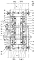
- Fig. 1 eine Vorrichtung gemäß der Erfindung im Längsschnitt und
- Fig. 2 eine Draufsicht zu Fig. 1 zeigt.
- Fig. 1 shows a device according to the invention in longitudinal section and
- Fig. 2 shows a top view of Fig. 1.
Die in der Zeichnung dargestellte Vorrichtung hat eine Einlaufseite (Pfeil E) für nacheinander zugeführte, je um eine Akkumulatorenplatte gefaltete, an den Seiten und hinten offene Separatorentaschen S, z.B. aus einer Polyethylenfolie (wobei die Falteinrichtung und die Einrichtung zum Zuführen der Akkumulatorenplatten nicht gezeigt sind), sowie eine Auslaufseite (Pfeil A) für die verschweißten Separatorentaschen S.The device shown in the drawing has an inlet side (arrow E) for separator pockets S which are fed one after the other and are each folded around an accumulator plate and open on the sides and rear, e.g. from a polyethylene film (the folding device and the device for feeding the battery plates are not shown), and an outlet side (arrow A) for the welded separator pockets S.
Die Vorrichtung weist zwei bezüglich einer Vertikalmittelebene V im wesentlichen symmetrische Hälften auf. Seitenteile 1 eines Rahmengestells, in denen alle wesentlichen Vorrichtungskomponenten gelagert sind, sind über mehrere Querteile 1' miteinander verbunden. Jeder Seitenteil 1 trägt oberhalb einer horizontalen Vorschubebene H einen einlaufseitigen Satz C und einen auslaufseitigen Satz D aus je drei, in einem Seitenschild 2 bzw. 2' gelagerten Zahnriemenrädern 3, 3', 3'', um die ein endloser oberer, als Zahnriemen 4 ausgebildeter Transportriemen geschlungen ist, der in Transportrichtung F der Separatorentaschen S umläuft. Das Zahnriemenrad 3 des auslaufseitigen Satzes D sitzt auf einer Antriebswelle M eines nicht gezeigten Motors.The device has two halves which are substantially symmetrical with respect to a vertical center plane
Unterhalb des einlaufseitigen Satzes C und des auslaufseitigen Satzes D von Zahnriemenrädern 3, 3', 3'' ist im Seitenschild 2 bzw. 2' je ein unteres Zahnriemenrad 5 bzw. 5' gelagert, wobei das Rad 5' ebenfalls auf einer Antriebswelle M sitxt. Um die Zahnriemenräder sowie um später erläuterte weitere Zahnriemenräder 6 und eine Spannrolle 7 ist ein unterer, ebenfalls als Zahnriemen 8 ausgebildeter Transportriemen geschlungen, der gemeinsam mit dem oberen Zahnriemen 4 eine an den zu verschweißenden Seitenteilen der Separatorentaschen S angreifende Transporteinrichtung bildet. Die beiden Zahnriemen 4, 8 sind synchron über die Zahnriemenräder 3, 5' angetrieben und üben auf die zu verschweißenden Separatorentaschen eine kontinuierliche gleichbleibende Zugkraft in der Transportrichtung aus.Below the inlet-side set C and the outlet-side set D of
An den Seitenschilden 2, 2' jeder Rahmengestellseite ist eine die der Vorschubebene H bildende Horizontalauflage 9 für die Separatorentaschen S montiert, die eine Niederhalterleiste 10 für die Seitenteile der Separatorentaschen trägt, die gegen die Auflage 9 mittels zweier Federvorspannmechanismen 11 federnd vorgespannt ist und unter welcher das untere Trum des oberen Zahnriemens 4 läuft. Die Niederhalterleiste 10 fluchtet mit den Zahnriemenrädern 3, 3', 3'' und hat die Aufgabe, die zwischen den Zahnriemen 4, 8 erfaßten Seitenteile der Separatorentaschen mit einem mittels der Federn der Vorspannmechanismen 11 einstellbaren vorbestimmten Druck in gegenseitiger Anlage zu halten. Die über die Niederhalterleiste 10 überstehenden, zu verschweißenden Ränder der Separatorentaschen S werden durch je eine seitliche, außerhalb der Niederhalterleiste 10 angeordnete Ultraschall-Schweißeinrichtung U hindurchgezogen, die eine vertikale untere Sonotrode 12 und einen mit dieser zusammenwirkenden oberen Amboß 13 aufweist, der als kontinuierlich drehende Kreisscheibe ausgebildet und auf einer Achse mit dem anderen Amboß in den Seitenteilen 1 drehbar gelagert und über einen Antrieb U' angetrieben ist. Die Auflage 9 trägt an ihrer Unterseite in Transportrichtung vor und hinter der Schweißeinrichtung U die beiden Zahnräder 6, welche das untere Trum des Zahnriemens 8 führen.On the
Die Federvorspannmechanismen 11 der Niederhalterleiste 10 sind je durch einen von unten mittels einer Feder 11' belasteten, um einen Schwenkzapfen 11'' schwenkbaren Kipparm 11''' gebildet, wobei die Federvorspannung mittels einer Schraube 11Iv einstellbar ist.The
Die an der Einlaufseite E nacheinander einlaufenden, je mit einer Akkumulatorenplatte gefüllten Separatorentaschen S werden mit Hilfe der Zahnriemenpaare 4, 8 fortlaufend unter die beiden Niederhalterleisten 10 gezogen, die dabei federnd etwas angehoben werden und die Seitenteile der Separatorentasche mit dem eingestellten Druck beaufschlagen, und durchlaufen die Ultraschall-Schweißeinrichtungen U, die kontinuierlich arbeiten. Die verschweißten Separatorentaschen S durchlaufen dann vor dem auslaufseitigen Zahnriemensatz D Seitenschneideinrichtungen T, die je ein Paar von oberen und unteren Schneidrädern 14 auf einer in den Seitenteilen 1 gelagerten Achse mit Antrieb T' aufweisen, mit welchen die verschweißten Taschenseitenränder getrimmt werden. Nach dem Verlassen der Vorrichtung werden die dreiseitig geschlossenen Separatorentaschen von einem Austragförderer B aufgenommen.The separator pockets S that arrive one after the other on the inlet side E and are each filled with an accumulator plate are continuously pulled under the two hold-
Im Bereich jeder Seitenschneideinrichtung ist an einem mit der zugeordneten Auflage 8 verbundenen Träger 15 die Spannrolle 7 gelagert.In the area of each side cutting device, the
Die die Zahnriemenräder lagernden Seitenschilde 2, 2' des Rahmengestells 1, 1' sind symmetrisch zur Längsmittelebene der Vorrichtung relativ zueinander einstellbar, u.zw. mittels einer Breiteneinstelleinrichtung 16, die zwei gegenläufige Spindeln 17 aufweist, welche mit den Seitenschilden 2, 2' über an diesen befestigte Muttern 18 in Eingriff stehen und je mittels eines Handrades 19 betätigbar sind, um die Schilde 2, 2' samt den von diesen getragenen Komponenten, insbesondere die Zahnriemen 4, 8 der Breite der Vorrichtung genau auf die Breite der zu verschweißenden Separatorentaschen einstellen zu können.The
Wie Fig. 1 zeigt sind die Zahnriemenräder 3', 3'' in den zugeordneten Seitenschilden 2, 2' mittels eines Winkels um die Achse des oberen Zahnriemenrades 3'' pendelnd aufgehängt, um das Ein- und Auslaufen der Separatorentasche zu erleichtern.As shown in FIG. 1, the toothed belt wheels 3 ', 3''in the associated
Der jeweilige Schweißspalt der Ultraschall-Schweißeinrichtungen U ist durch Höhenverstellung der Sonotroden 12 einstellbar.The respective welding gap of the ultrasonic welding devices U can be adjusted by adjusting the height of the
Es versteht sich, daß das erläuterte Ausführungsbeispiel im Rahmen des allgemeinen Erfindungsgedankens verschiedentlich abgewandelt werden kann.It is understood that the illustrated embodiment can be modified in various ways within the scope of the general inventive concept.
Claims (4)
- Device for producing separator pockets for electrical accumulator plates, comprising a means for folding sections of a web of ultrasonically weldable plastic material around each accumulator plate and a means for conveying the filled separator pocket to ultrasonic welding units where the superimposed side edges of the separator pockets are welded together, characterised in that the conveying means has two synchronised endless conveyor belts (4, 8) arranged above and below a horizontal conveying plane (H) for the separator pockets (S) and symmetrically to a longitudinal centre plane of the device, the belt sections extending parallel to the conveying plane (H) jointly gripping side parts of the separator pockets (S) and pulling the superimposed side edges of the separator pockets projecting beyond the conveyor belts continuously through the ultrasonic welding units (U), the upper and lower conveyor belts (4, 8) being guided by means of belt pulleys in respective side shields (2 and 2') of a frame at the inlet end and at the outlet end, and the side shields (2, 2') of both sides of the frame (1, 1') being adjustably held on the frame by means of an adjusting means (15) for adjusting the width of the weld edge symmetrically to the longitudinal centre plane of the device.
- Device according to claim 1, characterised in that a holding-down bar (10) is provided above a support (9) forming the conveying plane (H) and secured to the side shields (2, 2') aligned with each pair of conveyor belts (4, 8), said holding-down bar extending in front of and behind each ultrasonic welding unit (U) in the conveying direction of the separator pockets (S) and being mounted on the support (9) so that it is spring-loaded relative thereto, its basic distance from the support being adjustable.
- Device according to claim 1 or claim 2, characterised in that respective cutting means (T) for trimming the separator pockets (S) are provided behind the ultrasonic welding units (U) in the conveying direction.
- Device according to one of claims 1 to 3, characterised in that a pair of upper synchronous belt pulleys (3', 3'') are arranged to oscillate in each side shield (2 and 2') at the inlet end and at the outlet end.
Applications Claiming Priority (3)
| Application Number | Priority Date | Filing Date | Title |
|---|---|---|---|
| AT186/93 | 1993-02-03 | ||
| AT0018693A AT401319B (en) | 1993-02-03 | 1993-02-03 | DEVICE FOR PRODUCING SEPARATOR BAGS FOR ELECTRIC ACCUMULATOR PANELS |
| PCT/AT1994/000004 WO1994017984A1 (en) | 1993-02-03 | 1994-01-21 | Device for producing separator pockets for electrical accumulator plates |
Publications (2)
| Publication Number | Publication Date |
|---|---|
| EP0682598A1 EP0682598A1 (en) | 1995-11-22 |
| EP0682598B1 true EP0682598B1 (en) | 1996-12-11 |
Family
ID=3483770
Family Applications (1)
| Application Number | Title | Priority Date | Filing Date |
|---|---|---|---|
| EP94904909A Expired - Lifetime EP0682598B1 (en) | 1993-02-03 | 1994-01-21 | Device for producing separator pockets for electrical accumulator plates |
Country Status (7)
| Country | Link |
|---|---|
| US (1) | US5672236A (en) |
| EP (1) | EP0682598B1 (en) |
| AT (2) | AT401319B (en) |
| AU (1) | AU5875394A (en) |
| DE (1) | DE59401269D1 (en) |
| ES (1) | ES2097635T3 (en) |
| WO (1) | WO1994017984A1 (en) |
Families Citing this family (3)
| Publication number | Priority date | Publication date | Assignee | Title |
|---|---|---|---|---|
| DE19712498C2 (en) * | 1997-03-25 | 1999-01-14 | Windmoeller & Hoelscher | Device for welding workpieces lying flat on top of each other using the ultrasonic welding process |
| US6120629A (en) * | 1997-08-15 | 2000-09-19 | Tyco International (Us) Inc. | Ultrasonic processing |
| US11517977B2 (en) * | 2017-09-15 | 2022-12-06 | Tech-Sonic, Inc. | Dual cam servo weld splicer |
Family Cites Families (11)
| Publication number | Priority date | Publication date | Assignee | Title |
|---|---|---|---|---|
| US3294616A (en) * | 1963-10-03 | 1966-12-27 | Branson Instr | Apparatus for sealing polymeric sheet material by ultrasonic energy |
| US3505136A (en) * | 1966-09-19 | 1970-04-07 | Union Special Machine Co | Method and apparatus for bonding thermoplastic sheet materials |
| US4026000A (en) * | 1976-07-15 | 1977-05-31 | Globe-Union Inc. | Apparatus for producing enveloped battery plates |
| US4436585A (en) * | 1978-01-23 | 1984-03-13 | General Electric Company | Methods for making connection insulators |
| US4263712A (en) * | 1978-12-07 | 1981-04-28 | Dale Products, Inc. | Battery plate wrapping machine and method |
| DE2932409A1 (en) * | 1979-08-09 | 1981-02-26 | Crompton Batteries Ltd | Automated sealing of battery plate borders with extruded foam - opt. using expanded polyethylene shaped by external profile wheels |
| US4407063A (en) * | 1981-04-03 | 1983-10-04 | Johnson Peter E | Method and apparatus for fabricating battery plate envelopes |
| US4605454A (en) * | 1982-09-01 | 1986-08-12 | Kimberly-Clark Corporation | Method of ultrasonically bonding nonwoven webs |
| US4747895A (en) * | 1986-08-20 | 1988-05-31 | American White Cross Laboratories, Inc. | Continuous ultrasonic perforating system and method |
| US5591298A (en) * | 1988-01-19 | 1997-01-07 | Kimberly-Clark Corporation | Machine for ultrasonic bonding |
| JPH01294412A (en) * | 1988-05-11 | 1989-11-28 | Seal Kogyo Kk | Method and apparatus for sealing bag opening |
-
1993
- 1993-02-03 AT AT0018693A patent/AT401319B/en not_active IP Right Cessation
-
1994
- 1994-01-21 DE DE59401269T patent/DE59401269D1/en not_active Expired - Fee Related
- 1994-01-21 AT AT94904909T patent/ATE146122T1/en not_active IP Right Cessation
- 1994-01-21 AU AU58753/94A patent/AU5875394A/en not_active Abandoned
- 1994-01-21 EP EP94904909A patent/EP0682598B1/en not_active Expired - Lifetime
- 1994-01-21 US US08/500,986 patent/US5672236A/en not_active Expired - Fee Related
- 1994-01-21 ES ES94904909T patent/ES2097635T3/en not_active Expired - Lifetime
- 1994-01-21 WO PCT/AT1994/000004 patent/WO1994017984A1/en active IP Right Grant
Also Published As
| Publication number | Publication date |
|---|---|
| AT401319B (en) | 1996-08-26 |
| AU5875394A (en) | 1994-08-29 |
| ATA18693A (en) | 1995-12-15 |
| US5672236A (en) | 1997-09-30 |
| ES2097635T3 (en) | 1997-04-01 |
| DE59401269D1 (en) | 1997-01-23 |
| WO1994017984A1 (en) | 1994-08-18 |
| ATE146122T1 (en) | 1996-12-15 |
| EP0682598A1 (en) | 1995-11-22 |
Similar Documents
| Publication | Publication Date | Title |
|---|---|---|
| DE1704146A1 (en) | Process for the production of bags that can be closed by means of a releasable closure device and a device for carrying out this process | |
| DE2918499A1 (en) | DEVICE FOR TURNING AN OBJECT | |
| DE2555081A1 (en) | DEVICE FOR INTERMITTING A ROW OF OBJECTS IN AN ENDLESS CHAIN AND FOR CONTINUOUS DEPLOYMENT OF THE OBJECTS | |
| CH642594A5 (en) | METHOD AND DEVICE FOR AUTOMATICALLY APPLYING STICKERS ON A CONTINUOUS RAILWAY. | |
| DE2122089C3 (en) | Device for packing similar cuboid objects | |
| DE1479627A1 (en) | Machine for treating a material web, for example by thermal welding and cutting, in particular for the production of bags | |
| EP0682598B1 (en) | Device for producing separator pockets for electrical accumulator plates | |
| EP0182384A1 (en) | Device for stacking flat objects, preferably bags made from a plastic web | |
| EP0824452B1 (en) | Forming, maintaining and tensioning a banding loop | |
| EP0863080B1 (en) | Bag forming, filling and sealing machine with at least two transversal sealing devices | |
| DE3119452A1 (en) | Method for continuously moving a multiplicity of successive documents, and apparatuses relating thereto | |
| EP0506645B1 (en) | Apparatus for fabrication of battery plate envelopes | |
| EP1164648A2 (en) | Apparatus for producing pockets for battery of accumulator plates | |
| DD248567A1 (en) | DEVICE FOR FLOWING FOLDING OF ARCES OR BZW. SHEET MATERIAL | |
| DE649758C (en) | Sheet delivery device on corner conveyor tables of folding machines | |
| EP0227763A1 (en) | Device for transverse sealing and cutting of a folded-sheet web | |
| DE19920255A1 (en) | Packaging machine | |
| DE2931187A1 (en) | Plastics bag making and stacking machine - has welding roller, perforator and removal wheel feeding composite web to stacking drum | |
| AT393659B (en) | Method and apparatus for the closing of bags consisting of plastic films | |
| DE1055555B (en) | Conveyor system on high-speed rotary presses for the folded sheets delivered by the folder of the press with devices for aligning and stacking the folded sheets | |
| DE2135271A1 (en) | DEVICE FOR THE TEMPORARY AND SPATIAL ORIENTATION OF A CONTINUOUS SEQUENCE OF FINISHED OR PARTIALLY FOLDED LETTERHOLES, CUTS OR DGL | |
| DE1290473B (en) | Device for manufacturing, filling and closing packages | |
| DE2812798A1 (en) | Bag opening mechanism with conveyor feed - has opposite belt sections to guide bags at inlet end and hinged spreader blades (NL 26.9.78) | |
| DE1779405C (en) | Device for welding the Seg ments of continuously moving along a guide track, enlarged front and rear sections having thermoplastic film cassettes in the ultrasonic welding process | |
| DE1010897B (en) | Conveyor device for transferring clay moldings and other conveyed material from one conveyor track to an adjacent one |
Legal Events
| Date | Code | Title | Description |
|---|---|---|---|
| PUAI | Public reference made under article 153(3) epc to a published international application that has entered the european phase |
Free format text: ORIGINAL CODE: 0009012 |
|
| 17P | Request for examination filed |
Effective date: 19950731 |
|
| AK | Designated contracting states |
Kind code of ref document: A1 Designated state(s): AT BE CH DE ES FR GB IT LI NL PT |
|
| GRAG | Despatch of communication of intention to grant |
Free format text: ORIGINAL CODE: EPIDOS AGRA |
|
| 17Q | First examination report despatched |
Effective date: 19960221 |
|
| GRAH | Despatch of communication of intention to grant a patent |
Free format text: ORIGINAL CODE: EPIDOS IGRA |
|
| GRAH | Despatch of communication of intention to grant a patent |
Free format text: ORIGINAL CODE: EPIDOS IGRA |
|
| GRAA | (expected) grant |
Free format text: ORIGINAL CODE: 0009210 |
|
| AK | Designated contracting states |
Kind code of ref document: B1 Designated state(s): AT BE CH DE ES FR GB IT LI NL PT |
|
| PG25 | Lapsed in a contracting state [announced via postgrant information from national office to epo] |
Ref country code: NL Free format text: LAPSE BECAUSE OF FAILURE TO SUBMIT A TRANSLATION OF THE DESCRIPTION OR TO PAY THE FEE WITHIN THE PRESCRIBED TIME-LIMIT Effective date: 19961211 |
|
| REF | Corresponds to: |
Ref document number: 146122 Country of ref document: AT Date of ref document: 19961215 Kind code of ref document: T |
|
| REF | Corresponds to: |
Ref document number: 59401269 Country of ref document: DE Date of ref document: 19970123 |
|
| PG25 | Lapsed in a contracting state [announced via postgrant information from national office to epo] |
Ref country code: LI Effective date: 19970131 Ref country code: CH Effective date: 19970131 Ref country code: BE Effective date: 19970131 |
|
| PGFP | Annual fee paid to national office [announced via postgrant information from national office to epo] |
Ref country code: FR Payment date: 19970131 Year of fee payment: 4 Ref country code: ES Payment date: 19970131 Year of fee payment: 4 |
|
| PGFP | Annual fee paid to national office [announced via postgrant information from national office to epo] |
Ref country code: DE Payment date: 19970207 Year of fee payment: 4 |
|
| ITF | It: translation for a ep patent filed |
Owner name: MODIANO & ASSOCIATI S.R.L. |
|
| PGFP | Annual fee paid to national office [announced via postgrant information from national office to epo] |
Ref country code: AT Payment date: 19970227 Year of fee payment: 4 |
|
| PG25 | Lapsed in a contracting state [announced via postgrant information from national office to epo] |
Ref country code: PT Effective date: 19970311 |
|
| ET | Fr: translation filed | ||
| REG | Reference to a national code |
Ref country code: ES Ref legal event code: FG2A Ref document number: 2097635 Country of ref document: ES Kind code of ref document: T3 |
|
| GBT | Gb: translation of ep patent filed (gb section 77(6)(a)/1977) |
Effective date: 19970307 |
|
| NLV1 | Nl: lapsed or annulled due to failure to fulfill the requirements of art. 29p and 29m of the patents act | ||
| REG | Reference to a national code |
Ref country code: CH Ref legal event code: PL |
|
| PLBE | No opposition filed within time limit |
Free format text: ORIGINAL CODE: 0009261 |
|
| STAA | Information on the status of an ep patent application or granted ep patent |
Free format text: STATUS: NO OPPOSITION FILED WITHIN TIME LIMIT |
|
| 26N | No opposition filed | ||
| PG25 | Lapsed in a contracting state [announced via postgrant information from national office to epo] |
Ref country code: GB Free format text: LAPSE BECAUSE OF NON-PAYMENT OF DUE FEES Effective date: 19980121 Ref country code: AT Free format text: LAPSE BECAUSE OF NON-PAYMENT OF DUE FEES Effective date: 19980121 |
|
| PG25 | Lapsed in a contracting state [announced via postgrant information from national office to epo] |
Ref country code: ES Free format text: LAPSE BECAUSE OF EXPIRATION OF PROTECTION Effective date: 19980122 |
|
| PG25 | Lapsed in a contracting state [announced via postgrant information from national office to epo] |
Ref country code: FR Free format text: THE PATENT HAS BEEN ANNULLED BY A DECISION OF A NATIONAL AUTHORITY Effective date: 19980131 |
|
| GBPC | Gb: european patent ceased through non-payment of renewal fee |
Effective date: 19980121 |
|
| PG25 | Lapsed in a contracting state [announced via postgrant information from national office to epo] |
Ref country code: DE Free format text: LAPSE BECAUSE OF NON-PAYMENT OF DUE FEES Effective date: 19981001 |
|
| REG | Reference to a national code |
Ref country code: FR Ref legal event code: ST |
|
| REG | Reference to a national code |
Ref country code: ES Ref legal event code: FD2A Effective date: 20000601 |
|
| PG25 | Lapsed in a contracting state [announced via postgrant information from national office to epo] |
Ref country code: IT Free format text: LAPSE BECAUSE OF NON-PAYMENT OF DUE FEES Effective date: 20050121 |