EP0681616B1 - Cylindrical magnetron shield structure - Google Patents
Cylindrical magnetron shield structure Download PDFInfo
- Publication number
- EP0681616B1 EP0681616B1 EP94908576A EP94908576A EP0681616B1 EP 0681616 B1 EP0681616 B1 EP 0681616B1 EP 94908576 A EP94908576 A EP 94908576A EP 94908576 A EP94908576 A EP 94908576A EP 0681616 B1 EP0681616 B1 EP 0681616B1
- Authority
- EP
- European Patent Office
- Prior art keywords
- sputtering
- magnetic field
- shield
- target
- field zone
- Prior art date
- Legal status (The legal status is an assumption and is not a legal conclusion. Google has not performed a legal analysis and makes no representation as to the accuracy of the status listed.)
- Expired - Lifetime
Links
- 238000004544 sputter deposition Methods 0.000 claims abstract description 73
- 239000000463 material Substances 0.000 claims abstract description 31
- 238000009833 condensation Methods 0.000 claims description 16
- 230000005494 condensation Effects 0.000 claims description 16
- 238000005530 etching Methods 0.000 claims description 5
- 238000000034 method Methods 0.000 abstract description 8
- 238000007493 shaping process Methods 0.000 abstract description 3
- 238000005477 sputtering target Methods 0.000 description 22
- 239000000758 substrate Substances 0.000 description 15
- 238000000151 deposition Methods 0.000 description 13
- 230000008021 deposition Effects 0.000 description 12
- 238000004140 cleaning Methods 0.000 description 8
- 238000000429 assembly Methods 0.000 description 6
- 230000000712 assembly Effects 0.000 description 6
- 239000002826 coolant Substances 0.000 description 5
- 230000006872 improvement Effects 0.000 description 5
- 230000008901 benefit Effects 0.000 description 4
- 239000003989 dielectric material Substances 0.000 description 4
- 230000000694 effects Effects 0.000 description 4
- 239000007789 gas Substances 0.000 description 4
- 238000000992 sputter etching Methods 0.000 description 4
- VYPSYNLAJGMNEJ-UHFFFAOYSA-N Silicium dioxide Chemical compound O=[Si]=O VYPSYNLAJGMNEJ-UHFFFAOYSA-N 0.000 description 2
- 230000009286 beneficial effect Effects 0.000 description 2
- 230000015572 biosynthetic process Effects 0.000 description 2
- 239000011248 coating agent Substances 0.000 description 2
- 238000000576 coating method Methods 0.000 description 2
- 238000001816 cooling Methods 0.000 description 2
- 239000011521 glass Substances 0.000 description 2
- 150000002500 ions Chemical class 0.000 description 2
- 229910052751 metal Inorganic materials 0.000 description 2
- 239000002184 metal Substances 0.000 description 2
- 230000008569 process Effects 0.000 description 2
- 230000009471 action Effects 0.000 description 1
- 229910052782 aluminium Inorganic materials 0.000 description 1
- XAGFODPZIPBFFR-UHFFFAOYSA-N aluminium Chemical compound [Al] XAGFODPZIPBFFR-UHFFFAOYSA-N 0.000 description 1
- QVGXLLKOCUKJST-UHFFFAOYSA-N atomic oxygen Chemical compound [O] QVGXLLKOCUKJST-UHFFFAOYSA-N 0.000 description 1
- 230000000903 blocking effect Effects 0.000 description 1
- 238000010924 continuous production Methods 0.000 description 1
- 239000000110 cooling liquid Substances 0.000 description 1
- 238000009826 distribution Methods 0.000 description 1
- 230000009977 dual effect Effects 0.000 description 1
- 238000001914 filtration Methods 0.000 description 1
- 239000011810 insulating material Substances 0.000 description 1
- 230000007246 mechanism Effects 0.000 description 1
- 239000001301 oxygen Substances 0.000 description 1
- 229910052760 oxygen Inorganic materials 0.000 description 1
- 239000002245 particle Substances 0.000 description 1
- 238000002294 plasma sputter deposition Methods 0.000 description 1
- 238000005086 pumping Methods 0.000 description 1
- 230000009467 reduction Effects 0.000 description 1
- 230000004044 response Effects 0.000 description 1
- 238000000926 separation method Methods 0.000 description 1
- 229910052710 silicon Inorganic materials 0.000 description 1
- 239000010703 silicon Substances 0.000 description 1
- 235000012239 silicon dioxide Nutrition 0.000 description 1
- 239000000377 silicon dioxide Substances 0.000 description 1
- 229910001220 stainless steel Inorganic materials 0.000 description 1
- 239000010935 stainless steel Substances 0.000 description 1
Images


Classifications
-
- H—ELECTRICITY
- H01—ELECTRIC ELEMENTS
- H01J—ELECTRIC DISCHARGE TUBES OR DISCHARGE LAMPS
- H01J37/00—Discharge tubes with provision for introducing objects or material to be exposed to the discharge, e.g. for the purpose of examination or processing thereof
- H01J37/32—Gas-filled discharge tubes
- H01J37/34—Gas-filled discharge tubes operating with cathodic sputtering
- H01J37/3411—Constructional aspects of the reactor
- H01J37/3441—Dark space shields
-
- C—CHEMISTRY; METALLURGY
- C23—COATING METALLIC MATERIAL; COATING MATERIAL WITH METALLIC MATERIAL; CHEMICAL SURFACE TREATMENT; DIFFUSION TREATMENT OF METALLIC MATERIAL; COATING BY VACUUM EVAPORATION, BY SPUTTERING, BY ION IMPLANTATION OR BY CHEMICAL VAPOUR DEPOSITION, IN GENERAL; INHIBITING CORROSION OF METALLIC MATERIAL OR INCRUSTATION IN GENERAL
- C23C—COATING METALLIC MATERIAL; COATING MATERIAL WITH METALLIC MATERIAL; SURFACE TREATMENT OF METALLIC MATERIAL BY DIFFUSION INTO THE SURFACE, BY CHEMICAL CONVERSION OR SUBSTITUTION; COATING BY VACUUM EVAPORATION, BY SPUTTERING, BY ION IMPLANTATION OR BY CHEMICAL VAPOUR DEPOSITION, IN GENERAL
- C23C14/00—Coating by vacuum evaporation, by sputtering or by ion implantation of the coating forming material
- C23C14/22—Coating by vacuum evaporation, by sputtering or by ion implantation of the coating forming material characterised by the process of coating
- C23C14/34—Sputtering
- C23C14/35—Sputtering by application of a magnetic field, e.g. magnetron sputtering
-
- H—ELECTRICITY
- H01—ELECTRIC ELEMENTS
- H01J—ELECTRIC DISCHARGE TUBES OR DISCHARGE LAMPS
- H01J37/00—Discharge tubes with provision for introducing objects or material to be exposed to the discharge, e.g. for the purpose of examination or processing thereof
- H01J37/32—Gas-filled discharge tubes
- H01J37/32431—Constructional details of the reactor
- H01J37/3266—Magnetic control means
- H01J37/32669—Particular magnets or magnet arrangements for controlling the discharge
-
- H—ELECTRICITY
- H01—ELECTRIC ELEMENTS
- H01J—ELECTRIC DISCHARGE TUBES OR DISCHARGE LAMPS
- H01J37/00—Discharge tubes with provision for introducing objects or material to be exposed to the discharge, e.g. for the purpose of examination or processing thereof
- H01J37/32—Gas-filled discharge tubes
- H01J37/34—Gas-filled discharge tubes operating with cathodic sputtering
- H01J37/3402—Gas-filled discharge tubes operating with cathodic sputtering using supplementary magnetic fields
- H01J37/3405—Magnetron sputtering
-
- H—ELECTRICITY
- H01—ELECTRIC ELEMENTS
- H01J—ELECTRIC DISCHARGE TUBES OR DISCHARGE LAMPS
- H01J37/00—Discharge tubes with provision for introducing objects or material to be exposed to the discharge, e.g. for the purpose of examination or processing thereof
- H01J37/32—Gas-filled discharge tubes
- H01J37/34—Gas-filled discharge tubes operating with cathodic sputtering
- H01J37/3411—Constructional aspects of the reactor
- H01J37/3414—Targets
- H01J37/3426—Material
-
- H—ELECTRICITY
- H01—ELECTRIC ELEMENTS
- H01J—ELECTRIC DISCHARGE TUBES OR DISCHARGE LAMPS
- H01J37/00—Discharge tubes with provision for introducing objects or material to be exposed to the discharge, e.g. for the purpose of examination or processing thereof
- H01J37/32—Gas-filled discharge tubes
- H01J37/34—Gas-filled discharge tubes operating with cathodic sputtering
- H01J37/3411—Constructional aspects of the reactor
- H01J37/3461—Means for shaping the magnetic field, e.g. magnetic shunts
Definitions
- This invention relates generally to magnetrons of a type using rotating cylindrical sputtering targets, and, more specifically, to structures and techniques for minimizing arcing in such magnetrons.
- Cylindrical magnetrons are becoming widely used for depositing films on substrates.
- An example is the deposition of a stack of dielectric and metal layers on a surface of a glass substrate for the purpose of filtering out a portion of solar energy from passing through the glass.
- a substrate is positioned within a vacuum chamber containing at least one, and usually two, rotating cylindrical targets containing sputtering material on an outer surface thereof. Both inert and reactive gases are generally introduced into the chamber.
- a voltage applied to the sputtering target with respect to either the vacuum chamber enclosure or a separate anode, creates a plasma that is localized along a sputtering zone of the target by stationary magnets positioned within the target. Material is sputtered off the target surface and onto the substrate by bombarding the target with electrons and ions of the plasma as it passes through the stationary sputtering zone.
- the magnets are usually of a permanent magnet type, arranged along a line within the rotating cylindrical target and held against rotation with the target.
- the sputtering zone is created by the magnets along substantially the entire length of the cylindrical sputtering target and extends only a small circumferential (radial) distance around it.
- the magnets are arranged so that the sputtering zone exists at the bottom of the cylindrical target, facing a substrate being coated directly beneath.
- the film is desired to take place only on the substrate, it is also deposited on other surfaces within the reactive chamber. This can create a problem in many situations, especially when certain dielectrics are being deposited as the film.
- the target surface is silicon or aluminum and the reactive gas is oxygen
- silicon dioxide is deposited on the target surface, surfaces of target supporting structures, and the like, as well as on the substrate that is intended to be coated.
- arcing to those surfaces can begin. Arcing is undesirable since it generates particles that contaminate the film being deposited on the substrate, and overloads the power supply that creates the plasma through an electrical connection with the sputtering target surface and the vacuum chamber walls or some other anode.
- An advantage of a rotating cylindrical sputtering target is that such a film deposited on the target is subjected to being sputtered away as the target surface passes through the sputtering zone, thus counteracting the undesirable film build-up. Despite this self-cleaning characteristic, however, undesirable arcing still occurs in rotary magnetrons under certain circumstances.
- a shaped cylindrical shield structure is provided around and spaced apart from at least a portion of the sputtering target outside of said sputtering zone.
- the shape of the cylindrical shield structure is designed to conform to the contours of the magnetic field zone, thereby maximizing sputter etching of the tube ends while minimizing deposition of condensate.
- the shield structure consists of separate cylindrical end shields positioned at opposite ends of the target structure and shaped at their respective inner edges adjacent to the magnetic field zone to conform to the outer contours of the "race-track" pattern of the magnetic field zone.
- the shield structure may also consist of a unified shield wherein these shaped cylindrical end shields are connected at the portions their respective inner edges lying outside the magnetic field zone by a cylindrically shaped structure, leaving a window opening in the shield structure adjacent to the magnetic field zone so that the target surface is bombarded by electrons and ions of the plasma as it is rotated through the sputtering zone.
- the cylindrical shield structure does not rotate with the cylindrical target.
- the cylindrical shield structure is also made rotatable so that its window may follow the sputtering zone to its new position.
- Such a shield structure has been found to be beneficial in three primary respects.
- the self-cleaning attribute of a rotating sputtering target generally does not extend to the far ends of the target cylinder since the sputtering zone controlled by the magnets within the cylinder does not extend completely to its ends.
- An abrupt termination of the permanent magnets within the target cylinder creates some discontinuities in the sputtering zone at the ends of the cylinder, and thus in the character of the plasma itself.
- the shield structure of the present invention extends completely around the sputtering cylinder at its ends and, further, may be extended to cover portions of rotating target support structures adjacent to its ends which are particularly susceptible to undesirable film build-up because of their proximity to the sputtering surface and plasma.
- the shield structure of the present invention is similarly shaped to conform to the contours of the magnetic field zone, thereby shielding those areas at the ends of the target cylinder that would otherwise be exposed to condensate film build-up and subsequent arcing.
- a third beneficial aspect of the shield structure comes from covering a central portion of the length of the sputtering target cylinder, despite the self-cleaning attribute of a rotating magnetron mentioned above. It has been found that there are circumstances where an undesired dielectric or other film deposited on portions of the target outside of the sputtering zone are not completely removed when those surface portions again pass through the sputtering zone. Further, there are circumstances where it has been found desirable to be able to cover a portion of the cylindrical target surface during co-sputtering; that is, in a situation where two rotating cylindrical target structures are adjacent one another and material from at least one of them is being sputtered onto the surface of another before being resputtered onto a substrate. It is the ability to cover a portion of the target during such co-sputtering that is provided by the present invention.
- a box 11 shown in dotted outline, indicates metallic walls of a vacuum chamber in which the sputtering occurs.
- the target structures 13 and 15 are generally held with their axes parallel to one another, but that is not a requirement.
- two target structures are illustrated in Figure 1, many applications need only employ one such target, and other applications can benefit by having more than two. However, the use of two target structures 13 and 15 is common.
- the magnetron of Figure 1 is shown to have a substrate 17 held by a support structure 19.
- the support structure 19 may be rollers to allow the substrate 17 to be passed through the vacuum chamber in a continuous process.
- a vacuum is drawn within the vacuum chamber by an appropriate pumping system 21.
- One or more gases are provided by a supply 23 to the vacuum chamber by some convenient delivery system, such as a perforated tube 25 positioned across the vacuum chamber. The particular gases utilized depend primarily upon the film desired to be deposited on the substrate 17.
- Cylindrical pieces 27 and 29 of sputtering material provided as part of the target structures 13 and 15, respectively, are generally made of the same material but can be of different materials, depending upon the nature of the film to be deposited on the substrate 17.
- An electric motor source 31 positioned outside the vacuum chamber, rotates the target assemblies by rotating, through a toothed belt 33, pulleys 35 and 37 which are attached to respective spindles 39 and 41.
- the sputtering materials 27 and 29 are attached to the respective spindles 39 and 41 in order to rotate with them.
- a plasma is created within the vacuum chamber by applying a negative voltage from a power supply 40 to the sputtering surfaces with respect to the vacuum chamber metal frame 11 or some other anode, which is usually connected to ground potential.
- the plasma is positioned adjacent a sputtering zone of the cylindrical sputtering targets 27 and 29, controlled by the positioning of their respective magnets (not shown in Figure 1). These magnets are positioned along the length of their respective cylindrical sputtering targets 27 and 29, while extending a small circumferential, or radial, distance therearound. These magnets are most conveniently held within the sputtering targets 27 and 29 by attachment to respective coolant conduits 43 and 45. These cooling conduits are provided as part of their respective target assemblies in a manner to be rotatable independently of rotation of their respective cylindrical sputtering targets 27 and 29.
- a pulley 47 is attached to the conduit 43 and driven from an electrical motor source 49 outside the vacuum chamber by a toothed belt 51.
- a pulley 53 is attached to the coolant conduit 45 and is controlled as to rotatable position by an electrical motor source 55 positioned outside the vacuum chamber and connected with it by a toothed belt 57.
- the motor sources 49 and 55 are preferably stepper motors which thereby hold their respective conduits 43 and 45 in selected positions and keep them from rotating with their respective sputtering targets 27 and 29.
- a cooling liquid supply and exhaust system (not shown) outside the vacuum chamber provides coolant into the center of each of the conduits 43 and 45, as indicated by an arrow 61, and exhausts the heated coolant from a space between the outside of the conduits and an interior surface of the spindles, as indicated by an arrow 63.
- An electrical and electronic control system 59 operates to control the power supply 40 and various parameters of the magnetron system being shown, including motors 31, 49 and 55.
- the improvement of the present invention is implemented in the system of Figure 1 by providing cylindrically-shaped shield structures 67 and 69, or blocking means, around and spaced from each of the cylindrical target surfaces 27 and 29, respectively. Additionally, the cylinders extend in length beyond the end of the sputtering material in order to cover exposed surfaces of adjacent spindles and their supporting structures. Window openings 72 and 74, adjacent to respective shield structures 67 and 69, are large enough to expose the sputtering zone. These areas do not extend the full length of the cylindrical shield structures 67 and 69, however, leaving covered completely around their circumferences the respective sputtering surfaces 27 and 29 for a distance immediately adjacent the opposite ends of the sputtering material cylinder.
- the shield structures 67 and 69 are then most easily held with their windows in a fixed position.
- the magnets are made to be rotatable, as described in the embodiment of Figure 1, such as is useful in the co-sputtering application previously mentioned, it is desirable to be able to controllably rotate the shield structures 67 and 69 so that their respective openings 72 and 74 follow the moving sputtering zone.
- the extent of shield structure rotation is made to be at least as great as the extent of magnet rotation. This allows the radial extent of the openings 72 and 74 to be kept small and thus maximize the coverage of the sputtering surface outside th sputtering zone.
- the shield structure 67 is provided with a pulley 71 around its circumference near one end, and the shield structure 69 is similarly provided with a pulley 73.
- An electrical motor source 75 rotates the shield structure 67 through a toothed belt 79, and a motor source 77 rotates the shield 69 through a toothed belt 81.
- the motor sources 75 and 77 are preferably stepper motors and are also controlled by connection with the control system 59.
- Elongated magnets 85, 87 and 89 are carried within the sputtering material cylinder 29 by a support structure 91 that is attached to the coolant tube 45.
- the sputtering tube 29 and the shield structure 69 are independently rotatable about a longitudinal axis 93 by respective motor sources 55, 31 and 77.
- shield structure 69 of Figure 2 is shaped at portions of its inner edges 70 that are adjacent to window openings 72 and 74 to conform to the contours of the magnetic field zone.
- the shape of the shield structure 69 is shown in Figure 2, while the method of designing the shape of the shield structure is fully described below in relation to Figure 6.
- the contoured shape of the shield structure 69 at inner edges 70 maximizes the self-cleaning characteristic of rotary cylindrical magnetrons according to a "race-track" pattern of etching, while minimizing the formation of condensate at the end portions of a cylindrical sputtering target assembly.
- a most important aspect of the invention is the shaping of the shield structure to minimize undesirable condensation of materials vaporized during the sputtering process, particularly dielectrics, and thereby reduce the often catastrophic arcing that results.
- FIG. 3 An alternative embodiment of the present invention is shown in Figure 3. Similar to the embodiment illustrated in Figure 2 comprised of shield structure 69, this alternative embodiment includes separate shield structures 69A and 69B positioned around and spaced from the target surface 29. Shield structures 69A and 69B are positioned at opposite ends of the target assembly 15 and are provided with pulleys 73A and 73B around their respective circumferences to be independently rotatable. According to the present invention, shield structures 69A and 69B are shaped at portions of their respective inner edges 70A and 70B that are adjacent to the opening 29 to conform to the contours of the magnetic field zone. It will be understood that the magnetron system, the magnetic assembly, the independent rotation, the supporting structure, and the shaping features of the invention described herein are adapted to be equally applicable in the embodiment shown in Figure 3.
- a specific supporting structure for a target assembly is given.
- a cylindrical sputtering surface 95 is carried through end spindles 97 and 99 in a manner to be rotatable about a longitudinal axis 101.
- a magnetic structure 103 is positioned within the target cylinder 95.
- plates 105 and 107 are provided at opposite ends of the target assembly. These end plates carry respective annular grooves 109 and 111 into which a cylindrically-shaped shield structure 113 is inserted at its ends. The shield structure 113 is then easily rotatable by a motor source connected to a pulley 115.
- This support arrangement for the shield structure 113 also has an advantage of covering portions of the end plates 105 and 107 that are immediately adjacent ends of the sputtering target cylinder 95. These supporting structure surfaces are particularly susceptible to deposition of undesirable films on them, because of their proximity to the plasma sputtering zone, so are very useful for this purpose. Additionally, as previously mentioned, end portions 117 and 119 are circumferentially continuous around the shield structure and extend far enough along its length to cover respective end portions of the sputtering target 95 where the self-cleaning action of a rotating target acts as effectively as it does in more central portions of the target's length. A window 121 is provided, however, in the shield 113 to expose at least the sputtering zone.
- the shield structure 113 is preferably made of a material that itself has a low sputtering yield, such as stainless steel.
- cylindrical magnetron shield structures Prior to this invention, the design of cylindrical magnetron shield structures was based on the observation of the target structures after they had undergone sputter etching in a rotary cylindrical magnetron in which the target structures were rotated. Because the target structures were rotated, the. sputtering surface was observed as a uniformly etched surface with a band of deposited material at the ends of the target structure. Based on this observation, rotary cylindrical magnetrons were thought to avoid the problem of "race-track" etching of the sputtering surface, as observed in planar magnetrons with a fixed sputtering zone. See Kirs, Milan R., et al., "Cylindrical Magnetron Shield Structrure," U.S. Patent No. 5,108,574. Consequently, shield structures for such rotary cylindrical magnetrons were designed with rectangularly-shaped inner edges adjacent to the sputtering zone to shield the area at the ends of the target structure corresponding to the observed condensation band.
- sputtering surfaces of rotary cylindrical magnetrons are indeed etched in a well-defined "race-track” pattern, causing condensate build-up in a conforming pattern at the ends of the target structure.
- a cylindrical sputtering target 131 is shown after it has undergone sputter etching in a rotary cylindrical magnetron in which the target structures are held immobile.
- a "race-track" pattern on the sputtering surface bounded by boundary 139 indicates the area of the target surface lying between the region of maximum magnetic field strength 135 and boundary 139 that has been etched during the sputter etching process.
- Areas 143, 145, 147, and 149 on the sputtering surfrace, which conform to the "race-track" etch pattern, indicate the pattern of condensation at the end portions of the sputtering target. Such condensation occurs at positions on the sputtering surface where the rate of condensation exceeds the rate at which deposited condensate is removed by sputtering.
- magnetic paper is positioned on the target surface during operation of the rotating cylindrical magnetron.
- Magnetic paper is commercially available from a number of sources, including Edmund Scientific Company of New Jersey.
- the magnetic paper is marked by isomagnetic lines indicating the configuration of the magnetic field zone.
- the shield structure is then shaped at its inner edges adjacent to the magnetic field zone to conform to the contours of the magnetic field zone, as indicated by the isomagnetic lines.
- the resulting design takes the form of a curved, notched shape at the inner edges of the shield structure, as illustrated in Figures 2 and 3.
- the cylindrically-shaped shield structure is designed according to the patterns of condensation and etching that are observable on the target structure after the rotary cylindrical magnetron has been operated with the target structure held stationary.
- the inner edges 70 in Figure 2 and 70A and 70B in Figure 3 of the shield structure are designed in a curved, notched shape that follows the contours of the areas of condensation 143, 145, 147 and 149 in Figure 6 appearing on the target surface.
- the inner edges may be designed in a curved, notched shape that follows the contours of the "race-track" etch pattern 139 in Figure 6 as it appears at the ends of the target structure.
- the shield structure of the present invention is positioned on the target ends, a fixed distance from the magnetic field zone.
- arcing activity is monitored using a strip chart recorder that is connected to power supply 40 of Figure 1.
- the recorder is used to record any reduction in voltage that occurs over time in response to arcing activity, with fewer voltage drops indicating less arcing activity in the magnetron system.
- This sequence is repeated with the shaped inner edges of the shield structure positioned at various distances from the magnetic field zone, until the optimum distance from the magnetic field zone is determined.
- the shield structure is extended lengthwise toward the magnetic field zone such that the inner edges of the shield and the magnetic field zone are separated by this optimum distance.
- the shield structure of the present invention provides for maximum self-cleaning in the sputtering zone and minimum condensation beyond the sputtering zone and thereby reduces arcing activity in a rotary cylindrical magnetron.
Landscapes
- Chemical & Material Sciences (AREA)
- Engineering & Computer Science (AREA)
- Physics & Mathematics (AREA)
- Plasma & Fusion (AREA)
- Analytical Chemistry (AREA)
- Metallurgy (AREA)
- Materials Engineering (AREA)
- Mechanical Engineering (AREA)
- Chemical Kinetics & Catalysis (AREA)
- Organic Chemistry (AREA)
- Physical Vapour Deposition (AREA)
- Discharge Lamps And Accessories Thereof (AREA)
- Microwave Tubes (AREA)
- Constitution Of High-Frequency Heating (AREA)
- Earth Drilling (AREA)
- Surgical Instruments (AREA)
- Acyclic And Carbocyclic Compounds In Medicinal Compositions (AREA)
Abstract
Description
- This invention relates generally to magnetrons of a type using rotating cylindrical sputtering targets, and, more specifically, to structures and techniques for minimizing arcing in such magnetrons.
- Cylindrical magnetrons are becoming widely used for depositing films on substrates. An example is the deposition of a stack of dielectric and metal layers on a surface of a glass substrate for the purpose of filtering out a portion of solar energy from passing through the glass. Such a substrate is positioned within a vacuum chamber containing at least one, and usually two, rotating cylindrical targets containing sputtering material on an outer surface thereof. Both inert and reactive gases are generally introduced into the chamber. A voltage applied to the sputtering target, with respect to either the vacuum chamber enclosure or a separate anode, creates a plasma that is localized along a sputtering zone of the target by stationary magnets positioned within the target. Material is sputtered off the target surface and onto the substrate by bombarding the target with electrons and ions of the plasma as it passes through the stationary sputtering zone.
- The magnets are usually of a permanent magnet type, arranged along a line within the rotating cylindrical target and held against rotation with the target. The sputtering zone is created by the magnets along substantially the entire length of the cylindrical sputtering target and extends only a small circumferential (radial) distance around it. Traditionally, the magnets are arranged so that the sputtering zone exists at the bottom of the cylindrical target, facing a substrate being coated directly beneath.
- Although deposition of the film is desired to take place only on the substrate, it is also deposited on other surfaces within the reactive chamber. This can create a problem in many situations, especially when certain dielectrics are being deposited as the film. For example, if the target surface is silicon or aluminum and the reactive gas is oxygen, silicon dioxide is deposited on the target surface, surfaces of target supporting structures, and the like, as well as on the substrate that is intended to be coated. After a certain build-up of dielectric material on internal vacuum chamber surfaces has occurred over time, arcing to those surfaces can begin. Arcing is undesirable since it generates particles that contaminate the film being deposited on the substrate, and overloads the power supply that creates the plasma through an electrical connection with the sputtering target surface and the vacuum chamber walls or some other anode.
- An advantage of a rotating cylindrical sputtering target is that such a film deposited on the target is subjected to being sputtered away as the target surface passes through the sputtering zone, thus counteracting the undesirable film build-up. Despite this self-cleaning characteristic, however, undesirable arcing still occurs in rotary magnetrons under certain circumstances.
- Recently, a cylindrical' magnetron shield structure has been developed to minimize this undesirable arcing that occurs in rotary cylindrical magnetrons. See Kirs, Milan R., et al., "Cylindrical Magnetron Shield Structure, "U.S. Patent No. 5,108,574. As shown in Kirs et al., the deposition of dielectric film can be minimized by dark space shielding, which prevents plasma formation in the dark space and thereby reduces film deposition and subsequent arcing.
- Although the shield structure of Kirs et al. greatly enhances the self-cleaning characteristic of rotary cylindrical magnetrons, some deposition of condensate has been found to occur at the far ends of the target cylinder. Unlike the deposition of dielectric films that concerned Kirs et al., this deposition of condensate from the vapor present in the system occurs regardless of the existence of plasma. Thus, the problem of condensate deposition is not fully resolved by the use of dark space shielding.
- Because even slight deposition of dielectric or insulating materials can lead to undesirable arcing, it is a principal object of the present invention to provide a mechanism and technique for further minimizing such deposition and related arching.
- This and additional objects are accomplished by the present invention which provides a sputtering apparatus comprising:
- a magnetron having a vacuum chamber including therein at least one target structure with an outer cylindrically-shaped surface of sputtering material;
- first and second support structures holding the target structure at opposite ends thereof such that the target structure is rotatable about its longitudinal axis;
- a magnet assembly within the target structure that provides a magnetic field zone extending along a length of the sputtering material surface and extending a circumferential distance therearound; and
- first and second cylindrical shields, the shields carried at opposite ends of the target structure by the first and second support structures and extended axially along the sputtering material surface to substantially cover the ends of the sputtering material surface, the first shield having an inner edge closest to the second shield and the second shield having an inner edge closest to the first shield, characterised in that the inner edges adjacent to the magnetic field zone are shaped to conform substantially to the contours of the magnetic field zone, are non-rectangularly shaped to conform substantially to a shape of a pattern of condensation of vaporised material on the target structure formed when the target structure is held stationary, and in that the inner edges are positioned to shield regions in which condensation of vaporised material on the target structures would otherwise occur at a rate which exceeds a rate at which deposited condensate is removed from the target structure by sputtering.
-
- Briefly and generally in accordance with the invention, a shaped cylindrical shield structure is provided around and spaced apart from at least a portion of the sputtering target outside of said sputtering zone. By careful examination of the shape of the magnetic field zone and the distribution of the condensate at the ends of the tube, the shape of the cylindrical shield structure is designed to conform to the contours of the magnetic field zone, thereby maximizing sputter etching of the tube ends while minimizing deposition of condensate. The shield structure consists of separate cylindrical end shields positioned at opposite ends of the target structure and shaped at their respective inner edges adjacent to the magnetic field zone to conform to the outer contours of the "race-track" pattern of the magnetic field zone. The shield structure may also consist of a unified shield wherein these shaped cylindrical end shields are connected at the portions their respective inner edges lying outside the magnetic field zone by a cylindrically shaped structure, leaving a window opening in the shield structure adjacent to the magnetic field zone so that the target surface is bombarded by electrons and ions of the plasma as it is rotated through the sputtering zone. The cylindrical shield structure does not rotate with the cylindrical target. In systems that provide for the sputtering zone to be circumferentially positionable around the target by rotation of its magnets, the cylindrical shield structure is also made rotatable so that its window may follow the sputtering zone to its new position.
- Such a shield structure has been found to be beneficial in three primary respects. First, it has been found that the self-cleaning attribute of a rotating sputtering target generally does not extend to the far ends of the target cylinder since the sputtering zone controlled by the magnets within the cylinder does not extend completely to its ends. An abrupt termination of the permanent magnets within the target cylinder creates some discontinuities in the sputtering zone at the ends of the cylinder, and thus in the character of the plasma itself. Since the self-cleaning attribute of a rotating target does not fully extend to the ends of the target cylinder, the shield structure of the present invention extends completely around the sputtering cylinder at its ends and, further, may be extended to cover portions of rotating target support structures adjacent to its ends which are particularly susceptible to undesirable film build-up because of their proximity to the sputtering surface and plasma.
- Additionally, it has been found that much like planar magnetrons, rotary cylindrical magnetrons etch the sputtering surface in a "race-track" pattern, while causing a build-up of arc-causing condensate film at the ends of the target cylinder in a pattern that conforms to the shape of the "race-track." Since this undesirable condensate film conforms to the "race-track" shape of the magnetic field zone, the shield structure of the present invention is similarly shaped to conform to the contours of the magnetic field zone, thereby shielding those areas at the ends of the target cylinder that would otherwise be exposed to condensate film build-up and subsequent arcing.
- A third beneficial aspect of the shield structure comes from covering a central portion of the length of the sputtering target cylinder, despite the self-cleaning attribute of a rotating magnetron mentioned above. It has been found that there are circumstances where an undesired dielectric or other film deposited on portions of the target outside of the sputtering zone are not completely removed when those surface portions again pass through the sputtering zone. Further, there are circumstances where it has been found desirable to be able to cover a portion of the cylindrical target surface during co-sputtering; that is, in a situation where two rotating cylindrical target structures are adjacent one another and material from at least one of them is being sputtered onto the surface of another before being resputtered onto a substrate. It is the ability to cover a portion of the target during such co-sputtering that is provided by the present invention.
- Additional objects, features and advantages of the present invention will become apparent from the following description of a preferred embodiment thereof, which description should be taken in conjunction with the accompanying drawings.
-
- Figure 1 schematically illustrates a dual cylindrical sputtering target magnetron that utilizes the improvement of the present invention;
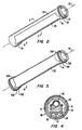
- Figure 2 shows in isometric view a portion of one of the target assemblies of Figure 1, including the improvement of the present invention;
- Figure 3 shows in isometric view a portion of one of the target assemblies of Figure 1, including the improvement of the present invention;
- Figure 4 is a cross-section of a target assembly taken at Section 4-4 of Figure 2;
- Figure 5 is a partial section view of a preferred support assembly for a rotating target assembly of the types illustrated in Figures 1-5; and
- Figure 6 shows in isometric view a "race-track" pattern of etching and a conforming pattern of condensation at the end portions of a cylindrical sputtering target assembly of Figure 1 that are used in designing the improvement of the present invention.
-
- Referring initially to Figure 1, an entire magnetron system utilizing the present invention is generally described before the details of the invention's preferred implementation are explained. A box 11, shown in dotted outline, indicates metallic walls of a vacuum chamber in which the sputtering occurs. Within that chamber are two rotatable
cylindrical target structures 13 and 15 which are held by the frame 11 in a manner to be rotatable about their longitudinal axes. Thetarget structures 13 and 15 are generally held with their axes parallel to one another, but that is not a requirement. Further, although two target structures are illustrated in Figure 1, many applications need only employ one such target, and other applications can benefit by having more than two. However, the use of twotarget structures 13 and 15 is common. - The magnetron of Figure 1 is shown to have a substrate 17 held by a
support structure 19. Thesupport structure 19 may be rollers to allow the substrate 17 to be passed through the vacuum chamber in a continuous process. A vacuum is drawn within the vacuum chamber by anappropriate pumping system 21. One or more gases are provided by a supply 23 to the vacuum chamber by some convenient delivery system, such as aperforated tube 25 positioned across the vacuum chamber. The particular gases utilized depend primarily upon the film desired to be deposited on the substrate 17. -
Cylindrical pieces target structures 13 and 15, respectively, are generally made of the same material but can be of different materials, depending upon the nature of the film to be deposited on the substrate 17. An electric motor source 31, positioned outside the vacuum chamber, rotates the target assemblies by rotating, through atoothed belt 33, pulleys 35 and 37 which are attached to respective spindles 39 and 41. The sputteringmaterials - A plasma is created within the vacuum chamber by applying a negative voltage from a
power supply 40 to the sputtering surfaces with respect to the vacuum chamber metal frame 11 or some other anode, which is usually connected to ground potential. The plasma is positioned adjacent a sputtering zone of the cylindrical sputtering targets 27 and 29, controlled by the positioning of their respective magnets (not shown in Figure 1). These magnets are positioned along the length of their respective cylindrical sputtering targets 27 and 29, while extending a small circumferential, or radial, distance therearound. These magnets are most conveniently held within the sputtering targets 27 and 29 by attachment torespective coolant conduits 43 and 45. These cooling conduits are provided as part of their respective target assemblies in a manner to be rotatable independently of rotation of their respective cylindrical sputtering targets 27 and 29. - Thus, the position of the magnets in each target assembly, and thus the position of the sputtering zone of each, is controlled by rotation of these cooling conduits. Specifically, a pulley 47 is attached to the conduit 43 and driven from an
electrical motor source 49 outside the vacuum chamber by a toothed belt 51. Similarly, a pulley 53 is attached to thecoolant conduit 45 and is controlled as to rotatable position by anelectrical motor source 55 positioned outside the vacuum chamber and connected with it by atoothed belt 57. The motor sources 49 and 55 are preferably stepper motors which thereby hold theirrespective conduits 43 and 45 in selected positions and keep them from rotating with their respective sputtering targets 27 and 29. - A cooling liquid supply and exhaust system (not shown) outside the vacuum chamber provides coolant into the center of each of the
conduits 43 and 45, as indicated by anarrow 61, and exhausts the heated coolant from a space between the outside of the conduits and an interior surface of the spindles, as indicated by an arrow 63. An electrical andelectronic control system 59 operates to control thepower supply 40 and various parameters of the magnetron system being shown, includingmotors - The improvement of the present invention is implemented in the system of Figure 1 by providing cylindrically-shaped
shield structures Window openings 72 and 74, adjacent torespective shield structures cylindrical shield structures - If the sputtering zone defining magnets inside the target assemblies are held fixed, the
shield structures shield structures respective openings 72 and 74 follow the moving sputtering zone. The extent of shield structure rotation is made to be at least as great as the extent of magnet rotation. This allows the radial extent of theopenings 72 and 74 to be kept small and thus maximize the coverage of the sputtering surface outside th sputtering zone. On the other hand, it is possible to make the radial extent of theopenings 72 and 74 very large, thus allowing a limited rotation of the magnets without having to rotate the shield structures. But maximum flexibility of operation is permitted, of course, when rotation of theshield structures - In order to accomplish such rotation, the
shield structure 67 is provided with a pulley 71 around its circumference near one end, and theshield structure 69 is similarly provided with apulley 73. An electrical motor source 75 rotates theshield structure 67 through atoothed belt 79, and amotor source 77 rotates theshield 69 through atoothed belt 81. The motor sources 75 and 77 are preferably stepper motors and are also controlled by connection with thecontrol system 59. - Additional details of the target assemblies shown in Figure 1 are apparent from the views of Figures 2 and 4 of the
target assembly 15.Elongated magnets material cylinder 29 by asupport structure 91 that is attached to thecoolant tube 45. In this magnetic assembly, the sputteringtube 29 and theshield structure 69 are independently rotatable about alongitudinal axis 93 byrespective motor sources - It will be noted from Figure 4 that a space exists between an outside surface of the
target cylinder 29 and an inside surface of the cylindrically-shapedshield tube 69. Both these surfaces are, in cross-section, concentric circles that are separated by a distance that is significantly less than one inch, preferably less than substantially one-quarter inch. A small separation is required in order to avoid plasma from forming in the space between these two elements. - According to the present invention,
shield structure 69 of Figure 2 is shaped at portions of itsinner edges 70 that are adjacent towindow openings 72 and 74 to conform to the contours of the magnetic field zone. The shape of theshield structure 69 is shown in Figure 2, while the method of designing the shape of the shield structure is fully described below in relation to Figure 6. The contoured shape of theshield structure 69 atinner edges 70 maximizes the self-cleaning characteristic of rotary cylindrical magnetrons according to a "race-track" pattern of etching, while minimizing the formation of condensate at the end portions of a cylindrical sputtering target assembly. A most important aspect of the invention is the shaping of the shield structure to minimize undesirable condensation of materials vaporized during the sputtering process, particularly dielectrics, and thereby reduce the often catastrophic arcing that results. - An alternative embodiment of the present invention is shown in Figure 3. Similar to the embodiment illustrated in Figure 2 comprised of
shield structure 69, this alternative embodiment includesseparate shield structures 69A and 69B positioned around and spaced from thetarget surface 29.Shield structures 69A and 69B are positioned at opposite ends of thetarget assembly 15 and are provided withpulleys 73A and 73B around their respective circumferences to be independently rotatable. According to the present invention,shield structures 69A and 69B are shaped at portions of their respectiveinner edges opening 29 to conform to the contours of the magnetic field zone. It will be understood that the magnetron system, the magnetic assembly, the independent rotation, the supporting structure, and the shaping features of the invention described herein are adapted to be equally applicable in the embodiment shown in Figure 3. - Referring to Figure 5, a specific supporting structure for a target assembly is given. A
cylindrical sputtering surface 95 is carried throughend spindles longitudinal axis 101. Amagnetic structure 103 is positioned within thetarget cylinder 95. As part of target supporting structures,plates annular grooves 109 and 111 into which a cylindrically-shapedshield structure 113 is inserted at its ends. Theshield structure 113 is then easily rotatable by a motor source connected to apulley 115. - This support arrangement for the
shield structure 113 also has an advantage of covering portions of theend plates sputtering target cylinder 95. These supporting structure surfaces are particularly susceptible to deposition of undesirable films on them, because of their proximity to the plasma sputtering zone, so are very useful for this purpose. Additionally, as previously mentioned,end portions sputtering target 95 where the self-cleaning action of a rotating target acts as effectively as it does in more central portions of the target's length. A window 121 is provided, however, in theshield 113 to expose at least the sputtering zone. Theshield structure 113 is preferably made of a material that itself has a low sputtering yield, such as stainless steel. - Prior to this invention, the design of cylindrical magnetron shield structures was based on the observation of the target structures after they had undergone sputter etching in a rotary cylindrical magnetron in which the target structures were rotated. Because the target structures were rotated, the. sputtering surface was observed as a uniformly etched surface with a band of deposited material at the ends of the target structure. Based on this observation, rotary cylindrical magnetrons were thought to avoid the problem of "race-track" etching of the sputtering surface, as observed in planar magnetrons with a fixed sputtering zone. See Kirs, Milan R., et al., "Cylindrical Magnetron Shield Structrure," U.S. Patent No. 5,108,574. Consequently, shield structures for such rotary cylindrical magnetrons were designed with rectangularly-shaped inner edges adjacent to the sputtering zone to shield the area at the ends of the target structure corresponding to the observed condensation band.
- It has been discovered, however, that the sputtering surfaces of rotary cylindrical magnetrons are indeed etched in a well-defined "race-track" pattern, causing condensate build-up in a conforming pattern at the ends of the target structure. Referring to Figure 6, a
cylindrical sputtering target 131 is shown after it has undergone sputter etching in a rotary cylindrical magnetron in which the target structures are held immobile. A "race-track" pattern on the sputtering surface bounded byboundary 139 indicates the area of the target surface lying between the region of maximummagnetic field strength 135 andboundary 139 that has been etched during the sputter etching process.Areas - When a sputtering target exposed to condensation is further examined, there is evidence of significant damage to the target structure attributable to catastrophic arcing. Additionally, an examination of the coated substrate reveals similar evidence of damage to the coating attributable to arcing. By contrast, when a sputtering target is shielded from condensation using the shaped shield structures of the present invention, arcing is minimized and dagmage to the target structure and the substrate coating is significantly reduced.
- In a preferred method of designing the cylindrically-shaped shield structure of the present invention, magnetic paper is positioned on the target surface during operation of the rotating cylindrical magnetron. Magnetic paper is commercially available from a number of sources, including Edmund Scientific Company of New Jersey. During operation, the magnetic paper is marked by isomagnetic lines indicating the configuration of the magnetic field zone. The shield structure is then shaped at its inner edges adjacent to the magnetic field zone to conform to the contours of the magnetic field zone, as indicated by the isomagnetic lines. In a preferred form, the resulting design takes the form of a curved, notched shape at the inner edges of the shield structure, as illustrated in Figures 2 and 3.
- Alternatively, the cylindrically-shaped shield structure is designed according to the patterns of condensation and etching that are observable on the target structure after the rotary cylindrical magnetron has been operated with the target structure held stationary. Referring to Figures 2, 3 and 6, the
inner edges 70 in Figure 2 and 70A and 70B in Figure 3 of the shield structure are designed in a curved, notched shape that follows the contours of the areas ofcondensation etch pattern 139 in Figure 6 as it appears at the ends of the target structure. - Once shaped, the inner edges of the shield structure are positioned at an optimum distance from the magnetic field zone so that condensation and subsequent arcing are minimized at the ends of the target without disturbing the plasma. In a preferred method of designing the shield structure, the shield structure of the present invention is positioned on the target ends, a fixed distance from the magnetic field zone. During operation, arcing activity is monitored using a strip chart recorder that is connected to
power supply 40 of Figure 1. The recorder is used to record any reduction in voltage that occurs over time in response to arcing activity, with fewer voltage drops indicating less arcing activity in the magnetron system. This sequence is repeated with the shaped inner edges of the shield structure positioned at various distances from the magnetic field zone, until the optimum distance from the magnetic field zone is determined. In a preferred form, the shield structure is extended lengthwise toward the magnetic field zone such that the inner edges of the shield and the magnetic field zone are separated by this optimum distance. - The shield structure of the present invention provides for maximum self-cleaning in the sputtering zone and minimum condensation beyond the sputtering zone and thereby reduces arcing activity in a rotary cylindrical magnetron. Although the present invention has been described with respect to a preferred embodiment thereof, it will be understood that the invention is entitled to protection within the full scope of the appended claims.
Claims (7)
- A sputtering apparatus, comprising:characterised in that the inner edges (70) adjacent to the magnetic field zone are shaped to conform substantially to the contours of the magnetic field zone, are non-rectangularly shaped to conform substantially to a shape of a pattern of condensation of vaporised material on the target structure (13, 15) formed when the target structure (13, 15) is held stationary, and in that the inner edges (70) are positioned to shield regions in which condensation of vaporised material on the target structures (13, 15) would otherwise occur at a rate which exceeds a rate at which deposited condensate is removed from the target structure (13, 15) by sputtering.a magnetron having a vacuum chamber (11) including therein at least one target structure (13, 15) with an outer cylindrically-shaped surface (27, 29) of sputtering material;first and second support structures (43, 45) holding the target structure (13, 15) at opposite ends thereof such that the target structure (13, 15) is rotatable about its longitudinal axis;a magnet assembly (85, 87, 89) within the target structure (13, 15) that provides a magnetic field zone extending along a length of the sputtering material surface and extending a circumferential distance therearound; andfirst and second cylindrical shields (67, 69), the shields carried at opposite ends of the target structure by the first and second support structures (43, 45) and extended axially along the sputtering material surface to substantially cover the ends of the sputtering material surface, the first shield (69) having an inner edge (70) closest to the second shield (67) and the second shield (67) having an inner edge closest to the first shield (69),
- The apparatus according to Claim 1 wherein the first and second cylindrical shields (67, 69) are separated from the sputtering material surface by less than 25.4mm (one inch).
- The apparatus according to Claim 1 or Claim 2, wherein the first and second cylindrical shields (67, 69) are separated from the sputtering material surface by less than substantially 6.4mm (one-quarter inch),
- The apparatus according to any preceding claim, wherein each of the first and second cylindrical shields (67, 69) is additionally shaped with continuous portions around its circumference at each of the opposite ends that are positioned to cover the sputtering surface (27, 29) for a distance adjacent each of its opposite ends and extend over adjacent portions of the first and second support structures (43, 45).
- The apparatus according to any preceding claim, wherein the inner edges (70) of the shields (67, 69) are shaped to conform substantially to the shape of a pattern of etching of sputtering material on the target structure (13, 15) when held stationary.
- The apparatus according to any preceding claim, wherein the inner edges (70) of the shields (67, 69) are positioned a distance from the magnetic field zone sufficient to stabilise arcing adjacent to the magnetic field zone.
- The apparatus according to any preceding claim, wherein the shields (67, 69) are connected at corresponding portions of their inner edges (70) which are not adjacent to the magnetic field zone by a cylindrically-shaped structure extending around a portion of the circumference of the sputtering material surface that is substantially outside the magnetic field zone to form a unified shield, the unified shield having an opening at least as large as the magnetic field zone and extending around a portion of the circumference of the sputtering material surface that is substantially inside the magnetic field zone and having a length less than a distance between opposite ends of the target structure sputtering surface.
Priority Applications (1)
| Application Number | Priority Date | Filing Date | Title |
|---|---|---|---|
| EP02012061A EP1251547A1 (en) | 1993-01-15 | 1994-01-07 | Cylindrical magnetron shield structure |
Applications Claiming Priority (3)
| Application Number | Priority Date | Filing Date | Title |
|---|---|---|---|
| US496493A | 1993-01-15 | 1993-01-15 | |
| US4964 | 1993-01-15 | ||
| PCT/US1994/000290 WO1994016118A1 (en) | 1993-01-15 | 1994-01-07 | Cylindrical magnetron shield structure |
Related Child Applications (1)
| Application Number | Title | Priority Date | Filing Date |
|---|---|---|---|
| EP02012061A Division EP1251547A1 (en) | 1993-01-15 | 1994-01-07 | Cylindrical magnetron shield structure |
Publications (3)
| Publication Number | Publication Date |
|---|---|
| EP0681616A1 EP0681616A1 (en) | 1995-11-15 |
| EP0681616A4 EP0681616A4 (en) | 1997-05-14 |
| EP0681616B1 true EP0681616B1 (en) | 2002-11-13 |
Family
ID=21713429
Family Applications (2)
| Application Number | Title | Priority Date | Filing Date |
|---|---|---|---|
| EP02012061A Withdrawn EP1251547A1 (en) | 1993-01-15 | 1994-01-07 | Cylindrical magnetron shield structure |
| EP94908576A Expired - Lifetime EP0681616B1 (en) | 1993-01-15 | 1994-01-07 | Cylindrical magnetron shield structure |
Family Applications Before (1)
| Application Number | Title | Priority Date | Filing Date |
|---|---|---|---|
| EP02012061A Withdrawn EP1251547A1 (en) | 1993-01-15 | 1994-01-07 | Cylindrical magnetron shield structure |
Country Status (11)
| Country | Link |
|---|---|
| US (1) | US5464518A (en) |
| EP (2) | EP1251547A1 (en) |
| JP (1) | JPH08506855A (en) |
| KR (1) | KR100325969B1 (en) |
| CN (1) | CN1094759A (en) |
| AT (1) | ATE227783T1 (en) |
| AU (1) | AU678213B2 (en) |
| CA (1) | CA2153795A1 (en) |
| CZ (1) | CZ181095A3 (en) |
| DE (1) | DE69431709T2 (en) |
| WO (1) | WO1994016118A1 (en) |
Cited By (1)
| Publication number | Priority date | Publication date | Assignee | Title |
|---|---|---|---|---|
| DE102013105634A1 (en) | 2012-12-18 | 2014-06-18 | Von Ardenne Gmbh | Panel useful for coating source, comprises interchangeable shutter which is mounted on frame and adapted to limit spreading of coating material from coating source, and a substrate path on rectangular geometry, in which diaphragm is fixed |
Families Citing this family (56)
| Publication number | Priority date | Publication date | Assignee | Title |
|---|---|---|---|---|
| US5567289A (en) * | 1993-12-30 | 1996-10-22 | Viratec Thin Films, Inc. | Rotating floating magnetron dark-space shield and cone end |
| US5527439A (en) * | 1995-01-23 | 1996-06-18 | The Boc Group, Inc. | Cylindrical magnetron shield structure |
| US6264812B1 (en) | 1995-11-15 | 2001-07-24 | Applied Materials, Inc. | Method and apparatus for generating a plasma |
| US6060129A (en) * | 1996-03-04 | 2000-05-09 | Polar Materials, Inc. | Method for bulk coating using a plasma process |
| KR100489918B1 (en) * | 1996-05-09 | 2005-08-04 | 어플라이드 머티어리얼스, 인코포레이티드 | Coils for generating a plasma and for sputtering |
| US6254746B1 (en) | 1996-05-09 | 2001-07-03 | Applied Materials, Inc. | Recessed coil for generating a plasma |
| US6368469B1 (en) | 1996-05-09 | 2002-04-09 | Applied Materials, Inc. | Coils for generating a plasma and for sputtering |
| EP0969238A1 (en) * | 1998-06-29 | 2000-01-05 | Sinvaco N.V. | Vacuum tight coupling for tube sections |
| US6238528B1 (en) | 1998-10-13 | 2001-05-29 | Applied Materials, Inc. | Plasma density modulator for improved plasma density uniformity and thickness uniformity in an ionized metal plasma source |
| US6409890B1 (en) | 1999-07-27 | 2002-06-25 | Applied Materials, Inc. | Method and apparatus for forming a uniform layer on a workpiece during sputtering |
| US6409897B1 (en) | 2000-09-20 | 2002-06-25 | Poco Graphite, Inc. | Rotatable sputter target |
| US6736943B1 (en) * | 2001-03-15 | 2004-05-18 | Cierra Photonics, Inc. | Apparatus and method for vacuum coating deposition |
| US6736948B2 (en) * | 2002-01-18 | 2004-05-18 | Von Ardenne Anlagentechnik Gmbh | Cylindrical AC/DC magnetron with compliant drive system and improved electrical and thermal isolation |
| WO2004005574A2 (en) * | 2002-07-02 | 2004-01-15 | Academy Precision Materials A Division Of Academy Corporation | Rotary target and method for onsite mechanical assembly of rotary target |
| US6846396B2 (en) * | 2002-08-08 | 2005-01-25 | Applied Materials, Inc. | Active magnetic shielding |
| US20040129561A1 (en) * | 2003-01-07 | 2004-07-08 | Von Ardenne Anlagentechnik Gmbh | Cylindrical magnetron magnetic array mid span support |
| US7014741B2 (en) * | 2003-02-21 | 2006-03-21 | Von Ardenne Anlagentechnik Gmbh | Cylindrical magnetron with self cleaning target |
| US20050051422A1 (en) * | 2003-02-21 | 2005-03-10 | Rietzel James G. | Cylindrical magnetron with self cleaning target |
| US20050276381A1 (en) * | 2003-07-02 | 2005-12-15 | Academy Corporation | Rotary target locking ring assembly |
| US20050224343A1 (en) * | 2004-04-08 | 2005-10-13 | Richard Newcomb | Power coupling for high-power sputtering |
| ATE459092T1 (en) | 2004-05-05 | 2010-03-15 | Applied Materials Gmbh & Co Kg | COATING DEVICE WITH A LARGE ARRANGEMENT OF ROTATABLE MAGNETRON CATHODES |
| WO2006007504A1 (en) * | 2004-07-01 | 2006-01-19 | Cardinal Cg Company | Cylindrical target with oscillating magnet from magnetron sputtering |
| PL1626433T3 (en) * | 2004-08-10 | 2007-06-29 | Applied Mat Gmbh & Co Kg | Magnetron sputtering device, cylinder cathode and a method of applying thin multi-component films to a substrate |
| EP1628322A1 (en) * | 2004-08-17 | 2006-02-22 | Applied Films GmbH & Co. KG | Support structure for a shield |
| US20060065524A1 (en) * | 2004-09-30 | 2006-03-30 | Richard Newcomb | Non-bonded rotatable targets for sputtering |
| GB2419894B (en) * | 2004-10-22 | 2009-08-26 | Plasma Quest Ltd | Sputtering system |
| US20060096855A1 (en) * | 2004-11-05 | 2006-05-11 | Richard Newcomb | Cathode arrangement for atomizing a rotatable target pipe |
| WO2006071596A1 (en) * | 2004-12-27 | 2006-07-06 | Cardinal Cg Company | Oscillating shielded cylindrical target assemblies and their methods of use |
| US20060278519A1 (en) * | 2005-06-10 | 2006-12-14 | Leszek Malaszewski | Adaptable fixation for cylindrical magnetrons |
| US20060278521A1 (en) * | 2005-06-14 | 2006-12-14 | Stowell Michael W | System and method for controlling ion density and energy using modulated power signals |
| US20060278524A1 (en) * | 2005-06-14 | 2006-12-14 | Stowell Michael W | System and method for modulating power signals to control sputtering |
| US7842355B2 (en) * | 2005-11-01 | 2010-11-30 | Applied Materials, Inc. | System and method for modulation of power and power related functions of PECVD discharge sources to achieve new film properties |
| US20070095281A1 (en) * | 2005-11-01 | 2007-05-03 | Stowell Michael W | System and method for power function ramping of microwave liner discharge sources |
| US8273222B2 (en) * | 2006-05-16 | 2012-09-25 | Southwest Research Institute | Apparatus and method for RF plasma enhanced magnetron sputter deposition |
| US20080011599A1 (en) * | 2006-07-12 | 2008-01-17 | Brabender Dennis M | Sputtering apparatus including novel target mounting and/or control |
| DE102007009615A1 (en) | 2007-02-26 | 2008-08-28 | Leybold Optics Gmbh | Vacuum coating apparatus for front surface of strip material has two process chambers containing process roller, connected by transfer chamber containing strip feed and strip winding rollers, rear surface of strip contacting all rollers |
| US8277617B2 (en) * | 2007-08-14 | 2012-10-02 | Southwest Research Institute | Conformal magnetron sputter deposition |
| EP2175047B1 (en) * | 2008-10-09 | 2017-02-08 | Bobst Manchester Ltd | Apparatus for plasma treating substrates and method |
| US9751254B2 (en) | 2008-10-09 | 2017-09-05 | Bobst Manchester Ltd | Apparatus for treating substrates |
| TWI486471B (en) * | 2009-05-08 | 2015-06-01 | Hon Hai Prec Ind Co Ltd | Sputtering structure |
| CZ304905B6 (en) | 2009-11-23 | 2015-01-14 | Shm, S.R.O. | Method of depositing PVD layers, using cylindrical rotating cathode and apparatus for making the same |
| US20110203921A1 (en) * | 2010-02-19 | 2011-08-25 | Tosoh Smd, Inc. | Method of bonding rotatable ceramic targets to a backing structure |
| US8747631B2 (en) * | 2010-03-15 | 2014-06-10 | Southwest Research Institute | Apparatus and method utilizing a double glow discharge plasma for sputter cleaning |
| KR20130012017A (en) * | 2010-03-31 | 2013-01-30 | 무스탕 배큠 시스템즈 인코포레이티드 | Cylindrical rotating magnetron sputtering cathode device and method of depositing material using radio frequency emissions |
| JP2014058698A (en) * | 2010-12-15 | 2014-04-03 | Canon Anelva Corp | Sputtering device |
| DE102012110284B3 (en) * | 2012-10-26 | 2013-11-14 | Von Ardenne Anlagentechnik Gmbh | Sputtering coating device, useful in vacuum coating system, comprises support unit having mounting flange and support section, sputtering magnetrons, and vacuum pump, where support section opens into suction port of mounting flange |
| KR101470610B1 (en) * | 2012-11-15 | 2014-12-24 | (주)비엠씨 | Deposition apparatus containing moving deposition source |
| KR20160075708A (en) * | 2013-10-24 | 2016-06-29 | 마이어 부르거 (저머니) 아게 | Multi-magnet arrangement |
| WO2015169393A1 (en) * | 2014-05-09 | 2015-11-12 | Applied Materials, Inc. | Shielding device for rotatable cathode assembly and method for shielding a dark space in a deposition apparatus |
| JP2018517846A (en) * | 2015-06-05 | 2018-07-05 | アプライド マテリアルズ インコーポレイテッドApplied Materials,Incorporated | Sputter deposition source, sputtering apparatus and method of operating them |
| JP2017002348A (en) * | 2015-06-08 | 2017-01-05 | 株式会社アルバック | Rotation type cathode unit for magnetron sputtering apparatus |
| KR101687302B1 (en) * | 2015-06-12 | 2016-12-16 | 주식회사 에스에프에이 | Apparatus to sputter |
| KR102407392B1 (en) * | 2015-07-03 | 2022-06-13 | 삼성디스플레이 주식회사 | Sputtering apparatus and sputtering method using the same |
| WO2018093985A1 (en) | 2016-11-17 | 2018-05-24 | Cardinal Cg Company | Static-dissipative coating technology |
| KR102067820B1 (en) * | 2018-07-24 | 2020-01-17 | (주)선익시스템 | Deposition Equipment Including Means Having Variable Formation for Restraining Arc |
| CN108990402B (en) * | 2018-08-13 | 2019-11-12 | 玉环睿升自动化技术有限公司 | Intelligent magnetic shielding device |
Family Cites Families (13)
| Publication number | Priority date | Publication date | Assignee | Title |
|---|---|---|---|---|
| JPS5512732A (en) * | 1978-07-14 | 1980-01-29 | Anelva Corp | Sputtering apparatus for making thin magnetic film |
| US4422916A (en) * | 1981-02-12 | 1983-12-27 | Shatterproof Glass Corporation | Magnetron cathode sputtering apparatus |
| US4356073A (en) * | 1981-02-12 | 1982-10-26 | Shatterproof Glass Corporation | Magnetron cathode sputtering apparatus |
| US4407708A (en) * | 1981-08-06 | 1983-10-04 | Eaton Corporation | Method for operating a magnetron sputtering apparatus |
| US4525264A (en) * | 1981-12-07 | 1985-06-25 | Ford Motor Company | Cylindrical post magnetron sputtering system |
| US4410407A (en) * | 1981-12-22 | 1983-10-18 | Raytheon Company | Sputtering apparatus and methods |
| US4417968A (en) * | 1983-03-21 | 1983-11-29 | Shatterproof Glass Corporation | Magnetron cathode sputtering apparatus |
| US4443318A (en) * | 1983-08-17 | 1984-04-17 | Shatterproof Glass Corporation | Cathodic sputtering apparatus |
| US4466877A (en) * | 1983-10-11 | 1984-08-21 | Shatterproof Glass Corporation | Magnetron cathode sputtering apparatus |
| JP2693960B2 (en) * | 1988-02-24 | 1997-12-24 | プロメトロンテクニクス株式会社 | Magnetron sputtering cathode device |
| EP0543931A4 (en) * | 1990-08-10 | 1993-09-08 | Viratec Thin Films, Inc. | Shielding for arc suppression in rotating magnetron sputtering systems |
| US5108574A (en) * | 1991-01-29 | 1992-04-28 | The Boc Group, Inc. | Cylindrical magnetron shield structure |
| DE4117518C2 (en) * | 1991-05-29 | 2000-06-21 | Leybold Ag | Device for sputtering with a moving, in particular rotating, target |
-
1994
- 1994-01-07 AT AT94908576T patent/ATE227783T1/en not_active IP Right Cessation
- 1994-01-07 KR KR1019950702912A patent/KR100325969B1/en not_active Expired - Fee Related
- 1994-01-07 JP JP6516251A patent/JPH08506855A/en not_active Ceased
- 1994-01-07 DE DE69431709T patent/DE69431709T2/en not_active Expired - Fee Related
- 1994-01-07 CZ CZ951810A patent/CZ181095A3/en unknown
- 1994-01-07 WO PCT/US1994/000290 patent/WO1994016118A1/en not_active Ceased
- 1994-01-07 CA CA002153795A patent/CA2153795A1/en not_active Abandoned
- 1994-01-07 EP EP02012061A patent/EP1251547A1/en not_active Withdrawn
- 1994-01-07 EP EP94908576A patent/EP0681616B1/en not_active Expired - Lifetime
- 1994-01-07 AU AU61616/94A patent/AU678213B2/en not_active Ceased
- 1994-01-15 CN CN94100501A patent/CN1094759A/en active Pending
- 1994-09-19 US US08/308,828 patent/US5464518A/en not_active Expired - Fee Related
Cited By (1)
| Publication number | Priority date | Publication date | Assignee | Title |
|---|---|---|---|---|
| DE102013105634A1 (en) | 2012-12-18 | 2014-06-18 | Von Ardenne Gmbh | Panel useful for coating source, comprises interchangeable shutter which is mounted on frame and adapted to limit spreading of coating material from coating source, and a substrate path on rectangular geometry, in which diaphragm is fixed |
Also Published As
| Publication number | Publication date |
|---|---|
| KR100325969B1 (en) | 2002-08-08 |
| AU678213B2 (en) | 1997-05-22 |
| JPH08506855A (en) | 1996-07-23 |
| KR960700357A (en) | 1996-01-19 |
| CZ181095A3 (en) | 1995-12-13 |
| WO1994016118A1 (en) | 1994-07-21 |
| ATE227783T1 (en) | 2002-11-15 |
| US5464518A (en) | 1995-11-07 |
| CN1094759A (en) | 1994-11-09 |
| EP0681616A4 (en) | 1997-05-14 |
| DE69431709T2 (en) | 2004-08-19 |
| AU6161694A (en) | 1994-08-15 |
| EP1251547A1 (en) | 2002-10-23 |
| DE69431709D1 (en) | 2002-12-19 |
| CA2153795A1 (en) | 1994-07-21 |
| EP0681616A1 (en) | 1995-11-15 |
Similar Documents
| Publication | Publication Date | Title |
|---|---|---|
| US5464518A (en) | Cylindrical magnetron shield structure | |
| US5108574A (en) | Cylindrical magnetron shield structure | |
| AU690388B2 (en) | Cylindrical magnetron shield structure | |
| KR100659828B1 (en) | Ionized Physical Vapor Deposition Method and Apparatus | |
| US6197165B1 (en) | Method and apparatus for ionized physical vapor deposition | |
| EP1489643B1 (en) | Method and apparatus for ionized physical vapor deposition | |
| CA2089149C (en) | Shielding for arc suppression in rotating magnetron sputtering systems | |
| US5763851A (en) | Slotted RF coil shield for plasma deposition system | |
| US4183797A (en) | Two-sided bias sputter deposition method and apparatus | |
| WO2001037310A3 (en) | Method and apparatus for ionized physical vapor deposition | |
| WO1995018458A1 (en) | Rotating floating magnetron dark-space shield | |
| WO1995018458A9 (en) | Rotating floating magnetron dark-space shield | |
| KR20010041917A (en) | Sputtering apparatus with a coil having overlapping ends | |
| US12176191B2 (en) | Magnetron design for improved bottom coverage and uniformity | |
| JP3458912B2 (en) | Plasma processing equipment | |
| EP0326531B1 (en) | Improved rf plasma processing apparatus | |
| US5753089A (en) | Sputter coating station | |
| JPH1018043A (en) | RF coil with slot for plasma deposition system | |
| US5240580A (en) | Conmag shield | |
| JPS60262969A (en) | Sputtering target apparatus | |
| US6110336A (en) | High pressure magnetron cathode assembly and sputtering apparatus utilizing same | |
| JPH0315198A (en) | High frequency power induction device for generating reactive plasma | |
| JP2832256B2 (en) | Plasma deposition equipment |
Legal Events
| Date | Code | Title | Description |
|---|---|---|---|
| PUAI | Public reference made under article 153(3) epc to a published international application that has entered the european phase |
Free format text: ORIGINAL CODE: 0009012 |
|
| 17P | Request for examination filed |
Effective date: 19950801 |
|
| AK | Designated contracting states |
Kind code of ref document: A1 Designated state(s): AT BE CH DE DK ES FR GB IT LI LU NL SE |
|
| A4 | Supplementary search report drawn up and despatched | ||
| AK | Designated contracting states |
Kind code of ref document: A4 Designated state(s): AT BE CH DE DK ES FR GB IT LI LU NL SE |
|
| 17Q | First examination report despatched |
Effective date: 19990118 |
|
| GRAG | Despatch of communication of intention to grant |
Free format text: ORIGINAL CODE: EPIDOS AGRA |
|
| GRAG | Despatch of communication of intention to grant |
Free format text: ORIGINAL CODE: EPIDOS AGRA |
|
| GRAH | Despatch of communication of intention to grant a patent |
Free format text: ORIGINAL CODE: EPIDOS IGRA |
|
| GRAH | Despatch of communication of intention to grant a patent |
Free format text: ORIGINAL CODE: EPIDOS IGRA |
|
| GRAA | (expected) grant |
Free format text: ORIGINAL CODE: 0009210 |
|
| AK | Designated contracting states |
Kind code of ref document: B1 Designated state(s): AT BE CH DE DK ES FR GB IT LI LU NL SE |
|
| PG25 | Lapsed in a contracting state [announced via postgrant information from national office to epo] |
Ref country code: NL Free format text: LAPSE BECAUSE OF FAILURE TO SUBMIT A TRANSLATION OF THE DESCRIPTION OR TO PAY THE FEE WITHIN THE PRESCRIBED TIME-LIMIT Effective date: 20021113 Ref country code: LI Free format text: LAPSE BECAUSE OF FAILURE TO SUBMIT A TRANSLATION OF THE DESCRIPTION OR TO PAY THE FEE WITHIN THE PRESCRIBED TIME-LIMIT Effective date: 20021113 Ref country code: IT Free format text: LAPSE BECAUSE OF FAILURE TO SUBMIT A TRANSLATION OF THE DESCRIPTION OR TO PAY THE FEE WITHIN THE PRESCRIBED TIME-LIMIT;WARNING: LAPSES OF ITALIAN PATENTS WITH EFFECTIVE DATE BEFORE 2007 MAY HAVE OCCURRED AT ANY TIME BEFORE 2007. THE CORRECT EFFECTIVE DATE MAY BE DIFFERENT FROM THE ONE RECORDED. Effective date: 20021113 Ref country code: CH Free format text: LAPSE BECAUSE OF FAILURE TO SUBMIT A TRANSLATION OF THE DESCRIPTION OR TO PAY THE FEE WITHIN THE PRESCRIBED TIME-LIMIT Effective date: 20021113 Ref country code: AT Free format text: LAPSE BECAUSE OF FAILURE TO SUBMIT A TRANSLATION OF THE DESCRIPTION OR TO PAY THE FEE WITHIN THE PRESCRIBED TIME-LIMIT Effective date: 20021113 |
|
| REF | Corresponds to: |
Ref document number: 227783 Country of ref document: AT Date of ref document: 20021115 Kind code of ref document: T |
|
| REG | Reference to a national code |
Ref country code: GB Ref legal event code: FG4D |
|
| REG | Reference to a national code |
Ref country code: CH Ref legal event code: EP |
|
| REF | Corresponds to: |
Ref document number: 69431709 Country of ref document: DE Date of ref document: 20021219 |
|
| PG25 | Lapsed in a contracting state [announced via postgrant information from national office to epo] |
Ref country code: LU Free format text: LAPSE BECAUSE OF NON-PAYMENT OF DUE FEES Effective date: 20030107 |
|
| PGFP | Annual fee paid to national office [announced via postgrant information from national office to epo] |
Ref country code: FR Payment date: 20030128 Year of fee payment: 10 |
|
| PG25 | Lapsed in a contracting state [announced via postgrant information from national office to epo] |
Ref country code: SE Free format text: LAPSE BECAUSE OF FAILURE TO SUBMIT A TRANSLATION OF THE DESCRIPTION OR TO PAY THE FEE WITHIN THE PRESCRIBED TIME-LIMIT Effective date: 20030213 Ref country code: DK Free format text: LAPSE BECAUSE OF FAILURE TO SUBMIT A TRANSLATION OF THE DESCRIPTION OR TO PAY THE FEE WITHIN THE PRESCRIBED TIME-LIMIT Effective date: 20030213 |
|
| NLV1 | Nl: lapsed or annulled due to failure to fulfill the requirements of art. 29p and 29m of the patents act | ||
| RAP2 | Party data changed (patent owner data changed or rights of a patent transferred) |
Owner name: VON ARDENNE ANLAGENTECHNIK GMBH |
|
| REG | Reference to a national code |
Ref country code: GB Ref legal event code: 732E |
|
| PG25 | Lapsed in a contracting state [announced via postgrant information from national office to epo] |
Ref country code: ES Free format text: LAPSE BECAUSE OF FAILURE TO SUBMIT A TRANSLATION OF THE DESCRIPTION OR TO PAY THE FEE WITHIN THE PRESCRIBED TIME-LIMIT Effective date: 20030529 |
|
| REG | Reference to a national code |
Ref country code: CH Ref legal event code: PL |
|
| ET | Fr: translation filed | ||
| PLBE | No opposition filed within time limit |
Free format text: ORIGINAL CODE: 0009261 |
|
| STAA | Information on the status of an ep patent application or granted ep patent |
Free format text: STATUS: NO OPPOSITION FILED WITHIN TIME LIMIT |
|
| REG | Reference to a national code |
Ref country code: FR Ref legal event code: TP |
|
| 26N | No opposition filed |
Effective date: 20030814 |
|
| PGFP | Annual fee paid to national office [announced via postgrant information from national office to epo] |
Ref country code: GB Payment date: 20031230 Year of fee payment: 11 |
|
| PG25 | Lapsed in a contracting state [announced via postgrant information from national office to epo] |
Ref country code: FR Free format text: LAPSE BECAUSE OF NON-PAYMENT OF DUE FEES Effective date: 20040930 |
|
| REG | Reference to a national code |
Ref country code: FR Ref legal event code: ST |
|
| PG25 | Lapsed in a contracting state [announced via postgrant information from national office to epo] |
Ref country code: GB Free format text: LAPSE BECAUSE OF NON-PAYMENT OF DUE FEES Effective date: 20050107 |
|
| GBPC | Gb: european patent ceased through non-payment of renewal fee |
Effective date: 20050107 |
|
| PGFP | Annual fee paid to national office [announced via postgrant information from national office to epo] |
Ref country code: DE Payment date: 20060223 Year of fee payment: 13 |
|
| PG25 | Lapsed in a contracting state [announced via postgrant information from national office to epo] |
Ref country code: DE Free format text: LAPSE BECAUSE OF NON-PAYMENT OF DUE FEES Effective date: 20070801 |
|
| PGFP | Annual fee paid to national office [announced via postgrant information from national office to epo] |
Ref country code: BE Payment date: 20120130 Year of fee payment: 19 |
|
| BERE | Be: lapsed |
Owner name: *VON ARDENNE ANLAGENTECHNIK G.M.B.H. Effective date: 20130131 |
|
| PG25 | Lapsed in a contracting state [announced via postgrant information from national office to epo] |
Ref country code: BE Free format text: LAPSE BECAUSE OF NON-PAYMENT OF DUE FEES Effective date: 20130131 |