EP0681156A1 - Heat exchanger - Google Patents
Heat exchanger Download PDFInfo
- Publication number
- EP0681156A1 EP0681156A1 EP19950104455 EP95104455A EP0681156A1 EP 0681156 A1 EP0681156 A1 EP 0681156A1 EP 19950104455 EP19950104455 EP 19950104455 EP 95104455 A EP95104455 A EP 95104455A EP 0681156 A1 EP0681156 A1 EP 0681156A1
- Authority
- EP
- European Patent Office
- Prior art keywords
- chamber
- heat exchanger
- chambers
- exchanger according
- wall
- Prior art date
- Legal status (The legal status is an assumption and is not a legal conclusion. Google has not performed a legal analysis and makes no representation as to the accuracy of the status listed.)
- Withdrawn
Links
- 239000002826 coolant Substances 0.000 claims description 54
- 238000010438 heat treatment Methods 0.000 claims description 37
- 238000001816 cooling Methods 0.000 claims description 21
- 239000007788 liquid Substances 0.000 claims description 10
- 238000011144 upstream manufacturing Methods 0.000 claims description 10
- 239000003795 chemical substances by application Substances 0.000 claims description 7
- 238000005192 partition Methods 0.000 abstract description 7
- 239000012530 fluid Substances 0.000 abstract 2
- 238000013461 design Methods 0.000 description 17
- 238000012546 transfer Methods 0.000 description 5
- 238000004026 adhesive bonding Methods 0.000 description 3
- 238000010276 construction Methods 0.000 description 3
- 239000000463 material Substances 0.000 description 3
- 230000035939 shock Effects 0.000 description 3
- 238000005476 soldering Methods 0.000 description 3
- 239000000126 substance Substances 0.000 description 3
- 238000003466 welding Methods 0.000 description 3
- LYCAIKOWRPUZTN-UHFFFAOYSA-N Ethylene glycol Chemical compound OCCO LYCAIKOWRPUZTN-UHFFFAOYSA-N 0.000 description 2
- 238000005266 casting Methods 0.000 description 2
- 239000011248 coating agent Substances 0.000 description 2
- 238000000576 coating method Methods 0.000 description 2
- 230000000694 effects Effects 0.000 description 2
- 238000009760 electrical discharge machining Methods 0.000 description 2
- 230000003628 erosive effect Effects 0.000 description 2
- 238000003754 machining Methods 0.000 description 2
- 238000012986 modification Methods 0.000 description 2
- 230000004048 modification Effects 0.000 description 2
- 241000531891 Alburnus alburnus Species 0.000 description 1
- 230000006978 adaptation Effects 0.000 description 1
- 238000004378 air conditioning Methods 0.000 description 1
- 239000002585 base Substances 0.000 description 1
- 239000003637 basic solution Substances 0.000 description 1
- 238000001311 chemical methods and process Methods 0.000 description 1
- 230000007423 decrease Effects 0.000 description 1
- 238000010586 diagram Methods 0.000 description 1
- 238000009826 distribution Methods 0.000 description 1
- 230000005518 electrochemistry Effects 0.000 description 1
- 238000004049 embossing Methods 0.000 description 1
- 238000005516 engineering process Methods 0.000 description 1
- WGCNASOHLSPBMP-UHFFFAOYSA-N hydroxyacetaldehyde Natural products OCC=O WGCNASOHLSPBMP-UHFFFAOYSA-N 0.000 description 1
- 238000004519 manufacturing process Methods 0.000 description 1
- 239000002184 metal Substances 0.000 description 1
- 238000000034 method Methods 0.000 description 1
- 230000002093 peripheral effect Effects 0.000 description 1
- 238000010992 reflux Methods 0.000 description 1
- 238000007789 sealing Methods 0.000 description 1
- 238000004904 shortening Methods 0.000 description 1
- 238000012549 training Methods 0.000 description 1
Images


Classifications
-
- F—MECHANICAL ENGINEERING; LIGHTING; HEATING; WEAPONS; BLASTING
- F28—HEAT EXCHANGE IN GENERAL
- F28F—DETAILS OF HEAT-EXCHANGE AND HEAT-TRANSFER APPARATUS, OF GENERAL APPLICATION
- F28F3/00—Plate-like or laminated elements; Assemblies of plate-like or laminated elements
- F28F3/12—Elements constructed in the shape of a hollow panel, e.g. with channels
-
- F—MECHANICAL ENGINEERING; LIGHTING; HEATING; WEAPONS; BLASTING
- F28—HEAT EXCHANGE IN GENERAL
- F28D—HEAT-EXCHANGE APPARATUS, NOT PROVIDED FOR IN ANOTHER SUBCLASS, IN WHICH THE HEAT-EXCHANGE MEDIA DO NOT COME INTO DIRECT CONTACT
- F28D9/00—Heat-exchange apparatus having stationary plate-like or laminated conduit assemblies for both heat-exchange media, the media being in contact with different sides of a conduit wall
- F28D9/0031—Heat-exchange apparatus having stationary plate-like or laminated conduit assemblies for both heat-exchange media, the media being in contact with different sides of a conduit wall the conduits for one heat-exchange medium being formed by paired plates touching each other
- F28D9/0043—Heat-exchange apparatus having stationary plate-like or laminated conduit assemblies for both heat-exchange media, the media being in contact with different sides of a conduit wall the conduits for one heat-exchange medium being formed by paired plates touching each other the plates having openings therein for circulation of at least one heat-exchange medium from one conduit to another
-
- F—MECHANICAL ENGINEERING; LIGHTING; HEATING; WEAPONS; BLASTING
- F28—HEAT EXCHANGE IN GENERAL
- F28F—DETAILS OF HEAT-EXCHANGE AND HEAT-TRANSFER APPARATUS, OF GENERAL APPLICATION
- F28F13/00—Arrangements for modifying heat-transfer, e.g. increasing, decreasing
-
- H—ELECTRICITY
- H01—ELECTRIC ELEMENTS
- H01M—PROCESSES OR MEANS, e.g. BATTERIES, FOR THE DIRECT CONVERSION OF CHEMICAL ENERGY INTO ELECTRICAL ENERGY
- H01M10/00—Secondary cells; Manufacture thereof
- H01M10/60—Heating or cooling; Temperature control
- H01M10/61—Types of temperature control
- H01M10/613—Cooling or keeping cold
-
- H—ELECTRICITY
- H01—ELECTRIC ELEMENTS
- H01M—PROCESSES OR MEANS, e.g. BATTERIES, FOR THE DIRECT CONVERSION OF CHEMICAL ENERGY INTO ELECTRICAL ENERGY
- H01M10/00—Secondary cells; Manufacture thereof
- H01M10/60—Heating or cooling; Temperature control
- H01M10/61—Types of temperature control
- H01M10/615—Heating or keeping warm
-
- H—ELECTRICITY
- H01—ELECTRIC ELEMENTS
- H01M—PROCESSES OR MEANS, e.g. BATTERIES, FOR THE DIRECT CONVERSION OF CHEMICAL ENERGY INTO ELECTRICAL ENERGY
- H01M10/00—Secondary cells; Manufacture thereof
- H01M10/60—Heating or cooling; Temperature control
- H01M10/62—Heating or cooling; Temperature control specially adapted for specific applications
- H01M10/625—Vehicles
-
- H—ELECTRICITY
- H01—ELECTRIC ELEMENTS
- H01M—PROCESSES OR MEANS, e.g. BATTERIES, FOR THE DIRECT CONVERSION OF CHEMICAL ENERGY INTO ELECTRICAL ENERGY
- H01M10/00—Secondary cells; Manufacture thereof
- H01M10/60—Heating or cooling; Temperature control
- H01M10/64—Heating or cooling; Temperature control characterised by the shape of the cells
- H01M10/643—Cylindrical cells
-
- H—ELECTRICITY
- H01—ELECTRIC ELEMENTS
- H01M—PROCESSES OR MEANS, e.g. BATTERIES, FOR THE DIRECT CONVERSION OF CHEMICAL ENERGY INTO ELECTRICAL ENERGY
- H01M10/00—Secondary cells; Manufacture thereof
- H01M10/60—Heating or cooling; Temperature control
- H01M10/65—Means for temperature control structurally associated with the cells
- H01M10/655—Solid structures for heat exchange or heat conduction
- H01M10/6556—Solid parts with flow channel passages or pipes for heat exchange
-
- H—ELECTRICITY
- H01—ELECTRIC ELEMENTS
- H01M—PROCESSES OR MEANS, e.g. BATTERIES, FOR THE DIRECT CONVERSION OF CHEMICAL ENERGY INTO ELECTRICAL ENERGY
- H01M10/00—Secondary cells; Manufacture thereof
- H01M10/60—Heating or cooling; Temperature control
- H01M10/65—Means for temperature control structurally associated with the cells
- H01M10/656—Means for temperature control structurally associated with the cells characterised by the type of heat-exchange fluid
- H01M10/6567—Liquids
-
- F—MECHANICAL ENGINEERING; LIGHTING; HEATING; WEAPONS; BLASTING
- F28—HEAT EXCHANGE IN GENERAL
- F28D—HEAT-EXCHANGE APPARATUS, NOT PROVIDED FOR IN ANOTHER SUBCLASS, IN WHICH THE HEAT-EXCHANGE MEDIA DO NOT COME INTO DIRECT CONTACT
- F28D21/00—Heat-exchange apparatus not covered by any of the groups F28D1/00 - F28D20/00
- F28D2021/0019—Other heat exchangers for particular applications; Heat exchange systems not otherwise provided for
- F28D2021/0028—Other heat exchangers for particular applications; Heat exchange systems not otherwise provided for for cooling heat generating elements, e.g. for cooling electronic components or electric devices
- F28D2021/0029—Heat sinks
-
- F—MECHANICAL ENGINEERING; LIGHTING; HEATING; WEAPONS; BLASTING
- F28—HEAT EXCHANGE IN GENERAL
- F28F—DETAILS OF HEAT-EXCHANGE AND HEAT-TRANSFER APPARATUS, OF GENERAL APPLICATION
- F28F2250/00—Arrangements for modifying the flow of the heat exchange media, e.g. flow guiding means; Particular flow patterns
- F28F2250/10—Particular pattern of flow of the heat exchange media
- F28F2250/102—Particular pattern of flow of the heat exchange media with change of flow direction
-
- Y—GENERAL TAGGING OF NEW TECHNOLOGICAL DEVELOPMENTS; GENERAL TAGGING OF CROSS-SECTIONAL TECHNOLOGIES SPANNING OVER SEVERAL SECTIONS OF THE IPC; TECHNICAL SUBJECTS COVERED BY FORMER USPC CROSS-REFERENCE ART COLLECTIONS [XRACs] AND DIGESTS
- Y02—TECHNOLOGIES OR APPLICATIONS FOR MITIGATION OR ADAPTATION AGAINST CLIMATE CHANGE
- Y02E—REDUCTION OF GREENHOUSE GAS [GHG] EMISSIONS, RELATED TO ENERGY GENERATION, TRANSMISSION OR DISTRIBUTION
- Y02E60/00—Enabling technologies; Technologies with a potential or indirect contribution to GHG emissions mitigation
- Y02E60/10—Energy storage using batteries
Definitions
- the invention relates to a heat exchanger with a first heat exchange chamber for cooling or heating objects or a gaseous or liquid medium, wherein a working wall of the first heat exchange chamber communicates with its working surface with the objects or the medium, and wherein the chamber between an inlet and an outlet is flowed through by a coolant or heating medium which brushes the work wall on the side facing away from the work surface.
- Such heat exchangers are used in the chemical industry, biotechnology and medical technology as heating or cooling elements in reactors, as reactor walls, in heating and cooling baths, as a heating system for chemical processes and as walls of process cabinets. Also in the food industry for heating or cooling temperature-sensitive products. Furthermore as walls of air conditioning housings as well as for floor, ceiling and wall heating. Finally, a special field, to which reference is made without restriction in the following, is the cooling of rechargeable batteries of electric vehicles, in particular electric vehicles. These rechargeable batteries are tight on the work surface of the heat exchanger assembled. The heat released when the batteries are discharged is dissipated by the cooling medium, e.g. glycol, flowing under the working wall. The heat absorbed by the cooling medium is then released into the environment via an air cooler.
- the cooling medium e.g. glycol
- a disadvantage of this system is that the temperature of the cooling work surface is very different over its extent, since the temperature of the cooling medium rises due to the supply of heat from the batteries.
- the batteries have an optimal working temperature range. A working temperature that is too high reduces the service life, while a working temperature that is too low leads to low efficiency. This means that the known heat exchanger does not guarantee optimal working conditions for the batteries, precisely because of the different temperatures along the working surface.
- the object of the invention is therefore to develop a heat exchanger of the type mentioned in such a way that a temperature which is as uniform as possible results over the course of the working wall of the heat exchanger or its working surface.
- the common wall of the first and this adjacent chamber may be provided with openings, in particular evenly distributed over its surface, for the passage of the cooling or heating medium from the adjacent chamber into the first chamber. This results in a very uniform temperature of the work surface, since coolant or heating medium flows through the openings at its rear at all points.
- the chambers can be divided into a plurality of flow channels parallel to the direction of flow of the coolant or heating means.
- a large variety of variations opens up with regard to the flow course fundamentally provided for by the invention.
- it is also easier to adapt to certain spatial conditions.
- cooling or heating means meander the chambers one after the other flows through, which means that the overflow of the agent takes place alternately on one side and sometimes on the other side of the overall arrangement with successively connected chambers.
- the object of the invention also enables the work surfaces to be doubled.
- the chamber furthest away from the first chamber or the flow channels furthest away from the first flow channels also has an outer wall with the objects or a gaseous or Working surface in liquid medium forms that the coolant or heating means of the chamber arrangement flows in the area between the two outer chambers, in particular in the middle between these outer chambers, and that the coolant or heating means starts from the chamber containing the inflow in the direction is divided between the two outer chambers.
- the inflow of the coolant or heating medium will be arranged in the middle between the two outer heat exchange chambers, so that the same temperature results for both work surfaces.
- the option here of giving the two work surfaces different temperatures for treating different goods or media which can be achieved by correspondingly off-center arrangement of the inflow of the coolant or heating medium. Starting from the central arrangement, this goal can also be achieved, as will be discussed later, by different profiling of the individual partition walls between the chambers.
- Another possibility is that the working surfaces of two first chambers arranged perpendicular to one another are directed towards one another, and that a flow space for cooling or heating a gaseous or liquid medium is formed between the working surfaces.
- a special design can be given in that in the case of numerous chambers arranged side by side, the wall furthest away from the working wall has both the inlet and the outlet for the coolant or heating means, that the intermediate walls have through openings for the inflow and the backflow of the agent are provided, and that the mutually aligned opening of adjacent walls is sealed or sealed against the adjacent chambers in such a way that the medium inflow takes place in parallel via every second chamber including the chamber adjacent to the first chamber, while the medium backflow takes place in parallel over the other chambers.
- the walls are formed by heat exchange plates. It can be provided that adjacent plates are tightly connected to one another over their circumference in order to form individual chambers that are sealed from the environment. what can happen, for example, by positive locking, circumferential seals, welding, soldering or gluing.
- the individual chamber walls have only a relatively small size and mechanical stress, they can in principle be designed as smooth surfaces. With larger expansion and thus higher stress on the chamber walls, however, it is expedient that the heat exchange surfaces of adjacent plates are supported against one another.
- this support can be provided via grids, in particular made of wire, which increases the turbulence in the chambers and thus improves the heat transfer.
- the plates are supported against one another by a profiling attached to them.
- This profiling can be produced on the plates by stamping, welding, gluing, soldering, casting, coating or by machining spark erosion, arc erosion, chemical or electrochemical removal.
- the flow behavior in the individual chambers can be influenced, in particular with the aim of good heat transfer, or else in such a way that in the arrangement described above with two work surfaces, either the central inflow can be attached off-center of the chamber arrangement, which for spatial reasons is often desirable, or that starting from a central inflow, for example, the two work surfaces can be given different temperatures.
- the above design also includes profiling the outer wall of the first chamber or chambers, this profiling should extend as far as possible in the direction of flow of the agent.
- profiling of the outer wall of the first chamber is often undesirable, in particular for the temperature influence of objects, so that it is particularly advantageous in this case that the plate forming the outer wall is designed without profiling or is profiled only on the side facing away from the objects.
- the chamber walls can be flat. Depending on the application and spatial conditions, however, it may also be appropriate for the walls to be concave or convex with respect to the objects or the medium.
- the chambers are formed by a gap or plate gap.
- the individual chambers consist of several columns or plate columns connected in parallel.
- FIG. 1 shows a heat exchanger 1 designed according to FIG. 2, on the working surface 2 of the working wall 3 battery cells 4 are arranged tightly packed.
- this can be 200 battery cells that are under vacuum.
- the heat exchanger 1 is delimited by a wall 5 on the side opposite the wall 3.
- the heat exchange chamber thus formed is flowed through by a pump 6 driven coolant 7, which dissipates the heat generated during the work of the battery cells 4.
- the coolant is recooled in an air cooler 8, for example by means of a fan 9.
- Figure 3 shows a first basic solution.
- a further heat exchange chamber 13 is connected upstream of the work surface 2 of the heat exchange chamber 12 of the first heat exchanger.
- This further heat exchange chamber 13 now has the inlet 10 for the coolant, while the outlet 11 for the coolant remains with the heat exchange chamber 12 of the first heat exchanger.
- the two heat exchange chambers are separated by a common heat-conducting intermediate wall 14, which allows the coolant to flow from the further heat exchange chamber 13 to the first heat exchange chamber 12 via an opening 15.
- the temperature curve shown in the graph according to FIG. 3 results between the temperatures t e and t a that can already be seen in FIG. 2, whereby the partition 14 roughly divides the temperature increase in half between these two values, so that the coolant reached first heat exchange chamber 12 via the opening 15 with a temperature t z 1, which takes about an average value between t e and t a .
- the temperature curve along the work surface 2 (from right to left in FIG. 3) is considerably evened out and the temperature difference is already below 40 ° Celsius compared to the example in FIGS. 1 and 2.
- FIG. 4 shows an increase in three heat exchange chambers, the heat exchange chamber 16 furthest away from the work surface 2 being the inlet 10 for the Has coolant, while the outlet 11 is again formed by the first heat exchange chamber 12.
- the second heat exchange chamber 13 is in turn separated from the third heat exchange chamber 16 by a heat-conducting partition 17, which leaves an overflow opening 18 between the second and third heat exchange chambers.
- the overflow openings 15, 18 are arranged such that the coolant flows through the arrangement starting from the inlet 10 in a meandering manner.
- the graph belonging to FIG. 4 shows that the gradient between t e and t a is now divided into three sections with intermediate values t z 1 and t z 2. This results in an even smaller temperature rise between t z 2 and t a and thus for the work surface 2 has an even temperature distribution.
- the temperature difference occurring on the work surface 2 can be made very small, so that with n heat exchange chambers there is only a temperature difference between t z n and t a , which is almost corresponds to a constant temperature over the entire area of the work surface 2.
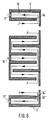
- the number of partitions ZW reaches the size (n-1). It can also be seen from FIG. 5 that the openings between adjacent heat exchange chambers are arranged in such a way that the coolant flows through the arrangement in a meandering manner.
- FIG. 6 now shows an example according to which two heat exchangers according to FIG. 5 are mutually coupled are so that they have the heat exchange chamber having the inflow 10 in common and form a working surface 2, 2 'at both ends as a boundary of a heat exchange chamber 12, 12'. From the heat exchange chamber having the inflow 10, the coolant flow is distributed in both directions with respect to FIG. 6 both upwards and downwards. In the example shown, the work surfaces 2, 2 'will have the same temperature difference over their course. However, if the inflow 10 is not placed in the middle between the work surfaces 2, 2 ', it can be achieved that the temperature difference between the two work surfaces is different.
- the heat exchangers are shown in principle in FIGS. 2 to 6.
- the construction of these heat exchangers from a stack of heat exchange plates appears expedient for the practical implementation.
- FIG. 7 An example of this is shown in FIG. 7 in an exploded view.
- Inflow 10 and outflow 11 for the coolant are again visible here and the upper heat exchange plate 20 forms a heat exchange surface or work surface 21 which closes a first heat exchange chamber 22.
- the chamber 22 Perpendicular to the heat exchange plate 20, the chamber 22 is followed by further chambers 23, 24 and 25, which are separated from one another by plates 26, 27 and 28 forming partition walls.
- the plate 29 closes the arrangement and thus the chamber 25 from below.
- overflow openings 30, 31 and 32 are formed in the plates 26 to 28, which as slots extending across the entire width of the plate are formed transversely to the flow of the coolant.
- a meandering flow for the coolant is given again by rotating adjacent plates, which can be identical to one another, by 180 degrees in the plate plane.
- FIG. 8 shows that the plates have a flange 33 all around the edge, so that adjacent plates can be inserted into one another in a form-fitting manner, optionally with the interposition of a sealing layer, and thus form heat exchange chambers sealed over the circumference.
- Figure 9 shows that the plates have an embossed groove along their edge. Between adjacent plates, a seal 35 is inserted into the groove, against which the bottom of the next plate comes into contact.
- Figure 8 can also be said that the adjacent plates with their flanges 33 can also be glued together.
- the seals 35 can also be glued to the adjacent plates.
- Figure 10 shows that adjacent panels are welded or soldered 36 together along their peripheral edge can be connected.
- the plates are again similar to those in FIG. 9, but every second plate is rotated by 180 ° about its longitudinal axis with respect to the previous one.
- 38 U-shaped profiles 39 are inserted between a plate 37 and the next, rotated plate and welded together with the plates.
- FIGS. 11 to 16 show the examples according to FIGS. 8 to 10 somewhat more completely. It can be seen from this that in the examples according to FIGS. 11, 13 and 15 the access opening 10 and the outlet opening 11 for the coolant are arranged on the side of the stack of plates, while in the examples according to FIGS. 12, 14 and 16 the inlet opening 10 and the outlet opening 11 for the coolant are arranged in the walls forming the chambers, from where a discharge pipe or the like connects at least to the outlet opening 11.
- the plate stack can be assembled as shown in FIGS. 11 to 16. If, however, larger chamber walls result, it is necessary to support adjacent chamber walls against one another in order to avoid deflections.
- This support can, as can be seen from FIG. 17, be formed by grids 40 interposed within the outer edge of the plates, which additionally increase the turbulence of the coolant within the heat exchange channels and thus ensure good heat transfer between adjacent plates.
- FIG. 18 shows that the plate 41 forming the work surface and the plate 45 forming the opposite end of the arrangement have a profile 68 oriented in the direction of flow of the coolant in order to support the inflow and outflow of the coolant.
- the intermediate plates 42 to 44 have, for example, a herringbone profile 69.
- the profiles can be produced from the plates by embossing if the plates are cut out of sheet metal.
- the profiling can also be produced by welding on material, gluing on material, soldering on material, in the production of cast plates by casting, by means of coating or by machining, spark erosion, arc erosion, chemical or electrochemical removal.
- the working surface of the plate 41 is also profiled by the embossed profiling shown there.
- such a design is only suitable for cooperation with gaseous or liquid media. Should objects, For example, the batteries mentioned are in contact with the work surface, the plate 41 must of course be smooth on the work side.
- the chamber walls or the plates are flat.
- the section shown in FIGS. 19 and 20 can be part of a circular cross section which forms a container or a flow tube in which the gaseous or liquid medium is cooled or heated.
- FIG. 21 shows the example of a plate heat exchanger in which both the coolant or heating medium inflow 10 and the outflow 11 are arranged in the surface of the base plate 49 opposite the plate 48 forming the working surface 2.
- the plates 50 to 55 which form the intermediate walls between the heat exchange chambers have bores 56 which are sealed or sealless with respect to the respective adjacent plate, in such a way that the coolant inflow only reaches every second heat exchange chamber 57 to 59, including the heat exchange chamber 59 adjacent to the first heat exchange chamber 60, in parallel to each other, while the coolant backflow also parallel to each other the other chambers 61, 62 and 63 flows through.
- the reversal between coolant inflow and coolant backflow takes place in the first heat exchange chamber 60.
- FIG. 22 shows a modification with regard to the overflow openings at least between the first heat exchange chamber 64 and the chamber 65 connected upstream of it.
- bores 67 are preferably arranged uniformly over their surface area, through which the coolant flowing to the chamber 65 flows in numerous ways Places flows into the chamber 64 and thereby comes against the back of the wall forming the work surface 2. This makes it possible in a simple manner to apply a certain cooling temperature to the wall having the working surface 2 on the back evenly at all points, so that there is also the same cooling effect over the entire extent of the working surface 2.
- FIG. 23 shows a supplementary design of the object according to FIG. 22. Thereafter, the coolant leaving the chamber 64 is passed from two chambers 68, 69 upstream of the chamber 65 via the chamber 68 in counterflow to the coolant fed into the chamber 65 via the chamber 69, to preheat the incoming coolant.
- FIG. 24, reversing the conditions according to FIG. 6, shows how the working surfaces 70, 71 of two first chambers 72, 73 arranged next to one another perpendicular to them are directed towards one another.
- the chambers 72, 73 are connected upstream of chambers 74, 75 to which the heating or Coolant flows in through openings 76, 77, whereupon it then leaves the chambers 72, 73 again through openings 78, 79.
- a chamber is formed between the working surfaces 70, 71, through which a gaseous or liquid medium can flow in order to heat or cool it.
- FIG. 25 shows how a first chamber 12 and a second chamber 13 connected upstream thereof are subdivided into a plurality of flow channels 80, 81 which are here essentially the same flow cross section and parallel to the flow direction of the coolant.
- the working wall of the chamber 12 again forms a working surface 2 into which the heat of batteries symbolized by the arrows 82 parallel to one another penetrates.
- the coolant enters the flow channels 81 via openings 10 and leaves the channels 80 via openings 11, the coolant flowing through a channel 81 being directed via a deflection 83 to an adjacent channel 80.
- adjacent channels 80 and 81 are connected in countercurrent, so that heat transfer takes place between adjacent channels 80 and 81 with one another and adjacent channels 80 and 81 with one another in accordance with arrows 84 and 85 and arrows 86.
- the design according to FIG. 25 permits a particularly stable design and, if appropriate, a better possibility of adaptation to special spatial conditions.
- the embodiment according to FIG. 26 largely corresponds to that according to FIG. 25 with the difference that the coolant is first passed back and forth between adjacent channels 81 via deflections 87, while it is then directed backwards and forwards accordingly between adjacent channels 80 via deflections 88 .
Abstract
Description
Die Erfindung betrifft einen Wärmeaustauscher mit einer ersten Wärmeaustauschkammer zum Kühlen oder Erwärmen von Gegenständen bzw. eines gasförmigen oder flüssigen Mediums, wobei eine Arbeitswand der ersten Wärmeaustauschkammer mit ihrer Arbeitsfläche mit den Gegenständen bzw. dem Medium in Verbindung steht, und wobei die Kammer zwischen einem Einlaß und einem Auslaß von einem Kühlmittel bzw. Heizmittel durchströmt ist, das die Arbeitswand auf der der Arbeitsfläche abgewandten Seite bestreicht.The invention relates to a heat exchanger with a first heat exchange chamber for cooling or heating objects or a gaseous or liquid medium, wherein a working wall of the first heat exchange chamber communicates with its working surface with the objects or the medium, and wherein the chamber between an inlet and an outlet is flowed through by a coolant or heating medium which brushes the work wall on the side facing away from the work surface.
Derartige Wärmeaustauscher finden in der chemischen Industrie, Biotechnologie und Medizintechnik als Heiz- oder Kühlkörper in Reaktoren, als Reaktorwände, bei Heiz- und Kühlbädern, als Heizsystem von chemischen Prozessen und als Wände von Prozeßschränken Verwendung. Ferner in der Lebensmittelindustrie zum Heizen oder Kühlen temperaturempfindlicher Produkte. Weiterhin als Wände von Klimagehäusen sowie für die Fußboden-, Decken-und Wandheizung. Schließlich ist ein besonderes Gebiet, auf das nachfolgend ohne Einschränkung im wesentlichen Bezug genommen wird, die Kühlung von wiederaufladbaren Batterien von Elektrofahrzeugen insbesondere Elektroautomobilen. Diese wiederaufladbaren Batterien sind dicht auf der Arbeitsfläche des Wärmeaustauschers montiert. Die bei der Entladung der Batterien freiwerdende Wärme wird durch das unter der Arbeitswand strömende Kühlmedium, beispielsweise Glykol, abgeführt. Die vom Kühlmedium aufgenommene Wärme geht dann über einen Luftkühler in die Umgebung.Such heat exchangers are used in the chemical industry, biotechnology and medical technology as heating or cooling elements in reactors, as reactor walls, in heating and cooling baths, as a heating system for chemical processes and as walls of process cabinets. Also in the food industry for heating or cooling temperature-sensitive products. Furthermore as walls of air conditioning housings as well as for floor, ceiling and wall heating. Finally, a special field, to which reference is made without restriction in the following, is the cooling of rechargeable batteries of electric vehicles, in particular electric vehicles. These rechargeable batteries are tight on the work surface of the heat exchanger assembled. The heat released when the batteries are discharged is dissipated by the cooling medium, e.g. glycol, flowing under the working wall. The heat absorbed by the cooling medium is then released into the environment via an air cooler.
Nachteilig bei diesem System ist, daß die Temperatur der kühlenden Arbeitsfläche über deren Erstreckung sehr unterschiedlich ist, da die Temperatur des Kühlmediums durch die Wärmezufuhr aus den Batterien steigt. Andererseits haben die Batterien einen optimalen Arbeitstemperaturbereich. Eine zu hohe Arbeitstemperatur verringert die Lebensdauer, während eine zu niedrige Arbeitstemperatur zu einem niedrigen Wirkungsgrad führt. Daraus ergibt sich, daß durch den bekannten Wärmeaustauscher optimale Arbeitsbedingungen für die Batterien nicht gewährleistet werden können eben wegen der entlang der Arbeitsfläche unterschiedlichen Temperaturen.A disadvantage of this system is that the temperature of the cooling work surface is very different over its extent, since the temperature of the cooling medium rises due to the supply of heat from the batteries. On the other hand, the batteries have an optimal working temperature range. A working temperature that is too high reduces the service life, while a working temperature that is too low leads to low efficiency. This means that the known heat exchanger does not guarantee optimal working conditions for the batteries, precisely because of the different temperatures along the working surface.
Besonders kraß werden diese Verhältnisse, wenn beim erneuten Starten des Fahrzeugs im Winter das Kühlmedium mit einer niedrigeren Temperatur direkt in den Wärmeaustauscher einfließt. Dies hat zur Folge, daß die im Bereich des Zuflusses des Kühlmittels angeordneten Batterien einen Temperaturschock erleiden, so daß die Leistung dieser Batterien wesentlich kleiner ist als die Nennleistung. Dies führt zu einer deutlichen Verringerung des Beschleunigungsvermögens des Fahrzeuges.These conditions become particularly bleak when the cooling medium flows directly into the heat exchanger at a lower temperature when the vehicle is restarted in winter. The result of this is that the batteries arranged in the area of the inflow of the coolant undergo a temperature shock, so that the output of these batteries is significantly less than the nominal output. This leads to a significant reduction in the vehicle's ability to accelerate.
Diese unangenehmen Erscheinungen gelten grundsätzlich auch für die oben genannten anderen Anwendungsgebiete, indem die mit der Arbeitsfläche in Berührung stehenden Gegenstände bzw. Medien über den Verlauf der Arbeitsfläche unterschiedlichen Temperaturen ausgesetzt sind.These unpleasant phenomena also apply in principle to the other fields of application mentioned above, in that the objects or media in contact with the work surface are exposed to different temperatures over the course of the work surface.
Aufgabe der Erfindung ist es daher, einen Wärmeaustauscher der eingangs genannten Art dahingehend weiterzubilden, daß sich über den Verlauf der Arbeitswand des Wärmetauschers bzw. dessen Arbeitsfläche eine möglichst gleichmäßige Temperatur ergibt.The object of the invention is therefore to develop a heat exchanger of the type mentioned in such a way that a temperature which is as uniform as possible results over the course of the working wall of the heat exchanger or its working surface.
Diese Aufgabe ist ausgehend von einem Wärmeaustauscher der eingangs genannten Art erfindungsgemäß dadurch gelöst, daß der Kammer senkrecht zur Arbeitswand wenigstens eine weitere Kammer vorgeschaltet ist, daß die weitere Kammer die der Arbeitswand der ersten Kammer gegenüberliegende wärmeleitende Wand mit der ersten Kammer gemeinsam hat, daß die weitere Kammer den Einlaß für das Kühl- bzw. Heizmittel aufweist, und daß das Kühl- bzw. Heizmittel von der weiteren Kammer in die erste Kammer zumindest indirekt übergeleitet wird.This object is achieved on the basis of a heat exchanger of the type mentioned at the outset in that at least one further chamber is connected upstream of the chamber perpendicular to the working wall, in that the further chamber has the heat-conducting wall opposite the working wall of the first chamber in common with the first chamber in that the further chamber has the inlet for the cooling or heating medium, and that the cooling or heating medium is at least indirectly transferred from the further chamber into the first chamber.
Diese Maßnahmen haben die Wirkung, daß die Temperaturdifferenz zwischen Eintritt des Kühl- bzw. Heizmittels in die erste Wärmeaustauschkammer und dem Austritt des Mittels aus dieser Kammer wesentlich herabgesetzt ist, bei einer vorgeschalteten weiteren Kammer um ca. 50 %, womit auch die Temperaturdifferenz zwischen den beiden in Strömungsrichtung des Mittels gesehenen Enden der Arbeitsfläche entsprechend verringert ist. Damit ist gleichzeitig bezüglich der Temperatur der Arbeitswand auch eine Unempfindlichkeit gegen Temperaturschwankungen des Kühl- bzw. Heizmittels am Einlaß erreicht.These measures have the effect that the temperature difference between the entry of the coolant or heating medium into the first heat exchange chamber and the outlet of the medium from this chamber is significantly reduced, with an upstream further chamber by about 50%, which also means the temperature difference between the both ends of the work surface seen in the direction of flow of the agent is correspondingly reduced. This means that insensitivity to temperature fluctuations in the coolant or heating medium at the inlet is also achieved with respect to the temperature of the working wall.
Schaltet man mehrere Wärmeaustauschkammern der ersten Wärmeaustauschkammer vor, so nimmt die genannte Temperaturdifferenz an der Arbeitsfläche entsprechend weiter ab, so daß man im Ergebnis an der Arbeitsfläche eine sehr geringe Temperaturdifferenz erhalten kann, wodurch die eingangs genannten negativen Erscheinungen (Temperaturschock etc.) vermieden sind.If several heat exchange chambers are connected upstream of the first heat exchange chamber, the temperature difference mentioned on the work surface decreases correspondingly further, so that the result is a work surface can receive very small temperature difference, whereby the negative phenomena mentioned above (temperature shock, etc.) are avoided.
Theoretisch ist es so, daß man durch unendlich viele vorgeschaltete Wärmeaustauschkammern eine konstante Temperatur über den gesamten Bereich der Arbeitsfläche erreichen kann. In der Praxis ist aber für die Gegenstände bzw. das Medium, welche gekühlt bzw. erwärmt werden sollen, ein gewisser Temperaturbereich unschädlich bzw. erlaubt.Theoretically, it is possible to achieve a constant temperature over the entire area of the work surface through an infinite number of upstream heat exchange chambers. In practice, however, a certain temperature range is harmless or permitted for the objects or the medium which are to be cooled or heated.
Zweckmäßig kann es sein, daß die gemeinsame Wand von erster und dieser benachbarter Kammer mit über ihrer Fläche insbesondere gleichmäßig verteilten Öffnungen zum Übertritt des Kühl- bzw. Heizmittels von der benachbarten Kammer in die erste Kammer versehen ist. Hiermit ergibt sich eine sehr gleichmäßige Temperatur der Arbeitsfläche, da diese auf ihrer Rückseite an allen Stellen von Kühl- bzw. Heizmittel über die Öffnungen angeströmt wird.It may be expedient for the common wall of the first and this adjacent chamber to be provided with openings, in particular evenly distributed over its surface, for the passage of the cooling or heating medium from the adjacent chamber into the first chamber. This results in a very uniform temperature of the work surface, since coolant or heating medium flows through the openings at its rear at all points.
Aus konstruktiven Gründen kann es vorteilhaft sein, daß die Kammern in mehrere zur Strömungsrichtung des Kühl- bzw. Heizmittels parallele Strömungskanäle unterteilt sind. Hier eröffnet sich einmal eine große Variationsvielfalt bezüglich des mit der Erfindung grundsätzlich vorgesehenen Strömungsverlaufes. Zum anderen läßt sich jedoch auch so leichter die Anpassung an bestimmte räumliche Gegebenheiten vornehmen.For design reasons, it can be advantageous for the chambers to be divided into a plurality of flow channels parallel to the direction of flow of the coolant or heating means. Here, a large variety of variations opens up with regard to the flow course fundamentally provided for by the invention. On the other hand, however, it is also easier to adapt to certain spatial conditions.
Zweckmäßigerweise kann vorgesehen sein, daß das Kühl- bzw. Heizmittel die Kammern nacheinander mäanderförmig durchströmt, was heißt, daß das Überströmen des Mittels bei nacheinander geschalteten Kammern abwechselnd mal auf der einen Seite und mal auf der anderen Seite der Gesamtanordnung erfolgt.It can be expediently provided that the cooling or heating means meander the chambers one after the other flows through, which means that the overflow of the agent takes place alternately on one side and sometimes on the other side of the overall arrangement with successively connected chambers.
Der Gegenstand der Erfindung ermöglicht leicht auch eine Verdopplung der Arbeitsflächen. Hierzu kann vorgesehen sein, daß bei zahlreichen senkrecht zur Arbeitswand hintereinander geschalteten Kammern bzw. Strömungskanälen die von der ersten Kammer am weitesten entfernte Kammer bzw. die von den ersten Strömungskanälen am weitesten entfernten Strömungskanäle ebenfalls mit ihrer Außenwand eine mit den Gegenständen bzw. einem gasförmigen oder flüssigen Medium in Verbindung stehende Arbeitsfläche bildet, daß das Kühl- bzw. Heizmittel der Kammeranordnung im Bereich zwischen den beiden Außenkammern, insbesondere in der Mitte zwischen diesen Außenkammern zuströmt, und daß das Kühl- bzw. Heizmittel ausgehend von der den Zustrom enthaltenden Kammer in Richtung auf beide Außenkammern aufgeteilt wird.The object of the invention also enables the work surfaces to be doubled. For this purpose, it can be provided that in the case of numerous chambers or flow channels connected in series perpendicular to the working wall, the chamber furthest away from the first chamber or the flow channels furthest away from the first flow channels also has an outer wall with the objects or a gaseous or Working surface in liquid medium forms that the coolant or heating means of the chamber arrangement flows in the area between the two outer chambers, in particular in the middle between these outer chambers, and that the coolant or heating means starts from the chamber containing the inflow in the direction is divided between the two outer chambers.
Normalerweise wird man, wie gesagt, den Zustrom des Kühl- bzw. Heizmittels in der Mitte zwischen den beiden äußeren Wärmaustauschkammern anordnen, so daß sich für beide Arbeitsflächen die gleiche Temperatur ergibt. Es besteht hier jedoch auch die Möglichkeit, den beiden Arbeitsflächen unterschiedliche Temperaturen zur Behandlung unterschiedlicher Güter bzw. Medien zu geben, was durch entsprechende außermittige Anordnung des Zuflusses des Kühl- bzw. Heizmittels erreicht werden kann. Ausgehend von der mittigen Anordnung kann dieses Ziel im übrigen auch, worauf später noch eingegangen wird, durch unterschiedliche Profilierung der einzelnen Zwischenwände zwischen den Kammern erreicht werden.Normally, as said, the inflow of the coolant or heating medium will be arranged in the middle between the two outer heat exchange chambers, so that the same temperature results for both work surfaces. However, there is also the option here of giving the two work surfaces different temperatures for treating different goods or media, which can be achieved by correspondingly off-center arrangement of the inflow of the coolant or heating medium. Starting from the central arrangement, this goal can also be achieved, as will be discussed later, by different profiling of the individual partition walls between the chambers.
Eine andere Möglichkeit besteht darin, daß die Arbeitsflächen zweier senkrecht zu diesen nebeneinander angeordneter erster Kammern aufeinander zu gerichtet sind, und daß zwischen den Arbeitsflächen ein Strömungsraum zum Kühlen oder Erwärmen eines gasförmigen oder flüssigen Mediums gebildet ist.Another possibility is that the working surfaces of two first chambers arranged perpendicular to one another are directed towards one another, and that a flow space for cooling or heating a gaseous or liquid medium is formed between the working surfaces.
Eine besondere Ausbildung kann dadurch gegeben sein, daß bei zahlreichen nebeneinander angeordneten Kammern die von der Arbeitswand am weitesten entfernte Wand sowohl den Einlaß als auch den Auslaß für das Kühl- bzw. Heizmittel aufweist, daß die zwischenliegenden Wände mit Durchtrittsöffnungen für den Zustrom und den Rückstrom des Mittels versehen sind, und daß miteinander fluchtende Öffnung benachbarter Wände derart gegenüber dem benachbarten Kammern abgedichtet bzw. dichtungslos sind, daß der Mittelzustrom parallel über jede zweite Kammer einschließlich der der ersten Kammer benachbarten Kammer erfolgt, während der Mittelrückstrom parallel über die übrigen Kammern erfolgt.A special design can be given in that in the case of numerous chambers arranged side by side, the wall furthest away from the working wall has both the inlet and the outlet for the coolant or heating means, that the intermediate walls have through openings for the inflow and the backflow of the agent are provided, and that the mutually aligned opening of adjacent walls is sealed or sealed against the adjacent chambers in such a way that the medium inflow takes place in parallel via every second chamber including the chamber adjacent to the first chamber, while the medium backflow takes place in parallel over the other chambers.
Auf diese Weise findet für das der ersten Kammer zuströmende Mittel in der ersten Kammer eine Umlenkung auf den Rückfluß statt, wobei die Kammeranordnung im übrigen nach Art eines Gegenstromkühlers bzw. Gegenstrom- Heizelementes arbeitet.In this way, a deflection to the reflux takes place in the first chamber for the agent flowing into the first chamber, the chamber arrangement otherwise operating in the manner of a countercurrent cooler or countercurrent heating element.
Zur konstruktiven Verwirklichung des Gegenstandes der Erfindung hat es sich als zweckmäßig erwiesen, daß die Wände durch Wärmeaustauschplatten gebildet sind. Hierbei kann vorgesehen sein, daß benachbarte Platten über ihren Umfang dicht miteinander verbunden sind, um einzelne gegenüber der Umgebung dichte Kammern zu bilden, was zum Beispiel durch Formschluß, umlaufende Dichtungen, Schweißen, Löten oder Kleben geschehen kann.For constructive implementation of the object of the invention, it has proven to be expedient that the walls are formed by heat exchange plates. It can be provided that adjacent plates are tightly connected to one another over their circumference in order to form individual chambers that are sealed from the environment. what can happen, for example, by positive locking, circumferential seals, welding, soldering or gluing.
Haben die einzelnen Kammerwände nur eine verhältnismäßig geringe Größe und mechanische Beanspruchung, so können diese grundsätzlich als glatte Flächen ausgebildet werden. Bei größerer Ausdehnung und damit höherer Beanspruchung der Kammerwände ist es jedoch zweckmäßig, daß die Wärmeaustauschflächen benachbarter Platten gegeneinander abgestützt sind.If the individual chamber walls have only a relatively small size and mechanical stress, they can in principle be designed as smooth surfaces. With larger expansion and thus higher stress on the chamber walls, however, it is expedient that the heat exchange surfaces of adjacent plates are supported against one another.
Diese Abstützung kann im einen Falle über Gitter, insbesondere aus Draht gegeben sein, wodurch die Turbulenz in den Kammern erhöht und damit der Wärmeübergang verbessert wird.In one case, this support can be provided via grids, in particular made of wire, which increases the turbulence in the chambers and thus improves the heat transfer.
Es kann jedoch auch vorgesehen sein, daß die Platten über eine an ihnen angebrachte Profilierung gegeneinander abgestützt sind. Diese Profilierung kann an den Platten durch Prägen, Schweißen, Kleben, Löten, Gießen, Beschichten oder durch spanendes funkenerosives, lichtbogenerosives, chemisches oder elektrochemisches Abtragen erzeugt werden. Durch die Profilierung läßt sich jedoch auch das Strömungsverhalten in den einzelnen Kammern insbesondere mit dem Ziel eines guten Wärmeübergangs beeinflussen oder aber auch dahingehend, daß bei der weiter oben beschriebenen Anordnung mit zwei Arbeitsflächen entweder der Mittelzustrom außermittig der Kammeranordnung angebracht werden kann, was aus räumlichen Gründen oft wünschenswert ist, oder daß ausgehend von einem beispielsweise mittigen Zufluß den beiden Arbeitsflächen unterschiedliche Temperaturen gegeben werden können.However, it can also be provided that the plates are supported against one another by a profiling attached to them. This profiling can be produced on the plates by stamping, welding, gluing, soldering, casting, coating or by machining spark erosion, arc erosion, chemical or electrochemical removal. By profiling, however, the flow behavior in the individual chambers can be influenced, in particular with the aim of good heat transfer, or else in such a way that in the arrangement described above with two work surfaces, either the central inflow can be attached off-center of the chamber arrangement, which for spatial reasons is often desirable, or that starting from a central inflow, for example, the two work surfaces can be given different temperatures.
Die vorstehende Bauform schließt auch eine Profilierung der Außenwand des oder der ersten Kammern ein, wobei diese Profilierung sich möglichst in Strömungsrichtung des Mittels erstrecken sollte. Eine solche Profilierung der Außenwand der ersten Kammer ist jedoch insbesondere für die Temperaturbeeinflussung von Gegenständen vielfach unerwünscht, so daß es gerade in diesem Falle vorteilhaft ist, daß die die Außenwand bildende Platte ohne Profilierung ausgebildet oder nur auf der den Gegenständen abgewandten Seite profiliert ist.The above design also includes profiling the outer wall of the first chamber or chambers, this profiling should extend as far as possible in the direction of flow of the agent. Such profiling of the outer wall of the first chamber is often undesirable, in particular for the temperature influence of objects, so that it is particularly advantageous in this case that the plate forming the outer wall is designed without profiling or is profiled only on the side facing away from the objects.
Die Kammerwände können eben ausgebildet sein. Je nach Anwendungsfall und räumlichen Verhältnissen kann es jedoch auch zweckmäßig sein, daß die Wände bezüglich der Gegenstände bzw. des Mediums konkav oder konvex ausgebildet sind.The chamber walls can be flat. Depending on the application and spatial conditions, however, it may also be appropriate for the walls to be concave or convex with respect to the objects or the medium.
Soweit bisher geschildert, sind die Kammern durch einen Spalt bzw. Plattenspalt gebildet. Im Rahmen der Erfindung liegt es jedoch auch selbstverständlich, daß die einzelnen Kammern aus mehreren parallel geschalteten Spalten bzw. Plattenspalten bestehen.As far as described so far, the chambers are formed by a gap or plate gap. Within the scope of the invention, however, it is also a matter of course that the individual chambers consist of several columns or plate columns connected in parallel.
Weitere erfindungswesentliche Merkmale und Einzelheiten ergeben sich aus der nachfolgenden Beschreibung von Ausführungsformen, die auf der Zeichnung dargestellt sind. In der Zeichnung zeigen:
Figur 1- eine Kühlanordnung für Batterien der bekannten Art in vereinfachter, perspektivischer Ansicht;
Figur 2- einen Schnitt durch den Wärmeaustauscher gemäß
Figur 1 mit graphischem Temperaturverlauf; Figur 3- eine erste Bauform nach der Erfindung mit graphischem Temperaturverlauf in der Darstellungsweise gemäß
Figur 2; - Figur 4 bis 6
- weitere Ausführungsformen nach der Erfindung, teilweise mit graphischem Temperaturverlauf in der Darstellungsweise gemäß
Figur 2; Figur 7- eine Prinzipdarstellung des erfindungsgemäßen Wärmeaustauschers in Plattenbauform;
Figur 8 bis 10- verschiedene Randabdichtungen der Wärmeaustauschkammern bei der Bauform gemäß
Figur 7; Figur 11 bis 16- die
Bauformen gemäß Figuren 7bis 10 mit unterschiedlicher Anordnung von Einlaß und Auslaß des Kühlmittels bzw. Heizmittels; Figur 17 und 18- unterschiedliche Formen der gegenseitigen Abstützung der den Wärmeaustauscher bildenden Platten;
- Figur 19 und 20
- Abwandlungen der Plattenform gegenüber den
Ausführungsformen gemäß Figur 7bis 18; Figur 21- eine Plattenbaufom mit abgewandeltem Strömungsverlauf des Kühl- bzw. Heizmittels;
Figur 22- die
Bauform gemäß Figur 3 mit abgewandeltem Überströmweg zwischen zwei benachbarten Kammern; Figur 23- eine besondere Ausbildung der Bauform gemäß Figur 22;
Figur 24- eine Umkehrvariante der Bauform gemäß Figur 6;
Figur 25 und 26- eine abgewandelte Ausbildung der Wärmeaustauschkammern.
- Figure 1
- a cooling arrangement for batteries of the known type in a simplified, perspective view;
- Figure 2
- a section through the heat exchanger according to Figure 1 with a graphical temperature profile;
- Figure 3
- a first design according to the invention with a graphical temperature profile in the representation according to Figure 2;
- Figure 4 to 6
- further embodiments according to the invention, partly with a graphical temperature profile in the representation according to FIG. 2;
- Figure 7
- a schematic diagram of the heat exchanger according to the invention in plate design;
- Figure 8 to 10
- different edge seals of the heat exchange chambers in the construction according to FIG. 7;
- Figure 11 to 16
- the designs according to Figures 7 to 10 with different arrangement of inlet and outlet of the coolant or heating medium;
- Figures 17 and 18
- different forms of mutual support of the plates forming the heat exchanger;
- Figure 19 and 20
- Modifications of the plate shape compared to the embodiments according to Figures 7 to 18;
- Figure 21
- a Plattenbaufom with modified flow of the coolant or heating medium;
- Figure 22
- the design according to Figure 3 with a modified overflow path between two adjacent chambers;
- Figure 23
- a special design of the design according to Figure 22;
- Figure 24
- a reverse variant of the design according to Figure 6;
- Figures 25 and 26
- a modified design of the heat exchange chambers.
Figur 1 zeigt einen gemäß Figur 2 ausgebildeten Wärmeaustauscher 1, auf dessen Arbeitsfläche 2 der Arbeitswand 3 dicht gepackt Batteriezellen 4 angeordnet sind.FIG. 1 shows a
Nach einem praktischen Beispiel können dies 200 Batteriezellen sein, die unter Vacuum stehen.According to a practical example, this can be 200 battery cells that are under vacuum.
Der Wärmeaustauscher 1 ist auf der der Wand 3 gegenüberliegenden Seite von einer Wand 5 begrenzt.The
Die so gebildete Wärmeaustauschkammer wird durch von einer Pumpe 6 umgetriebenes Kühlmittel 7 durchströmt, das die bei der Arbeit der Batteriezellen 4 entstehende Wärme abführt. Das Kühlmittel wird in einem Luftkühler 8 beispielsweise mittels eines Gebläses 9 rückgekühlt.The heat exchange chamber thus formed is flowed through by a
Wie die Graphik gemäß Figur 2 zeigt, ergibt sich für die Arbeitsfläche 2 zwischen Einlaß 10 und Auslaß 11 des Wärmeaustauschers ein Temperaturverlauf mit von te bis ta steigendem Verlauf.As the graph according to FIG. 2 shows, there is a temperature profile for the working
Aus der Elektrochemie ist bekannt, daß die dargestellte Batterie bei ca. 300° Celsius optimal arbeitet. Bei dem dargestellten bekannten Kühler erhält man jedoch ein Temperaturunterschied zwischen Einlaß 10 und Auslaß 11 von ca. 70° Celsius, also beispielsweise etwa einen Bereich von 330° Celsius bis 260° Celsius. Bekanntermaßen bedeutet jedoch eine zu hohe Arbeitstemperatur eine Verkürzung der Lebensdauer der Batteriezellen, während eine zu niedrige Arbeitstemperatur zu einem niedrigeren Wirkungsgrad führt.It is known from electrochemistry that the battery shown works optimally at approximately 300 ° Celsius. In the known cooler shown, however, a temperature difference between
Ist andererseits im Winter die Außentemperatur sehr niedrig, so kann bei vorhergehendem Stillstand des Motors zunächst im Bereich des Einlasses 10 für die Batteriezellen ein Temperaturschock entstehen, der den Wirkungsgrad und die Leistung der Batterien stark verringert.If, on the other hand, the outside temperature is very low in winter, a temperature shock can initially occur in the area of the
Um dem zu begegnen, zeigt Figur 3 eine erste prinzipielle Lösung. Hier ist senkrecht zur Arbeitsfläche 2 der Wärmeaustauschkammer 12 des ersten Wärmeaustauschers eine weitere Wärmeaustauschkammer 13 vorgeschaltet. Diese weitere Wärmeaustauschkammer 13 weist nunmehr den Einlaß 10 für das Kühlmittel auf, während der Auslaß 11 für das Kühlmittel bei der Wärmeaustauschkammer 12 des ersten Wärmeaustauschers verbleibt.To counter this, Figure 3 shows a first basic solution. Here, a further
Die beiden Wärmeaustauschkammern sind durch eine gemeinsame wärmeleitende Zwischenwand 14 getrennt, die über eine Öffnung 15 das Überströmen des Kühlmittels von der weiteren Wärmeaustauschkammer 13 auf die erste Wärmeaustauschkammer 12 erlaubt.The two heat exchange chambers are separated by a common heat-conducting
Bei dieser Bauform ergibt sich der in der Graphik gemäß Figur 3 dargestellte Temperaturverlauf zwischen den bereits aus Figur 2 ersichtlichen Temperaturen te und ta,wobei vermöge der Zwischenwand 14 etwa eine hälftige Aufteilung des Temperaturanstieges zwischen diesen beiden Werten erfolgt, so daß das Kühlmittel die erste Wärmeaustauschkammer 12 über die Öffnung 15 mit einer Temperatur tz1 erreicht, die etwa einen Mittelwert zwischen te und ta einnimmt. Dadurch tritt bereits eine erhebliche Vergleichmäßigung des Temperaturverlaufs entlang der Arbeitsfläche 2 (von rechts nach links in Figur 3) ein und der Temperaturunterschied liegt gegenüber dem Beispiel gemäß Figur 1 und 2 bereits unter 40° Celsius.With this design, the temperature curve shown in the graph according to FIG. 3 results between the temperatures t e and t a that can already be seen in FIG. 2, whereby the
Figur 4 zeigt eine Vermehrung auf drei Wärmeaustauschkammern, wobei die von der Arbeitsfläche 2 am weitesten entfernte Wärmeaustauschkammer 16 den Einlaß 10 für das Kühlmittel aufweist, während der Auslaß 11 wieder von der ersten Wärmeaustauschkammer 12 gebildet wird. Die zweite Wärmeaustauschkammer 13 ist wiederum von der dritten Wärmeaustauschkammer 16 durch eine wärmeleitende Zwischenwand 17 getrennt, wobei diese zwischen zweiter und dritter Wärmeaustauschkammer eine Überströmöffnung 18 läßt. Wie aus Figur 4 ersichtlich, sind die Überströmöffnungen 15, 18 so angeordnet, daß das Kühlmittel die Anordnung ausgehend von dem Einlaß 10 mäanderförmig durchströmt. Die zu Figur 4 gehörende Graphik zeigt, daß nunmehr das Gefälle zwischen te und ta in drei Abschnitte aufgeteilt ist mit Zwischenwerten tz1 und tz2. Dadurch ergibt sich zwischen tz2 und ta ein noch geringerer Temperaturanstieg und damit für die Arbeitsfläche 2 eine noch gleichmäßigere Temperaturverteilung.FIG. 4 shows an increase in three heat exchange chambers, the
Wie in Figur 5 angedeutet, kann man nun durch weitere Vergrößerung der Zahl hintereinander geschalteter Wärmeaustauschkammern die an der Arbeitsfläche 2 auftretende Temperaturdifferenz sehr klein machen, so daß sich bei n Wärmeaustauschkammern nur noch eine Temperaturdifferenz zwischen tzn und ta ergibt, die fast schon einer über den gesamten Bereich der Arbeitsfläche 2 gleichbleibenden Temperatur entspricht. Die Zahl der Zwischenwände ZW erreicht dabei die Größe (n-1). Auch aus Figur 5 ist wiederum ersichtlich, daß die Öffnungen zwischen benachbarten Wärmeaustauschkammern so angeordnet sind, daß das Kühlmittel die Anordnung mäanderförmig durchströmt.As indicated in FIG. 5, by further increasing the number of heat exchange chambers connected in series, the temperature difference occurring on the
Figur 6 zeigt nun ein Beispiel, gemäß dem zwei Wärmeaustauscher gemäß Figur 5 umgekehrt gegeneinander gekoppelt sind, so daß sie die den Zufluß 10 aufweisende Wärmeaustauschkammer gemeinsam haben und an beiden Enden je eine Arbeitsfläche 2, 2' als Begrenzung einer Wärmeaustauschkammer 12, 12' bilden. Von der den Zufluß 10 aufweisenden Wärmeaustauschkammer verteilt sich der Kühlmittelstrom in beide Richtungen bezogen auf Figur 6 sowohl nach oben als auch nach unten. Beim dargestellten Beispiel werden die Arbeitsflächen 2, 2' über ihren Verlauf die gleiche Temperaturdifferenz aufweisen. Legt man jedoch den Zufluß 10 nicht in die Mitte zwischen den Arbeitsflächen 2, 2' so läßt sich erreichen, daß die Temperaturdifferenz der beiden Arbeitsflächen unterschiedlich ist.FIG. 6 now shows an example according to which two heat exchangers according to FIG. 5 are mutually coupled are so that they have the heat exchange chamber having the
In den Figuren 2 bis 6 sind die Wärmeaustauscher mehr prinzipiell dargestellt. Für die praktische Ausführung erscheint der Aufbau dieser Wärmetauscher aus einer Stapelung von Wärmeaustauschplatten zweckmäßig.The heat exchangers are shown in principle in FIGS. 2 to 6. The construction of these heat exchangers from a stack of heat exchange plates appears expedient for the practical implementation.
Ein Beispiel hierfür zeigt Figur 7 in Explosionsdarstellung. Hier sind wieder Zufluß 10 und Abfluß 11 für das Kühlmittel ersichtlich und es bildet die obere Wärmeaustauschplatte 20 eine Wärmeaustauschfläche bzw. Arbeitsfläche 21, die eine erste Wärmeaustauschkammer 22 abschließt. Senkrecht zur Wärmeaustauschplatte 20 schließen sich an die Kammer 22 weitere Kammern 23, 24 und 25 an, die jeweils durch Zwischenwände bildende Platten 26, 27 und 28 voneinander getrennt sind. Die Platte 29 schließt die Anordnung und damit die Kammer 25 nach unten ab.An example of this is shown in FIG. 7 in an exploded view.
Wie aus Figur 7 ersichtlich, sind in den Platten 26 bis 28 Überströmöffnungen 30, 31 und 32 gebildet, die als sich quer zur Strömung des Kühlmittels praktisch über die gesamten Plattenbreite erstreckende Schlitze ausgebildet sind. Auch hier ist durch jeweils um 180 Grad in der Plattenebene erfolgte Drehung benachbarter Platten, die untereinander gleich sein können, wieder ein mäanderförmiger Fluß für das Kühlmittel gegeben.As can be seen from Figure 7,
Um den so die Kammern bildenden Plattenstapel bezüglich benachbarter Platten am Umfang abzudichten, kann beispielsweise von den Möglichkeiten gemäß Figur 8 bis 10 Gebrauch gemacht werden.In order to seal the plate stack thus forming the chambers with respect to adjacent plates on the circumference, use can be made, for example, of the possibilities according to FIGS. 8 to 10.
Figur 8 zeigt, daß die Platten randseits umlaufend eine Aufbördelung 33 aufweisen, so daß benachbarte Platten formschlüssig gegebenenfalls unter Zwischenlage einer Dichtschicht ineinander gesteckt werden können und so über den Umfang abgedichtete Wärmeaustauschkammern bilden.FIG. 8 shows that the plates have a
Figur 9 zeigt, daß die Platten entlang ihres Randes eine eingeprägte Nut aufweisen. Zwischen benachbarten Platten ist in die Nut eine Dichtung 35 eingesetzt, gegen die der Boden der nächstfolgenden Platte in Anlage kommt.Figure 9 shows that the plates have an embossed groove along their edge. Between adjacent plates, a
Zum Beispiel Figur 8 kann noch gesagt werden, daß hier die benachbarten Platten mit ihren Aufbördelungen 33 auch miteinander verklebt sein können. Entsprechend können auch die Dichtungen 35 mit den jeweils benachbarten Platten verklebt sein.For example, Figure 8 can also be said that the adjacent plates with their
Figur 10 zeigt, daß benachbarte Platten entlang ihres Umfangsrandes durch eine Schweißung oder Lötung 36 miteinander verbunden sein können. Beim dargestellten Beispiel sind die Platten wieder ähnlich wie in Figur 9 ausgebildet, wobei jedoch jede zweite Platte gegenüber der vorhergehenden um 180° um ihre Längsachse gedreht ist. Um auf diese Weise gleichmäßig beabstandete Wärmeaustauschkammern zu erhalten, sind zwischen einer Platte 37 und der nächstfolgenden, gedrehten Platte 38 U-förmige Profile 39 eingesetzt und zusammen mit den Platten verschweißt.Figure 10 shows that adjacent panels are welded or soldered 36 together along their peripheral edge can be connected. In the example shown, the plates are again similar to those in FIG. 9, but every second plate is rotated by 180 ° about its longitudinal axis with respect to the previous one. In order to obtain heat exchange chambers evenly spaced in this way, 38
Die Figuren 11 bis 16 zeigen die Beispiele gemäß Figur 8 bis 10 etwas vollständiger. Hieraus ist ersichtlich, daß bei den Beispielen gemäß Figur 11, 13 und 15 die Zutrittsöffnung 10 und die Auslaßöffnung 11 für das Kühlmittel seitlich des Plattenstapels angeordnet ist, während bei den Beispielen gemäß Figur 12, 14, und 16 die Einlaßöffnung 10 und die Auslaßöffnung 11 für das Kühlmittel in den die Kammern bildenden Wänden angeordnet sind, von wo aus sich zumindest an die Auslaßöffnung 11 ein Ableitungsrohr oder dergleichen anschließt.FIGS. 11 to 16 show the examples according to FIGS. 8 to 10 somewhat more completely. It can be seen from this that in the examples according to FIGS. 11, 13 and 15 the access opening 10 and the
Weisen die durch die einzelnen Platten gebildeten Kammerwände nur eine relativ kleine Oberfläche auf, so kann der Plattenstapel wie aus Figur 11 bis 16 ersichtlich zusammengesetzt werden. Ergeben sich jedoch großflächigere Kammerwände, so ist es erforderlich, benachbarte Kammerwände gegeneinander abzustützen, um Durchbiegungen zu vermeiden. Diese Abstützung kann, wie aus Figur 17 ersichtlich, durch innerhalb des Außenrandes der Platten zwischengelegte Gitter 40 gebildet sein, die zusätzlich die Turbulenz des Kühlmittels innerhalb der Wärmeaustauschkanäle erhöhen und damit für eine gute Wärmeübertragung zwischen benachbarten Platten sorgen.If the chamber walls formed by the individual plates have only a relatively small surface, the plate stack can be assembled as shown in FIGS. 11 to 16. If, however, larger chamber walls result, it is necessary to support adjacent chamber walls against one another in order to avoid deflections. This support can, as can be seen from FIG. 17, be formed by
Wie aus Figur 18 ersichtlich, besteht jedoch auch die Möglichkeit, den Platten 41 bis 45 eine Profilierung 68, 69 derart zu geben, daß die aufeinander zu gerichteten Profilteile benachbarter Platten aufeinander zu liegen kommen, in der Regel an den Kreuzungstellen benachbarter Profile punktförmig, so daß sich dadurch eine kammerbildende Beabstandung benachbarter Platten ergibt und gleichzeitig ebenfalls wieder eine gute Durchwirbelung des Kühlmittels und damit ein guter Wärmeübergang. Figur 18 zeigt, daß die die Arbeitsfläche bildende Platte 41 und die den gegenüberliegenden Abschluß der Anordnung bildende Platte 45 eine in Strömungsrichtung des Kühlmittels ausgerichtete Profilierung 68 aufweist, um Zu- und Abfluß des Kühlmittels zu unterstützen. Die dazwischenliegenden Platten 42 bis 44 weisen zum Beispiel eine fischgrätförmige Profilierung 69 auf.As can be seen from FIG. 18, however, there is also the possibility of giving the
Die Profilierungen können aus den Platten, wenn die Platten aus Blechtafeln ausgeschnitten sind, durch Prägen hergestellt werden. Die Profilierung kann jedoch auch durch Materialaufschweißen, Aufkleben von Material, Auflöten von Material, beim Herstellen gegossener Platten durch das Gießen, mittels Beschichtung oder durch spanendes, funkenerosives, lichtbogenerosives, chemisches oder elektrochemisches Abtragen erzeugt werden.The profiles can be produced from the plates by embossing if the plates are cut out of sheet metal. However, the profiling can also be produced by welding on material, gluing on material, soldering on material, in the production of cast plates by casting, by means of coating or by machining, spark erosion, arc erosion, chemical or electrochemical removal.
Beim Beispiel gemäß Figur 18 ist die Arbeitsfläche der Platte 41 durch die dort dargestellte, geprägte Profilierung ebenfalls profiliert. Eine solche Ausführung eignet sich allerdings nur für die Zusammenarbeit mit gasförmigen oder flüssigen Medien. Sollen Gegenstände, beispielsweise die erwähnten Batterien mit der Arbeitsfläche in Berührung stehen, muß die Platte 41 selbstverständlich auf der Arbeitseite glattflächig ausgebildet sein.In the example according to FIG. 18, the working surface of the
Bei allen bisherigen Beispielen sind die Kammerwände bzw. die Platten eben. Gerade in Zusammenwirken mit gasförmigen oder flüssigen Medien besteht jedoch auch die Möglichkeit, die Arbeitsflächen 46 bzw. 47 gegenüber dem gasförmigen oder flüssigen Medium konkav, wie dies Figur 19 zeigt, oder konvex, wie dies Figur 20 zeigt, auszubilden. Eine solche Ausbildung kann sich je nach Bauform des Wärmeaustauschers oder auch aus Platzgründen zweckmäßig erweisen. So kann insbesondere der in den Figuren 19 und 20 gezeigte Ausschnitt Teil eines Kreisquerschnittes sein, der einen Behälter oder ein Durchflußrohr bildet, in dem das gasförmige oder flüssige Medium gekühlt oder erwärmt wird.In all previous examples, the chamber walls or the plates are flat. In cooperation with gaseous or liquid media, however, there is also the possibility of making the work surfaces 46 or 47 concave, as shown in FIG. 19, or convex, as shown in FIG. 20. Depending on the design of the heat exchanger or also for reasons of space, such a training can prove expedient. In particular, the section shown in FIGS. 19 and 20 can be part of a circular cross section which forms a container or a flow tube in which the gaseous or liquid medium is cooled or heated.
Figur 21 zeigt das Beispiel eines Plattenwärmeaustauschers, bei dem sowohl der Kühl- bzw. Heizmittelzufluß 10 als auch der Abfluß 11 in der Fläche der der die Arbeitsfläche 2 bildenden Platte 48 gegenüberliegenden Bodenplatte 49 angeordnet sind. Die die Zwischenwände zwischen den Wärmeaustauschkammern bildenden Platten 50 bis 55 weisen gegenüber der jeweiligen benachbarten Platte abgedichtete bzw. dichtungslose Bohrungen 56 auf derart, daß der Kühlmittelzufluß jeweils nur jede zweite Wärmeaustauschkammer 57 bis 59 einschließlich der der ersten Wärmeaustauschkammer 60 benachbarten Wärmeaustauschkammer 59 erreicht und zwar parallel zueinander, während der Kühlmittelrückfluß ebenfalls parallel zueinander die übrigen Kammern 61, 62 und 63 durchströmt. Wie ersichtlich, findet dabei die Umkehr zwischen Kühlmittelzufluß und Kühlmittelrückfluß in der ersten Wärmeaustauschkammer 60 statt.FIG. 21 shows the example of a plate heat exchanger in which both the coolant or
Figur 22 zeigt eine Abwandlung bezüglich der Überströmöffnungen zumindest zwischen der ersten Wärmeaustauschkammer 64 und der dieser vorgeschalteten Kammer 65. Hier sind in der diesen Kammern gemeinsamen Zwischenwand 66 vorzugsweise gleichmäßig über deren Flächenbereich angeordnete Bohrungen 67 angebracht, über die das der Kammer 65 zuströmende Kühlmittel an zahlreichen Stellen in die Kammer 64 strömt und dabei gegen die Rückseite der die Arbeitsfläche 2 bildenden Wand gelangt. Hierdurch ist es auf einfache Weise möglich, die die Arbeitsfläche 2 aufweisende Wand auf der Rückseite an allen Stellen gleichmäßig mit einer bestimmten Kühltemperatur zu beaufschlagen, so daß sich über die gesamte Erstreckung der Arbeitsfläche 2 auch eine gleiche Kühlwirkung ergibt.FIG. 22 shows a modification with regard to the overflow openings at least between the first
Figur 23 zeigt eine ergänzte Bauform des Gegenstandes gemäß Figur 22. Danach ist von zwei der Kammer 65 vorgeschalteten Kammern 68, 69 das die Kammer 64 verlassende Kühlmittel über die Kammer 68 im Gegenstrom zu dem über die Kammer 69 in die Kammer 65 geführte Kühlmittel geleitet, um dem zuströmenden Kühlmittel eine Vorwärmung zu erteilen.FIG. 23 shows a supplementary design of the object according to FIG. 22. Thereafter, the coolant leaving the
Figur 24 zeigt in Umkehrung der Verhältnisse gemäß Figur 6, wie die Arbeitsflächen 70, 71 zweier senkrecht zu diesen nebeneinander angeordneter erster Kammern 72, 73 aufeinander zu gerichtet sind. Den Kammern 72, 73 sind Kammern 74, 75 vorgeschaltet, denen das Heiz- oder Kühlmittel über Öffnungen 76, 77 zuströmt, worauf es dann die Kammern 72, 73 über Öffnungen 78, 79 wieder verläßt.FIG. 24, reversing the conditions according to FIG. 6, shows how the working
Zwischen den Arbeitsflächen 70, 71 ist eine Kammer gebildet, die von einem gasförmigen oder flüssigen Medium durchströmt werden kann, um dieses zu heizen oder zu kühlen.A chamber is formed between the working
Figur 25 zeigt in Anlehnung an das Beispiel gemäß Figur 3, wie eine erste Kammer 12 und eine dieser vorgeschaltete zweite Kammer 13 in mehrere zur Strömungsrichtung des Kühlmittels parallele Strömungskanäle 80, 81 hier im wesentlichen gleichen Strömungsquerschnittes unterteilt sind. Dabei bildet die Arbeitswand der Kammer 12 wieder eine Arbeitsfläche 2, in die die durch die zueinander parallelen Pfeile 82 symbolisierte Wärme von Batterien eindringt.Based on the example according to FIG. 3, FIG. 25 shows how a
Das Kühlmittel tritt in die Strömungskanäle 81 über Öffnungen 10 ein und verläßt die Kanäle 80 über Öffnungen 11, wobei das einen Kanal 81 durchströmende Kühlmittel über eine Umlenkung 83 zu einem benachbarten Kanal 80 geleitet wird. Wie aus der Zeichnung ersichtlich, sind jeweils benachbarte Kanäle 80 bzw. 81 im Gegenstrom geschaltet, so daß zwischen benachbarten Kanälen 80 bzw. 81 untereinander sowie benachbarten Kanälen 80 und 81 miteinander ein Wärmeübergang entsprechend den Pfeilen 84 bzw. 85 sowie den Pfeilen 86 stattfindet. Die Gestaltung gemäß Figur 25 erlaubt in konstruktiver Hinsicht eine besonders stabile Ausbildung sowie gegebenenfalls eine bessere Anpassungsmöglichkeit an besondere räumliche Gegebenheiten.The coolant enters the
Die Ausführungsform gemäß Figur 26 entspricht weitestgehend der gemäß Figur 25 mit dem Unterschied, daß das Kühlmittel zunächst zwischen benachbarten Kanälen 81 über Umlenkungen 87 hin- und hergeführt wird, während es dann entsprechend zwischen benachbarten Kanälen 80 über Umlenkungen 88 im Gegenstrom hin- und hergeleitet wird.The embodiment according to FIG. 26 largely corresponds to that according to FIG. 25 with the difference that the coolant is first passed back and forth between
Claims (16)
dadurch gekennzeichnet,
daß der Kammer (12, 22, 60, 64, 80) senkrecht zur Arbeitswand (3, 20, 41, 48) wenigstens eine weitere Wärmeaustauschkammer (13, 23, 59, 65, 81) vorgeschaltet ist, daß die weitere Kammer die der Arbeitswand der ersten Kammer gegenüberliegende wärmeleitende Wand (14, 26, 50, 66) mit der ersten Kammer gemeinsam hat, daß die weitere Kammer den Einlaß (10) für das Kühl- bzw. Heizmittel aufweist, und daß das Kühl- bzw. Heizmittel von der weiteren Kammer in die erste Kammer zumindest indirekt übergeleitet (15, 30, 67, 83) wird.Heat exchanger having a first heat exchange chamber for cooling or heating objects or a gaseous or liquid medium, a working wall of the first heat exchange chamber communicating with its working surface with the objects or the medium, and wherein the chamber between an inlet and an outlet of a coolant or heating medium flows through, which brushes the work wall on the side facing away from the work surface,
characterized,
that the chamber (12, 22, 60, 64, 80) perpendicular to the working wall (3, 20, 41, 48) is connected upstream of at least one further heat exchange chamber (13, 23, 59, 65, 81), that the further chamber that the Working wall of the first chamber opposite heat-conducting wall (14, 26, 50, 66) has in common with the first chamber that the further chamber has the inlet (10) for the cooling or heating medium, and that the cooling or heating medium of the further chamber is at least indirectly transferred (15, 30, 67, 83) into the first chamber.
dadurch gekennzeichnet,
daß die gemeinsame Wand (66) von erster (64) und dieser benachbarter Kammer (65) mit über ihre Fläche insbesondere gleichmäßig verteilten Öffnungen (67) zum Übertritt des Kühl- bzw. Heizmittels von der benachbarten Kammer in die erste Kammer versehen ist.Heat exchanger according to claim 1,
characterized,
that the common wall (66) of the first (64) and this adjacent chamber (65) with its surface in particular uniformly distributed openings (67) for the passage of the coolant or heating medium from the adjacent chamber into the first chamber is provided.
dadurch gekennzeichnet,
daß die Kammern (12, 13) in mehrere zur Strömungsrichtung des Kühl- bzw. Heizmittels parallele Strömungskanäle (80, 81) unterteilt sind.Heat exchanger according to claim 1,
characterized,
that the chambers (12, 13) are divided into several flow channels (80, 81) parallel to the flow direction of the coolant or heating means.
dadurch gekennzeichnet,
daß das Kühl- bzw. Heizmittel die Kammern (12, 13) bzw. Strömungskanäle (80, 81) nacheinander mäanderförmig durchströmt.Heat exchanger according to one of claims 1 to 3,
characterized,
that the cooling or heating medium flows through the chambers (12, 13) or flow channels (80, 81) one after the other in a meandering manner.
dadurch gekennzeichnet,
daß bei zahlreichen senkrecht zur Arbeitswand hintereinander geschalteten Kammern (12,13, 16; 22, 23, 24, 25; 57 bis 63) bzw. Strömungskanälen (80, 81) die von der ersten Kammer (12, 22, 60) am weitesten entfernte Kammer (12') bzw. die von den ersten Strömungskanälen am weitesten entfernten Strömungskanäle ebenfalls mit ihrer Außenwand eine mit Gegenständen bzw. einem gasförmigen oder flüssigen Medium in Verbindung stehende Arbeitsfläche (2') bildet, daß das Kühl- bzw. Heizmittel der Kammeranordnung im Bereich zwischen den beiden Außenkammern, insbesondere in der Mitte zwischen diesen Außenkammern zuströmt, und daß das Kühl- bzw. Heizmittel ausgehend von der den Zustrom enthaltenden Kammer in Richtung auf die beiden Außenkammern aufgeteilt wird.Heat exchanger according to one of claims 1 to 4,
characterized,
that in the case of numerous chambers (12, 13, 16; 22, 23, 24, 25; 57 to 63) or flow channels (80, 81) connected in series perpendicular to the working wall, those of the first chamber (12, 22, 60) are the farthest The removed chamber (12 ') or the flow channels furthest from the first flow channels likewise forms with its outer wall a working surface (2') which is connected to objects or a gaseous or liquid medium, that the cooling or heating means of the chamber arrangement flows in the area between the two outer chambers, in particular in the middle between these outer chambers, and that the coolant or heating medium is divided from the chamber containing the inflow in the direction of the two outer chambers.
dadurch gekennzeichnet,
daß die Arbeitsflächen (70, 71) zweier senkrecht zu diesen nebeneinander angeordneter erster Kammern (72, 73) aufeinander zu gerichtet sind, und daß zwischen den Arbeitsflächen ein Strömungsraum zum Kühlen oder Erwärmen eines gasförmigen oder flüssigen Mediums gebildet ist.Heat exchanger according to one of claims 1 to 4,
characterized,
that the working surfaces (70, 71) of two first chambers (72, 73) arranged perpendicular to one another are directed towards one another, and that a flow space for cooling or heating a gaseous or liquid medium is formed between the working surfaces.
dadurch gekennzeichnet,
daß bei zahlreichen nebeneinander angeordneten Kammern (57 bis 63) die von der Arbeitswand (48) am weitesten entfernte Wand (49) sowohl den Einlaß (10) als auch den Auslaß (11) für das Kühl- bzw. Heizmittel aufweist, daß die zwischenliegenden Wände (50 bis 55) mit Durchtrittsöffnungen (56) für den Zustrom und den Rückstrom des Mittels versehen sind, und daß miteinander fluchtende Öffnungen benachbarter Wände derart gegenüber den benachbarten Kammern abgedichtet bzw. dichtungslos sind, daß der Mittelzustrom parallel über jede zweite Kammer (57, 58, 59) einschließlich der der ersten Kammer (60) benachbarten Kammer (59) erfolgt, während der Mittelrückstrom parallel über die übrigen Kammern (61, 62, 63) erfolgt.Heat exchanger according to one of claims 1 or 2,
characterized,
that in the case of numerous chambers (57 to 63) arranged side by side, the wall (49) furthest away from the working wall (48) has both the inlet (10) and the outlet (11) for the cooling or heating means, that the intermediate ones Walls (50 to 55) are provided with through openings (56) for the inflow and backflow of the agent, and that openings of adjacent walls which are in alignment with one another are sealed or sealless with respect to the adjacent chambers in such a way that the agent inflow runs in parallel over every second chamber (57 , 58, 59) including the chamber (59) adjacent to the first chamber (60), while the medium backflow takes place in parallel through the other chambers (61, 62, 63).
dadurch gekennzeichnet,
daß die Wände durch wärmeleitende Platten (20, 26 bis 28, 41 bis 44, 48, 50 bis 55) gebildet sind.Heat exchanger according to one of claims 1 to 7,
characterized,
that the walls are formed by heat-conducting plates (20, 26 to 28, 41 to 44, 48, 50 to 55).
dadurch gekennzeichnet,
daß benachbarte Platten (20, 26 bis 29, 41 bis 45, 48, 49, 50 bis 55) über ihren Umfang dicht miteinander verbunden sind.Heat exchanger according to claim 8,
characterized,
that adjacent plates (20, 26 to 29, 41 to 45, 48, 49, 50 to 55) are tightly connected to one another over their circumference.
dadurch gekennzeichnet,
daß die benachbarten Platten (20, 26 bis 29, 41 bis 45) gegeneinander abgestützt sind.Heat exchanger according to claim 8 or 9,
characterized,
that the adjacent plates (20, 26 to 29, 41 to 45) are supported against each other.
dadurch gekennzeichnet,
daß die Abstützung über Gitter (40), insbesondere aus Draht gegeben ist.Heat exchanger according to claim 10,
characterized,
that the support is given by grid (40), in particular made of wire.
dadurch gekennzeichnet,
daß die Platten über eine an ihnen angebrachte Profilierung (68, 69) gegeneinander abgestützt sind.Heat exchanger according to claim 10,
characterized,
that the plates are supported against each other by a profile (68, 69) attached to them.
dadurch gekennzeichnet,
daß die die Arbeitswand bildende Platte (20) ohne Profilierung ausgebildet oder nur auf der der Arbeitsfläche abgewandten Seite profiliert ist.Heat exchanger according to claim 10,
characterized,
that the plate (20) forming the work wall is designed without profiling or is profiled only on the side facing away from the work surface.
dadurch gekennzeichnet,
daß die Wände (3, 14, 17; ZW1 bis ZW (n - 1); 20, 26 bis 29; 41 bis 45) eben ausgebildet sind.Heat exchanger according to one of claims 1 to 13,
characterized,
that the walls (3, 14, 17; ZW1 to ZW (n - 1); 20, 26 to 29; 41 to 45) are flat.
dadurch gekennzeichnet,
daß die Wände bezüglich der Gegenstände bzw. des Mediums konkav ausgebildet sind.Heat exchanger according to one of claims 1 to 13,
characterized,
that the walls are concave with respect to the objects or the medium.
dadurch gekennzeichnet,
daß die Wände bezüglich der Gegenstände bzw. des Mediums konvex ausgebildet sind.Heat exchanger according to one of claims 1 to 13,
characterized,
that the walls are convex with respect to the objects or the medium.
Applications Claiming Priority (2)
| Application Number | Priority Date | Filing Date | Title |
|---|---|---|---|
| DE19944416236 DE4416236A1 (en) | 1994-05-07 | 1994-05-07 | Heat exchanger |
| DE4416236 | 1994-05-07 |
Publications (1)
| Publication Number | Publication Date |
|---|---|
| EP0681156A1 true EP0681156A1 (en) | 1995-11-08 |
Family
ID=6517613
Family Applications (1)
| Application Number | Title | Priority Date | Filing Date |
|---|---|---|---|
| EP19950104455 Withdrawn EP0681156A1 (en) | 1994-05-07 | 1995-03-27 | Heat exchanger |
Country Status (2)
| Country | Link |
|---|---|
| EP (1) | EP0681156A1 (en) |
| DE (1) | DE4416236A1 (en) |
Cited By (13)
| Publication number | Priority date | Publication date | Assignee | Title |
|---|---|---|---|---|
| EP0917230A1 (en) * | 1997-11-12 | 1999-05-19 | VARTA Aktiengesllschaft | Battery with temperature conditionning system |
| EP1178559A2 (en) * | 1998-03-05 | 2002-02-06 | Black & Decker Inc. | Battery cooling system |
| EP1207581A1 (en) * | 1999-08-27 | 2002-05-22 | TOKYO R & D Co., Ltd. | Battery cooling structure |
| WO2009052927A1 (en) * | 2007-10-19 | 2009-04-30 | Behr Gmbh & Co. Kg | Device for storing electrical energy |
| EP2443687A2 (en) * | 2009-06-18 | 2012-04-25 | Jason Fuhr | Battery module having a cell tray with thermal management features |
| WO2014082701A1 (en) * | 2012-11-28 | 2014-06-05 | Li-Tec Battery Gmbh | Battery with temperature-control device |
| FR3011131A1 (en) * | 2013-09-24 | 2015-03-27 | Valeo Systemes Thermiques | THERMAL BATTERY MANAGEMENT DEVICE AND METHOD OF MANUFACTURING THE SAME |
| EP3046178A1 (en) * | 2015-01-15 | 2016-07-20 | Saft | Battery provided with a device for thermal regulation of electrochemical elements, associated manufacturing method |
| US20170244143A1 (en) * | 2010-10-29 | 2017-08-24 | Dana Canada Corporation | Heat Exchanger And Battery Unit Structure For Cooling Thermally Conductive Batteries |
| DE102017205410A1 (en) * | 2017-03-30 | 2018-10-04 | Robert Bosch Gmbh | battery system |
| CN110462328A (en) * | 2017-05-05 | 2019-11-15 | 慕贝尔碳纤维技术有限公司 | Support construction |
| CN111834696A (en) * | 2020-06-09 | 2020-10-27 | 安徽正熹标王新能源有限公司 | Automobile battery temperature control system |
| CN113875073A (en) * | 2019-05-24 | 2021-12-31 | 法雷奥日本株式会社 | Battery cooling system |
Families Citing this family (2)
| Publication number | Priority date | Publication date | Assignee | Title |
|---|---|---|---|---|
| DE102008014155A1 (en) * | 2008-03-14 | 2009-09-17 | Magna Steyr Fahrzeugtechnik Ag & Co. Kg | Modular battery system with cooling system |
| DE102018127017A1 (en) * | 2018-10-30 | 2020-04-30 | Hanon Systems | Device for heat transfer for tempering batteries and components of power electronics |
Citations (2)
| Publication number | Priority date | Publication date | Assignee | Title |
|---|---|---|---|---|
| AT362106B (en) * | 1978-12-15 | 1981-04-27 | Peterschelka Karl | DEVICE FOR HEATING AIR WITH THE USE OF SOLAR ENERGY |
| JPS58157061A (en) * | 1982-03-12 | 1983-09-19 | Mitsubishi Electric Corp | Layer-built fuel cell |
Family Cites Families (2)
| Publication number | Priority date | Publication date | Assignee | Title |
|---|---|---|---|---|
| DE4134429C1 (en) * | 1991-10-18 | 1993-03-11 | Schroff Gmbh, 7541 Straubenhardt, De | Heat sink device for electronic cabinet - uses counterflow heat exchanger with vertical flow channels for cooling air stream and ambient air. |
| DE4307061A1 (en) * | 1993-03-06 | 1993-10-28 | Martin Gabler | Heat removal system for communications and control equipment - contains heat exchangers located on either side of insulating wall, connected by flow lines and forced cooled by fans which respectively directing air into and out of housing. |
-
1994
- 1994-05-07 DE DE19944416236 patent/DE4416236A1/en not_active Withdrawn
-
1995
- 1995-03-27 EP EP19950104455 patent/EP0681156A1/en not_active Withdrawn
Patent Citations (2)
| Publication number | Priority date | Publication date | Assignee | Title |
|---|---|---|---|---|
| AT362106B (en) * | 1978-12-15 | 1981-04-27 | Peterschelka Karl | DEVICE FOR HEATING AIR WITH THE USE OF SOLAR ENERGY |
| JPS58157061A (en) * | 1982-03-12 | 1983-09-19 | Mitsubishi Electric Corp | Layer-built fuel cell |
Non-Patent Citations (1)
| Title |
|---|
| PATENT ABSTRACTS OF JAPAN vol. 7, no. 276 (E - 215) 9 December 1983 (1983-12-09) * |
Cited By (27)
| Publication number | Priority date | Publication date | Assignee | Title |
|---|---|---|---|---|
| EP0917230A1 (en) * | 1997-11-12 | 1999-05-19 | VARTA Aktiengesllschaft | Battery with temperature conditionning system |
| US7326490B2 (en) | 1998-03-05 | 2008-02-05 | Black & Decker Inc. | Battery cooling system |
| EP1178559A2 (en) * | 1998-03-05 | 2002-02-06 | Black & Decker Inc. | Battery cooling system |
| EP1178557A2 (en) * | 1998-03-05 | 2002-02-06 | Black & Decker Inc. | Battery cooling system |
| US7939193B2 (en) | 1998-03-05 | 2011-05-10 | Black & Decker Inc. | Battery cooling system |
| EP1178557A3 (en) * | 1998-03-05 | 2003-12-03 | Black & Decker Inc. | Battery cooling system |
| EP1178559A3 (en) * | 1998-03-05 | 2003-12-17 | Black & Decker Inc. | Battery cooling system |
| US6949309B2 (en) | 1998-03-05 | 2005-09-27 | Black & Decker Inc. | Battery cooling system |
| US7014945B2 (en) | 1998-03-05 | 2006-03-21 | Black & Decker Inc. | Battery cooling system |
| US7056616B2 (en) | 1998-03-05 | 2006-06-06 | Black & Decker Inc. | Battery cooling system |
| US7252904B2 (en) | 1998-03-05 | 2007-08-07 | Black & Decker Inc. | Battery cooling system |
| EP1207581A1 (en) * | 1999-08-27 | 2002-05-22 | TOKYO R & D Co., Ltd. | Battery cooling structure |
| EP1207581A4 (en) * | 1999-08-27 | 2007-04-25 | Tokyo R & D Kk | Battery cooling structure |
| WO2009052927A1 (en) * | 2007-10-19 | 2009-04-30 | Behr Gmbh & Co. Kg | Device for storing electrical energy |
| EP2443687A4 (en) * | 2009-06-18 | 2014-07-02 | Jason Fuhr | Battery module having a cell tray with thermal management features |
| EP2443687A2 (en) * | 2009-06-18 | 2012-04-25 | Jason Fuhr | Battery module having a cell tray with thermal management features |
| US20170244143A1 (en) * | 2010-10-29 | 2017-08-24 | Dana Canada Corporation | Heat Exchanger And Battery Unit Structure For Cooling Thermally Conductive Batteries |
| US11056735B2 (en) * | 2010-10-29 | 2021-07-06 | Dana Canada Corporation | Heat exchanger and battery unit structure for cooling thermally conductive batteries |
| WO2014082701A1 (en) * | 2012-11-28 | 2014-06-05 | Li-Tec Battery Gmbh | Battery with temperature-control device |
| FR3011131A1 (en) * | 2013-09-24 | 2015-03-27 | Valeo Systemes Thermiques | THERMAL BATTERY MANAGEMENT DEVICE AND METHOD OF MANUFACTURING THE SAME |
| EP3046178A1 (en) * | 2015-01-15 | 2016-07-20 | Saft | Battery provided with a device for thermal regulation of electrochemical elements, associated manufacturing method |
| DE102017205410A1 (en) * | 2017-03-30 | 2018-10-04 | Robert Bosch Gmbh | battery system |
| CN110462328A (en) * | 2017-05-05 | 2019-11-15 | 慕贝尔碳纤维技术有限公司 | Support construction |
| US11376941B2 (en) | 2017-05-05 | 2022-07-05 | Mubea Carbo Tech Gmbh | Electric vehicle battery cooling structure |
| CN113875073A (en) * | 2019-05-24 | 2021-12-31 | 法雷奥日本株式会社 | Battery cooling system |
| CN113875073B (en) * | 2019-05-24 | 2023-08-15 | 法雷奥日本株式会社 | Battery cooling system |
| CN111834696A (en) * | 2020-06-09 | 2020-10-27 | 安徽正熹标王新能源有限公司 | Automobile battery temperature control system |
Also Published As
| Publication number | Publication date |
|---|---|
| DE4416236A1 (en) | 1995-11-09 |
Similar Documents
| Publication | Publication Date | Title |
|---|---|---|
| EP0521298B1 (en) | Heat exchange apparatus for dryer by refrigeration in compressed air plants | |
| EP0681156A1 (en) | Heat exchanger | |
| EP1856734B1 (en) | Micro-heat exchanger | |
| EP1682840B1 (en) | Heat exchanger in particular for motor vehicles | |
| DE10348803A1 (en) | Plate heat exchanger | |
| DE2521279B2 (en) | Heat exchanger with plate units arranged in layers | |
| EP1604163A1 (en) | Heat exchanger, particularly exhaust gas cooler for motor vehicles | |
| EP1955001A1 (en) | Cooling device for an internal combustion engine | |
| DE1601216A1 (en) | Plate heat exchanger | |
| DE1551489A1 (en) | Heat exchanger | |
| DE3423736C2 (en) | ||
| DE112007002451T5 (en) | heat exchanger device | |
| DE19651625A1 (en) | Ribbed-tube heat exchange system for charging air cooling | |
| DE10345695A1 (en) | Artificial resin heat exchanger for vehicle air conditioner has heat exchange plate parts and holding part formed integrally by extrusion of resin material | |
| DE102005002063A1 (en) | Stacking disk heat exchanger | |
| EP1770345A2 (en) | Heat exchange network and heat exchanger using same | |
| DE2916116A1 (en) | HEAT EXCHANGER | |
| DE2413165A1 (en) | RECHARGEABLE COUNTERFLOW PLATE HEAT EXCHANGER | |
| EP0386131B1 (en) | Countercurrent heat-exchanger | |
| DE102013215241A1 (en) | Heat exchanger | |
| DE102007047110B4 (en) | Heat exchangers, in particular absorbers for thermal solar collectors | |
| DE3512891A1 (en) | INTERCOOLER FOR INTERNAL COMBUSTION ENGINES | |
| CH527403A (en) | Parallel rib heat exchanger - whose ribs are of parallel pairs of plates with internal weirs | |
| AT396176B (en) | HEAT EXCHANGER FOR A WATER HEATER | |
| DE102019201127A1 (en) | Cooling device for cooling at least one battery module and motor vehicle with such a cooling device |
Legal Events
| Date | Code | Title | Description |
|---|---|---|---|
| PUAI | Public reference made under article 153(3) epc to a published international application that has entered the european phase |
Free format text: ORIGINAL CODE: 0009012 |
|
| AK | Designated contracting states |
Kind code of ref document: A1 Designated state(s): AT CH DE DK FR GB IT LI SE |
|
| 17P | Request for examination filed |
Effective date: 19960126 |
|
| 17Q | First examination report despatched |
Effective date: 19970312 |
|
| STAA | Information on the status of an ep patent application or granted ep patent |
Free format text: STATUS: THE APPLICATION HAS BEEN WITHDRAWN |
|
| 18W | Application withdrawn |
Withdrawal date: 19970521 |