EP0681105A2 - Scroll machine with reverse rotation protection - Google Patents
Scroll machine with reverse rotation protection Download PDFInfo
- Publication number
- EP0681105A2 EP0681105A2 EP94309572A EP94309572A EP0681105A2 EP 0681105 A2 EP0681105 A2 EP 0681105A2 EP 94309572 A EP94309572 A EP 94309572A EP 94309572 A EP94309572 A EP 94309572A EP 0681105 A2 EP0681105 A2 EP 0681105A2
- Authority
- EP
- European Patent Office
- Prior art keywords
- compressor
- valve
- scroll
- passageway
- suction
- Prior art date
- Legal status (The legal status is an assumption and is not a legal conclusion. Google has not performed a legal analysis and makes no representation as to the accuracy of the status listed.)
- Granted
Links
Images


Classifications
-
- F—MECHANICAL ENGINEERING; LIGHTING; HEATING; WEAPONS; BLASTING
- F04—POSITIVE - DISPLACEMENT MACHINES FOR LIQUIDS; PUMPS FOR LIQUIDS OR ELASTIC FLUIDS
- F04C—ROTARY-PISTON, OR OSCILLATING-PISTON, POSITIVE-DISPLACEMENT MACHINES FOR LIQUIDS; ROTARY-PISTON, OR OSCILLATING-PISTON, POSITIVE-DISPLACEMENT PUMPS
- F04C18/00—Rotary-piston pumps specially adapted for elastic fluids
- F04C18/02—Rotary-piston pumps specially adapted for elastic fluids of arcuate-engagement type, i.e. with circular translatory movement of co-operating members, each member having the same number of teeth or tooth-equivalents
-
- F—MECHANICAL ENGINEERING; LIGHTING; HEATING; WEAPONS; BLASTING
- F04—POSITIVE - DISPLACEMENT MACHINES FOR LIQUIDS; PUMPS FOR LIQUIDS OR ELASTIC FLUIDS
- F04C—ROTARY-PISTON, OR OSCILLATING-PISTON, POSITIVE-DISPLACEMENT MACHINES FOR LIQUIDS; ROTARY-PISTON, OR OSCILLATING-PISTON, POSITIVE-DISPLACEMENT PUMPS
- F04C28/00—Control of, monitoring of, or safety arrangements for, pumps or pumping installations specially adapted for elastic fluids
- F04C28/24—Control of, monitoring of, or safety arrangements for, pumps or pumping installations specially adapted for elastic fluids characterised by using valves controlling pressure or flow rate, e.g. discharge valves or unloading valves
- F04C28/26—Control of, monitoring of, or safety arrangements for, pumps or pumping installations specially adapted for elastic fluids characterised by using valves controlling pressure or flow rate, e.g. discharge valves or unloading valves using bypass channels
-
- F—MECHANICAL ENGINEERING; LIGHTING; HEATING; WEAPONS; BLASTING
- F04—POSITIVE - DISPLACEMENT MACHINES FOR LIQUIDS; PUMPS FOR LIQUIDS OR ELASTIC FLUIDS
- F04C—ROTARY-PISTON, OR OSCILLATING-PISTON, POSITIVE-DISPLACEMENT MACHINES FOR LIQUIDS; ROTARY-PISTON, OR OSCILLATING-PISTON, POSITIVE-DISPLACEMENT PUMPS
- F04C18/00—Rotary-piston pumps specially adapted for elastic fluids
- F04C18/02—Rotary-piston pumps specially adapted for elastic fluids of arcuate-engagement type, i.e. with circular translatory movement of co-operating members, each member having the same number of teeth or tooth-equivalents
- F04C18/0207—Rotary-piston pumps specially adapted for elastic fluids of arcuate-engagement type, i.e. with circular translatory movement of co-operating members, each member having the same number of teeth or tooth-equivalents both members having co-operating elements in spiral form
- F04C18/0215—Rotary-piston pumps specially adapted for elastic fluids of arcuate-engagement type, i.e. with circular translatory movement of co-operating members, each member having the same number of teeth or tooth-equivalents both members having co-operating elements in spiral form where only one member is moving
-
- F—MECHANICAL ENGINEERING; LIGHTING; HEATING; WEAPONS; BLASTING
- F04—POSITIVE - DISPLACEMENT MACHINES FOR LIQUIDS; PUMPS FOR LIQUIDS OR ELASTIC FLUIDS
- F04C—ROTARY-PISTON, OR OSCILLATING-PISTON, POSITIVE-DISPLACEMENT MACHINES FOR LIQUIDS; ROTARY-PISTON, OR OSCILLATING-PISTON, POSITIVE-DISPLACEMENT PUMPS
- F04C28/00—Control of, monitoring of, or safety arrangements for, pumps or pumping installations specially adapted for elastic fluids
- F04C28/06—Control of, monitoring of, or safety arrangements for, pumps or pumping installations specially adapted for elastic fluids specially adapted for stopping, starting, idling or no-load operation
-
- F—MECHANICAL ENGINEERING; LIGHTING; HEATING; WEAPONS; BLASTING
- F04—POSITIVE - DISPLACEMENT MACHINES FOR LIQUIDS; PUMPS FOR LIQUIDS OR ELASTIC FLUIDS
- F04C—ROTARY-PISTON, OR OSCILLATING-PISTON, POSITIVE-DISPLACEMENT MACHINES FOR LIQUIDS; ROTARY-PISTON, OR OSCILLATING-PISTON, POSITIVE-DISPLACEMENT PUMPS
- F04C28/00—Control of, monitoring of, or safety arrangements for, pumps or pumping installations specially adapted for elastic fluids
- F04C28/28—Safety arrangements; Monitoring
-
- F—MECHANICAL ENGINEERING; LIGHTING; HEATING; WEAPONS; BLASTING
- F04—POSITIVE - DISPLACEMENT MACHINES FOR LIQUIDS; PUMPS FOR LIQUIDS OR ELASTIC FLUIDS
- F04C—ROTARY-PISTON, OR OSCILLATING-PISTON, POSITIVE-DISPLACEMENT MACHINES FOR LIQUIDS; ROTARY-PISTON, OR OSCILLATING-PISTON, POSITIVE-DISPLACEMENT PUMPS
- F04C2270/00—Control; Monitoring or safety arrangements
- F04C2270/19—Temperature
-
- F—MECHANICAL ENGINEERING; LIGHTING; HEATING; WEAPONS; BLASTING
- F04—POSITIVE - DISPLACEMENT MACHINES FOR LIQUIDS; PUMPS FOR LIQUIDS OR ELASTIC FLUIDS
- F04C—ROTARY-PISTON, OR OSCILLATING-PISTON, POSITIVE-DISPLACEMENT MACHINES FOR LIQUIDS; ROTARY-PISTON, OR OSCILLATING-PISTON, POSITIVE-DISPLACEMENT PUMPS
- F04C2270/00—Control; Monitoring or safety arrangements
- F04C2270/21—Pressure difference
-
- F—MECHANICAL ENGINEERING; LIGHTING; HEATING; WEAPONS; BLASTING
- F04—POSITIVE - DISPLACEMENT MACHINES FOR LIQUIDS; PUMPS FOR LIQUIDS OR ELASTIC FLUIDS
- F04C—ROTARY-PISTON, OR OSCILLATING-PISTON, POSITIVE-DISPLACEMENT MACHINES FOR LIQUIDS; ROTARY-PISTON, OR OSCILLATING-PISTON, POSITIVE-DISPLACEMENT PUMPS
- F04C2270/00—Control; Monitoring or safety arrangements
- F04C2270/70—Safety, emergency conditions or requirements
- F04C2270/72—Safety, emergency conditions or requirements preventing reverse rotation
-
- F—MECHANICAL ENGINEERING; LIGHTING; HEATING; WEAPONS; BLASTING
- F05—INDEXING SCHEMES RELATING TO ENGINES OR PUMPS IN VARIOUS SUBCLASSES OF CLASSES F01-F04
- F05B—INDEXING SCHEME RELATING TO WIND, SPRING, WEIGHT, INERTIA OR LIKE MOTORS, TO MACHINES OR ENGINES FOR LIQUIDS COVERED BY SUBCLASSES F03B, F03D AND F03G
- F05B2270/00—Control
- F05B2270/10—Purpose of the control system
- F05B2270/109—Purpose of the control system to prolong engine life
- F05B2270/1097—Purpose of the control system to prolong engine life by preventing reverse rotation
-
- F—MECHANICAL ENGINEERING; LIGHTING; HEATING; WEAPONS; BLASTING
- F05—INDEXING SCHEMES RELATING TO ENGINES OR PUMPS IN VARIOUS SUBCLASSES OF CLASSES F01-F04
- F05B—INDEXING SCHEME RELATING TO WIND, SPRING, WEIGHT, INERTIA OR LIKE MOTORS, TO MACHINES OR ENGINES FOR LIQUIDS COVERED BY SUBCLASSES F03B, F03D AND F03G
- F05B2270/00—Control
- F05B2270/30—Control parameters, e.g. input parameters
- F05B2270/301—Pressure
- F05B2270/3015—Pressure differential
-
- F—MECHANICAL ENGINEERING; LIGHTING; HEATING; WEAPONS; BLASTING
- F05—INDEXING SCHEMES RELATING TO ENGINES OR PUMPS IN VARIOUS SUBCLASSES OF CLASSES F01-F04
- F05B—INDEXING SCHEME RELATING TO WIND, SPRING, WEIGHT, INERTIA OR LIKE MOTORS, TO MACHINES OR ENGINES FOR LIQUIDS COVERED BY SUBCLASSES F03B, F03D AND F03G
- F05B2270/00—Control
- F05B2270/30—Control parameters, e.g. input parameters
- F05B2270/303—Temperature
Definitions
- the present invention relates generally to scroll machines, and more particularly to the elimination of reverse rotation problems in scroll machines such as those used to compress refrigerant in refrigerating, air-conditioning and heat pump systems.
- Scroll machines are becoming more and more popular for use as compressors in both refrigeration as well as air conditioning and heat pump applications due primarily to their capability for extremely efficient operation.
- these machines incorporate a pair of intermeshed spiral wraps, one of which is caused to orbit relative to the other so as to define one or more moving chambers which progressively decrease in size as they travel from an outer suction port towards a center discharge port.
- An electric motor is normally provided which operates to drive the orbiting scroll member via a suitable drive shaft.
- scroll compressors depend upon a seal created between opposed flank surfaces of the wraps to define successive chambers for compression, suction and discharge valves are generally not required.
- suction and discharge valves are generally not required.
- the pressurized chambers and/or backflow of compressed gas from the discharge chamber to effect a reverse orbital movement of the orbiting scroll member and the associated drive shaft.
- This reverse movement often generates noise or rumble which may be considered objectionable and undesirable.
- This reverse operation may result in overheating of the compressor and/or other damage to the apparatus. Additionally, in some situations, such as a blocked condenser fan, it is possible for the discharge pressure to increase sufficiently to stall the drive motor and effect a reverse rotation thereof. As the orbiting scroll orbits in the reverse direction, the discharge pressure will decrease to a point where the motor again is able to overcome this pressure head and orbit the scroll member in the forward direction. However, the discharge pressure will again increase to a point where the drive motor is stalled and the cycle is repeated. Such cycling is undesirable in that it results in excessive stresses on various components within the compressor. These components must then be increased in size or complexity in order to withstand the excessive stresses caused by this undesirable cycling.
- An object of the present invention resides, in one embodiment, in the provision of a very simple and unique solenoid valve which can be easily assembled into a conventional gas compressor of the scroll type without significant modification of the overall compressor design, and which functions at compressor shut-down to allow gas flow from an area of intermediate pressure to an area of suction pressure. With intermediate pressure and suction pressure equalized, a leak is created from the discharge side of the compressor to the suction side of the compressor. This leak will balance the discharge gas with the suction gas thereby preventing discharge gas from driving the compressor in the reverse direction which in turn eliminates the normal shut-down noise associated with such reverse rotation.
- Another object of the present invention resides, in an alternate embodiment, in the provision of a very simple and unique mechanically operated valve which can also be easily assembled into a conventional scroll compressor without significant modification of the overall compressor design, and which also functions at compressor shut-down to allow gas flow from an area of intermediate pressure to an area of suction pressure. With intermediate pressure and suction pressure equalized, a leak is created from the discharge side of the compressor to the suction side of the compressor. This leak will balance the discharge gas with the suction gas, thereby preventing reverse rotation and the attendant shut-down noise associated therewith.
- Both of the primary embodiments of the present invention achieve the desired results utilizing a very simple valve which is positioned between an area of intermediate pressure and an area of suction pressure.
- the valve is actuated by a solenoid and in the second set of embodiments, the valve is actuated by a mechanical device. Additional embodiments are disclosed which also facilitate starting of the compressor which is especially applicable to compressors having low-starting-torque motors.
- a compressor 10 which comprises a generally cylindrical hermetic shell 12 having welded at the upper end thereof a cap 14.
- Cap 14 is provided with a refrigerant discharge fitting 18 which may have the usual discharge valve therein (not shown).
- Lower bearing housing 26 locates and supports within shell 12 two piece main bearing housing 24 and a motor 28 which includes a motor stator 30.
- a drive shaft or crankshaft 32 having an eccentric crank pin 34 at the upper end thereof is rotatably journaled in a bearing 36 in main bearing housing 24 and a second bearing 38 in lower bearing housing 26.
- Crankshaft 32 has at the lower end a relatively large diameter concentric bore 40 which communicates with a radially outwardly inclined smaller diameter bore 42 extending upwardly therefrom to the top of crankshaft 32. Disposed within bore 40 is a stirrer 44. The lower portion of the interior shell 12 defines an oil sump 46 which is filled with lubricating oil. Bore 40 acts as a pump to pump lubricating fluid up the crankshaft 32 and into bore 42 and ultimately to all of the various portions of the compressor which require lubrication.
- Crankshaft 32 is rotatively driven by electric motor 28 including motor stator 30, windings 48 passing therethrough and a motor rotor 50 press fitted on crankshaft 32 and having upper and lower counterweights 52 and 54, respectively.
- the upper surface of two piece main bearing housing 24 is provided with a flat thrust bearing surface 56 on which is disposed an orbiting scroll 58 having the usual spiral vane or wrap 60 on the upper surface thereof.
- a cylindrical hub Projecting downwardly from the lower surface of orbiting scroll 58 is a cylindrical hub having a journal bearing 62 therein and in which is rotatively disposed a drive bushing 64 having an inner bore 66 in which crank pin 34 is drivingly disposed.
- Crank pin 34 has a flat on one surface which drivingly engages a flat surface (not shown) formed in a portion of bore 66 to provide a radially compliant driving arrangement, such as shown in assignee's U.S. Letters Patent 4,877,382, the disclosure of which is hereby incorporated herein by reference.
- Oldham coupling 68 is also provided positioned between orbiting scroll 58 and bearing housing 24. Oldham coupling 68 is keyed to orbiting scroll 58 and a non-orbiting scroll 70 to prevent rotational movement of orbiting scroll member 58. Oldham coupling 68 is preferably of the type disclosed in assignee's copending application Serial No. 591,443, entitled “Oldham Coupling For Scroll Compressor” filed October 1, 1990, the disclosure of which is hereby incorporated herein by reference.
- Non-orbiting scroll member 70 is also provided having a wrap 72 positioned in meshing engagement with wrap 60 of orbiting scroll 58.
- Non-orbiting scroll 70 has a centrally disposed discharge passage 74 which communicates with an upwardly open recess 76 which in turn is in fluid communication via an opening 78 in partition 22 with a discharge muffler chamber 80 defined by cap 14 and partition 22.
- the entrance to opening 78 has an annular seat portion 82 therearound.
- Non-orbiting scroll member 70 has in the upper surface thereof an annular recess 84 having parallel coaxial sidewalls in which is sealingly disposed for relative axial movement an annular floating seal 86 which serves to isolate the bottom of recess 84 from the presence of gas under suction pressure at 88 and discharge pressure at 90 so that it can be placed in fluid communication with a source of intermediate fluid pressure by means of a passageway 92.
- Non-orbiting scroll member 70 is thus axially biased against orbiting scroll member 58 to enhance wrap tip sealing by the forces created by discharge pressure acting on the central portion of scroll member 70 and those created by intermediate fluid pressure acting on the bottom of recess 84.
- Non-orbiting scroll member 70 is designed to be mounted to bearing housing 24 in a suitable manner which will provide limited axial (and no rotational) movement of non-orbiting scroll member 70.
- Non-orbiting scroll member 70 may be mounted in the manner disclosed in the aforementioned U.S. Patent No. 4,877,382 or U.S. Patent No. 5,102,316, the disclosure of which is hereby incorporated herein by reference.
- the compressor is preferably of the "low side" type in which suction gas entering via fitting 20 is allowed, in part, to escape into the shell and assist in cooling the motor. So long as there is an adequate flow of returning suction gas the motor will remain within desired temperature limits. When this flow ceases, however, the loss of cooling will cause a motor protector 94 to trip and shut the machine down.
- both of the primary embodiments of the present invention utilize a very simple valve which functions at compressor shut down to allow gas flow from an area of intermediate pressure to an area of suction pressure.
- the valve of the present invention operates to allow gas at intermediate pressure to flow to an area of suction pressure which then allows discharge pressure to dump to suction pressure.
- the size, complexity and cost of the valve can be significantly reduced.
- the valve is operated by a solenoid, and in the second set of embodiments, the valve is run by a mechanical device. It is believed that all primary embodiments of the present invention are fully applicable to any type of scroll compressor.
- the first embodiment of the present invention is shown in Figures 1 through 3.
- the first embodiment makes use of the dual pressure balancing scheme described above which is used to axially balance non-orbiting scroll member 70 with floating seal 86 being used to separate the discharge gas pressure from the suction gas pressure.
- a solenoid valve 98 comprises a solenoid 100 and a valve 102. Solenoid valve 98 can be wired in parallel or in series with motor 28 such that solenoid 100 is activated and deactivated with motor 28 or solenoid valve 98 may be wired independently from motor 28. When solenoid valve 98 is wired independently from motor 28, valve 98 may be operated in a pulsed manner or a pulsed width modulated manner to modulate the capacity of compressor 10. Solenoid 100 is operable to open and close valve 102 which is in communication with a passageway 104 located within non-orbiting scroll 70. Passageway 104 extends from the bottom of recess 84 which is at intermediate pressure during operation of the compressor to the area of the compressor which contains suction gas at suction gas pressure.
- Solenoid 100 and valve 102 are best shown in Figure 2.
- Solenoid 100 includes a cylindrical wire coil 106 surrounding a plunger 108 in the usual manner.
- Solenoid 100 is secured to valve 102 by any method known well in the art.
- Valve 102 includes a valve body 110 having a passageway 112 which is in communication with passageway 104 in non-orbiting scroll 70.
- Valve body 112 is attached to non-orbiting scroll 70 by methods known well in the art.
- a ball 114 is disposed within passageway 112 and moveable between an open position and a closed position due to the movement of plunger 108. In its open position, fluid is allowed to flow from passageway 104 through passageway 112. In its closed position fluid is prohibited from flowing through passageways 104 and 112 due to ball 114 being forced against a valve seat 116 located within passageway 112 by plunger 108.
- solenoid 100 is energized and valve 102 is closed to block any fluid flow through passageway 104.
- compressor 10 makes a normal start-up.
- compression within the scrolls builds rapidly at start-up. This build up of pressure can be so rapid in fact that the compressor may stall because of insufficient motor torque. Generally, this is only a problem when using single phase motors. When this build up of pressure occurs, the motor stalls and the motor protector repeatedly trips and the compressor has a difficult time starting again.
- An option in the present invention is to build in a time delay to the activation of solenoid 100 to prevent the closing of passageway 104 at start-up, thus keeping intermediate pressure from building up. This lack of intermediate pressure will allow the scrolls to separate axially and prevent compression build-up until sufficient motor torque has been generated.
- solenoid 100 is de-energized at the same instant that power to motor 28 is cut off.
- the de-energization of solenoid 100 causes valve 102 to open and allows fluid flow through passageways 104 and 112 from the bottom of recess 84 to the suction area of compressor 10.
- floating seal 86 has a net downward force due to the discharge gas pressure and floating seal 86 moves downward in recess 84 and creates a discharge gas to suction gas leak across the top of floating seal 86 at annular seat portion 82.
- Solenoid valve 98 may be an AC (alternating current) or a DC (direct current) solenoid independent of the type of motor 28. If a DC solenoid is to be used with an AC motor, a rectifier needs to be wired between the AC power source and the DC solenoid.
- Figure 4 shows another embodiment of the present invention.
- elements which are the same as those in Figures 1 through 3 have been given the same reference numerals.
- the embodiment in Figures 1 through 3 purges intermediate pressure within recess 84 which holds non-orbiting scroll 70 down allowing floating seal 86 to drop.
- the embodiment shown in Figure 4 is incorporated into a compressor which uses intermediate pressure to bias orbiting scroll 58 upward.
- the embodiment shown in Figure 4 purges the intermediate pressure holding orbiting scroll 58 up which then creates sufficient tip clearance between the tips of scroll wraps 60 and 72 and their respective mating scroll to allow high pressure discharge gas to leak back through scrolls 58 and 70 before excessive reversals occur.
- FIG. 4 shows the upper section of a compressor 130.
- Compressor 130 is similar to compressor 10 with the exception that partition 22 of compressor 10 has been eliminated along with floating seal 86.
- non-orbiting, or in this case, stationary, scroll 70 extends completely across shell 12 and cap 14. Both shell 12 and cap 14 are secured to non-orbiting scroll 70 by welding or other means known well in the art.
- Main bearing housing 24 is provided with an annular chamber 132 extending into flat thrust bearing surface 56.
- a first annular seal 134 is positioned radially outward from chamber 132 and a second annular seal 136 is positioned radially inward from chamber 132. Seals 134 and 136 operate to prohibit fluid flow from chamber 132 to the suction side of compressor 130.
- a passageway 138 extends through orbiting scroll 58 and fluidically connects chamber 132 to an area of intermediate pressure within compressor 130. During operation of compressor 130, fluid at an intermediate pressure is supplied to chamber 132 through passageway 138. Orbiting scroll 58 is thus forced axially upward due to the fluid pressure within chamber 132. The fluid pressure within chamber 132 is maintained by seals 134 and 136.
- Compressor 130 further includes a passageway 140 extending through main bearing housing 24 and connecting chamber 132 to solenoid valve 98.
- the embodiment shown in Figure 4 includes a fluid tube 142 extending from passageway 140 to solenoid valve 98 which will allow the placement of solenoid valve 98 anywhere within the suction area of compressor 130 as space will permit. It will be appreciated that the use of tube 142 or its equivalent may be used with any of the embodiments of the present invention to facilitate packaging and design requirements. It is also possible to have tube 142 extend through shell 12 and have solenoid 100 and valve 102 located externally to shell 12 if desired.
- solenoid 100 is energized and valve 102 is closed to block any fluid flow from passageway 140 through passageway 112. In this way compressor 130 makes a normal start-up.
- the time delay feature at compressor start-up described above may also be built into solenoid valve 98 for this embodiment.
- solenoid 100 is de-energized causing valve 102 to open and allow fluid flow through passageways 140 and 112 from chamber 132 to the suction area of compressor 130. As the intermediate pressure and suction pressure are equalized, orbiting scroll 58 moves downward and creates a discharge gas to suction gas leak across the tips of scroll wraps 60 and 72.
- the amount of reverse rotation can be controlled by controlling the size of passageway 140 and/or passageway 112.
- the de-energization of valve 102 and the shutdown of motor 28 may also be tied in with a time delay to insure that sufficient leakage between chamber 132 and the suction area of the compressor has occurred before the motor is shut down. It is to be appreciated that this time delay feature at the shut down of the compressor can be applied to any of the embodiments of the present invention which incorporate solenoid valve 98.
- Figures 5 and 6 show another embodiment of the present invention.
- the embodiment shown in Figures 1 through 3 and the embodiment shown in Figure 4 utilize the purging of intermediate pressure from an existing chamber in the compressor which is being utilized to bias one of the scroll members towards the other.
- the effect of purging this intermediate pressure from a biasing chamber is to create a leak between existing compressor components which then allows the discharge gas pressure and suction gas pressure to equalize.
- FIG. 5 shows a compressor 150 having a pressure ratio sensitive valve 152 incorporated into orbiting scroll 58.
- the design of compressor 150 in Figure 5 is similar to the design of compressor 130 shown in Figure 4 in that non-orbiting scroll 70 is a fixed scroll attached to shell 12 and cap 14.
- Main bearing housing 24 is provided with annular chamber 132 extending into flat thrust bearing surface 56. Seals 134 and 136 operate to prohibit fluid flow from chamber 132 to the suction side of compressor 150.
- Passageway 138 extends through orbiting scroll 58 and connects chamber 132 to an area of intermediate pressure within compressor 150.
- the embodiment shown in Figure 5 includes a passageway 140 extending through main bearing housing 24 and connecting chamber 132 to solenoid valve 98.
- the embodiment shown in Figure 5 includes fluid tube 142 extending from passageway 140 which will allow the placement of solenoid valve 98 anywhere within the suction area of compressor 150 as space will permit.
- compressor 150 shown in Figure 5 is the same as compressor 130 shown in Figure 4 and the operation of compressor 150 is the same as the operation of compressor 130 as described above.
- Compressor 150 further includes pressure ratio sensitive valve 152 disposed within a pocket 154 located within orbiting scroll 58.
- a discharge pressure passageway 156 extends between discharge passageway 74 and pocket 154.
- a suction pressure passageway 158 extends between pocket 154 and the suction area of compressor 150.
- a valve body 160 is disposed within pocket 154 and is axially movable within pocket 154 to allow or prohibit fluid flow between passageway 156 and passageway 158.
- Valve body 160 and pocket 154 are designed such that valve body 160 is capable of axial movement within pocket 154 but fluid flow between valve body 160 and pocket 154 is prohibited.
- the upper surface of valve body 160 has an annular ring 162 which separates the area above valve body 160 into an annular chamber 164 and a cylindrical chamber 166.
- valve body 160 is determined by the various pressures operating against respective surface areas of valve body 160. Intermediate pressure within chamber 132 exerts an upward force on valve body 160 equal to the amount of intermediate pressure times the surface area of valve body 160 exposed to chamber 132.
- Discharge pressure is being supplied to annular chamber 164 and thus exerts a downward force on valve body 160 equal to the amount of discharge pressure times the surface area of valve body 160 exposed to chamber 164.
- suction pressure is being supplied to cylindrical chamber 166 and thus exerts a downward force on valve body 160 equal to the amount of suction pressure times the surface area of valve body 160 exposed to chamber 166.
- the opening and closing of pressure ratio sensitive valve 152 can be controlled by selecting the size of valve body 160 and the size and diameter of annular ring 162 to control the various surface areas.
- solenoid 100 is de-energized causing valve 102 to open and allow fluid flow through passageway 140 and 112 from chamber 132 to the suction area of compressor 150.
- both orbiting scroll 58 and valve body 160 are moved downward.
- the movement of scroll 58 causes a discharge gas to suction gas leak across the tips of scroll wraps 60 and 72 as explained above for the embodiment shown in Figure 4.
- the movement of valve body 160 within pocket 154 allows discharge gas to flow from passageway 156 through passageway 158 thus creating a direct fluid flow between the discharge gas and the suction gas.
- the various controls including the size of passageway 140 and/or passageway 112 and the time delay at compressor shut down described above for the embodiment shown in Figure 4 are also applicable to this embodiment.
- the amount of reverse rotation can be further controlled by the size of passageways 156 and 158 as well as the ratio of surface areas as described above for valve body 160.
- Figure 6 shows another embodiment of the present invention.
- Figure 6 shows a compressor 180 having a pressure ratio sensitive valve 182 disposed within a pocket located within non-orbiting or fixed scroll 70. Similar to the embodiment shown in Figures 1 through 3, compressor 180 includes fixed scroll 70, orbiting scroll 58, shell 12, cap 14 and partition 22. Compressor 180 has fixed scroll 70 bolted directly to partition 22 by a plurality of bolts 184. Because non-orbiting or fixed scroll 70 does not move axially as in Figures 1 through 3, the need for floating seal 86 has been eliminated. Compressor 180 may or may not utilize biasing chamber 132 located within main bearing housing 24 in conjunction with seals 134 and 136 to bias orbiting scroll 58 towards fixed scroll 70 in a manner similar to that described for the embodiment shown in Figure 4 but not shown in Figure 6.
- Compressor 180 includes pressure ratio sensitive valve 182 disposed within a pocket 186 located within fixed scroll 70.
- An intermediate pressure passageway 188 extends between an intermediate pressure zone within compressor 180 and pocket 186.
- a vent passageway 190 extends between pocket 186 and the inlet to solenoid valve 98.
- Solenoid valve 98 may be attached directly to fixed scroll 70 as shown in Figure 1 or it may be located remotely from fixed scroll 70 by using tube 142 as shown in Figures 4 and 6.
- a valve body 192 is disposed within pocket 186 and is axially movable within pocket 186 to allow or prohibit fluid flow through an orifice 194 extending through partition 22.
- Valve body 192 and pocket 186 are designed such that valve body 192 is capable of axial movement within pocket 186 but fluid flow between valve body 192 and pocket 186 is prohibited by sliding seal 196.
- the upper surface of valve body 192 has a cylindrical extension 198 which is adapted with a valve seat 200 for sealing orifice 194.
- valve body 192 is determined by the various pressures operating against respective surface areas of valve body 192. Intermediate pressure within pocket 186 exerts an upward force on valve body 192 equal to the amount of intermediate pressure times the surface area of the valve body 192.
- Discharge pressure is being supplied to orifice 194 and thus exerts a downward force on valve body 192 equal to the amount of discharge pressure times the area of orifice 194.
- suction pressure is present at the upper end of pocket 186 and thus exerts a downward force on valve body 192 equal to the amount of suction pressure times the surface area of valve body 192 minus the surface area of orifice 194.
- the opening and closing of pressure ratio sensitive valve 182 can be controlled by selecting the size of valve body 192 and the size of orifice 194.
- solenoid 100 is de-energized causing valve 102 to open and allow fluid flow through passageways 190 and 112 from pocket 186 to the suction area of compressor 180.
- valve body 192 moves downward due to discharge pressure at orifice 194.
- the movement of valve body 192 within pocket 186 creates a direct fluid flow between the discharge gas and the suction gas through orifice 194.
- the various controls including the size of passageway 190 and/or passageway 112 and the time delay at compressor shut down described for the embodiment in Figure 4 are also applicable to this embodiment.
- the amount of reverse rotation can be further controlled by the size of orifice 194 in relationship to the size of valve body 192 as described above.
- Figures 7 and 8 show another embodiment of the present invention.
- Figures 7 and 8 eliminate the need for solenoid valve 98.
- the compressor shown in Figures 7 and 8 utilize motor 28 and crankshaft 32 to perform the switching function of solenoid valve 98.
- a solenoid is basically a wire coil which generates a magnetic field, which in turn pushes or pulls a plunger within the coil. This is very similar to the compressor motor.
- Motor stator 30 creates a rotating magnetic filed which tends to axially center motor rotor 50 within motor stator 30.
- the embodiment shown in Figures 7 and 8 use this centering force in conjunction with an opposing spring force to create the same result as a solenoid.
- FIG. 7 shows compressor 220 which is similar to compressor 10 shown in Figure 1 except that solenoid valve 98 has been replaced by tube 142 and a valve 222 which uses motor 28 and crankshaft 32 for opening and closing.
- Passageway 104 extends through non-orbiting scroll 70 and is sealingly secured to tube 142.
- Tube 142 is routed through compressor 220 and its opposite end is sealingly secured to a passageway 224 extending through main bearing housing 24.
- Passageway 224 extends from one side of main bearing housing 24 to an upper surface 226 where it is open to the suction area of compressor 220.
- Crankshaft 32 extends through main bearing housing 24 and has an annular sealing flange 228 attached to crankshaft 32 at a position adjacent to upper surface 226.
- flange 228 is shown integral with crankshaft 32 and upper counterweight 52 is attached to flange 228. It is within the scope of the present invention to have flange 228 and counterweight 52 formed as one piece and attached to crankshaft 32 if desired.
- Crankshaft 32 is normally biased upward by a biasing spring 230 positioned between lower bearing housing 26 and crankshaft 32 such that sealing flange 228 is biased away from upper surface 226 and passageway 224 is open to the suction area of compressor 220.
- crankshaft 32 is forced downward against the load of biasing spring 230 due to the centering force created by the magnetic field of motor 28 which tends to axially center motor rotor 50 and thus crankshaft 32 within motor stator 30.
- This downward movement of crankshaft 32 brings into contact sealing flange 228 and upper surface 226 which prohibits fluid flow through passageway 224.
- compressor 220 makes a normal start-up.
- Figure 8 shows another embodiment of the present invention which is similar to the embodiment in Figure 4 but utilizes motor 28 and crankshaft 32 as the valve similar to that described above for Figure 7.
- Figure 8 shows a compressor 240 which includes an intermediate gas pressure basing chamber 132 similar to that shown in Figure 4.
- Compressor 240 also includes a passageway 242 which extends from a horizontal surface 244 on bearing housing 24 to meet a passageway 246 extending from biasing chamber 132.
- compressor 240 is identical to the operation of compressor 220 described above except that the intermediate pressure is released from below the orbiting scroll rather than from below floating seat 86 and the discharge gas to suction gas leak is created identical to that described in Figure 4.
- a pressure ratio sensitive valve as described in the embodiments shown in Figures 5 and 6 may also be incorporated into compressor 240 if desired.
- FIGS 9 and 10 show another embodiment of the present invention.
- the embodiment shown in Figures 9 and 10 makes use of centrifugal force to activate a valve above a predetermined rotational speed.
- This valve is biased to an open position at low speed allowing the purging of the intermediate pressure gas.
- this centrifugal valve can be utilized with any of the embodiments described above whereby the centrifugal valve replaces the solenoid valve.
- FIGS 9 and 10 show a compressor 250 which incorporates a centrifugal valve 252 to replace solenoid valve 98.
- Centrifugal valve 252 as best shown in Figure 10 includes a valve body 254 secured to crankshaft 32 for rotation therewith but capable of axial movement along crankshaft 32.
- a valve spring 256 biases valve body 254 axially along crankshaft 32 and sealingly engages valve body 254 with main bearing housing 24.
- a first passageway 258 extends radially through valve body 254.
- a valve 260 is slidingly received within passageway 258 and is biased radially inward by a coil spring 262. The radial outward end of passageway 258 is closed by a ball 264 which also provides for a reaction point for coil spring 262.
- valve body 254 which is opposite to valve spring 256 is provided with an annular groove 266 which is in communication with passageway 224 in main bearing housing 24.
- An axial passageway 268 extends from annular groove 266 through radial passageway 258 and into the suction area of compressor 250.
- passageway 224 is open to the suction area of compressor 250 through groove 266 and axial passageway 268.
- valve 260 will block axial passageway 268 and prohibit fluid flow from passageway 224 to the suction area of compressor 250.
- valve 260 is biased radially inward by coil spring 262. As the rotational speed of crankshaft 32 and centrifugal valve 252 increases, valve 260 is forced radially outward to block axial passageway 268. In this manner, compressor 250 makes a normal start-up.
- valve 260 At compressor shutdown, valve 260 will remain in a position to block axial passageway 268 until such a time that the load exerted by coil spring 262 exceeds the centrifugal force exerted on valve 260 as the rotational speed of centrifugal valve 252 decreases. Eventually valve 260 will move sufficiently inward to open axial passageway 268 and the intermediate pressure within passageway 224 will be purged to the suction area of compressor 250. The purging of the intermediate pressure to suction pressure has the identical effect as described above for the previous embodiments. The rate control for this embodiment would involve the size of axial passageway 268, the weight of valve 260 and the rate for coil spring 262.
- Figures 11 and 12 show schematically another embodiment of the present invention.
- the embodiment shown in Figures 11 and 12 uses angular acceleration at start-up to block a vent hole, and deceleration at shutdown to unblock the vent hole and allow the purging of intermediate gas pressure to suction gas pressure.
- Figures 11 and 12 schematically represent the reverse rotation protection of this embodiment of the present invention and include crankshaft 32, main bearing housing 24, passageway 224, a valve 280 and a collar 282.
- Valve 280 is located within passageway 224 at the point where passageway 224 extends through upper surface 244.
- Valve 280 includes a ball 284, an activation device 286 and a valve seat 288.
- Collar 280 is slidingly received on crankshaft 32 at a position adjacent to upper surface 244 on main bearing housing 24.
- Collar 282 includes a pin 290 which extends through collar 282 and is disposed in a spiral groove 292 located in crankshaft 32.
- a coil spring 294 biases collar 282 downward towards upper surface 244 on main bearing housing 24. In the lower position shown in Figure 11, collar 282 contacts activation device 286 which in turn forces ball 284 against valve seat 288 to prohibit movement of fluid through passageway 224.
- the intermediate pressure acting against ball 284 forces ball 284 upward opening passageway 224 to the suction area of the compressor.
- crankshaft 32 causes relative movement between crankshaft 32 and collar 282 due to the inertial effects on collar 282.
- the direction of spiral groove 292 is such that this positive angular acceleration of crankshaft 32 causes pin 290 to move downward in groove 292 forcing collar 282 against upper surface 226 and closing valve 280 by forcing ball 284 against valve seat 288. In this manner, the compressor makes a normal start-up.
- Figures 13 and 14 show another embodiment of the present invention.
- the embodiment shown in Figures 13 and 14 uses a viscous drag caused by a rotating component of the compressor.
- the rotating component shown is crankshaft 32, although any rotating component within the compressor could be used.
- Viscous drag caused by a rotating component can generate sufficient force to rotate a spring loaded device into a position to block a vent hole or to actuate a valve.
- Figures 13 and 14 schematically represent the reverse rotation protection of this embodiment of the present invention and include crankshaft 32, a collar 300 and a valve 302.
- Valve 302 includes a valve body 304, a valve spring 306, a first passageway 308, a valve 310 and a second passageway 312.
- Collar 300 is slidingly received on crankshaft 32 as shown in Figures 13 and 14.
- the relationship between the outside diameter of crankshaft 32 and the inside diameter of collar 300 is such that a viscous fluid film 314 exists between crankshaft 32 and collar 300.
- the rotating of crankshaft 32 attempts to shear viscous fluid film 314 between the two components. This shearing of the viscous fluid will cause a torque to be applied to collar 300 as viscous fluid film 314 attempts to rotate collar 300 with crankshaft 32.
- Collar 300 is provided with a radially extending paddle 316 which is used to activate valve 302 as will be described later herein.
- Valve body 304 may be secured to main bearing housing 24 similar to the attachment of valve 104 to non-orbiting scroll 70 shown in Figures 1 through 3 or valve body 304 may be separate from main bearing housing and provided with intermediate pressure by tube 142.
- First passageway 308 extends longitudinally through valve body 304.
- Valve 310 is slidingly received within passageway 308 and is biased towards paddle 316 of collar 300 as shown in Figure 13 by valve spring 306.
- the end of passageway 308 opposite to valve 310 is closed by a ball 318 which also provide for a reaction point for valve spring 306.
- Second passageway 312 extends through valve body 304 and through first passageway 308 generally perpendicular to first passageway 308. One end of second passageway 312 is connected to the source of intermediate pressure either directly through passageway 224 or through tube 142. The opposite end of second passageway 312 is open to the suction area of the compressor. When valve spring 306 biases valve 310 towards paddle 316, second passageway 312 is open and the source of intermediate pressure is open to the suction area of the compressor.
- paddle 316 exerts a load on valve 310 which overcomes the force of valve spring 306 and moves valve 310 to a position which blocks second passageway 312 and prohibits the source of intermediate pressure from purging to the suction area of the compressor.
- valve 310 is biased towards paddle 316 by valve spring 306.
- valve spring 306 As the rotational speed difference between crankshaft 32 and collar 300 increases, the torque exerted on collar 300 increases due to the shear of viscous fluid film 314 between crankshaft 32 and collar 300. The rotation of collar 300 with crankshaft 32 is prohibited by paddle 316 contacting valve 310.
- the load on valve 310 increases and valve 310 is forced longitudinally within first passageway 308 against valve spring 306 to block second passageway 312. In this manner, compressor 250 makes a normal start-up.
- valve 310 At compressor shutdown, valve 310 will remain in a position to block second passageway 312 until such a time that the load exerted by valve spring 306 exceeds the load exerted by paddle 316 on valve 310 as the rotational speed difference between crankshaft 32 and collar 300 decreases. Eventually valve 310 will move sufficiently inward to open second passageway 312 and the source of intermediate pressure will be purged to the suction area of the compressor.
- the purging of the intermediate pressure in this embodiment has the identical effect as described for the previous embodiments.
- the rate control for this embodiment would include the size of second passageway 312, the rate for valve spring 306 and the width of fluid film 314.
- Figures 15 through 17 illustrate schematically a fail-safe device which may be incorporated into a solenoid valve 350 which would be a replacement for solenoid valve 98 of the previous embodiments.
- Solenoid valve 350 operates similar to the operation of solenoid valve 98. Solenoid valve 98, when energized, pushes ball 114 onto valve seat 116 to prohibit fluid flow through passageway 112. Solenoid valve 350, when energized, moves away from a ball to allow the ball to seat on a valve seat. When solenoid valve 350 is de-energized it pushes the ball off of the valve seat to allow fluid flow through the valve.
- Figures 15 through 17 schematically illustrate solenoid valve 350 which includes a solenoid 352, a dashpot 354 and a valve 356.
- Solenoid 352 comprises a cylindrical wire coil 358, surrounding a plunger 360 in the usual manner.
- a return spring 362 forces plunger 360 towards the left as shown in Figure 15.
- Dashpot 354 comprises an outer housing 364 which is fixedly secured to plunger 360, an inner housing 366, and a dashpot spring 368.
- Inner housing 366 is slidingly received within a pocket 370 located within outer housing 364.
- Dashpot spring 368 is disposed within pocket 370 and urges inner housing 366 to the left as shown in Figure 15.
- Inner housing 366 includes an actuation pin 372 which extends from housing 366 towards valve 356 for opening and closing valve 356 as will be described later herein.
- Valve 356 comprises a valve body 374, a ball 376 and a valve spring 378.
- Valve body 374 includes a bore 380 extending longitudinally within valve body 374.
- Ball 376 is disposed within bore 380 and is urged to the right as shown in Figure 15 against a valve seat 382 by valve spring 378.
- the source of intermediate pressure is supplied to bore 380 either directly or by tube 142.
- solenoid valve 350 begins with solenoid 352 being de-energized, dashpot 354 being collapsed and valve 356 being closed due to valve spring 378 urging ball 376 against valve seat 382. This position is illustrated schematically in Figure 15. Activation pin 372 is biased against ball 376 by dashpot spring 368 but it is not able to unseat ball 376 due to the force exerted on ball 376 by valve spring 378. The rate of valve spring 378 is chosen to be higher than the rate of dashpot spring 368.
- solenoid 352 is energized and plunger 360 is urged to the right as shown in Figure 16. This urges outer housing 364 to the right also and dashpot 354 extends axially due to the load exerted by dashpot spring 368. This extension of dashpot 354 maintains the contact between activation pin 372 and ball 376. In this manner, the compressor will have a normal start-up.
- solenoid 352 is de-energized and plunger 360 is forced to the left as shown in Figure 17 due to return spring 362.
- the movement to the left of plunger 360 moves dashpot 354 to the left causing activation pin 372 to unseat ball 376 from valve seat 382.
- Valve spring 378 is unable to overcome the load exerted by activation pin 372 due to the force being exerted by return spring 362 and the resistance to collapsing of dashpot 354.
- the rate of return spring 362 is chosen to be higher than the rate of valve spring 378. Ball 376 will remain unseated from valve seat 382 for a period of time defined by the design of dashpot 354.
- Valve spring 378 will eventually work to collapse dashpot 354 and seat ball 376 against valve seat 382. This returns solenoid valve 350 to the position shown in Figure 15. During the time that ball 376 is unseated from valve seat 382, the gas at intermediate pressure will be purged to the suction area of the compressor. The purging of the intermediate pressure in this embodiment has the identical effect as described for the previous embodiments.
- the rate control for this embodiment would include the size of valve seat 382, the rates for springs 362, 368 and 378 as well as the rate for dashpot 354.
- solenoid valve 350 works by allowing valve 356 to remain seated if plunger 360 fails to retract at start-up, fails to return at shut-down or is stuck in any other position for whatever reason. If dashpot 354 itself fails, in either the collapsed or extended position, the compressor will function in a normal manner albeit with a loud shut-down.
- Figures 18 and 19 show another embodiment of the present invention.
- the purging of the intermediate pressurized gas to the suction area of the compressor was directly related to the start-up and shut-down of the compressor.
- the embodiment shown in Figures 18 and 19 uses a thermal switch to activate the purging of the source of intermediate pressurized gas to the suction area of the compressor. Once the thermal protector is switched, the dumping of the source of intermediate pressurized gas will allow discharge gas to leak to the suction area of the compressor as detailed above in the previous embodiments. The discharge gas to suction leak will lower the operating pressure ratio of the compressor and the discharge side temperature. Eventually the motor protector for the compressor will take the compressor off line due to high temperature discharge gas being leaked to the suction area of the compressor where the motor and motor protector are located.
- FIGS 18 and 19 illustrate schematically the thermal responsive valve of the present invention which is generally designated by reference numeral 400.
- Valve 400 comprises a valve body 402, a first chamber 404, a second chamber 406, a discharge pressure passageway 408 and a suction pressure passageway 410.
- Valve body 402 can be a separate component or valve body 402 may be an integral part of non-orbiting scroll 70, main bearing housing 24 or any other component within the compressor.
- First chamber 404 extends into valve body 402 and is placed in communication with the discharge gas of the compressor.
- Discharge pressure passageway 408 extends from the lower end of chamber 404 and fluidically connects chamber 404 with the lower end of chamber 406.
- a therm-o-disc (TOD) 410 is located on the step formed by chamber 404 and passageway 408. TOD 410 remains seated prohibiting discharge gas flow from chamber 404 to passageway 408. When a predetermined critical temperature is encountered, TOD 410 opens and allows full flow of discharge gas from chamber 404 to passageway 408.
- Second chamber 406 is a stepped chamber also extending into valve body 402.
- the upper or larger portion of chamber 406 is placed in communication with the source of intermediate pressurized gas.
- the lower or smaller portion of chamber 406 is placed in communication with chamber 404 through passageway 408.
- Suction pressure passageway 410 extends from a suction gas area within the compressor to the lower portion of chamber 406. The point at which suction pressure passageway 410 enters chamber 406 is between high pressure passageway 408 and the upper or larger portion of chamber 406.
- a flat check valve 412 having a piston 414 extending from it is disposed within chamber 406.
- Flat check valve 412 and piston 414 move together within chamber 406 from a closed position as shown in Figure 18 to an open position as shown in Figure 19.
- a retainer 416 limits the movement of flat check valve 412 and piston 414 within chamber 406.
- flat check valve 412 In its closed position, as shown in Figure 18, flat check valve 412 seats against the step formed in chamber 406 to prohibit fluid flow from the source of intermediate pressurized gas being supplied to the upper portion of chamber 406 to suction pressure passageway 410.
- Flat check valve 412 is forced downward due to the intermediate pressurized gas reacting on the exposed area of the step of check valve 412 and suction gas pressure reacting on the exposed area of piston 414.
- Flat check valve 412 will be forced upward due to the discharge gas pressure acting against piston 414 when TOD 410 is in the open condition. In its open position, as shown in Figure 19, flat check valve 412 is lifted from the stepped portion of chamber 406 and gas at intermediate pressure is allowed to leak to the suction side of the compressor. Retainer 416 limits the movement of flat check valve 412 such that discharge gas within passageway 408 is not allowed to flow into the suction area of the compressor.
- Thermal responsive valve 400 is normally positioned as shown in Figure 18. Discharge gas is being supplied to chamber 404 and intermediate pressurized gas is being supplied to chamber 406. The compressor operates normally as long as TOD 410 remains closed. When TOD 410 experiences an over temperature condition of the discharge gas within chamber 404, TOD 410 opens and allows discharge gas to enter passageway 408. The pressure of the discharge gas reacts against the exposed surface area of piston 414 raising flat check valve 412 which allows the source of intermediate pressurized gas in communication with chamber 406 to purge through passageway 410 and into the suction area of the compressor. This purging of the intermediate gas within the compressor allows a discharge gas to suction gas leak with the effects as described above for the various embodiments.
- the motor will continue to run with the compressor having a lower operating pressure ratio and a lower discharge side temperature. The motor will continue to run until the motor protector takes the compressor of line due to the high temperature discharge gas being leaked into the suction area of the compressor where the motor and motor protector are located.
- Figures 20 through 22 illustrate another embodiment of the present invention.
- Figures 20 through 22 show a compressor 500 which incorporates unique floating seal basing means 510.
- the reference numerals shown in Figures 20 through 22 which are identical to those shown in Figures 1 through 3 respectably depict like or corresponding components in both figures.
- Compressor 500 incorporates biasing means 510 in order to be able to control the rate at which intermediate pressure is bled to suction pressure which will in turn control the rate at which discharge pressure is bled to suction pressure. It has been found that dumping the intermediate pressure too quickly will cause compressor 500 to coast and become noisy. Pumping the intermediate pressure too slowly introduces the problems associated with reverse rotation of compressor 500. Thus, it is desirable to control the rate of dumping intermediate pressure to suction pressure which will in turn control the rate at which discharge pressure is dumped to suction pressure.
- Biasing means 510 comprises a plurality of coil springs 512 and a pair of spacing rings 514 and 516.
- Coil springs 512 are disposed between spacing rings 514 and 516.
- Each spacing ring 514 and 516 define a plurality of circumferentially spaced tabs 518 which both position and retain the plurality of coil springs 512 between plates 514 and 516.
- Plate 514, plate 516 and coil springs 512 are located between transversely extending partition 22 and floating seal 86 such that floating seal 86 is biased by coil springs 512 away from partition 22. This biasing of floating seal 86 acts to control the rate of opening the discharge gas to suction gas leak across the top of floating seal 86 at annular seat portion 82.
- solenoid 100 is energized and valve 102 is closed to block any fluid flow through passageway 104.
- compressor 500 makes a normal start-up because the pressure in cavity 84 increases quickly to overcome the biasing load of coil springs 512.
- the option to build in a time delay to the activation of solenoid 100 to improve start-up operation can be incorporated into compressor 500 similar to that described for compressor 10 if desired.
- solenoid 100 is de-energized at the same instant that power to motor 28 is cut off.
- the de-energizing of solenoid 100 causes valve 102 to open and allows fluid flow through passageways 104 and 112 from recess 84 to the suction area of compressor 500.
- the plurality of springs 512 helps to control the rate of dumping of intermediate pressure to suction pressure and as intermediate pressure and suction pressure become equalized, floating seal 86 has a net downward force due to discharge gas pressure and the plurality of coil springs 512 and floating seal 86 moves downward in recess 84 and creates a discharge gas to suction gas leak across the top of floating seal 86 at annular seat portion 82.
- the plurality of coil springs 512 help to control the rate of dumping of intermediate pressure gas to suction pressure which controls the rate of downward movement of floating seal 86 which in turn controls the rate of discharge gas to suction gas dumping.
- reverse rotation of compressor 500 may be minimized to any acceptable reverse RPM or it can be completely eliminated.
- Figures 23 and 24 each show another embodiment of the present invention which is similar to the embodiment shown in figures 5 and 6 respectively.
- the embodiments shown in Figures 23 and 24, similar to the embodiments shown in Figures 5 and 6 include a pressure ratio sensitive valve which directly passes discharge pressure to suction pressure.
- Figure 23 shows a compressor 550 having pressure ratio sensitive valve 152 incorporated into orbiting scroll 58.
- the reference numerals shown in Figure 23 which are identical to those shown in Figure 5 depict like or corresponding components in both figures.
- Biasing means in the form of a coil spring 552 is disposed between valve 152 and orbiting scroll 58 in order to bias valve 152 into an open position such that there is communication between the discharge area and the suction area of compressor 550.
- compressor 550 The operation of compressor 550 is similar to compressor 150 shown in Figure 5 except for the interaction of coil spring 552.
- solenoid 100 is energized and valve 102 is closed to block any fluid flow from passage 140 through passageway 112. Intermediate pressure builds quickly within chamber 132 overcoming the biasing load of coil spring 552.
- Valve 152 is prevented from seating on the lower surface of chamber 132 by methods known well in the art in order to insure that the fluid pressure within chamber 132 is always acting on the lower surface of valve 152. In this way, compressor 550 makes a normal start-up.
- the time delay feature for compressor start-up may also be build into solenoid valve 98 for this embodiment if desired. While compressor 550 is in operation valve 152 operates similar to the operation described for Figure 5.
- the opening and closing of pressure ratio sensitive valve 152 can be controlled by selecting the size of coil spring 552, the size of valve body 160 and the size and diameter of annular ring 162 to control the loading being applied to valve body 160.
- coil spring 552 helps to control the rate of dumping of intermediate pressure gas to suction pressure which controls the rate of downward movement of valve 152 which in turn controls the rate of discharge gas to suction gas dumping.
- the various controls including the size of coil spring 552, the size of passageway 140 and/or passageway 122 and the time delay at compressor shut down described above for the embodiment in Figure 5 and Figure 6 are also applicable to this embodiment.
- the amount of reverse rotation can be further controlled by the size of passageways 156 and 158 the size of coil spring 552 as well as the ratio of surface areas as described above for valve body 160.
- Figure 24 shows a compressor 580 similar to compressor 180 shown in figure 6 but with the addition of biasing means in the form of a coil spring 582 for biasing pressure ratio sensitive valve 182 into an open position.
- biasing means in the form of a coil spring 582 for biasing pressure ratio sensitive valve 182 into an open position.
- valve 182 When valve 182 is on its open position, the discharge area of compressor 580 is in communication with the suction area.
- valve body 192 The operation of the embodiment shown in Figure 24 is identical to the embodiment shown in Figure 6 except for the effects of coil spring 582.
- Intermediate pressure within pocket 186 exerts an upward force on valve body 192 while coil spring 582, discharge pressure and suction pressure exert a downward force on valve body 192.
- the opening and closing of pressure ratio sensitive valve 182 can be controlled by selecting the size of coil spring 582, the size of valve body 192 and the size of orifice 194.
- the movement of valve body 192 can be controlled by the size of coil spring 582 as well as controlled by the size of passageway 190 and/or passageway 112.
- the time delay at compressor shutdown described for the embodiment in Figure 4 are also applicable to this embodiment.
- the amount of reverse rotation can be further controlled by the size of orifice 194 in relationship to the size of valve body 192 as described above.
- FIG 25 shows an additional embodiment of the present invention which is similar to the embodiment shown in Figure 7, but Figure 25 illustrates a compressor 600 which incorporates biasing means 510.
- Basing means 510 comprises the plurality of coil springs 512 and spacer rings 514 and 516.
- the operation of compressor 600 shown in Figure 25 is identical to the operation of compressor 220 shown in Figure 7 except for the effect of biasing means 510.
- crankshaft 32 is forced downward against the load of biasing spring 230 due to the centering force created by the magnetic field of motor 28 which tends to axially center motor rotor 50 and thus crankshaft 32 within motor stator 30.
- This downward movement of crankshaft 32 brings into contact sealing flange 228 and upper surface 226 which prohibits flow through passageway 224.
- Intermediate pressure quickly builds in recess 84 overcoming the biasing load of the plurality of coil springs 512 allowing compressor 600 to make a normal start-up.
- power to motor 28 is cut off eliminating the magnetic field which tends to center motor rotor 50 within motor stator 30.
- Crankshaft 32 is once again biased upwards by spring 230 separating sealing flange 228 from upper surface 226 and opening passageway 224 to the suction area of compressor 600.
- the fluid flow from passageway 104, through tube 142 and through passageway 224 allows fluid flow from the bottom of chamber 84 to the suction area of compressor 600.
- floating seal 86 has a net downward force due to the plurality of coil springs 512 and due to the discharge gas pressure. The net downward force produces a controlled discharge gas to suction gas leak identical to that described for Figure 20.
Landscapes
- Engineering & Computer Science (AREA)
- Mechanical Engineering (AREA)
- General Engineering & Computer Science (AREA)
- Physics & Mathematics (AREA)
- Fluid Mechanics (AREA)
- Rotary Pumps (AREA)
- Applications Or Details Of Rotary Compressors (AREA)
- Structures Of Non-Positive Displacement Pumps (AREA)
- Control Of Positive-Displacement Air Blowers (AREA)
Abstract
Description
- The present invention relates generally to scroll machines, and more particularly to the elimination of reverse rotation problems in scroll machines such as those used to compress refrigerant in refrigerating, air-conditioning and heat pump systems.
- Scroll machines are becoming more and more popular for use as compressors in both refrigeration as well as air conditioning and heat pump applications due primarily to their capability for extremely efficient operation. Generally, these machines incorporate a pair of intermeshed spiral wraps, one of which is caused to orbit relative to the other so as to define one or more moving chambers which progressively decrease in size as they travel from an outer suction port towards a center discharge port. An electric motor is normally provided which operates to drive the orbiting scroll member via a suitable drive shaft.
- Because scroll compressors depend upon a seal created between opposed flank surfaces of the wraps to define successive chambers for compression, suction and discharge valves are generally not required. However, when such compressors are shut down, either intentionally as a result of the demand being satisfied, or unintentionally as a result of a power interruption, there is a strong tendency for the pressurized chambers and/or backflow of compressed gas from the discharge chamber to effect a reverse orbital movement of the orbiting scroll member and the associated drive shaft. This reverse movement often generates noise or rumble which may be considered objectionable and undesirable. Further, in machines employing a single phase drive motor, it is possible for the compressor to begin running in the reverse direction should a momentary power failure be experienced. This reverse operation may result in overheating of the compressor and/or other damage to the apparatus. Additionally, in some situations, such as a blocked condenser fan, it is possible for the discharge pressure to increase sufficiently to stall the drive motor and effect a reverse rotation thereof. As the orbiting scroll orbits in the reverse direction, the discharge pressure will decrease to a point where the motor again is able to overcome this pressure head and orbit the scroll member in the forward direction. However, the discharge pressure will again increase to a point where the drive motor is stalled and the cycle is repeated. Such cycling is undesirable in that it results in excessive stresses on various components within the compressor. These components must then be increased in size or complexity in order to withstand the excessive stresses caused by this undesirable cycling.
- An object of the present invention resides, in one embodiment, in the provision of a very simple and unique solenoid valve which can be easily assembled into a conventional gas compressor of the scroll type without significant modification of the overall compressor design, and which functions at compressor shut-down to allow gas flow from an area of intermediate pressure to an area of suction pressure. With intermediate pressure and suction pressure equalized, a leak is created from the discharge side of the compressor to the suction side of the compressor. This leak will balance the discharge gas with the suction gas thereby preventing discharge gas from driving the compressor in the reverse direction which in turn eliminates the normal shut-down noise associated with such reverse rotation.
- Another object of the present invention resides, in an alternate embodiment, in the provision of a very simple and unique mechanically operated valve which can also be easily assembled into a conventional scroll compressor without significant modification of the overall compressor design, and which also functions at compressor shut-down to allow gas flow from an area of intermediate pressure to an area of suction pressure. With intermediate pressure and suction pressure equalized, a leak is created from the discharge side of the compressor to the suction side of the compressor. This leak will balance the discharge gas with the suction gas, thereby preventing reverse rotation and the attendant shut-down noise associated therewith.
- Both of the primary embodiments of the present invention achieve the desired results utilizing a very simple valve which is positioned between an area of intermediate pressure and an area of suction pressure. In the first set of embodiments, the valve is actuated by a solenoid and in the second set of embodiments, the valve is actuated by a mechanical device. Additional embodiments are disclosed which also facilitate starting of the compressor which is especially applicable to compressors having low-starting-torque motors.
- These and other features of the present invention will become apparent from the following description and the appended claims, taken in conjunction with the accompanying drawings.
- In the drawings which illustrate the best mode presently contemplated for carrying out the present invention:
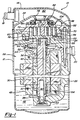
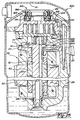
- Figure 1 is a vertical sectional view through the center of a scroll compressor which incorporates a first embodiment of the present invention;
- Figure 2 is a top elevational view of the compressor shown in Figure 1 with the cap and partition removed;
- Figure 3 is a fragmentary enlarged view of a portion of the floating seal illustrated in Figure 1;
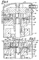
- Figure 4 is a vertical section through the upper portion of a scroll compressor which incorporates another embodiment of the present invention;
- Figure 5 is a vertical section through the upper portion of a scroll compressor which incorporates another embodiment of the present invention;
- Figure 6 is a vertical section through the upper portion of a scroll compressor which incorporates another embodiment of the present invention;
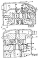
- Figure 7 is a vertical section through the center of a scroll compressor which utilizes the compressor motor as a solenoid valve;
- Figure 8 is a vertical section through the upper portion of a scroll compressor which utilizes the compressor motor as a solenoid valve according to another embodiment of the present invention;
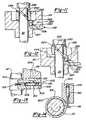
- Figure 9 is a schematic of a vertical section through the upper portion of a scroll compressor which utilizes a centrifugal valve for releasing intermediate pressure;
- Figure 10 is an enlarged sectional view of the centrifugal valve shown in Figure 9 shown in the closed position;
- Figure 11 is a schematic view of a vertical section through the center of a scroll compressor which utilizes angular acceleration of a component of the compressor to activate a valve (shown in the closed position) which releases intermediate pressure;
- Figure 12 is a schematic view of a vertical section through the center of a scroll compressor which utilizes angular acceleration of a component of the compressor to activate a valve (shown in the open position) which releases intermediate pressure;
- Figure 13 is a schematic view of a vertical section through the center of a scroll compressor which utilizes viscous drag of a component of the compressor to activate a valve, shown in the closed position, which releases intermediate pressure;
- Figure 14 is a horizontal sectional view through the crankshaft and collar shown in Figure 13;
- Figure 15 is a schematic view of a fail safe device for a solenoid valve shown in a first position;
- Figure 16 is a schematic view of a fail safe device for a solenoid valve shown in a second position;
- Figure 17 is a schematic view of a fail safe device for a solenoid valve shown in a third position;
- Figure 18 is a schematic of a thermal valve, shown in the closed position, for releasing intermediate pressure to the suction area of the compressor; and
- Figure 19 is a schematic of a thermal valve, shown in the open position, for releasing intermediate pressure to the suction area of the compressor.
- Figure 20 is a vertical sectional view through the center of a scroll compressor which incorporates an additional embodiment of the present invention;
- Figure 21 is a top elevational view of the compressor shown in Figure 20 with the cap and partition removed;
- Figure 22 is a fragmentary enlarged view of a portion of the floating seal illustrated in Figure 20;
- Figure 23 is a vertical section through the upper portion of a scroll compressor which incorporates another embodiment of the present invention;
- Figure 23A is an enlarged view of the area identified by
circle 23A in Figure 23; - Figure 24 is a vertical section through the upper portion of a scroll compressor which incorporates another embodiment of the present invention; and
- Figure 25 is a vertical section through the center of a scroll compressor which utilizes the compressor motor as a solenoid valve.
- While the present invention is suitable for incorporation in many different types of scroll machines, for exemplary purposes it will be described herein incorporated in a scroll refrigerant compressor of the general structure illustrated in Figure 1. Referring now the drawings and in particular to Figure 1, a
compressor 10 is shown which comprises a generally cylindricalhermetic shell 12 having welded at the upper end thereof acap 14.Cap 14 is provided with arefrigerant discharge fitting 18 which may have the usual discharge valve therein (not shown). Other major elements affixed to the shell include an inlet fitting 20, a transversely extendingpartition 22 which is welded about its periphery at the same point thatcap 14 is welded toshell 12, a two piece main bearinghousing 24 and a lower bearinghousing 26 having a plurality of radially outwardly extending legs each of which is suitably secured toshell 12. Lower bearinghousing 26 locates and supports withinshell 12 two piece main bearinghousing 24 and amotor 28 which includes amotor stator 30. A drive shaft orcrankshaft 32 having aneccentric crank pin 34 at the upper end thereof is rotatably journaled in abearing 36 in main bearinghousing 24 and a second bearing 38 in lower bearinghousing 26.Crankshaft 32 has at the lower end a relatively large diameterconcentric bore 40 which communicates with a radially outwardly inclinedsmaller diameter bore 42 extending upwardly therefrom to the top ofcrankshaft 32. Disposed withinbore 40 is astirrer 44. The lower portion of theinterior shell 12 defines anoil sump 46 which is filled with lubricating oil. Bore 40 acts as a pump to pump lubricating fluid up thecrankshaft 32 and intobore 42 and ultimately to all of the various portions of the compressor which require lubrication. -
Crankshaft 32 is rotatively driven byelectric motor 28 includingmotor stator 30,windings 48 passing therethrough and amotor rotor 50 press fitted oncrankshaft 32 and having upper andlower counterweights - The upper surface of two piece main bearing
housing 24 is provided with a flatthrust bearing surface 56 on which is disposed an orbitingscroll 58 having the usual spiral vane orwrap 60 on the upper surface thereof. Projecting downwardly from the lower surface of orbitingscroll 58 is a cylindrical hub having a journal bearing 62 therein and in which is rotatively disposed a drive bushing 64 having aninner bore 66 in whichcrank pin 34 is drivingly disposed.Crank pin 34 has a flat on one surface which drivingly engages a flat surface (not shown) formed in a portion ofbore 66 to provide a radially compliant driving arrangement, such as shown in assignee's U.S. Letters Patent 4,877,382, the disclosure of which is hereby incorporated herein by reference. AnOldham coupling 68 is also provided positioned between orbitingscroll 58 and bearinghousing 24.Oldham coupling 68 is keyed to orbitingscroll 58 and anon-orbiting scroll 70 to prevent rotational movement of orbitingscroll member 58.Oldham coupling 68 is preferably of the type disclosed in assignee's copending application Serial No. 591,443, entitled "Oldham Coupling For Scroll Compressor" filed October 1, 1990, the disclosure of which is hereby incorporated herein by reference. -
Non-orbiting scroll member 70 is also provided having awrap 72 positioned in meshing engagement withwrap 60 of orbitingscroll 58.Non-orbiting scroll 70 has a centrally disposeddischarge passage 74 which communicates with an upwardlyopen recess 76 which in turn is in fluid communication via anopening 78 inpartition 22 with adischarge muffler chamber 80 defined bycap 14 andpartition 22. The entrance to opening 78 has anannular seat portion 82 therearound.Non-orbiting scroll member 70 has in the upper surface thereof anannular recess 84 having parallel coaxial sidewalls in which is sealingly disposed for relative axial movement an annular floatingseal 86 which serves to isolate the bottom ofrecess 84 from the presence of gas under suction pressure at 88 and discharge pressure at 90 so that it can be placed in fluid communication with a source of intermediate fluid pressure by means of apassageway 92.Non-orbiting scroll member 70 is thus axially biased against orbitingscroll member 58 to enhance wrap tip sealing by the forces created by discharge pressure acting on the central portion ofscroll member 70 and those created by intermediate fluid pressure acting on the bottom ofrecess 84. Discharge gas inrecess 76 andopening 78 is also sealed from gas at suction pressure in the shell by means ofseal 86 acting againstseat portion 82. This axial pressure biasing and the functioning of floatingseal 86 are disclosed in greater detail in applicant's assignee's U.S. Letters Patent No. 5,156,539, the disclosure of which is hereby incorporated herein by reference.Non-orbiting scroll member 70 is designed to be mounted to bearinghousing 24 in a suitable manner which will provide limited axial (and no rotational) movement ofnon-orbiting scroll member 70.Non-orbiting scroll member 70 may be mounted in the manner disclosed in the aforementioned U.S. Patent No. 4,877,382 or U.S. Patent No. 5,102,316, the disclosure of which is hereby incorporated herein by reference. - The compressor is preferably of the "low side" type in which suction gas entering via fitting 20 is allowed, in part, to escape into the shell and assist in cooling the motor. So long as there is an adequate flow of returning suction gas the motor will remain within desired temperature limits. When this flow ceases, however, the loss of cooling will cause a
motor protector 94 to trip and shut the machine down. - The scroll compressor as thus far broadly described is either now known in the art or is the subject of other pending applications for patent or patents of applicant's assignee.
- As noted, both of the primary embodiments of the present invention utilize a very simple valve which functions at compressor shut down to allow gas flow from an area of intermediate pressure to an area of suction pressure. The valve of the present invention operates to allow gas at intermediate pressure to flow to an area of suction pressure which then allows discharge pressure to dump to suction pressure. By working with gas at intermediate pressure rather than directly with gas at discharge temperature, the size, complexity and cost of the valve can be significantly reduced. In the first set of embodiments, the valve is operated by a solenoid, and in the second set of embodiments, the valve is run by a mechanical device. It is believed that all primary embodiments of the present invention are fully applicable to any type of scroll compressor.
- The first embodiment of the present invention is shown in Figures 1 through 3. The first embodiment makes use of the dual pressure balancing scheme described above which is used to axially balance
non-orbiting scroll member 70 with floatingseal 86 being used to separate the discharge gas pressure from the suction gas pressure. - A
solenoid valve 98 comprises asolenoid 100 and avalve 102.Solenoid valve 98 can be wired in parallel or in series withmotor 28 such thatsolenoid 100 is activated and deactivated withmotor 28 orsolenoid valve 98 may be wired independently frommotor 28. When solenoidvalve 98 is wired independently frommotor 28,valve 98 may be operated in a pulsed manner or a pulsed width modulated manner to modulate the capacity ofcompressor 10.Solenoid 100 is operable to open andclose valve 102 which is in communication with apassageway 104 located withinnon-orbiting scroll 70.Passageway 104 extends from the bottom ofrecess 84 which is at intermediate pressure during operation of the compressor to the area of the compressor which contains suction gas at suction gas pressure. -
Solenoid 100 andvalve 102 are best shown in Figure 2.Solenoid 100 includes acylindrical wire coil 106 surrounding aplunger 108 in the usual manner.Solenoid 100 is secured tovalve 102 by any method known well in the art.Valve 102 includes avalve body 110 having apassageway 112 which is in communication withpassageway 104 innon-orbiting scroll 70.Valve body 112 is attached tonon-orbiting scroll 70 by methods known well in the art. Aball 114 is disposed withinpassageway 112 and moveable between an open position and a closed position due to the movement ofplunger 108. In its open position, fluid is allowed to flow frompassageway 104 throughpassageway 112. In its closed position fluid is prohibited from flowing throughpassageways ball 114 being forced against avalve seat 116 located withinpassageway 112 byplunger 108. - At compressor start-up,
solenoid 100 is energized andvalve 102 is closed to block any fluid flow throughpassageway 104. In this manner,compressor 10 makes a normal start-up. In some designs of compressors, compression within the scrolls builds rapidly at start-up. This build up of pressure can be so rapid in fact that the compressor may stall because of insufficient motor torque. Generally, this is only a problem when using single phase motors. When this build up of pressure occurs, the motor stalls and the motor protector repeatedly trips and the compressor has a difficult time starting again. An option in the present invention is to build in a time delay to the activation ofsolenoid 100 to prevent the closing ofpassageway 104 at start-up, thus keeping intermediate pressure from building up. This lack of intermediate pressure will allow the scrolls to separate axially and prevent compression build-up until sufficient motor torque has been generated. - At compressor shut-down,
solenoid 100 is de-energized at the same instant that power tomotor 28 is cut off. The de-energization ofsolenoid 100 causesvalve 102 to open and allows fluid flow throughpassageways recess 84 to the suction area ofcompressor 10. As the intermediate pressure and suction pressure become equalized, floatingseal 86 has a net downward force due to the discharge gas pressure and floatingseal 86 moves downward inrecess 84 and creates a discharge gas to suction gas leak across the top of floatingseal 86 atannular seat portion 82. By controlling the size ofpassageway 104 and/orpassageway 112, reverse rotation can be minimized to any acceptable reverse RPM or it can be completely eliminated. -
Solenoid valve 98 may be an AC (alternating current) or a DC (direct current) solenoid independent of the type ofmotor 28. If a DC solenoid is to be used with an AC motor, a rectifier needs to be wired between the AC power source and the DC solenoid. - Figure 4 shows another embodiment of the present invention. In Figure 4, elements which are the same as those in Figures 1 through 3 have been given the same reference numerals. The embodiment in Figures 1 through 3 purges intermediate pressure within
recess 84 which holdsnon-orbiting scroll 70 down allowing floatingseal 86 to drop. The embodiment shown in Figure 4 is incorporated into a compressor which uses intermediate pressure to bias orbitingscroll 58 upward. The embodiment shown in Figure 4 purges the intermediate pressure holding orbitingscroll 58 up which then creates sufficient tip clearance between the tips of scroll wraps 60 and 72 and their respective mating scroll to allow high pressure discharge gas to leak back throughscrolls - Figure 4 shows the upper section of a
compressor 130.Compressor 130 is similar tocompressor 10 with the exception thatpartition 22 ofcompressor 10 has been eliminated along with floatingseal 86. In order to separate the discharge gas from the suction gas area, non-orbiting, or in this case, stationary, scroll 70 extends completely acrossshell 12 andcap 14. Bothshell 12 andcap 14 are secured tonon-orbiting scroll 70 by welding or other means known well in the art. -
Main bearing housing 24 is provided with anannular chamber 132 extending into flatthrust bearing surface 56. A firstannular seal 134 is positioned radially outward fromchamber 132 and a secondannular seal 136 is positioned radially inward fromchamber 132.Seals chamber 132 to the suction side ofcompressor 130. Apassageway 138 extends through orbitingscroll 58 and fluidically connectschamber 132 to an area of intermediate pressure withincompressor 130. During operation ofcompressor 130, fluid at an intermediate pressure is supplied tochamber 132 throughpassageway 138. Orbitingscroll 58 is thus forced axially upward due to the fluid pressure withinchamber 132. The fluid pressure withinchamber 132 is maintained byseals -
Compressor 130 further includes apassageway 140 extending throughmain bearing housing 24 and connectingchamber 132 tosolenoid valve 98. The embodiment shown in Figure 4 includes afluid tube 142 extending frompassageway 140 tosolenoid valve 98 which will allow the placement ofsolenoid valve 98 anywhere within the suction area ofcompressor 130 as space will permit. It will be appreciated that the use oftube 142 or its equivalent may be used with any of the embodiments of the present invention to facilitate packaging and design requirements. It is also possible to havetube 142 extend throughshell 12 and havesolenoid 100 andvalve 102 located externally to shell 12 if desired. - The operation of the embodiment shown in Figure 4 is similar to the operation of the embodiment shown in Figures 1 through 3. At compressor start-up,
solenoid 100 is energized andvalve 102 is closed to block any fluid flow frompassageway 140 throughpassageway 112. In thisway compressor 130 makes a normal start-up. The time delay feature at compressor start-up described above may also be built intosolenoid valve 98 for this embodiment. At compressor shut-down,solenoid 100 is de-energized causingvalve 102 to open and allow fluid flow throughpassageways chamber 132 to the suction area ofcompressor 130. As the intermediate pressure and suction pressure are equalized, orbitingscroll 58 moves downward and creates a discharge gas to suction gas leak across the tips of scroll wraps 60 and 72. The amount of reverse rotation can be controlled by controlling the size ofpassageway 140 and/orpassageway 112. The de-energization ofvalve 102 and the shutdown ofmotor 28 may also be tied in with a time delay to insure that sufficient leakage betweenchamber 132 and the suction area of the compressor has occurred before the motor is shut down. It is to be appreciated that this time delay feature at the shut down of the compressor can be applied to any of the embodiments of the present invention which incorporatesolenoid valve 98. - Figures 5 and 6 show another embodiment of the present invention. The embodiment shown in Figures 1 through 3 and the embodiment shown in Figure 4 utilize the purging of intermediate pressure from an existing chamber in the compressor which is being utilized to bias one of the scroll members towards the other. The effect of purging this intermediate pressure from a biasing chamber is to create a leak between existing compressor components which then allows the discharge gas pressure and suction gas pressure to equalize. In some cases, it may be desirable to create a direct path for the discharge pressure to equalize with the suction pressure rather than relying on the movement or separation of various components of the compressor.
- The embodiment shown in Figures 5 and 6 include a pressure ratio sensitive valve which directly bypasses discharge pressure to suction pressure. Figure 5 shows a
compressor 150 having a pressure ratiosensitive valve 152 incorporated into orbitingscroll 58. The design ofcompressor 150 in Figure 5 is similar to the design ofcompressor 130 shown in Figure 4 in thatnon-orbiting scroll 70 is a fixed scroll attached to shell 12 andcap 14.Main bearing housing 24 is provided withannular chamber 132 extending into flatthrust bearing surface 56.Seals chamber 132 to the suction side ofcompressor 150.Passageway 138 extends through orbitingscroll 58 and connectschamber 132 to an area of intermediate pressure withincompressor 150. During operation ofcompressor 130, fluid at an intermediate pressure is supplied tochamber 132 throughpassageway 138. Orbitingscroll 58 is thus biased axially upward due to the fluid pressure withinchamber 132. The fluid pressure withinchamber 132 is maintained byseals - The embodiment shown in Figure 5 includes a
passageway 140 extending throughmain bearing housing 24 and connectingchamber 132 tosolenoid valve 98. The embodiment shown in Figure 5 includesfluid tube 142 extending frompassageway 140 which will allow the placement ofsolenoid valve 98 anywhere within the suction area ofcompressor 150 as space will permit. Up to this point,compressor 150 shown in Figure 5 is the same ascompressor 130 shown in Figure 4 and the operation ofcompressor 150 is the same as the operation ofcompressor 130 as described above. -
Compressor 150 further includes pressure ratiosensitive valve 152 disposed within apocket 154 located within orbitingscroll 58. Adischarge pressure passageway 156 extends betweendischarge passageway 74 andpocket 154. Asuction pressure passageway 158 extends betweenpocket 154 and the suction area ofcompressor 150. Avalve body 160 is disposed withinpocket 154 and is axially movable withinpocket 154 to allow or prohibit fluid flow betweenpassageway 156 andpassageway 158.Valve body 160 andpocket 154 are designed such thatvalve body 160 is capable of axial movement withinpocket 154 but fluid flow betweenvalve body 160 andpocket 154 is prohibited. The upper surface ofvalve body 160 has anannular ring 162 which separates the area abovevalve body 160 into anannular chamber 164 and acylindrical chamber 166. - The operation of the embodiment shown in Figure 5 is similar to the operation of
compressor 130 shown in Figure 4. At compressor start-up,solenoid 100 is energized andvalve 102 is closed to block any fluid flow frompassageway 140 throughpassageway 112. In thisway compressor 150 makes a normal start-up. The time delay feature for compressor start-up may also be built intosolenoid valve 98 for this embodiment. Whilecompressor 150 is in operation, the position ofvalve body 160 is determined by the various pressures operating against respective surface areas ofvalve body 160. Intermediate pressure withinchamber 132 exerts an upward force onvalve body 160 equal to the amount of intermediate pressure times the surface area ofvalve body 160 exposed tochamber 132. Discharge pressure is being supplied toannular chamber 164 and thus exerts a downward force onvalve body 160 equal to the amount of discharge pressure times the surface area ofvalve body 160 exposed tochamber 164. In a similar manner, suction pressure is being supplied tocylindrical chamber 166 and thus exerts a downward force onvalve body 160 equal to the amount of suction pressure times the surface area ofvalve body 160 exposed tochamber 166. Thus, the opening and closing of pressure ratiosensitive valve 152 can be controlled by selecting the size ofvalve body 160 and the size and diameter ofannular ring 162 to control the various surface areas. - At compressor shutdown,
solenoid 100 is de-energized causingvalve 102 to open and allow fluid flow throughpassageway chamber 132 to the suction area ofcompressor 150. As the intermediate pressure and suction pressure are equalized, both orbitingscroll 58 andvalve body 160 are moved downward. The movement ofscroll 58 causes a discharge gas to suction gas leak across the tips of scroll wraps 60 and 72 as explained above for the embodiment shown in Figure 4. In addition, the movement ofvalve body 160 withinpocket 154 allows discharge gas to flow frompassageway 156 throughpassageway 158 thus creating a direct fluid flow between the discharge gas and the suction gas. The various controls including the size ofpassageway 140 and/orpassageway 112 and the time delay at compressor shut down described above for the embodiment shown in Figure 4 are also applicable to this embodiment. In addition, the amount of reverse rotation can be further controlled by the size ofpassageways valve body 160. - Figure 6 shows another embodiment of the present invention. Figure 6 shows a
compressor 180 having a pressure ratiosensitive valve 182 disposed within a pocket located within non-orbiting or fixedscroll 70. Similar to the embodiment shown in Figures 1 through 3,compressor 180 includes fixedscroll 70, orbitingscroll 58,shell 12,cap 14 andpartition 22.Compressor 180 has fixedscroll 70 bolted directly to partition 22 by a plurality ofbolts 184. Because non-orbiting or fixedscroll 70 does not move axially as in Figures 1 through 3, the need for floatingseal 86 has been eliminated.Compressor 180 may or may not utilize biasingchamber 132 located withinmain bearing housing 24 in conjunction withseals bias orbiting scroll 58 towards fixedscroll 70 in a manner similar to that described for the embodiment shown in Figure 4 but not shown in Figure 6. -
Compressor 180 includes pressure ratiosensitive valve 182 disposed within apocket 186 located withinfixed scroll 70. Anintermediate pressure passageway 188 extends between an intermediate pressure zone withincompressor 180 andpocket 186. Avent passageway 190 extends betweenpocket 186 and the inlet tosolenoid valve 98.Solenoid valve 98 may be attached directly to fixedscroll 70 as shown in Figure 1 or it may be located remotely from fixedscroll 70 by usingtube 142 as shown in Figures 4 and 6. Avalve body 192 is disposed withinpocket 186 and is axially movable withinpocket 186 to allow or prohibit fluid flow through anorifice 194 extending throughpartition 22.Valve body 192 andpocket 186 are designed such thatvalve body 192 is capable of axial movement withinpocket 186 but fluid flow betweenvalve body 192 andpocket 186 is prohibited by slidingseal 196. The upper surface ofvalve body 192 has acylindrical extension 198 which is adapted with avalve seat 200 for sealingorifice 194. - The operation of the embodiment shown in Figure 6 is similar to the operation of
compressor 150 shown in Figure 5. At compressor start-up,solenoid 100 is energized andvalve 102 is closed to block any fluid flow frompassageway 190 throughpassageway 112. In this way,compressor 180 makes a normal start-up. The time delay feature for compressor start-up may also be built intosolenoid valve 98 for this embodiment. Whilecompressor 180 is in operation, the position ofvalve body 192 is determined by the various pressures operating against respective surface areas ofvalve body 192. Intermediate pressure withinpocket 186 exerts an upward force onvalve body 192 equal to the amount of intermediate pressure times the surface area of thevalve body 192. Discharge pressure is being supplied toorifice 194 and thus exerts a downward force onvalve body 192 equal to the amount of discharge pressure times the area oforifice 194. In a similar manner, suction pressure is present at the upper end ofpocket 186 and thus exerts a downward force onvalve body 192 equal to the amount of suction pressure times the surface area ofvalve body 192 minus the surface area oforifice 194. Thus the opening and closing of pressure ratiosensitive valve 182 can be controlled by selecting the size ofvalve body 192 and the size oforifice 194. - At compressor shutdown,
solenoid 100 is de-energized causingvalve 102 to open and allow fluid flow throughpassageways pocket 186 to the suction area ofcompressor 180. As the intermediate pressure and suction pressure are equalized,valve body 192 moves downward due to discharge pressure atorifice 194. The movement ofvalve body 192 withinpocket 186 creates a direct fluid flow between the discharge gas and the suction gas throughorifice 194. The various controls including the size ofpassageway 190 and/orpassageway 112 and the time delay at compressor shut down described for the embodiment in Figure 4 are also applicable to this embodiment. In addition, the amount of reverse rotation can be further controlled by the size oforifice 194 in relationship to the size ofvalve body 192 as described above. - Figures 7 and 8 show another embodiment of the present invention. Figures 7 and 8 eliminate the need for
solenoid valve 98. Rather than usingsolenoid valve 98, the compressor shown in Figures 7 and 8 utilizemotor 28 andcrankshaft 32 to perform the switching function ofsolenoid valve 98. A solenoid is basically a wire coil which generates a magnetic field, which in turn pushes or pulls a plunger within the coil. This is very similar to the compressor motor.Motor stator 30 creates a rotating magnetic filed which tends to axiallycenter motor rotor 50 withinmotor stator 30. The embodiment shown in Figures 7 and 8 use this centering force in conjunction with an opposing spring force to create the same result as a solenoid. - Figure 7 shows
compressor 220 which is similar tocompressor 10 shown in Figure 1 except thatsolenoid valve 98 has been replaced bytube 142 and avalve 222 which usesmotor 28 andcrankshaft 32 for opening and closing.Passageway 104 extends throughnon-orbiting scroll 70 and is sealingly secured totube 142.Tube 142 is routed throughcompressor 220 and its opposite end is sealingly secured to apassageway 224 extending throughmain bearing housing 24.Passageway 224 extends from one side ofmain bearing housing 24 to anupper surface 226 where it is open to the suction area ofcompressor 220.Crankshaft 32 extends throughmain bearing housing 24 and has anannular sealing flange 228 attached to crankshaft 32 at a position adjacent toupper surface 226. In the embodiment shown in Figure 7,flange 228 is shown integral withcrankshaft 32 andupper counterweight 52 is attached toflange 228. It is within the scope of the present invention to haveflange 228 andcounterweight 52 formed as one piece and attached tocrankshaft 32 if desired.Crankshaft 32 is normally biased upward by a biasingspring 230 positioned between lower bearinghousing 26 andcrankshaft 32 such that sealingflange 228 is biased away fromupper surface 226 andpassageway 224 is open to the suction area ofcompressor 220. - At compressor start-up,
crankshaft 32 is forced downward against the load of biasingspring 230 due to the centering force created by the magnetic field ofmotor 28 which tends to axiallycenter motor rotor 50 and thus crankshaft 32 withinmotor stator 30. This downward movement ofcrankshaft 32 brings intocontact sealing flange 228 andupper surface 226 which prohibits fluid flow throughpassageway 224. In this manner,compressor 220 makes a normal start-up. - At compressor shut-down, power to
motor 28 is cut off eliminating the magnetic field which tends to centermotor rotor 50 withinmotor stator 30.Crankshaft 32 is once again biased upwards byspring 230separating sealing flange 228 fromupper surface 226 andopening passageway 224 to the suction area ofcompressor 220. The fluid flow frompassageway 104, throughtube 142 and throughpassageway 224 allows fluid flow from the bottom ofchamber 84 to the suction area ofcompressor 220. As the intermediate pressure and suction pressure are equalized, floatingseal 86 has a net downward force due to the discharge gas pressure and a discharge gas to suction gas leak is created identical to that described for Figure 1. - Figure 8 shows another embodiment of the present invention which is similar to the embodiment in Figure 4 but utilizes
motor 28 andcrankshaft 32 as the valve similar to that described above for Figure 7. Figure 8 shows acompressor 240 which includes an intermediate gaspressure basing chamber 132 similar to that shown in Figure 4.Compressor 240 also includes apassageway 242 which extends from ahorizontal surface 244 on bearinghousing 24 to meet apassageway 246 extending from biasingchamber 132. - The operation of
compressor 240 is identical to the operation ofcompressor 220 described above except that the intermediate pressure is released from below the orbiting scroll rather than from below floatingseat 86 and the discharge gas to suction gas leak is created identical to that described in Figure 4. In addition, it should be appreciated that a pressure ratio sensitive valve as described in the embodiments shown in Figures 5 and 6 may also be incorporated intocompressor 240 if desired. - Figures 9 and 10 show another embodiment of the present invention. The embodiment shown in Figures 9 and 10 makes use of centrifugal force to activate a valve above a predetermined rotational speed. This valve is biased to an open position at low speed allowing the purging of the intermediate pressure gas. It is to be appreciated that this centrifugal valve can be utilized with any of the embodiments described above whereby the centrifugal valve replaces the solenoid valve.
- Figures 9 and 10 show a
compressor 250 which incorporates acentrifugal valve 252 to replacesolenoid valve 98.Centrifugal valve 252 as best shown in Figure 10 includes avalve body 254 secured to crankshaft 32 for rotation therewith but capable of axial movement alongcrankshaft 32. Avalve spring 256biases valve body 254 axially alongcrankshaft 32 and sealingly engagesvalve body 254 withmain bearing housing 24. Afirst passageway 258 extends radially throughvalve body 254. Avalve 260 is slidingly received withinpassageway 258 and is biased radially inward by acoil spring 262. The radial outward end ofpassageway 258 is closed by aball 264 which also provides for a reaction point forcoil spring 262. - The upper surface of
valve body 254 which is opposite tovalve spring 256 is provided with anannular groove 266 which is in communication withpassageway 224 inmain bearing housing 24. Anaxial passageway 268 extends fromannular groove 266 throughradial passageway 258 and into the suction area ofcompressor 250. When coilspring biases valve 260 radially inward,passageway 224 is open to the suction area ofcompressor 250 throughgroove 266 andaxial passageway 268. When centrifugal force urgesvalve 260 radially outward against the load ofcoil spring 262,valve 260 will blockaxial passageway 268 and prohibit fluid flow frompassageway 224 to the suction area ofcompressor 250. - At compressor start-up,
valve 260 is biased radially inward bycoil spring 262. As the rotational speed ofcrankshaft 32 andcentrifugal valve 252 increases,valve 260 is forced radially outward to blockaxial passageway 268. In this manner,compressor 250 makes a normal start-up. - At compressor shutdown,
valve 260 will remain in a position to blockaxial passageway 268 until such a time that the load exerted bycoil spring 262 exceeds the centrifugal force exerted onvalve 260 as the rotational speed ofcentrifugal valve 252 decreases. Eventuallyvalve 260 will move sufficiently inward to openaxial passageway 268 and the intermediate pressure withinpassageway 224 will be purged to the suction area ofcompressor 250. The purging of the intermediate pressure to suction pressure has the identical effect as described above for the previous embodiments. The rate control for this embodiment would involve the size ofaxial passageway 268, the weight ofvalve 260 and the rate forcoil spring 262. - It is to be appreciated that the embodiment shown in Figures 9 and 10 can replace the solenoid valve in any of the various embodiments described above.
- Figures 11 and 12 show schematically another embodiment of the present invention. The embodiment shown in Figures 11 and 12 uses angular acceleration at start-up to block a vent hole, and deceleration at shutdown to unblock the vent hole and allow the purging of intermediate gas pressure to suction gas pressure. Figures 11 and 12 schematically represent the reverse rotation protection of this embodiment of the present invention and include
crankshaft 32,main bearing housing 24,passageway 224, avalve 280 and acollar 282. -
Valve 280 is located withinpassageway 224 at the point wherepassageway 224 extends throughupper surface 244.Valve 280 includes aball 284, anactivation device 286 and avalve seat 288.Collar 280 is slidingly received oncrankshaft 32 at a position adjacent toupper surface 244 onmain bearing housing 24.Collar 282 includes apin 290 which extends throughcollar 282 and is disposed in aspiral groove 292 located incrankshaft 32. Acoil spring 294biases collar 282 downward towardsupper surface 244 onmain bearing housing 24. In the lower position shown in Figure 11,collar 282contacts activation device 286 which inturn forces ball 284 againstvalve seat 288 to prohibit movement of fluid throughpassageway 224. Whencollar 282 is moved away fromupper surface 244 by relative movement ofcollar 282 oncrankshaft 32 as shown in Figure 12, the intermediate pressure acting againstball 284forces ball 284upward opening passageway 224 to the suction area of the compressor. - At compressor start-up, as shown in Figure 11, positive angular acceleration of
crankshaft 32 causes relative movement betweencrankshaft 32 andcollar 282 due to the inertial effects oncollar 282. The direction ofspiral groove 292 is such that this positive angular acceleration ofcrankshaft 32 causespin 290 to move downward ingroove 292 forcingcollar 282 againstupper surface 226 and closingvalve 280 by forcingball 284 againstvalve seat 288. In this manner, the compressor makes a normal start-up. - At compressor shut-down, as shown in Figure 12, the opposite is true. A negative angular acceleration of
crankshaft 32 causes relative movement betweencrankshaft 32 andcollar 282 again due to the inertial effects oncollar 282. The direction ofspiral groove 292 now causespin 290 to move upward ingroove 292 due to this negative angular acceleration. Aspin 290 moves upward ingroove 292,collar 282 is moved away fromface 244 and the intermediate pressure beneathball 284forces ball 284 off ofvalve seat 288 andpassageway 224 is open to the suction area of the compressor allowing the purging of the intermediate pressure. - It is to be appreciated that the embodiment shown in Figures 11 and 12 can replace the solenoid valve in any of the various embodiments described above.
- Figures 13 and 14 show another embodiment of the present invention. The embodiment shown in Figures 13 and 14 uses a viscous drag caused by a rotating component of the compressor. In Figures 13 and 14, the rotating component shown is
crankshaft 32, although any rotating component within the compressor could be used. Viscous drag caused by a rotating component can generate sufficient force to rotate a spring loaded device into a position to block a vent hole or to actuate a valve. Figures 13 and 14 schematically represent the reverse rotation protection of this embodiment of the present invention and includecrankshaft 32, acollar 300 and avalve 302.Valve 302 includes avalve body 304, avalve spring 306, afirst passageway 308, avalve 310 and asecond passageway 312. -
Collar 300 is slidingly received oncrankshaft 32 as shown in Figures 13 and 14. The relationship between the outside diameter ofcrankshaft 32 and the inside diameter ofcollar 300 is such that aviscous fluid film 314 exists betweencrankshaft 32 andcollar 300. Whencollar 300 is prohibited from rotating withcrankshaft 32, the rotating ofcrankshaft 32 attempts to shearviscous fluid film 314 between the two components. This shearing of the viscous fluid will cause a torque to be applied tocollar 300 asviscous fluid film 314 attempts to rotatecollar 300 withcrankshaft 32.Collar 300 is provided with aradially extending paddle 316 which is used to activatevalve 302 as will be described later herein. -
Valve body 304 may be secured tomain bearing housing 24 similar to the attachment ofvalve 104 tonon-orbiting scroll 70 shown in Figures 1 through 3 orvalve body 304 may be separate from main bearing housing and provided with intermediate pressure bytube 142. -
First passageway 308 extends longitudinally throughvalve body 304.Valve 310 is slidingly received withinpassageway 308 and is biased towardspaddle 316 ofcollar 300 as shown in Figure 13 byvalve spring 306. The end ofpassageway 308 opposite tovalve 310 is closed by aball 318 which also provide for a reaction point forvalve spring 306. -
Second passageway 312 extends throughvalve body 304 and throughfirst passageway 308 generally perpendicular tofirst passageway 308. One end ofsecond passageway 312 is connected to the source of intermediate pressure either directly throughpassageway 224 or throughtube 142. The opposite end ofsecond passageway 312 is open to the suction area of the compressor. Whenvalve spring 306biases valve 310 towardspaddle 316,second passageway 312 is open and the source of intermediate pressure is open to the suction area of the compressor. When torque is applied tocollar 300, due to the viscous drag, paddle 316 exerts a load onvalve 310 which overcomes the force ofvalve spring 306 and movesvalve 310 to a position which blockssecond passageway 312 and prohibits the source of intermediate pressure from purging to the suction area of the compressor. - At compressor start-up,
valve 310 is biased towardspaddle 316 byvalve spring 306. As the rotational speed difference betweencrankshaft 32 andcollar 300 increases, the torque exerted oncollar 300 increases due to the shear ofviscous fluid film 314 betweencrankshaft 32 andcollar 300. The rotation ofcollar 300 withcrankshaft 32 is prohibited bypaddle 316 contactingvalve 310. As the torque oncollar 300 increases, the load onvalve 310 increases andvalve 310 is forced longitudinally withinfirst passageway 308 againstvalve spring 306 to blocksecond passageway 312. In this manner,compressor 250 makes a normal start-up. - At compressor shutdown,
valve 310 will remain in a position to blocksecond passageway 312 until such a time that the load exerted byvalve spring 306 exceeds the load exerted bypaddle 316 onvalve 310 as the rotational speed difference betweencrankshaft 32 andcollar 300 decreases. Eventuallyvalve 310 will move sufficiently inward to opensecond passageway 312 and the source of intermediate pressure will be purged to the suction area of the compressor. The purging of the intermediate pressure in this embodiment has the identical effect as described for the previous embodiments. The rate control for this embodiment would include the size ofsecond passageway 312, the rate forvalve spring 306 and the width offluid film 314. - It is to be appreciated that the embodiment shown in Figures 13 and 14 can replace the solenoid valve in any of the various embodiments described above.
- Figures 15 through 17 illustrate schematically a fail-safe device which may be incorporated into a
solenoid valve 350 which would be a replacement forsolenoid valve 98 of the previous embodiments.Solenoid valve 350 operates similar to the operation ofsolenoid valve 98.Solenoid valve 98, when energized, pushesball 114 ontovalve seat 116 to prohibit fluid flow throughpassageway 112.Solenoid valve 350, when energized, moves away from a ball to allow the ball to seat on a valve seat. Whensolenoid valve 350 is de-energized it pushes the ball off of the valve seat to allow fluid flow through the valve. - Figures 15 through 17 schematically illustrate
solenoid valve 350 which includes asolenoid 352, adashpot 354 and avalve 356.Solenoid 352 comprises acylindrical wire coil 358, surrounding aplunger 360 in the usual manner. Areturn spring 362 forces plunger 360 towards the left as shown in Figure 15.Dashpot 354 comprises anouter housing 364 which is fixedly secured toplunger 360, aninner housing 366, and adashpot spring 368.Inner housing 366 is slidingly received within apocket 370 located withinouter housing 364.Dashpot spring 368 is disposed withinpocket 370 and urgesinner housing 366 to the left as shown in Figure 15.Inner housing 366 includes anactuation pin 372 which extends fromhousing 366 towardsvalve 356 for opening and closingvalve 356 as will be described later herein.Valve 356 comprises avalve body 374, aball 376 and avalve spring 378.Valve body 374 includes abore 380 extending longitudinally withinvalve body 374.Ball 376 is disposed withinbore 380 and is urged to the right as shown in Figure 15 against avalve seat 382 byvalve spring 378. The source of intermediate pressure is supplied to bore 380 either directly or bytube 142. - The operation of
solenoid valve 350 begins withsolenoid 352 being de-energized,dashpot 354 being collapsed andvalve 356 being closed due tovalve spring 378urging ball 376 againstvalve seat 382. This position is illustrated schematically in Figure 15.Activation pin 372 is biased againstball 376 bydashpot spring 368 but it is not able to unseatball 376 due to the force exerted onball 376 byvalve spring 378. The rate ofvalve spring 378 is chosen to be higher than the rate ofdashpot spring 368. - At compressor start-up, as shown in Figure 16,
solenoid 352 is energized andplunger 360 is urged to the right as shown in Figure 16. This urgesouter housing 364 to the right also anddashpot 354 extends axially due to the load exerted bydashpot spring 368. This extension ofdashpot 354 maintains the contact betweenactivation pin 372 andball 376. In this manner, the compressor will have a normal start-up. - At compressor shut-down, as shown in Figure 17,
solenoid 352 is de-energized andplunger 360 is forced to the left as shown in Figure 17 due to returnspring 362. The movement to the left ofplunger 360 moves dashpot 354 to the left causingactivation pin 372 to unseatball 376 fromvalve seat 382.Valve spring 378 is unable to overcome the load exerted byactivation pin 372 due to the force being exerted byreturn spring 362 and the resistance to collapsing ofdashpot 354. The rate ofreturn spring 362 is chosen to be higher than the rate ofvalve spring 378.Ball 376 will remain unseated fromvalve seat 382 for a period of time defined by the design ofdashpot 354.Valve spring 378 will eventually work to collapsedashpot 354 andseat ball 376 againstvalve seat 382. This returnssolenoid valve 350 to the position shown in Figure 15. During the time thatball 376 is unseated fromvalve seat 382, the gas at intermediate pressure will be purged to the suction area of the compressor. The purging of the intermediate pressure in this embodiment has the identical effect as described for the previous embodiments. The rate control for this embodiment would include the size ofvalve seat 382, the rates forsprings dashpot 354. - The fail safe feature of
solenoid valve 350 works by allowingvalve 356 to remain seated ifplunger 360 fails to retract at start-up, fails to return at shut-down or is stuck in any other position for whatever reason. Ifdashpot 354 itself fails, in either the collapsed or extended position, the compressor will function in a normal manner albeit with a loud shut-down. - It is to be appreciated that the fail safe feature of the embodiment shown in Figures 15 through 17 can be incorporated into the solenoid valve in any of the various embodiments described above.
- Figures 18 and 19 show another embodiment of the present invention. In the previously detailed embodiments the purging of the intermediate pressurized gas to the suction area of the compressor was directly related to the start-up and shut-down of the compressor. The embodiment shown in Figures 18 and 19 uses a thermal switch to activate the purging of the source of intermediate pressurized gas to the suction area of the compressor. Once the thermal protector is switched, the dumping of the source of intermediate pressurized gas will allow discharge gas to leak to the suction area of the compressor as detailed above in the previous embodiments. The discharge gas to suction leak will lower the operating pressure ratio of the compressor and the discharge side temperature. Eventually the motor protector for the compressor will take the compressor off line due to high temperature discharge gas being leaked to the suction area of the compressor where the motor and motor protector are located.
- Figures 18 and 19 illustrate schematically the thermal responsive valve of the present invention which is generally designated by
reference numeral 400.Valve 400 comprises avalve body 402, afirst chamber 404, asecond chamber 406, adischarge pressure passageway 408 and asuction pressure passageway 410.Valve body 402 can be a separate component orvalve body 402 may be an integral part ofnon-orbiting scroll 70,main bearing housing 24 or any other component within the compressor. -
First chamber 404 extends intovalve body 402 and is placed in communication with the discharge gas of the compressor.Discharge pressure passageway 408 extends from the lower end ofchamber 404 and fluidically connectschamber 404 with the lower end ofchamber 406. A therm-o-disc (TOD) 410 is located on the step formed bychamber 404 andpassageway 408.TOD 410 remains seated prohibiting discharge gas flow fromchamber 404 topassageway 408. When a predetermined critical temperature is encountered,TOD 410 opens and allows full flow of discharge gas fromchamber 404 topassageway 408. -
Second chamber 406 is a stepped chamber also extending intovalve body 402. The upper or larger portion ofchamber 406 is placed in communication with the source of intermediate pressurized gas. The lower or smaller portion ofchamber 406 is placed in communication withchamber 404 throughpassageway 408.Suction pressure passageway 410 extends from a suction gas area within the compressor to the lower portion ofchamber 406. The point at whichsuction pressure passageway 410 enterschamber 406 is betweenhigh pressure passageway 408 and the upper or larger portion ofchamber 406. - A
flat check valve 412 having apiston 414 extending from it is disposed withinchamber 406.Flat check valve 412 andpiston 414 move together withinchamber 406 from a closed position as shown in Figure 18 to an open position as shown in Figure 19. Aretainer 416 limits the movement offlat check valve 412 andpiston 414 withinchamber 406. In its closed position, as shown in Figure 18,flat check valve 412 seats against the step formed inchamber 406 to prohibit fluid flow from the source of intermediate pressurized gas being supplied to the upper portion ofchamber 406 tosuction pressure passageway 410.Flat check valve 412 is forced downward due to the intermediate pressurized gas reacting on the exposed area of the step ofcheck valve 412 and suction gas pressure reacting on the exposed area ofpiston 414.Flat check valve 412 will be forced upward due to the discharge gas pressure acting againstpiston 414 whenTOD 410 is in the open condition. In its open position, as shown in Figure 19,flat check valve 412 is lifted from the stepped portion ofchamber 406 and gas at intermediate pressure is allowed to leak to the suction side of the compressor.Retainer 416 limits the movement offlat check valve 412 such that discharge gas withinpassageway 408 is not allowed to flow into the suction area of the compressor. - Thermal
responsive valve 400 is normally positioned as shown in Figure 18. Discharge gas is being supplied tochamber 404 and intermediate pressurized gas is being supplied tochamber 406. The compressor operates normally as long asTOD 410 remains closed. WhenTOD 410 experiences an over temperature condition of the discharge gas withinchamber 404,TOD 410 opens and allows discharge gas to enterpassageway 408. The pressure of the discharge gas reacts against the exposed surface area ofpiston 414 raisingflat check valve 412 which allows the source of intermediate pressurized gas in communication withchamber 406 to purge throughpassageway 410 and into the suction area of the compressor. This purging of the intermediate gas within the compressor allows a discharge gas to suction gas leak with the effects as described above for the various embodiments. Because the opening ofTOD 410 is not tied in with the shutting down of the motor of the compressor, the motor will continue to run with the compressor having a lower operating pressure ratio and a lower discharge side temperature. The motor will continue to run until the motor protector takes the compressor of line due to the high temperature discharge gas being leaked into the suction area of the compressor where the motor and motor protector are located. - Figures 20 through 22 illustrate another embodiment of the present invention. Figures 20 through 22 show a
compressor 500 which incorporates unique floatingseal basing means 510. The reference numerals shown in Figures 20 through 22 which are identical to those shown in Figures 1 through 3 respectably depict like or corresponding components in both figures.Compressor 500 incorporates biasing means 510 in order to be able to control the rate at which intermediate pressure is bled to suction pressure which will in turn control the rate at which discharge pressure is bled to suction pressure. It has been found that dumping the intermediate pressure too quickly will causecompressor 500 to coast and become noisy. Pumping the intermediate pressure too slowly introduces the problems associated with reverse rotation ofcompressor 500. Thus, it is desirable to control the rate of dumping intermediate pressure to suction pressure which will in turn control the rate at which discharge pressure is dumped to suction pressure. - Biasing means 510 comprises a plurality of
coil springs 512 and a pair of spacing rings 514 and 516. Coil springs 512 are disposed between spacing rings 514 and 516. Eachspacing ring tabs 518 which both position and retain the plurality ofcoil springs 512 betweenplates Plate 514,plate 516 andcoil springs 512 are located between transversely extendingpartition 22 and floatingseal 86 such that floatingseal 86 is biased bycoil springs 512 away frompartition 22. This biasing of floatingseal 86 acts to control the rate of opening the discharge gas to suction gas leak across the top of floatingseal 86 atannular seat portion 82. - At compressor start-up,
solenoid 100 is energized andvalve 102 is closed to block any fluid flow throughpassageway 104. In this manner,compressor 500 makes a normal start-up because the pressure incavity 84 increases quickly to overcome the biasing load of coil springs 512. The option to build in a time delay to the activation ofsolenoid 100 to improve start-up operation can be incorporated intocompressor 500 similar to that described forcompressor 10 if desired. - At compressor shut-down,
solenoid 100 is de-energized at the same instant that power tomotor 28 is cut off. The de-energizing ofsolenoid 100 causesvalve 102 to open and allows fluid flow throughpassageways recess 84 to the suction area ofcompressor 500. The plurality ofsprings 512 helps to control the rate of dumping of intermediate pressure to suction pressure and as intermediate pressure and suction pressure become equalized, floatingseal 86 has a net downward force due to discharge gas pressure and the plurality ofcoil springs 512 and floatingseal 86 moves downward inrecess 84 and creates a discharge gas to suction gas leak across the top of floatingseal 86 atannular seat portion 82. The plurality ofcoil springs 512 help to control the rate of dumping of intermediate pressure gas to suction pressure which controls the rate of downward movement of floatingseal 86 which in turn controls the rate of discharge gas to suction gas dumping. Thus, by selecting the appropriate size for the plurality ofcoil springs 512, the size ofpassageway 104 and/orpassageway 112, reverse rotation ofcompressor 500 may be minimized to any acceptable reverse RPM or it can be completely eliminated. - Figures 23 and 24 each show another embodiment of the present invention which is similar to the embodiment shown in figures 5 and 6 respectively. The embodiments shown in Figures 23 and 24, similar to the embodiments shown in Figures 5 and 6 include a pressure ratio sensitive valve which directly passes discharge pressure to suction pressure. Figure 23 shows a compressor 550 having pressure ratio
sensitive valve 152 incorporated into orbitingscroll 58. The reference numerals shown in Figure 23 which are identical to those shown in Figure 5 depict like or corresponding components in both figures. Biasing means in the form of acoil spring 552 is disposed betweenvalve 152 and orbitingscroll 58 in order to biasvalve 152 into an open position such that there is communication between the discharge area and the suction area of compressor 550. - The operation of compressor 550 is similar to
compressor 150 shown in Figure 5 except for the interaction ofcoil spring 552. At compressor start-up,solenoid 100 is energized andvalve 102 is closed to block any fluid flow frompassage 140 throughpassageway 112. Intermediate pressure builds quickly withinchamber 132 overcoming the biasing load ofcoil spring 552.Valve 152 is prevented from seating on the lower surface ofchamber 132 by methods known well in the art in order to insure that the fluid pressure withinchamber 132 is always acting on the lower surface ofvalve 152. In this way, compressor 550 makes a normal start-up. The time delay feature for compressor start-up may also be build intosolenoid valve 98 for this embodiment if desired. While compressor 550 is inoperation valve 152 operates similar to the operation described for Figure 5. The difference between Figure 23 and Figure 5 is that in Figure 23, the opening and closing of pressure ratiosensitive valve 152 can be controlled by selecting the size ofcoil spring 552, the size ofvalve body 160 and the size and diameter ofannular ring 162 to control the loading being applied tovalve body 160. At compressor shutdown,coil spring 552 helps to control the rate of dumping of intermediate pressure gas to suction pressure which controls the rate of downward movement ofvalve 152 which in turn controls the rate of discharge gas to suction gas dumping. The various controls including the size ofcoil spring 552, the size ofpassageway 140 and/or passageway 122 and the time delay at compressor shut down described above for the embodiment in Figure 5 and Figure 6 are also applicable to this embodiment. In addition, the amount of reverse rotation can be further controlled by the size ofpassageways coil spring 552 as well as the ratio of surface areas as described above forvalve body 160. - Figure 24 shows a compressor 580 similar to
compressor 180 shown in figure 6 but with the addition of biasing means in the form of acoil spring 582 for biasing pressure ratiosensitive valve 182 into an open position. Whenvalve 182 is on its open position, the discharge area of compressor 580 is in communication with the suction area. - The operation of the embodiment shown in Figure 24 is identical to the embodiment shown in Figure 6 except for the effects of
coil spring 582. Intermediate pressure withinpocket 186 exerts an upward force onvalve body 192 whilecoil spring 582, discharge pressure and suction pressure exert a downward force onvalve body 192. Thus, the opening and closing of pressure ratiosensitive valve 182 can be controlled by selecting the size ofcoil spring 582, the size ofvalve body 192 and the size oforifice 194. At compressor shutdown the movement ofvalve body 192 can be controlled by the size ofcoil spring 582 as well as controlled by the size ofpassageway 190 and/orpassageway 112. The time delay at compressor shutdown described for the embodiment in Figure 4 are also applicable to this embodiment. In addition, the amount of reverse rotation can be further controlled by the size oforifice 194 in relationship to the size ofvalve body 192 as described above. - Figure 25 shows an additional embodiment of the present invention which is similar to the embodiment shown in Figure 7, but Figure 25 illustrates a
compressor 600 which incorporates biasing means 510. Basing means 510 comprises the plurality ofcoil springs 512 and spacer rings 514 and 516. The operation ofcompressor 600 shown in Figure 25 is identical to the operation ofcompressor 220 shown in Figure 7 except for the effect of biasing means 510. - At compressor start-up,
crankshaft 32 is forced downward against the load of biasingspring 230 due to the centering force created by the magnetic field ofmotor 28 which tends to axiallycenter motor rotor 50 and thus crankshaft 32 withinmotor stator 30. This downward movement ofcrankshaft 32 brings intocontact sealing flange 228 andupper surface 226 which prohibits flow throughpassageway 224. Intermediate pressure quickly builds inrecess 84 overcoming the biasing load of the plurality ofcoil springs 512 allowingcompressor 600 to make a normal start-up. At compressor shut-down, power tomotor 28 is cut off eliminating the magnetic field which tends to centermotor rotor 50 withinmotor stator 30.Crankshaft 32 is once again biased upwards byspring 230separating sealing flange 228 fromupper surface 226 andopening passageway 224 to the suction area ofcompressor 600. The fluid flow frompassageway 104, throughtube 142 and throughpassageway 224 allows fluid flow from the bottom ofchamber 84 to the suction area ofcompressor 600. As the intermediate pressure and suction pressure are equalized, floatingseal 86 has a net downward force due to the plurality ofcoil springs 512 and due to the discharge gas pressure. The net downward force produces a controlled discharge gas to suction gas leak identical to that described for Figure 20. - The spring biasing of the floating seal as shown in Figures 20 and 25 or the spring biasing of a valve member as shown in Figures 21 through 24 can also be used with any of the valving systems shown in Figures 8 through 14 and/or the fail safe device illustrated in Figures 15 through 17
- While the above detailed description describes the preferred embodiments of the present invention, it should be understood that the present invention is susceptible to modification, variation and alteration without deviating from the scope and fair meaning of the subjoined claims.
Claims (8)
- A scroll machine comprising:
a first scroll member having a first spiral wrap projecting outwardly from an end plate;
a second scroll member having a second spiral wrap projecting outwardly from an end plate, said second spiral wrap intermeshed with said first spiral wrap;
a drive member for causing said scroll members to orbit relative to one another whereby said spiral wraps will create pockets of progressively changing volume between a suction pressure zone and a discharge pressure zone, said scroll machine including a leakage path disposed between said discharge pressure zone and said suction pressure zone, said leakage path being closed due to the influence of a pressurized fluid;
a valve member for releasing said pressurized fluid to said suction pressure zone of said scroll machine whereby said leakage path between said discharge pressure zone and said suction zone is opened; and
biasing means for opening said leakage path due to the influence of said biasing means. - A scroll machine comprising:
a first scroll member having a first spiral wrap projecting outwardly from an end plate;
a second scroll member having a second spiral wrap projecting outwardly from an end plate, said second spiral wrap intermeshed with said first spiral wrap;
a drive member for causing said scroll members to orbit relative to one another whereby said spiral wraps will create pockets of progressively changing volume between a suction pressure zone and a discharge pressure zone, said scroll member including a leakage path disposed between said discharge pressure zone and said suction pressure zone;
a partition between said discharge zone and said suction zone said leakage path being located within said partition;
a valve member for closing said leakage path, said valve member being operable to open and close said leakage path due to the influence of a pressurized fluid, said leakage path being closed when said pressurized fluid is being supplied to said valve member; and
biasing means for urging said valve member into said open position. - The scroll machine according to claim 1 or claim 2, further comprising:
means defining a cavity disposed within one of said scroll members;
means for supplying said pressurized fluid to said cavity; and
seal means disposed within said cavity to close said leakage path due to the influence of said pressurized fluid. - The scroll machine according to claim 3, wherein said biasing means is disposed between a stationary member of said scroll machine and said seal means.
- The scroll machine according to claim 3 or claim 4, wherein said seal means floats axially in said cavity between a first position where said seal means isolates fluid in said suction pressure zone from fluid in said discharge pressure zone and a second position wherein fluid in said discharge pressure zone is leaked to said suction pressure zone.
- The scroll machine according to claim 5, wherein said pressurized fluid in said cavity urges said seal means towards said first position.
- The scroll machine according to claim 5, wherein said biasing means urges said seal means towards said second position.
- The scroll machine according to any one of the preceding claims, wherein said biasing means comprises a plurality of coil springs.
Applications Claiming Priority (2)
| Application Number | Priority Date | Filing Date | Title |
|---|---|---|---|
| US237756 | 1994-05-04 | ||
| US08/237,756 US5607288A (en) | 1993-11-29 | 1994-05-04 | Scroll machine with reverse rotation protection |
Publications (3)
| Publication Number | Publication Date |
|---|---|
| EP0681105A2 true EP0681105A2 (en) | 1995-11-08 |
| EP0681105A3 EP0681105A3 (en) | 1996-01-31 |
| EP0681105B1 EP0681105B1 (en) | 2001-08-29 |
Family
ID=22895033
Family Applications (1)
| Application Number | Title | Priority Date | Filing Date |
|---|---|---|---|
| EP94309572A Expired - Lifetime EP0681105B1 (en) | 1994-05-04 | 1994-12-20 | Scroll machine with reverse rotation protection |
Country Status (7)
| Country | Link |
|---|---|
| US (1) | US5607288A (en) |
| EP (1) | EP0681105B1 (en) |
| JP (1) | JP3796277B2 (en) |
| KR (1) | KR100246707B1 (en) |
| CN (1) | CN1055988C (en) |
| DE (1) | DE69428105T2 (en) |
| ES (1) | ES2160617T3 (en) |
Cited By (12)
| Publication number | Priority date | Publication date | Assignee | Title |
|---|---|---|---|---|
| EP0781926A1 (en) * | 1995-12-19 | 1997-07-02 | Copeland Corporation | Scroll machine with capacity modulation |
| WO1999045274A1 (en) * | 1998-03-05 | 1999-09-10 | Carrier Corporation | Scroll compressor with combined pressure ratio and pressure differential relief valve |
| EP0972944A3 (en) * | 1998-07-13 | 2000-04-19 | Carrier Corporation | Control of scroll compressor at shutdown to prevent unpowered reverse rotation |
| US6176686B1 (en) | 1999-02-19 | 2001-01-23 | Copeland Corporation | Scroll machine with capacity modulation |
| EP1079111A2 (en) * | 1999-08-25 | 2001-02-28 | Copeland Corporation | Scroll temperature protection |
| FR2830291A1 (en) * | 2001-09-28 | 2003-04-04 | Danfoss Maneurop S A | SPIRAL COMPRESSOR, OF VARIABLE CAPACITY |
| WO2007114531A1 (en) * | 2006-03-31 | 2007-10-11 | Lg Electronics Inc. | Apparatus for preventing vacuum of scroll compressor |
| WO2007115787A1 (en) * | 2006-04-06 | 2007-10-18 | Knorr-Bremse Systeme für Schienenfahrzeuge GmbH | Screw compressor comprising a relief valve |
| EP1498610A3 (en) * | 2003-07-15 | 2008-06-11 | Emerson Climate Technologies, Inc. | Capacity modulated scroll compressor |
| US7547202B2 (en) | 2006-12-08 | 2009-06-16 | Emerson Climate Technologies, Inc. | Scroll compressor with capacity modulation |
| EP2947320A4 (en) * | 2013-01-21 | 2016-10-12 | Emerson Climate Tech Suzhou Co | Scroll compressor |
| EP2653649A3 (en) * | 2012-03-29 | 2017-04-26 | Kabushiki Kaisha Toyota Jidoshokki | Scroll compressor |
Families Citing this family (76)
| Publication number | Priority date | Publication date | Assignee | Title |
|---|---|---|---|---|
| US5803716A (en) * | 1993-11-29 | 1998-09-08 | Copeland Corporation | Scroll machine with reverse rotation protection |
| JPH08312582A (en) * | 1995-05-23 | 1996-11-26 | Daikin Ind Ltd | Reversal preventing device for compressor |
| US5989000A (en) * | 1997-08-07 | 1999-11-23 | Scroll Technologies | Scroll compressor with back pressure hole relief |
| US6086342A (en) * | 1997-08-21 | 2000-07-11 | Tecumseh Products Company | Intermediate pressure regulating valve for a scroll machine |
| US6077057A (en) * | 1997-08-29 | 2000-06-20 | Scroll Technologies | Scroll compressor with back pressure seal protection during reverse rotation |
| US6158989A (en) * | 1997-12-15 | 2000-12-12 | Scroll Technologies | Scroll compressor with integral outer housing and fixed scroll member |
| US6120255A (en) * | 1998-01-16 | 2000-09-19 | Copeland Corporation | Scroll machine with capacity modulation |
| US6171064B1 (en) * | 1998-03-23 | 2001-01-09 | Scroll Technologies | Reverse rotation detection for scroll compressor utilizing suction temperature |
| US5996364A (en) * | 1998-07-13 | 1999-12-07 | Carrier Corporation | Scroll compressor with unloader valve between economizer and suction |
| US6168404B1 (en) | 1998-12-16 | 2001-01-02 | Tecumseh Products Company | Scroll compressor having axial compliance valve |
| US6273395B1 (en) | 1999-10-12 | 2001-08-14 | Ford Global Tech. | Electronically actuated suction control valve assembly |
| US6341945B1 (en) | 1999-10-18 | 2002-01-29 | Scroll Technologies | Scroll compressor with reduced capacity at high operating temperatures |
| US6293767B1 (en) | 2000-02-28 | 2001-09-25 | Copeland Corporation | Scroll machine with asymmetrical bleed hole |
| US6499977B2 (en) | 2000-04-24 | 2002-12-31 | Scroll Technologies | Scroll compressor with integral outer housing and a fixed scroll member |
| US6350111B1 (en) * | 2000-08-15 | 2002-02-26 | Copeland Corporation | Scroll machine with ported orbiting scroll member |
| US6679683B2 (en) * | 2000-10-16 | 2004-01-20 | Copeland Corporation | Dual volume-ratio scroll machine |
| KR100417581B1 (en) * | 2001-01-31 | 2004-02-05 | 주식회사 엘지이아이 | Orbited scroll reverse rotation precluding apparatus for scroll compressor |
| FR2830292B1 (en) * | 2001-09-28 | 2003-12-19 | Danfoss Maneurop S A | LOW PRESSURE GAS CIRCUIT FOR A COMPRESSOR |
| JP4007189B2 (en) * | 2002-12-20 | 2007-11-14 | 株式会社豊田自動織機 | Scroll compressor |
| CN100359181C (en) * | 2002-12-25 | 2008-01-02 | 乐金电子(天津)电器有限公司 | Anti-reverse device of vortex compressor |
| US20050025650A1 (en) * | 2003-07-29 | 2005-02-03 | David Hsia | Method for fabricating a semi-hermetic scroll compressor and its structure |
| KR100585799B1 (en) * | 2003-12-19 | 2006-06-07 | 엘지전자 주식회사 | Apparatus preventing high temperature for scroll compressor |
| KR100585798B1 (en) * | 2003-12-19 | 2006-06-07 | 엘지전자 주식회사 | Apparatus preventing over heating for scroll compressor |
| KR100575829B1 (en) | 2003-12-31 | 2006-05-03 | 엘지전자 주식회사 | Suction-muffler assembly structure for reciprocating compressor |
| KR100565356B1 (en) * | 2004-03-31 | 2006-03-30 | 엘지전자 주식회사 | Apparatus for preventing heat of scroll compressor |
| KR100581557B1 (en) * | 2004-12-14 | 2006-05-22 | 엘지전자 주식회사 | Back pressure apparatus for an orbiting vane compressor |
| US20070036661A1 (en) * | 2005-08-12 | 2007-02-15 | Copeland Corporation | Capacity modulated scroll compressor |
| US20080256961A1 (en) * | 2005-10-20 | 2008-10-23 | Alexander Lifson | Economized Refrigerant System with Vapor Injection at Low Pressure |
| US7322806B2 (en) * | 2006-01-04 | 2008-01-29 | Scroll Technologies | Scroll compressor with externally installed thermostat |
| JP4864689B2 (en) * | 2006-04-17 | 2012-02-01 | 株式会社デンソー | Fluid machinery and Rankine cycle |
| US7717687B2 (en) * | 2007-03-23 | 2010-05-18 | Emerson Climate Technologies, Inc. | Scroll compressor with compliant retainer |
| US20090071183A1 (en) * | 2007-07-02 | 2009-03-19 | Christopher Stover | Capacity modulated compressor |
| US20090035167A1 (en) * | 2007-08-03 | 2009-02-05 | Zili Sun | Stepped scroll compressor with staged capacity modulation |
| KR101371034B1 (en) * | 2007-10-19 | 2014-03-10 | 엘지전자 주식회사 | Scroll compressor |
| CN201972923U (en) | 2007-10-24 | 2011-09-14 | 艾默生环境优化技术有限公司 | Scroll machine |
| KR101280915B1 (en) * | 2008-05-30 | 2013-07-02 | 에머슨 클리메이트 테크놀로지즈 인코퍼레이티드 | Compressor having capacity modulation system |
| CN102089525B (en) | 2008-05-30 | 2013-08-07 | 艾默生环境优化技术有限公司 | Compressor having output adjustment assembly including piston actuation |
| CN102089523B (en) | 2008-05-30 | 2014-01-08 | 艾默生环境优化技术有限公司 | Compressor having capacity modulation system |
| US7988433B2 (en) | 2009-04-07 | 2011-08-02 | Emerson Climate Technologies, Inc. | Compressor having capacity modulation assembly |
| US8616014B2 (en) | 2009-05-29 | 2013-12-31 | Emerson Climate Technologies, Inc. | Compressor having capacity modulation or fluid injection systems |
| US8568118B2 (en) * | 2009-05-29 | 2013-10-29 | Emerson Climate Technologies, Inc. | Compressor having piston assembly |
| WO2011089638A1 (en) * | 2010-01-19 | 2011-07-28 | 三菱電機株式会社 | Positive displacement expander and refrigeration cycle device using the positive displacement expander |
| WO2012058455A1 (en) * | 2010-10-28 | 2012-05-03 | Emerson Climate Technologies, Inc. | Compressor seal assembly |
| TWI461606B (en) * | 2010-12-09 | 2014-11-21 | Ind Tech Res Inst | Improvement floating apparatus of a scroll compressor |
| US9249802B2 (en) | 2012-11-15 | 2016-02-02 | Emerson Climate Technologies, Inc. | Compressor |
| US9651043B2 (en) | 2012-11-15 | 2017-05-16 | Emerson Climate Technologies, Inc. | Compressor valve system and assembly |
| US9127677B2 (en) | 2012-11-30 | 2015-09-08 | Emerson Climate Technologies, Inc. | Compressor with capacity modulation and variable volume ratio |
| US9435340B2 (en) | 2012-11-30 | 2016-09-06 | Emerson Climate Technologies, Inc. | Scroll compressor with variable volume ratio port in orbiting scroll |
| CN103939338B (en) * | 2013-01-21 | 2017-03-15 | 艾默生环境优化技术(苏州)有限公司 | Scroll compressor having a plurality of scroll members |
| WO2014124157A2 (en) | 2013-02-06 | 2014-08-14 | Emerson Climate Technologies, Inc. | Capacity modulated scroll compressor |
| US9739277B2 (en) | 2014-05-15 | 2017-08-22 | Emerson Climate Technologies, Inc. | Capacity-modulated scroll compressor |
| US9989057B2 (en) | 2014-06-03 | 2018-06-05 | Emerson Climate Technologies, Inc. | Variable volume ratio scroll compressor |
| US9790940B2 (en) | 2015-03-19 | 2017-10-17 | Emerson Climate Technologies, Inc. | Variable volume ratio compressor |
| US10378540B2 (en) | 2015-07-01 | 2019-08-13 | Emerson Climate Technologies, Inc. | Compressor with thermally-responsive modulation system |
| US10598180B2 (en) | 2015-07-01 | 2020-03-24 | Emerson Climate Technologies, Inc. | Compressor with thermally-responsive injector |
| US10378542B2 (en) * | 2015-07-01 | 2019-08-13 | Emerson Climate Technologies, Inc. | Compressor with thermal protection system |
| CN207377799U (en) | 2015-10-29 | 2018-05-18 | 艾默生环境优化技术有限公司 | Compressor |
| US10801495B2 (en) | 2016-09-08 | 2020-10-13 | Emerson Climate Technologies, Inc. | Oil flow through the bearings of a scroll compressor |
| US10890186B2 (en) | 2016-09-08 | 2021-01-12 | Emerson Climate Technologies, Inc. | Compressor |
| EP3519697B1 (en) * | 2016-09-27 | 2023-12-27 | Atlas Copco Comptec, LLC | Integrated oil system manifold |
| US10753352B2 (en) | 2017-02-07 | 2020-08-25 | Emerson Climate Technologies, Inc. | Compressor discharge valve assembly |
| US10975868B2 (en) | 2017-07-07 | 2021-04-13 | Emerson Climate Technologies, Inc. | Compressor with floating seal |
| US11022119B2 (en) | 2017-10-03 | 2021-06-01 | Emerson Climate Technologies, Inc. | Variable volume ratio compressor |
| CN107859621B (en) * | 2017-10-31 | 2023-10-27 | 珠海格力电器股份有限公司 | Scroll compressor and air conditioner with same |
| US10962008B2 (en) | 2017-12-15 | 2021-03-30 | Emerson Climate Technologies, Inc. | Variable volume ratio compressor |
| US10995753B2 (en) | 2018-05-17 | 2021-05-04 | Emerson Climate Technologies, Inc. | Compressor having capacity modulation assembly |
| KR102526939B1 (en) * | 2019-01-21 | 2023-05-02 | 한온시스템 주식회사 | Scroll compressor |
| CN109779908A (en) * | 2019-02-20 | 2019-05-21 | 珠海格力节能环保制冷技术研究中心有限公司 | The fluid ejection apparatus of flexible connection, screw compressor and air conditioner with the device |
| US11656003B2 (en) | 2019-03-11 | 2023-05-23 | Emerson Climate Technologies, Inc. | Climate-control system having valve assembly |
| US11692548B2 (en) | 2020-05-01 | 2023-07-04 | Emerson Climate Technologies, Inc. | Compressor having floating seal assembly |
| US11578725B2 (en) | 2020-05-13 | 2023-02-14 | Emerson Climate Technologies, Inc. | Compressor having muffler plate |
| US11655818B2 (en) | 2020-05-26 | 2023-05-23 | Emerson Climate Technologies, Inc. | Compressor with compliant seal |
| US11767846B2 (en) | 2021-01-21 | 2023-09-26 | Copeland Lp | Compressor having seal assembly |
| US11655813B2 (en) | 2021-07-29 | 2023-05-23 | Emerson Climate Technologies, Inc. | Compressor modulation system with multi-way valve |
| US11846287B1 (en) | 2022-08-11 | 2023-12-19 | Copeland Lp | Scroll compressor with center hub |
| US11965507B1 (en) | 2022-12-15 | 2024-04-23 | Copeland Lp | Compressor and valve assembly |
Citations (5)
| Publication number | Priority date | Publication date | Assignee | Title |
|---|---|---|---|---|
| US4441863A (en) * | 1981-01-27 | 1984-04-10 | Nippondenso Co., Ltd. | Variable discharge rotary compressor |
| JPS59105994A (en) * | 1982-12-10 | 1984-06-19 | Toyoda Autom Loom Works Ltd | Capacity control mechanism in scroll type compressor |
| US4840545A (en) * | 1988-05-16 | 1989-06-20 | American Standard Inc. | Scroll compressor relief valve |
| EP0538179A1 (en) * | 1991-09-23 | 1993-04-21 | Carrier Corporation | High to low side bypass to prevent reverse rotation |
| EP0545847A1 (en) * | 1991-12-06 | 1993-06-09 | Carrier Corporation | Pressure ratio responsive unloader |
Family Cites Families (8)
| Publication number | Priority date | Publication date | Assignee | Title |
|---|---|---|---|---|
| US4596520A (en) * | 1983-12-14 | 1986-06-24 | Hitachi, Ltd. | Hermetic scroll compressor with pressure differential control means for a back-pressure chamber |
| US5102316A (en) * | 1986-08-22 | 1992-04-07 | Copeland Corporation | Non-orbiting scroll mounting arrangements for a scroll machine |
| US4877382A (en) * | 1986-08-22 | 1989-10-31 | Copeland Corporation | Scroll-type machine with axially compliant mounting |
| JPH01271680A (en) * | 1988-04-22 | 1989-10-30 | Sanden Corp | Scroll compressor |
| JPH0794832B2 (en) * | 1988-08-12 | 1995-10-11 | 三菱重工業株式会社 | Rotary compressor |
| US5156539A (en) * | 1990-10-01 | 1992-10-20 | Copeland Corporation | Scroll machine with floating seal |
| US5240389A (en) * | 1991-07-26 | 1993-08-31 | Kabushiki Kaisha Toshiba | Scroll type compressor |
| JP3100452B2 (en) * | 1992-02-18 | 2000-10-16 | サンデン株式会社 | Variable capacity scroll compressor |
-
1994
- 1994-05-04 US US08/237,756 patent/US5607288A/en not_active Expired - Lifetime
- 1994-12-20 ES ES94309572T patent/ES2160617T3/en not_active Expired - Lifetime
- 1994-12-20 DE DE69428105T patent/DE69428105T2/en not_active Expired - Lifetime
- 1994-12-20 EP EP94309572A patent/EP0681105B1/en not_active Expired - Lifetime
-
1995
- 1995-01-27 KR KR1019950001546A patent/KR100246707B1/en not_active IP Right Cessation
- 1995-02-03 JP JP03899295A patent/JP3796277B2/en not_active Expired - Fee Related
- 1995-02-10 CN CN95101939A patent/CN1055988C/en not_active Expired - Lifetime
Patent Citations (5)
| Publication number | Priority date | Publication date | Assignee | Title |
|---|---|---|---|---|
| US4441863A (en) * | 1981-01-27 | 1984-04-10 | Nippondenso Co., Ltd. | Variable discharge rotary compressor |
| JPS59105994A (en) * | 1982-12-10 | 1984-06-19 | Toyoda Autom Loom Works Ltd | Capacity control mechanism in scroll type compressor |
| US4840545A (en) * | 1988-05-16 | 1989-06-20 | American Standard Inc. | Scroll compressor relief valve |
| EP0538179A1 (en) * | 1991-09-23 | 1993-04-21 | Carrier Corporation | High to low side bypass to prevent reverse rotation |
| EP0545847A1 (en) * | 1991-12-06 | 1993-06-09 | Carrier Corporation | Pressure ratio responsive unloader |
Non-Patent Citations (1)
| Title |
|---|
| PATENT ABSTRACTS OF JAPAN vol. 8 no. 224 (M-331) [1661] ,13 October 1984 & JP-A-59 105994 (TOYODA JIDO SHOKKI SEISAKUSHO) 19 June 1984, * |
Cited By (21)
| Publication number | Priority date | Publication date | Assignee | Title |
|---|---|---|---|---|
| CN1091846C (en) * | 1995-12-19 | 2002-10-02 | 科普兰公司 | Scroll machine with capacity modulation |
| EP0781926A1 (en) * | 1995-12-19 | 1997-07-02 | Copeland Corporation | Scroll machine with capacity modulation |
| WO1999045274A1 (en) * | 1998-03-05 | 1999-09-10 | Carrier Corporation | Scroll compressor with combined pressure ratio and pressure differential relief valve |
| US6095765A (en) * | 1998-03-05 | 2000-08-01 | Carrier Corporation | Combined pressure ratio and pressure differential relief valve |
| EP0972944A3 (en) * | 1998-07-13 | 2000-04-19 | Carrier Corporation | Control of scroll compressor at shutdown to prevent unpowered reverse rotation |
| US6176686B1 (en) | 1999-02-19 | 2001-01-23 | Copeland Corporation | Scroll machine with capacity modulation |
| AU761543B2 (en) * | 1999-08-25 | 2003-06-05 | Emerson Climate Technologies, Inc. | Scroll temperature protection |
| EP1079111A2 (en) * | 1999-08-25 | 2001-02-28 | Copeland Corporation | Scroll temperature protection |
| EP1079111A3 (en) * | 1999-08-25 | 2002-02-06 | Copeland Corporation | Scroll temperature protection |
| US6715999B2 (en) | 2001-09-28 | 2004-04-06 | Danfoss Maneurop S.A. | Variable-capacity scroll-type compressor |
| FR2830291A1 (en) * | 2001-09-28 | 2003-04-04 | Danfoss Maneurop S A | SPIRAL COMPRESSOR, OF VARIABLE CAPACITY |
| EP1498610A3 (en) * | 2003-07-15 | 2008-06-11 | Emerson Climate Technologies, Inc. | Capacity modulated scroll compressor |
| WO2007114531A1 (en) * | 2006-03-31 | 2007-10-11 | Lg Electronics Inc. | Apparatus for preventing vacuum of scroll compressor |
| US7695257B2 (en) | 2006-03-31 | 2010-04-13 | Lg Electronics Inc. | Apparatus for preventing vacuum of scroll compressor |
| CN101142409B (en) * | 2006-03-31 | 2012-06-20 | Lg电子株式会社 | Apparatus for preventing vacuum of scroll compressor |
| WO2007115787A1 (en) * | 2006-04-06 | 2007-10-18 | Knorr-Bremse Systeme für Schienenfahrzeuge GmbH | Screw compressor comprising a relief valve |
| US8057193B2 (en) | 2006-04-06 | 2011-11-15 | Knorr-Bremse Systeme fur Schienenfahrzeugh GmbH | Screw compressor comprising a relief valve |
| US7547202B2 (en) | 2006-12-08 | 2009-06-16 | Emerson Climate Technologies, Inc. | Scroll compressor with capacity modulation |
| EP2653649A3 (en) * | 2012-03-29 | 2017-04-26 | Kabushiki Kaisha Toyota Jidoshokki | Scroll compressor |
| EP2947320A4 (en) * | 2013-01-21 | 2016-10-12 | Emerson Climate Tech Suzhou Co | Scroll compressor |
| US9897088B2 (en) | 2013-01-21 | 2018-02-20 | Emerson Climate Technologies (Suzhou) Co., Ltd. | Scroll compressor with back pressure chamber having leakage channel |
Also Published As
| Publication number | Publication date |
|---|---|
| DE69428105T2 (en) | 2002-01-24 |
| JPH07301186A (en) | 1995-11-14 |
| EP0681105A3 (en) | 1996-01-31 |
| CN1113547A (en) | 1995-12-20 |
| CN1055988C (en) | 2000-08-30 |
| JP3796277B2 (en) | 2006-07-12 |
| KR100246707B1 (en) | 2000-04-01 |
| EP0681105B1 (en) | 2001-08-29 |
| DE69428105D1 (en) | 2001-10-04 |
| US5607288A (en) | 1997-03-04 |
| KR950033096A (en) | 1995-12-22 |
| ES2160617T3 (en) | 2001-11-16 |
Similar Documents
| Publication | Publication Date | Title |
|---|---|---|
| US5607288A (en) | Scroll machine with reverse rotation protection | |
| US5803716A (en) | Scroll machine with reverse rotation protection | |
| EP0655555B1 (en) | Scroll machine with reverse rotation protection | |
| EP0844398B1 (en) | Scroll machine with reverse rotation protection | |
| AU2006200256B2 (en) | Scroll machine with single plate floating seal | |
| US6176686B1 (en) | Scroll machine with capacity modulation | |
| EP1498610B1 (en) | Capacity modulated scroll compressor | |
| EP0746685B1 (en) | Scroll compressor drive having a brake | |
| US5640854A (en) | Scroll machine having liquid injection controlled by internal valve | |
| US6179589B1 (en) | Scroll machine with discus discharge valve | |
| US6537043B1 (en) | Compressor discharge valve having a contoured body with a uniform thickness | |
| EP0840011B1 (en) | Scroll machine with reverse rotation sound attenuation | |
| EP0731277B1 (en) | Apparatus with reverse rotation protection | |
| US7841845B2 (en) | Open drive scroll machine | |
| JPH08210278A (en) | Scroll type machine | |
| AU2013203937A1 (en) | Scroll machine with single plate floating seal | |
| MXPA05012962A (en) | Open drive scroll machine |
Legal Events
| Date | Code | Title | Description |
|---|---|---|---|
| PUAI | Public reference made under article 153(3) epc to a published international application that has entered the european phase |
Free format text: ORIGINAL CODE: 0009012 |
|
| AK | Designated contracting states |
Kind code of ref document: A2 Designated state(s): DE ES FR IT |
|
| PUAL | Search report despatched |
Free format text: ORIGINAL CODE: 0009013 |
|
| AK | Designated contracting states |
Kind code of ref document: A3 Designated state(s): DE ES FR IT |
|
| 17P | Request for examination filed |
Effective date: 19960702 |
|
| 17Q | First examination report despatched |
Effective date: 19970807 |
|
| GRAG | Despatch of communication of intention to grant |
Free format text: ORIGINAL CODE: EPIDOS AGRA |
|
| GRAG | Despatch of communication of intention to grant |
Free format text: ORIGINAL CODE: EPIDOS AGRA |
|
| GRAG | Despatch of communication of intention to grant |
Free format text: ORIGINAL CODE: EPIDOS AGRA |
|
| GRAH | Despatch of communication of intention to grant a patent |
Free format text: ORIGINAL CODE: EPIDOS IGRA |
|
| GRAH | Despatch of communication of intention to grant a patent |
Free format text: ORIGINAL CODE: EPIDOS IGRA |
|
| GRAA | (expected) grant |
Free format text: ORIGINAL CODE: 0009210 |
|
| AK | Designated contracting states |
Kind code of ref document: B1 Designated state(s): DE ES FR IT |
|
| REF | Corresponds to: |
Ref document number: 69428105 Country of ref document: DE Date of ref document: 20011004 |
|
| REG | Reference to a national code |
Ref country code: ES Ref legal event code: FG2A Ref document number: 2160617 Country of ref document: ES Kind code of ref document: T3 |
|
| ET | Fr: translation filed | ||
| PLBE | No opposition filed within time limit |
Free format text: ORIGINAL CODE: 0009261 |
|
| STAA | Information on the status of an ep patent application or granted ep patent |
Free format text: STATUS: NO OPPOSITION FILED WITHIN TIME LIMIT |
|
| 26N | No opposition filed | ||
| REG | Reference to a national code |
Ref country code: FR Ref legal event code: TP |
|
| PGFP | Annual fee paid to national office [announced via postgrant information from national office to epo] |
Ref country code: DE Payment date: 20131230 Year of fee payment: 20 |
|
| PGFP | Annual fee paid to national office [announced via postgrant information from national office to epo] |
Ref country code: IT Payment date: 20131224 Year of fee payment: 20 Ref country code: ES Payment date: 20131226 Year of fee payment: 20 Ref country code: FR Payment date: 20131217 Year of fee payment: 20 |
|
| REG | Reference to a national code |
Ref country code: DE Ref legal event code: R071 Ref document number: 69428105 Country of ref document: DE |
|
| REG | Reference to a national code |
Ref country code: DE Ref legal event code: R071 Ref document number: 69428105 Country of ref document: DE |
|
| REG | Reference to a national code |
Ref country code: ES Ref legal event code: FD2A Effective date: 20150826 |
|
| PG25 | Lapsed in a contracting state [announced via postgrant information from national office to epo] |
Ref country code: ES Free format text: LAPSE BECAUSE OF EXPIRATION OF PROTECTION Effective date: 20141221 |