EP0655555B1 - Scroll machine with reverse rotation protection - Google Patents
Scroll machine with reverse rotation protection Download PDFInfo
- Publication number
- EP0655555B1 EP0655555B1 EP94307815A EP94307815A EP0655555B1 EP 0655555 B1 EP0655555 B1 EP 0655555B1 EP 94307815 A EP94307815 A EP 94307815A EP 94307815 A EP94307815 A EP 94307815A EP 0655555 B1 EP0655555 B1 EP 0655555B1
- Authority
- EP
- European Patent Office
- Prior art keywords
- valve
- scroll
- compressor
- scroll machine
- machine according
- Prior art date
- Legal status (The legal status is an assumption and is not a legal conclusion. Google has not performed a legal analysis and makes no representation as to the accuracy of the status listed.)
- Expired - Lifetime
Links
- 239000012530 fluid Substances 0.000 claims description 51
- 238000005192 partition Methods 0.000 claims description 10
- 230000001133 acceleration Effects 0.000 claims description 8
- 230000004913 activation Effects 0.000 claims description 8
- 238000010926 purge Methods 0.000 description 15
- 238000007667 floating Methods 0.000 description 12
- 238000004891 communication Methods 0.000 description 9
- 230000000694 effects Effects 0.000 description 9
- 238000013461 design Methods 0.000 description 7
- 230000001012 protector Effects 0.000 description 7
- 238000007789 sealing Methods 0.000 description 6
- 230000007423 decrease Effects 0.000 description 4
- 230000006835 compression Effects 0.000 description 3
- 238000007906 compression Methods 0.000 description 3
- 230000008878 coupling Effects 0.000 description 3
- 238000010168 coupling process Methods 0.000 description 3
- 238000005859 coupling reaction Methods 0.000 description 3
- 238000012986 modification Methods 0.000 description 3
- 230000004048 modification Effects 0.000 description 3
- 239000003507 refrigerant Substances 0.000 description 3
- 238000004378 air conditioning Methods 0.000 description 2
- 238000006243 chemical reaction Methods 0.000 description 2
- 238000001816 cooling Methods 0.000 description 2
- 230000001351 cycling effect Effects 0.000 description 2
- 238000000034 method Methods 0.000 description 2
- 230000004075 alteration Effects 0.000 description 1
- 230000009977 dual effect Effects 0.000 description 1
- 230000008030 elimination Effects 0.000 description 1
- 238000003379 elimination reaction Methods 0.000 description 1
- 238000010348 incorporation Methods 0.000 description 1
- 230000001050 lubricating effect Effects 0.000 description 1
- 239000010687 lubricating oil Substances 0.000 description 1
- 238000005461 lubrication Methods 0.000 description 1
- 230000013011 mating Effects 0.000 description 1
- 239000003921 oil Substances 0.000 description 1
- 238000013021 overheating Methods 0.000 description 1
- 238000004806 packaging method and process Methods 0.000 description 1
- 238000005057 refrigeration Methods 0.000 description 1
- 238000000926 separation method Methods 0.000 description 1
- 238000010008 shearing Methods 0.000 description 1
- 238000003466 welding Methods 0.000 description 1
- 238000004804 winding Methods 0.000 description 1
Images


Classifications
-
- F—MECHANICAL ENGINEERING; LIGHTING; HEATING; WEAPONS; BLASTING
- F04—POSITIVE - DISPLACEMENT MACHINES FOR LIQUIDS; PUMPS FOR LIQUIDS OR ELASTIC FLUIDS
- F04C—ROTARY-PISTON, OR OSCILLATING-PISTON, POSITIVE-DISPLACEMENT MACHINES FOR LIQUIDS; ROTARY-PISTON, OR OSCILLATING-PISTON, POSITIVE-DISPLACEMENT PUMPS
- F04C28/00—Control of, monitoring of, or safety arrangements for, pumps or pumping installations specially adapted for elastic fluids
- F04C28/24—Control of, monitoring of, or safety arrangements for, pumps or pumping installations specially adapted for elastic fluids characterised by using valves controlling pressure or flow rate, e.g. discharge valves or unloading valves
- F04C28/26—Control of, monitoring of, or safety arrangements for, pumps or pumping installations specially adapted for elastic fluids characterised by using valves controlling pressure or flow rate, e.g. discharge valves or unloading valves using bypass channels
-
- F—MECHANICAL ENGINEERING; LIGHTING; HEATING; WEAPONS; BLASTING
- F04—POSITIVE - DISPLACEMENT MACHINES FOR LIQUIDS; PUMPS FOR LIQUIDS OR ELASTIC FLUIDS
- F04C—ROTARY-PISTON, OR OSCILLATING-PISTON, POSITIVE-DISPLACEMENT MACHINES FOR LIQUIDS; ROTARY-PISTON, OR OSCILLATING-PISTON, POSITIVE-DISPLACEMENT PUMPS
- F04C18/00—Rotary-piston pumps specially adapted for elastic fluids
- F04C18/02—Rotary-piston pumps specially adapted for elastic fluids of arcuate-engagement type, i.e. with circular translatory movement of co-operating members, each member having the same number of teeth or tooth-equivalents
- F04C18/0207—Rotary-piston pumps specially adapted for elastic fluids of arcuate-engagement type, i.e. with circular translatory movement of co-operating members, each member having the same number of teeth or tooth-equivalents both members having co-operating elements in spiral form
- F04C18/0215—Rotary-piston pumps specially adapted for elastic fluids of arcuate-engagement type, i.e. with circular translatory movement of co-operating members, each member having the same number of teeth or tooth-equivalents both members having co-operating elements in spiral form where only one member is moving
-
- F—MECHANICAL ENGINEERING; LIGHTING; HEATING; WEAPONS; BLASTING
- F04—POSITIVE - DISPLACEMENT MACHINES FOR LIQUIDS; PUMPS FOR LIQUIDS OR ELASTIC FLUIDS
- F04C—ROTARY-PISTON, OR OSCILLATING-PISTON, POSITIVE-DISPLACEMENT MACHINES FOR LIQUIDS; ROTARY-PISTON, OR OSCILLATING-PISTON, POSITIVE-DISPLACEMENT PUMPS
- F04C28/00—Control of, monitoring of, or safety arrangements for, pumps or pumping installations specially adapted for elastic fluids
- F04C28/06—Control of, monitoring of, or safety arrangements for, pumps or pumping installations specially adapted for elastic fluids specially adapted for stopping, starting, idling or no-load operation
-
- F—MECHANICAL ENGINEERING; LIGHTING; HEATING; WEAPONS; BLASTING
- F04—POSITIVE - DISPLACEMENT MACHINES FOR LIQUIDS; PUMPS FOR LIQUIDS OR ELASTIC FLUIDS
- F04C—ROTARY-PISTON, OR OSCILLATING-PISTON, POSITIVE-DISPLACEMENT MACHINES FOR LIQUIDS; ROTARY-PISTON, OR OSCILLATING-PISTON, POSITIVE-DISPLACEMENT PUMPS
- F04C28/00—Control of, monitoring of, or safety arrangements for, pumps or pumping installations specially adapted for elastic fluids
- F04C28/28—Safety arrangements; Monitoring
-
- F—MECHANICAL ENGINEERING; LIGHTING; HEATING; WEAPONS; BLASTING
- F04—POSITIVE - DISPLACEMENT MACHINES FOR LIQUIDS; PUMPS FOR LIQUIDS OR ELASTIC FLUIDS
- F04C—ROTARY-PISTON, OR OSCILLATING-PISTON, POSITIVE-DISPLACEMENT MACHINES FOR LIQUIDS; ROTARY-PISTON, OR OSCILLATING-PISTON, POSITIVE-DISPLACEMENT PUMPS
- F04C2270/00—Control; Monitoring or safety arrangements
- F04C2270/19—Temperature
-
- F—MECHANICAL ENGINEERING; LIGHTING; HEATING; WEAPONS; BLASTING
- F04—POSITIVE - DISPLACEMENT MACHINES FOR LIQUIDS; PUMPS FOR LIQUIDS OR ELASTIC FLUIDS
- F04C—ROTARY-PISTON, OR OSCILLATING-PISTON, POSITIVE-DISPLACEMENT MACHINES FOR LIQUIDS; ROTARY-PISTON, OR OSCILLATING-PISTON, POSITIVE-DISPLACEMENT PUMPS
- F04C2270/00—Control; Monitoring or safety arrangements
- F04C2270/21—Pressure difference
-
- F—MECHANICAL ENGINEERING; LIGHTING; HEATING; WEAPONS; BLASTING
- F04—POSITIVE - DISPLACEMENT MACHINES FOR LIQUIDS; PUMPS FOR LIQUIDS OR ELASTIC FLUIDS
- F04C—ROTARY-PISTON, OR OSCILLATING-PISTON, POSITIVE-DISPLACEMENT MACHINES FOR LIQUIDS; ROTARY-PISTON, OR OSCILLATING-PISTON, POSITIVE-DISPLACEMENT PUMPS
- F04C2270/00—Control; Monitoring or safety arrangements
- F04C2270/70—Safety, emergency conditions or requirements
- F04C2270/72—Safety, emergency conditions or requirements preventing reverse rotation
-
- F—MECHANICAL ENGINEERING; LIGHTING; HEATING; WEAPONS; BLASTING
- F05—INDEXING SCHEMES RELATING TO ENGINES OR PUMPS IN VARIOUS SUBCLASSES OF CLASSES F01-F04
- F05B—INDEXING SCHEME RELATING TO WIND, SPRING, WEIGHT, INERTIA OR LIKE MOTORS, TO MACHINES OR ENGINES FOR LIQUIDS COVERED BY SUBCLASSES F03B, F03D AND F03G
- F05B2270/00—Control
- F05B2270/10—Purpose of the control system
- F05B2270/109—Purpose of the control system to prolong engine life
- F05B2270/1097—Purpose of the control system to prolong engine life by preventing reverse rotation
-
- F—MECHANICAL ENGINEERING; LIGHTING; HEATING; WEAPONS; BLASTING
- F05—INDEXING SCHEMES RELATING TO ENGINES OR PUMPS IN VARIOUS SUBCLASSES OF CLASSES F01-F04
- F05B—INDEXING SCHEME RELATING TO WIND, SPRING, WEIGHT, INERTIA OR LIKE MOTORS, TO MACHINES OR ENGINES FOR LIQUIDS COVERED BY SUBCLASSES F03B, F03D AND F03G
- F05B2270/00—Control
- F05B2270/30—Control parameters, e.g. input parameters
- F05B2270/301—Pressure
- F05B2270/3015—Pressure differential
-
- F—MECHANICAL ENGINEERING; LIGHTING; HEATING; WEAPONS; BLASTING
- F05—INDEXING SCHEMES RELATING TO ENGINES OR PUMPS IN VARIOUS SUBCLASSES OF CLASSES F01-F04
- F05B—INDEXING SCHEME RELATING TO WIND, SPRING, WEIGHT, INERTIA OR LIKE MOTORS, TO MACHINES OR ENGINES FOR LIQUIDS COVERED BY SUBCLASSES F03B, F03D AND F03G
- F05B2270/00—Control
- F05B2270/30—Control parameters, e.g. input parameters
- F05B2270/303—Temperature
Definitions
- the present invention relates generally to scroll machines, and more particularly to the elimination of reverse rotation problems in scroll machines such as those used to compress refrigerant in refrigerating, air-conditioning and heat pump systems.
- Scroll machines are becoming more and more popular for use as compressors in both refrigeration as well as air conditioning and heat pump applications due primarily to their capability for extremely efficient operation.
- these machines incorporate a pair of intermeshed spiral wraps, one of which is caused to orbit relative to the other so as to define one or more moving chambers which progressively decrease in size as they travel from an outer suction port towards a center discharge port.
- An electric motor is normally provided which operates to drive the orbiting scroll member via a suitable drive shaft.
- scroll compressors depend upon a seal created between opposed flank surfaces of the wraps to define successive chambers for compression, suction and discharge valves are generally not required.
- suction and discharge valves are generally not required.
- the pressurized chambers and/or backflow of compressed gas from the discharge chamber to effect a reverse orbital movement of the orbiting scroll member and the associated drive shaft.
- This reverse movement often generates noise or rumble which may be considered objectionable and undesirable.
- This reverse operation may result in overheating of the compressor and/or other damage to the apparatus. Additionally, in some situations, such as a blocked condenser fan, it is possible for the discharge pressure to increase sufficiently to stall the drive motor and effect a reverse rotation thereof. As the orbiting scroll orbits in the reverse direction, the discharge pressure will decrease to a point where the motor again is able to overcome this pressure head and orbit the scroll member in the forward direction. However, the discharge pressure will again increase to a point where the drive motor is stalled and the cycle is repeated. Such cycling is undesirable in that it results in excessive stresses on various components within the compressor. These components must then be increased in size or complexity in order to withstand the excessive stresses caused by this undesirable cycling.
- WO 93/13317 discloses a scroll machine in accordance with the preamble of claim 1 and having a valve which opens when the discharge pressure drops below suction pressure.
- DE-A-3,142,744 discloses a scroll machine with partial bypass passages which can be opened to reduce the load on the machine.
- JP-A-3-018,678 discloses a scroll machine with a bypass passage closed by a centrifugally biased valve.
- the present invention provides a very simple and unique solenoid valve which can be easily assembled into a conventional gas compressor of the scroll type without significant modification of the overall compressor design, and which functions at compressor shut-down to allow gas flow from an area of intermediate pressure to an area of suction pressure. With intermediate pressure and suction pressure equalized, a leak is created from the discharge side of the compressor to the suction side of the compressor. This leak will balance the discharge gas with the suction gas thereby preventing discharge gas from driving the compressor in the reverse direction which in turn eliminates the normal shut-down noise associated with such reverse rotation.
- the present invention provides a very simple and unique mechanically operated valve which can also be easily assembled into a conventional scroll compressor without significant modification of the overall compressor design, and which also functions at compressor shut-down to allow gas flow from an area of intermediate pressure to an area of suction pressure. With intermediate pressure and suction pressure equalized, a leak is created from the discharge side of the compressor to the suction side of the compressor. This leak will balance the discharge gas with the suction gas, thereby preventing reverse rotation and the attendant shut-down noise associated therewith.
- Both of the primary embodiments of the present invention achieve the desired results utilizing a very simple valve which is positioned between an area of intermediate pressure and an area of suction pressure.
- the valve is actuated by a solenoid and in the second set of embodiments, the valve is actuated by a mechanical device. Additional embodiments are disclosed which also facilitate starting of the compressor which is especially applicable to compressors having low-starting-torque motors.
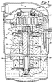
- a compressor 10 which comprises a generally cylindrical hermetic shell 12 having welded at the upper end thereof a cap 14.
- Cap 14 is provided with a refrigerant discharge fitting 18 which may have the usual discharge valve therein (not shown).
- Lower bearing housing 26 locates and supports within shell 12 two piece main bearing housing 24 and a motor 28 which includes a motor stator 30.
- a drive shaft or crankshaft 32 having an eccentric crank pin 34 at the upper end thereof is rotatably journaled in a bearing 36 in main bearing housing 24 and a second bearing 38 in lower bearing housing 26.
- Crankshaft 32 has at the lower end a relatively large diameter concentric bore 40 which communicates with a radially outwardly inclined smaller diameter bore 42 extending upwardly therefrom to the top of crankshaft 32. Disposed within bore 40 is a stirrer 44. The lower portion of the interior shell 12 defines an oil sump 46 which is filled with lubricating oil. Bore 40 acts as a pump to pump lubricating fluid up the crankshaft 32 and into bore 42 and ultimately to all of the various portions of the compressor which require lubrication.
- Crankshaft 32 is rotatively driven by electric motor 28 including motor stator 30, windings 48 passing therethrough and a motor rotor 50 press fitted on crankshaft 32 and having upper and lower counterweights 52 and 54, respectively.
- the upper surface of two piece main bearing housing 24 is provided with a flat thrust bearing surface 56 on which is disposed an orbiting scroll 58 having the usual spiral vane or wrap 60 on the upper surface thereof.
- a cylindrical hub Projecting downwardly from the lower surface of orbiting scroll 58 is a cylindrical hub having a journal bearing 62 therein and in which is rotatively disposed a drive bushing 64 having an inner bore 66 in which crank pin 34 is drivingly disposed.
- Crank pin 34 has a flat on one surface which drivingly engages a flat surface (not shown) formed in a portion of bore 66 to provide a radially compliant driving arrangement, such as shown in assignee's U.S. Letters Patent 4,877,382.
- Oldham coupling 68 is also provided positioned between orbiting scroll 58 and bearing housing 24. Oldham coupling 68 is keyed to orbiting scroll 58 and a non-orbiting scroll 70 to prevent rotational movement of orbiting scroll member 58. Oldham coupling 68 is preferably of the type disclosed in assignee's copending application EP-A-0479412.
- Non-orbiting scroll member 70 is also provided having a wrap 72 positioned in meshing engagement with wrap 60 of orbiting scroll 58.
- Non-orbiting scroll 70 has a centrally disposed discharge passage 74 which communicates with an upwardly open recess 76 which in turn is in fluid communication via an opening 78 in partition 22 with a discharge muffler chamber 80 defined by cap 14 and partition 22.
- the entrance to opening 78 has an annular seat portion 82 therearound.
- Non-orbiting scroll member 70 has in the upper surface thereof an annular recess 84 having parallel coaxial sidewalls in which is sealingly disposed for relative axial movement an annular floating seal 86 which serves to isolate the bottom of recess 84 from the presence of gas under suction pressure at 90 and discharge pressure at 88 so that it can be placed in fluid communication with a source of intermediate fluid pressure by means of a passageway 92.
- Non-orbiting scroll member 70 is thus axially biased against orbiting scroll member 58 to enhance wrap tip sealing by the forces created by discharge pressure acting on the central portion of scroll member 70 and those created by intermediate fluid pressure acting on the bottom of recess 84.
- Discharge gas in recess 76 and opening 78 is also sealed from gas at suction pressure in the shell by means of seal 86 acting against seat portion 82.
- This axial pressure biasing and the functioning of floating seal 86 are disclosed in greater detail in applicant's assignee's U.S. Letters Patent No. 5,156,539.
- Non-orbiting scroll member 70 is designed to be mounted to bearing housing 24 in a suitable manner which will provide limited axial (and no rotational) movement of non-orbiting scroll member 70.
- Non-orbiting scroll member 70 may be mounted in the manner disclosed in the aforementioned U.S. Patent No. 4,877,382 or U.S. Patent No. 5,102,316.
- the compressor is preferably of the "low side" type in which suction gas entering via fitting 20 is allowed, in part, to escape into the shell and assist in cooling the motor. So long as there is an adequate flow of returning suction gas the motor will remain within desired temperature limits. When this flow ceases, however, the loss of cooling will cause a motor protector 94 to trip and shut the machine down.
- both of the primary embodiments of the present invention utilize a very simple valve which functions at compressor shut down to allow gas flow from an area of intermediate pressure to an area of suction pressure.
- the valve of the present invention operates to allow gas at intermediate pressure to flow to an area of suction pressure which then allows discharge pressure to dump to suction pressure.
- the size, complexity and cost of the valve can be significantly reduced.
- the valve is operated by a solenoid, and in the second set of embodiments, the valve is run by a mechanical device. It is believed that all primary embodiments of the present invention are fully applicable to any type of scroll compressor.
- the first embodiment of the present invention is shown in Figures 1 through 3.
- the first embodiment makes use of the dual pressure balancing scheme described above which is used to axially balance non-orbiting scroll member 70 with floating seal 86 being used to separate the discharge gas pressure from the suction gas pressure.
- a solenoid valve 98 comprises a solenoid 100 and a valve 102. Solenoid valve 98 can be wired in parallel or in series with motor 28 such that solenoid 100 is activated and deactivated with motor 28 or solenoid valve 98 may be wired independently from motor 28. When solenoid valve 98 is wired independently from motor 28, valve 98 may be operated in a pulsed manner or a pulsed width modulated manner to modulate the capacity of compressor 10. Solenoid 100 is operable to open and close valve 102 which is in communication with a passageway 104 located within non-orbiting scroll 70. Passageway 104 extends from the bottom of recess 84 which is at intermediate pressure during operation of the compressor to the area of the compressor which contains suction gas at suction gas pressure.
- Solenoid 100 and valve 102 are best shown in Figure 2.
- Solenoid 100 includes a cylindrical wire coil 106 surrounding a plunger 108 in the usual manner.
- Solenoid 100 is secured to valve 102 by any method known well in the art.
- Valve 102 includes a valve body 110 having a passageway 112 which is in communication with passageway 104 in non-orbiting scroll 70.
- Valve body 110 is attached to non-orbiting scroll 70 by methods known well in the art.
- a ball 114 is disposed within passageway 112 and moveable between an open position and a closed position due to the movement of plunger 108. In its open position, fluid is allowed to flow from passageway 104 through passageway 112. In its closed position fluid is prohibited from flowing through passageways 104 and 112 due to ball 114 being forced against a valve seat 116 located within passageway 112 by plunger 108.
- solenoid 100 is energized and valve 102 is closed to block any fluid flow through passageway 104.
- compressor 10 makes a normal start-up.
- compression within the scrolls builds rapidly at start-up. This build up of pressure can be so rapid in fact that the compressor may stall because of insufficient motor torque. Generally, this is only a problem when using single phase motors. When this build up of pressure occurs, the motor stalls and the motor protector repeatedly trips and the compressor has a difficult time starting again.
- An option in the present invention is to build in a time delay to the activation of solenoid 100 to prevent the closing of passageway 104 at start-up, thus keeping intermediate pressure from building up. This lack of intermediate pressure will allow the scrolls to separate axially and prevent compression build-up until sufficient motor torque has been generated.
- solenoid 100 is de-energized at the same instant that power to motor 28 is cut off.
- the de-energization of solenoid 100 causes valve 102 to open and allows fluid flow through passageways 104 and 112 from the bottom of recess 84 to the suction area of compressor 10.
- floating seal 86 has a net downward force due to the discharge gas pressure and floating seal 86 moves downward in recess 84 and creates a discharge gas to suction gas leak across the top of floating seal 86 at annular seat portion 82.
- Solenoid valve 98 may be an AC (alternating current) or a DC (direct current) solenoid independent of the type of motor 28. If a DC solenoid is to be used with an AC motor, a rectifier needs to be wired between the AC power source and the DC solenoid.
- Figure 4 shows another embodiment of the present invention.
- elements which are the same as those in Figures 1 through 3 have been given the same reference numerals.
- the embodiment in Figures 1 through 3 purges intermediate pressure within recess 84 which holds non-orbiting scroll 70 down allowing floating seal 86 to drop.
- the embodiment shown in Figure 4 is incorporated into a compressor which uses intermediate pressure to bias orbiting scroll 58 upward.
- the embodiment shown in Figure 4 purges the intermediate pressure holding orbiting scroll 58 up which then creates sufficient tip clearance between the tips of scroll wraps 60 and 72 and their respective mating scroll to allow high pressure discharge gas to leak back through scrolls 58 and 70 before excessive reversals occur.
- FIG. 4 shows the upper section of a compressor 130.
- Compressor 130 is similar to compressor 10 with the exception that partition 22 of compressor 10 has been eliminated along with floating seal 86.
- non-orbiting, or in this case, stationary, scroll 70 extends completely across shell 12 and cap 14. Both shell 12 and cap 14 are secured to non-orbiting scroll 70 by welding or other means known well in the art.
- Main bearing housing 24 is provided with an annular chamber 132 extending into flat thrust bearing surface 56.
- a first annular seal 134 is positioned radially outward from chamber 132 and a second annular seal 136 is positioned radially inward from chamber 132. Seals 134 and 136 operate to prohibit fluid flow from chamber 132 to the suction side of compressor 130.
- a passageway 138 extends through orbiting scroll 58 and fluidically connects chamber 132 to an area of intermediate pressure within compressor 130. During operation of compressor 130, fluid at an intermediate pressure is supplied to chamber 132 through passageway 138. Orbiting scroll 58 is thus forced axially upward due to the fluid pressure within chamber 132. The fluid pressure within chamber 132 is maintained by seals 134 and 136.
- Compressor 130 further includes a passageway 140 extending through main bearing housing 24 and connecting chamber 132 to solenoid valve 98.
- the embodiment shown in Figure 4 includes a fluid tube 142 extending from passageway 140 to solenoid valve 98 which will allow the placement of solenoid valve 98 anywhere within the suction area of compressor 130 as space will permit. It will be appreciated that the use of tube 142 or its equivalent may be used with any of the embodiments of the present invention to facilitate packaging and design requirements. It is also possible to have tube 142 extend through shell 12 and have solenoid 100 and valve 102 located externally to shell 12 if desired.
- solenoid 100 is energized and valve 102 is closed to block any fluid flow from passageway 140 through passageway 112. In this way compressor 130 makes a normal start-up.
- the time delay feature at compressor start-up described above may also be built into solenoid valve 98 for this embodiment.
- solenoid 100 is de-energized causing valve 102 to open and allow fluid flow through passageways 140 and 112 from chamber 132 to the suction area of compressor 130. As the intermediate pressure and suction pressure are equalized, orbiting scroll 58 moves downward and creates a discharge gas to suction gas leak across the tips of scroll wraps 60 and 72.
- the amount of reverse rotation can be controlled by controlling the size of passageway 140 and/or passageway 112.
- the de-energization of valve 102 and the shut-down of motor 28 may also be tied in with a time delay to insure that sufficient leakage between chamber 132 and the suction area of the compressor has occurred before the motor is shut down. It is to be appreciated that this time delay feature at the shut down of the compressor can be applied to any of the embodiments of the present invention which incorporate solenoid valve 98.
- Figures 5 and 6 show another embodiment of the present invention.
- the embodiment shown in Figures 1 through 3 and the embodiment shown in Figure 4 utilize the purging of intermediate pressure from an existing chamber in the compressor which is being utilized to bias one of the scroll members towards the other.
- the effect of purging this intermediate pressure from a biasing chamber is to create a leak between existing compressor components which then allows the discharge gas pressure and suction gas pressure to equalize.
- FIG. 5 shows a compressor 150 having a pressure ratio sensitive valve 152 incorporated into orbiting scroll 58.
- the design of compressor 150 in Figure 5 is similar to the design of compressor 130 shown in Figure 4 in that non-orbiting scroll 70 is a fixed scroll attached to shell 12 and cap 14.
- Main bearing housing 24 is provided with annular chamber 132 extending into flat thrust bearing surface 56. Seals 134 and 136 operate to prohibit fluid flow from chamber 132 to the suction side of compressor 150.
- Passageway 138 extends through orbiting scroll 58 and connects chamber 132 to an area of intermediate pressure within compressor 150.
- the embodiment shown in Figure 5 includes a passageway 140 extending through main bearing housing 24 and connecting chamber 132 to solenoid valve 98.
- the embodiment shown in Figure 5 includes fluid tube 142 extending from passageway 140 which will allow the placement of solenoid valve 98 anywhere within the suction area of compressor 150 as space will permit.
- compressor 150 shown in Figure 5 is the same as compressor 130 shown in Figure 4 and the operation of compressor 150 is the same as the operation of compressor 130 as described above.
- Compressor 150 further includes pressure ratio sensitive valve 152 disposed within a pocket 154 located within orbiting scroll 58.
- a discharge pressure passageway 156 extends between discharge passageway 74 and pocket 154.
- a suction pressure passageway 158 extends between pocket 154 and the suction area of compressor 150.
- a valve body 160 is disposed within pocket 154 and is axially movable within pocket 154 to allow or prohibit fluid flow between passageway 156 and passageway 158.
- Valve body 160 and pocket 154 are designed such that valve body 160 is capable of axial movement within pocket 154 but fluid flow between valve body 160 and pocket 154 is prohibited.
- the upper surface of valve body 160 has an annular ring 162 which separates the area above valve body 160 into an annular chamber 164 and a cylindrical chamber 166.
- valve body 160 is determined by the various pressures operating against respective surface areas of valve body 160. Intermediate pressure within chamber 132 exerts an upward force on valve body 160 equal to the amount of intermediate pressure times the surface area of valve body 160 exposed to chamber 132.
- Discharge pressure is being supplied to annular chamber 164 and thus exerts a downward force on valve body 160 equal to the amount of discharge pressure times the surface area of valve body 160 exposed to chamber 164.
- suction pressure is being supplied to cylindrical chamber 166 and thus exerts a downward force on valve body 160 equal to the amount of suction pressure times the surface area of valve body 160 exposed to chamber 166.
- the opening and closing of pressure ratio sensitive valve 152 can be controlled by selecting the size of valve body 160 and the size and diameter of annular ring 162 to control the various surface areas.
- solenoid 100 is de-energized causing valve 102 to open and allow fluid flow through passageway 140 and 112 from chamber 132 to the suction area of compressor 150.
- both orbiting scroll 58 and valve body 160 are moved downward.
- the movement of scroll 58 causes a discharge gas to suction gas leak across the tips of scroll wraps 60 and 72 as explained above for the embodiment shown in Figure 4.
- the movement of valve body 160 within pocket 154 allows discharge gas to flow from passageway 156 through passageway 158 thus creating a direct fluid flow between the discharge gas and the suction gas.
- the various controls including the size of passageway 140 and/or passageway 112 and the time delay at compressor shut down described above for the embodiment shown in Figure 4 are also applicable to this embodiment.
- the amount of reverse rotation can be further controlled by the size of passageways 156 and 158 as well as the ratio of surface areas as described above for valve body 160.
- Figure 6 shows another embodiment of the present invention.
- Figure 6 shows a compressor 180 having a pressure ratio sensitive valve 182 disposed within a pocket located within non-orbiting or fixed scroll 70. Similar to the embodiment shown in Figures 1 through 3, compressor 180 includes fixed scroll 70, orbiting scroll 58, shell 12, cap 14 and partition 22. Compressor 180 has fixed scroll 70 bolted directly to partition 22 by a plurality of bolts 184. Because non-orbiting or fixed scroll 70 does not move axially as in Figures 1 through 3, the need for floating seal 86 has been eliminated. Compressor 180 may or may not utilize biasing chamber 132 located within main bearing housing 24 in conjunction with seals 134 and 136 to bias orbiting scroll 58 towards fixed scroll 70 in a manner similar to that described for the embodiment shown in Figure 4 but not shown in Figure 6.
- Compressor 180 includes pressure ratio sensitive valve 182 disposed within a pocket 186 located within fixed scroll 70.
- An intermediate pressure passageway 188 extends between an intermediate pressure zone within compressor 180 and pocket 186.
- a vent passageway 190 extends between pocket 186 and the inlet to solenoid valve 98.
- Solenoid valve 98 may be attached directly to fixed scroll 70 as shown in Figure 1 or it may be located remotely from fixed scroll 70 by using tube 142 as shown in Figures 4 and 6.
- a valve body 192 is disposed within pocket 186 and is axially movable within pocket 186 to allow or prohibit fluid flow through an orifice 194 extending through partition 22.
- Valve body 192 and pocket 186 are designed such that valve body 192 is capable of axial movement within pocket 186 but fluid flow between valve body 192 and pocket 186 is prohibited by sliding seal 196.
- the upper surface of valve body 192 has a cylindrical extension 198 which is adapted with a valve seat 200 for sealing orifice 194.
- valve body 192 is determined by the various pressures operating against respective surface areas of valve body 192. Intermediate pressure within pocket 186 exerts an upward force on valve body 192 equal to the amount of intermediate pressure times the surface area of the valve body 192.
- Discharge pressure is being supplied to orifice 194 and thus exerts a downward force on valve body 192 equal to the amount of discharge pressure times the area of orifice 194.
- suction pressure is present at the upper end of pocket 186 and thus exerts a downward force on valve body 192 equal to the amount of suction pressure times the surface area of valve body 192 minus the surface area of orifice 194.
- the opening and closing of pressure ratio sensitive valve 182 can be controlled by selecting the size of valve body 192 and the size of orifice 194.
- solenoid 100 is de-energized causing valve 102 to open and allow fluid flow through passageways 190 and 112 from pocket 186 to the suction area of compressor 180.
- valve body 192 moves downward due to discharge pressure at orifice 194.
- the movement of valve body 192 within pocket 186 creates a direct fluid flow between the discharge gas and the suction gas through orifice 194.
- the various controls including the size of passageway 190 and/or passageway 112 and the time delay at compressor shut down described for the embodiment in Figure 4 are also applicable to this embodiment.
- the amount of reverse rotation can be further controlled by the size of orifice 194 in relationship to the size of valve body 192 as described above.
- Figures 7 and 8 show another embodiment of the present invention.
- Figures 7 and 8 eliminate the need for solenoid valve 98.
- the compressor shown in Figures 7 and 8 utilize motor 28 and crankshaft 32 to perform the switching function of solenoid valve 98.
- a solenoid is basically a wire coil which generates a magnetic field, which in turn pushes or pulls a plunger within the coil. This is very similar to the compressor motor.
- Motor stator 30 creates a rotating magnetic field which tends to axially center motor rotor 50 within motor stator 30.
- the embodiment shown in Figures 7 and 8 use this centering force in conjunction with an opposing spring force to create the same result as a solenoid.
- FIG. 7 shows compressor 220 which is similar to compressor 10 shown in Figure 1 except that solenoid valve 98 has been replaced by tube 142 and a valve 222 which uses motor 28 and crankshaft 32 for opening and closing.
- Passageway 104 extends through non-orbiting scroll 70 and is sealingly secured to tube 142.
- Tube 142 is routed through compressor 220 and its opposite end is sealingly secured to a passageway 224 extending through main bearing housing 24.
- Passageway 224 extends from one side of main bearing housing 24 to an upper surface 226 where it is open to the suction area of compressor 220.
- Crankshaft 32 extends through main bearing housing 24 and has an annular sealing flange 228 attached to crankshaft 32 at a position adjacent to upper surface 226.
- flange 228 is shown integral with crankshaft 32 and upper counterweight 52 is attached to flange 228. It is within the scope of the present invention to have flange 228 and counterweight 52 formed as one piece and attached to crankshaft 32 if desired.
- Crankshaft 32 is normally biased upward by a biasing spring 230 positioned between lower bearing housing 26 and crankshaft 32 such that sealing flange 228 is biased away from upper surface 226 and passageway 224 is open to the suction area of compressor 220.
- crankshaft 32 is forced downward against the load of biasing spring 230 due to the centering force created by the magnetic field of motor 28 which tends to axially center motor rotor 50 and thus crankshaft 32 within motor stator 30.
- This downward movement of crankshaft 32 brings into contact sealing flange 228 and upper surface 226 which prohibits fluid flow through passageway 224. In this manner, compressor 10 makes a normal start-up.
- Figure 8 shows another embodiment of the present invention which is similar to the embodiment in Figure 4 but utilizes motor 28 and crankshaft 32 as the valve similar to that described above for Figure 7.
- Figure 8 shows a compressor 240 which includes an intermediate gas pressure biasing chamber 132 similar to that shown in Figure 4.
- Compressor 240 also includes a passageway 242 which extends from a horizontal surface 244 on bearing housing 24 to meet a passageway 246 extending from biasing chamber 132.
- compressor 240 is identical to the operation of compressor 220 described above except that the intermediate pressure is released from below the orbiting scroll rather than from below floating seat 86 and the discharge gas to suction gas leak is created identical to that described in Figure 4.
- a pressure ratio sensitive valve as described in the embodiments shown in Figures 5 and 6 may also be incorporated into compressor 240 if desired.
- FIGS 9 and 10 show another embodiment of the present invention.
- the embodiment shown in Figures 9 and 10 makes use of centrifugal force to activate a valve above a predetermined rotational speed.
- This valve is biased to an open position at low speed allowing the purging of the intermediate pressure gas.
- this centrifugal valve can be utilized with any of the embodiments described above whereby the centrifugal valve replaces the solenoid valve.
- FIGS 9 and 10 show a compressor 250 which incorporates a centrifugal valve 252 to replace solenoid valve 98.
- Centrifugal valve 252 as best shown in Figure 10 includes a valve body 254 secured to crankshaft 32 for rotation therewith but capable of axial movement along crankshaft 32.
- a valve spring 256 biases valve body 254 axially along crankshaft 32 and sealingly engages valve body 254 with main bearing housing 24.
- a first passageway 258 extends radially through valve body 254.
- a valve 260 is slidingly received within passageway 258 and is biased radially inward by a coil spring 262. The radial outward end of passageway 258 is closed by a ball 264 which also provides for a reaction point for coil spring 262.
- valve body 254 which is opposite to valve spring 256 is provided with an annular groove 266 which is in communication with passageway 224 in main bearing housing 24.
- An axial passageway 268 extends from annular groove 266 through radial passageway 258 and into the suction area of compressor 250.
- passageway 224 is open to the suction area of compressor 250 through groove 266 and axial passageway 268.
- valve 260 will block axial passageway 268 and prohibit fluid flow from passageway 224 to the suction area of compressor 250.
- valve 260 is biased radially inward by coil spring 262. As the rotational speed of crankshaft 32 and centrifugal valve 252 increases, valve 260 is forced radially outward to block axial passageway 268. In this manner, compressor 250 makes a normal start-up.
- valve 260 At compressor shut-down, valve 260 will remain in a position to block axial passageway 268 until such a time that the load exerted by coil spring 262 exceeds the centrifugal force exerted on valve 260 as the rotational speed of centrifugal valve 252 decreases. Eventually valve 260 will move sufficiently inward to open axial passageway 268 and the intermediate pressure within passageway 224 will be purged to the suction area of compressor 250. The purging of the intermediate pressure to suction pressure has the identical effect as described above for the previous embodiments. The rate control for this embodiment would involve the size of axial passageway 268, the weight of valve 260 and the rate for coil spring 262.
- Figures 11 and 12 show schematically another embodiment of the present invention.
- the embodiment shown in Figures 11 and 12 uses angular acceleration at start-up to block a vent hole, and deceleration at shut-down to unblock the vent hole and allow the purging of intermediate gas pressure to suction gas pressure.
- Figures 11 and 12 schematically represent the reverse rotation protection of this embodiment of the present invention and include crankshaft 32, main bearing housing 24, passageway 224, a valve 280 and a collar 282.
- Valve 280 is located within passageway 224 at the point where passageway 224 extends through upper surface 244.
- Valve 280 includes a ball 284, an activation device 286 and a valve seat 288.
- Collar 280 is slidingly received on crankshaft 32 at a position adjacent to upper surface 244 on main bearing housing 24.
- Collar 282 includes a pin 290 which extends through collar 282 and is disposed in a spiral groove 292 located in crankshaft 32.
- a coil spring 294 biases collar 282 downward towards upper surface 244 on main bearing housing 24. In the lower position shown in Figure 11, collar 282 contacts activation device 286 which in turn forces ball 284 against valve seat 288 to prohibit movement of fluid through passageway 224.
- the intermediate pressure acting against ball 284 forces ball 284 upward opening passageway 224 to the suction area of the compressor.
- crankshaft 32 causes relative movement between crankshaft 32 and collar 282 due to the inertial effects on collar 282.
- the direction of spiral groove 292 is such that this positive angular acceleration of crankshaft 32 causes pin 290 to move downward in groove 292 forcing collar 282 against upper surface 226 and closing valve 280 by forcing ball 284 against valve seat 288. In this manner, the compressor makes a normal start-up.
- Figures 13 and 14 show another embodiment of the present invention.
- the embodiment shown in Figures 13 and 14 uses a viscous drag caused by a rotating component of the compressor.
- the rotating component shown is crankshaft 32, although any rotating component within the compressor could be used.
- Viscous drag caused by a rotating component can generate sufficient force to rotate a spring loaded device into a position to block a vent hole or to actuate a valve.
- Figures 13 and 14 schematically represent the reverse rotation protection of this embodiment of the present invention and include crankshaft 32, a collar 300 and a valve 302.
- Valve 302 includes a valve body 304, a valve spring 306, a first passageway 308, a valve 310 and a second passageway 312.
- Collar 300 is slidingly received on crankshaft 32 as shown in Figures 13 and 14.
- the relationship between the outside diameter of crankshaft 32 and the inside diameter of collar 300 is such that a viscous fluid film 314 exists between crankshaft 32 and collar 300.
- the rotating of crankshaft 32 attempts to shear viscous fluid film 314 between the two components. This shearing of the viscous fluid will cause a torque to be applied to collar 300 as viscous fluid film 314 attempts to rotate collar 300 with crankshaft 32.
- Collar 300 is provided with a radially extending paddle 316 which is used to activate valve 302 as will be described later herein.
- Valve body 304 may be secured to main bearing housing 24 similar to the attachment of valve 104 to non-orbiting scroll 70 shown in Figures 1 through 3 or valve body 304 may be separate from main bearing housing and provided with intermediate pressure by tube 142.
- First passageway 308 extends longitudinally through valve body 304.
- Valve 310 is slidingly received within passageway 308 and is biased towards paddle 316 of collar 300 as shown in Figure 13 by valve spring 306.
- the end of passageway 308 opposite to valve 310 is closed by a ball 318 which also provide for a reaction point for valve spring 306.
- Second passageway 312 extends through valve body 304 and through first passageway 308 generally perpendicular to first passageway 308. One end of second passageway 312 is connected to the source of intermediate pressure either directly through passageway 224 or through tube 142. The opposite end of second passageway 312 is open to the suction area of the compressor. When valve spring 306 biases valve 310 towards paddle 316, second passageway 312 is open and the source of intermediate pressure is open to the suction area of the compressor.
- paddle 316 exerts a load on valve 310 which overcomes the force of valve spring 306 and moves valve 310 to a position which blocks second passageway 312 and prohibits the source of intermediate pressure from purging to the suction area of the compressor.
- valve 310 is biased towards paddle 316 by valve spring 306.
- valve spring 306 As the rotational speed difference between crankshaft 32 and collar 300 increases, the torque exerted on collar 300 increases due to the shear of viscous fluid film 314 between crankshaft 32 and collar 300. The rotation of collar 300 with crankshaft 32 is prohibited by paddle 316 contacting valve 310.
- the load on valve 310 increases and valve 310 is forced longitudinally within first passageway 308 against valve spring 306 to block second passageway 312. In this manner, compressor 250 makes a normal start-up.
- valve 310 At compressor shut-down, valve 310 will remain in a position to block second passageway 312 until such a time that the load exerted by valve spring 306 exceeds the load exerted by paddle 316 on valve 310 as the rotational speed difference between crankshaft 32 and collar 300 decreases. Eventually valve 310 will move sufficiently inward to open second passageway 312 and the source of intermediate pressure will be purged to the suction area of the compressor.
- the purging of the intermediate pressure in this embodiment has the identical effect as described for the previous embodiments.
- the rate control for this embodiment would include the size of second passageway 312, the rate for valve spring 306 and the width of fluid film 314.
- Figures 15 through 17 illustrate schematically a fail-safe device which may be incorporated into a solenoid valve 350 which would be a replacement for solenoid valve 98 of the previous embodiments.
- Solenoid valve 350 operates similar to the operation of solenoid valve 98. Solenoid valve 98, when energized, pushes ball 114 onto valve seat 116 to prohibit fluid flow through passageway 112. Solenoid valve 350, when energized, moves away from a ball to allow the ball to seat on a valve seat. When solenoid valve 350 is de-energized it pushes the ball off of the valve seat to allow fluid flow through the valve.
- Figures 15 through 17 schematically illustrate solenoid valve 350 which includes a solenoid 352, a dashpot 354 and a valve 356.
- Solenoid 352 comprises a cylindrical wire coil 358, surrounding a plunger 360 in the usual manner.
- a return spring 362 forces plunger 360 towards the left as shown in Figure 15.
- Dashpot 354 comprises an outer housing 364 which is fixedly secured to plunger 360, an inner housing 366, and a dashpot spring 368.
- Inner housing 366 is slidingly received within a pocket 370 located within outer housing 364.
- Dashpot spring 368 is disposed within pocket 370 and urges inner housing 366 to the left as shown in Figure 15.
- Inner housing 366 includes an actuation pin 372 which extends from housing 366 towards valve 356 for opening and closing valve 356 as will be described later herein.
- Valve 356 comprises a valve body 374, a ball 376 and a valve spring 378.
- Valve body 374 includes a bore 380 extending longitudinally within valve body 374.
- Ball 376 is disposed within bore 380 and is urged to the right as shown in Figure 15 against a valve seat 382 by valve spring 378.
- the source of intermediate pressure is supplied to bore 380 either directly or by tube 142.
- solenoid valve 350 begins with solenoid 352 being de-energized, dashpot 354 being collapsed and valve 356 being closed due to valve spring 378 urging ball 376 against valve seat 382. This position is illustrated schematically in Figure 15. Activation pin 372 is biased against ball 376 by dashpot spring 368 but it is not able to unseat ball 376 due to the force exerted on ball 376 by valve spring 378. The rate of valve spring 378 is chosen to be higher than the rate of dashpot spring 368.
- solenoid 352 is energized and plunger 360 is urged to the right as shown in Figure 16. This urges outer housing 364 to the right also and dashpot 354 extends axially due to the load exerted by dashpot spring 368. This extension of dashpot 354 maintains the contact between activation pin 372 and ball 376. In this manner, the compressor will have a normal start-up.
- solenoid 352 is de-energized and plunger 360 is forced to the left as shown in Figure 17 due to return spring 362.
- the movement to the left of plunger 360 moves dashpot 354 to the left causing activation pin 372 to unseat ball 376 from valve seat 382.
- Valve spring 378 is unable to overcome the load exerted by activation pin 372 due to the force being exerted by return spring 362 and the resistance to collapsing of dashpot 354.
- the rate of return spring 362 is chosen to be higher than the rate of valve spring 378. Ball 376 will remain unseated from valve seat 382 for a period of time defined by the design of dashpot 354.
- Valve spring 378 will eventually work to collapse dashpot 354 and seat ball 376 against valve seat 382. This returns solenoid valve 350 to the position shown in Figure 15. During the time that ball 376 is unseated from valve seat 382, the gas at intermediate pressure will be purged to the suction area of the compressor. The purging of the intermediate pressure in this embodiment has the identical effect as described for the previous embodiments.
- the rate control for this embodiment would include the size of valve seat 382, the rates for springs 362, 368 and 378 as well as the rate for dashpot 354.
- solenoid valve 350 works by allowing valve 356 to remain seated if plunger 360 fails to retract at start-up, fails to return at shut-down or is stuck in any other position for whatever reason. If dashpot 354 itself fails, in either the collapsed or extended position, the compressor will function in a normal manner albeit with a loud shut-down.
- Figures 18 and 19 show another embodiment of the present invention.
- the purging of the intermediate pressurized gas to the suction area of the compressor was directly related to the start-up and shut-down of the compressor.
- the embodiment shown in Figures 18 and 19 uses a thermal switch to activate the purging of the source of intermediate pressurized gas to the suction area of the compressor. Once the thermal protector is switched, the dumping of the source of intermediate pressurized gas will allow discharge gas to leak to the suction area of the compressor as detailed above in the previous embodiments. The discharge gas to suction leak will lower the operating pressure ratio of the compressor and the discharge side temperature. Eventually the motor protector for the compressor will take the compressor off line due to high temperature discharge gas being leaked to the suction area of the compressor where the motor and motor protector are located.
- FIGS 18 and 19 illustrate schematically the thermal responsive valve of the present invention which is generally designated by reference numeral 400.
- Valve 400 comprises a valve body 402, a first chamber 404, a second chamber 406, a discharge pressure passageway 408 and a suction pressure passageway 410.
- Valve body 402 can be a separate component or valve body 402 may be an integral part of non-orbiting scroll 70, main bearing housing 24 or any other component within the compressor.
- First chamber 404 extends into valve body 402 and is placed in communication with the discharge gas of the compressor.
- Discharge pressure passageway 408 extends from the lower end of chamber 404 and fluidically connects chamber 404 with the lower end of chamber 406.
- a therm-o-disc (TOD) 410 is located on the step formed by chamber 404 and passageway 408. TOD 410 remains seated prohibiting discharge gas flow from chamber 404 to passageway 408. When a predetermined critical temperature is encountered, TOD 410 opens and allows full flow of discharge gas from chamber 404 to passageway 408.
- Second chamber 406 is a stepped chamber also extending into valve body 402.
- the upper or larger portion of chamber 406 is placed in communication with the source of intermediate pressurized gas.
- the lower or smaller portion of chamber 406 is placed in communication with chamber 404 through passageway 408.
- Suction pressure passageway 410 extends from a suction gas area within the compressor to the lower portion of chamber 406. The point at which suction pressure passageway 410 enters chamber 406 is between high pressure passageway 408 and the upper or larger portion of chamber 406.
- a flat check valve 412 having a piston 414 extending from it is disposed within chamber 406.
- Flat check valve 412 and piston 414 move together within chamber 406 from a closed position as shown in Figure 18 to an open position as shown in Figure 19.
- a retainer 416 limits the movement of flat check valve 412 and piston 414 within chamber 406.
- flat check valve 412 In its closed position, as shown in Figure 18, flat check valve 412 seats against the step formed in chamber 406 to prohibit fluid flow from the source of intermediate pressurized gas being supplied to the upper portion of chamber 406 to suction pressure passageway 410.
- Flat check valve 412 is forced downward due to the intermediate pressurized gas reacting on the exposed area of the step of check valve 412 and suction gas pressure reacting on the exposed area of piston 414.
- Flat check valve 412 will be forced upward due to the discharge gas pressure acting against piston 414 when TOD 410 is in the open condition. In its open position, as shown in Figure 19, flat check valve 412 is lifted from the stepped portion of chamber 406 and gas at intermediate pressure is allowed to leak to the suction side of the compressor. Retainer 416 limits the movement of flat check valve 412 such that discharge gas within passageway 408 is not allowed to flow into the suction area of the compressor.
- Thermal responsive valve 400 is normally positioned as shown in Figure 18. Discharge gas is being supplied to chamber 404 and intermediate pressurized gas is being supplied to chamber 406. The compressor operates normally as long as TOD 410 remains closed. When TOD 410 experiences an over temperature condition of the discharge gas within chamber 404, TOD 410 opens and allows discharge gas to enter passageway 408. The pressure of the discharge gas reacts against the exposed surface area of piston 414 raising flat check valve 412 which allows the source of intermediate pressurized gas in communication with chamber 406 to purge through passageway 410 and into the suction area of the compressor. This purging of the intermediate gas within the compressor allows a discharge gas to suction gas leak with the effects as described above for the various embodiments.
- the motor will continue to run with the compressor having a lower operating pressure ratio and a lower discharge side temperature. The motor will continue to run until the motor protector takes the compressor of line due to the high temperature discharge gas being leaked into the suction area of the compressor where the motor and motor protector are located.
Description
Claims (20)
- A scroll machine comprising:a first scroll member (58) having a first spiral wrap (60) projecting outwardly from an end plate;a second scroll member (70) having a second spiral wrap (72) projecting outwardly from an end plate, said second spiral wrap being intermeshed with said first spiral wrap;a drive member (32) for causing said scroll members to orbit relative to one another whereby said spiral wraps will create pockets of progressively changing volume between a suction pressure zone and a discharge pressure zone, said scroll machine including a leakage path disposed between said discharge pressure zone and said suction pressure zone, said leakage path being closed due to the influence of a pressurized fluid; characterised by:a valve member (98) for releasing said pressurized fluid to said suction pressure zone of said scroll machine; and in that one of said scroll members (70) is mounted for limited axial movement with respect to the other scroll member (58), said one scroll being biased towards said other scroll member by said pressurized fluid to close said leakage path, whereby said leakage path between said discharge pressure zone and said suction zone is opened when said pressurized fluid is released.
- The scroll machine according to claim 1, wherein said leakage path is located between said first and second scroll members (58, 70).
- A scroll machine according to claim 1 or 2, wherein said valve member (98) includes a solenoid valve (98).
- The scroll machine according to claim 3, wherein a fail safe device is incorporated into said solenoid valve (350).
- The scroll machine according to claim 3 or 4, wherein said drive member includes an electric motor (28), said electric motor and said solenoid valve (98) being wired in parallel.
- A scroll machine according to claim 3, wherein said drive member includes an electric motor, said electric motor and said solenoid valve being wired in series.
- A scroll machine according to claim 3, wherein said drive member includes an electric motor, said solenoid valve being wired independently from said electric motor.
- A scroll machine according to claim 5, 6 or 7, wherein a time delay is incorporated between the start-up of said motor (28) and the activation of said solenoid valve (98).
- A scroll machine according to any one of claims 5, 6, 7 or 8, wherein a time delay is incorporated between the de-activation of said solenoid valve (98) and the shutdown of said motor (28).
- A scroll machine according to claim 7, wherein said solenoid valve is operable in a pulsed manner to modulate the capacity of said scroll machine.
- A scroll machine according to any one of claims 3 to 10, wherein said solenoid valve is a DC solenoid valve.
- A scroll machine according to any one of claims 3 to 10, wherein said solenoid valve is an AC solenoid valve.
- A scroll machine according to claim 1 or 2, wherein said valve member includes a mechanical valve (252).
- The scroll machine according to claim 13, wherein said mechanical valve (252) is arranged to be operated by centrifugal force.
- The scroll machine according to claim 13, wherein said mechanical valve (280) is arranged to be operated by angular acceleration of a component of said scroll machine.
- The scroll machine according to claim 13, wherein said mechanical valve (302) is arranged to be operated by viscous drag between said mechanical valve and a component of said scroll machine.
- The scroll machine according to any one of the preceding claims, wherein said valve member (400) includes a temperature sensing member (410) such that said valve member is opened when said temperature sensing member senses an over temperature condition within said scroll machine.
- The scroll machine according to claim 1, wherein said drive member (32) is operable to open and close said valve member.
- The scroll machine according to claim 1, wherein said valve member includes a pressure ratio sensitive valve (182).
- The scroll machine according to claim 1 further comprising:a partition (22) between said discharge zone and said suction zone, said leakage path (194) being located within said partition; anda valve body (192) for closing said leakage path, said valve body being operable to open and close said leakage path due to the influence of said pressurized fluid, said leakage path being closed when said pressurized fluid is being supplied to said valve body.
Applications Claiming Priority (2)
| Application Number | Priority Date | Filing Date | Title |
|---|---|---|---|
| US08/158,754 US5591014A (en) | 1993-11-29 | 1993-11-29 | Scroll machine with reverse rotation protection |
| US158754 | 1993-11-29 |
Publications (2)
| Publication Number | Publication Date |
|---|---|
| EP0655555A1 EP0655555A1 (en) | 1995-05-31 |
| EP0655555B1 true EP0655555B1 (en) | 1998-06-17 |
Family
ID=22569556
Family Applications (1)
| Application Number | Title | Priority Date | Filing Date |
|---|---|---|---|
| EP94307815A Expired - Lifetime EP0655555B1 (en) | 1993-11-29 | 1994-10-25 | Scroll machine with reverse rotation protection |
Country Status (6)
| Country | Link |
|---|---|
| US (1) | US5591014A (en) |
| EP (1) | EP0655555B1 (en) |
| JP (1) | JPH07189945A (en) |
| KR (1) | KR100294430B1 (en) |
| CN (1) | CN1071418C (en) |
| DE (1) | DE69411131T2 (en) |
Families Citing this family (56)
| Publication number | Priority date | Publication date | Assignee | Title |
|---|---|---|---|---|
| US5803716A (en) * | 1993-11-29 | 1998-09-08 | Copeland Corporation | Scroll machine with reverse rotation protection |
| US6047557A (en) * | 1995-06-07 | 2000-04-11 | Copeland Corporation | Adaptive control for a refrigeration system using pulse width modulated duty cycle scroll compressor |
| JP3750169B2 (en) * | 1995-12-27 | 2006-03-01 | ダイキン工業株式会社 | Hermetic compressor |
| JPH09310688A (en) * | 1996-05-21 | 1997-12-02 | Sanden Corp | Variable displacement type scroll compressor |
| JP3772393B2 (en) * | 1996-05-28 | 2006-05-10 | ダイキン工業株式会社 | Scroll compressor |
| US6086342A (en) * | 1997-08-21 | 2000-07-11 | Tecumseh Products Company | Intermediate pressure regulating valve for a scroll machine |
| US6077057A (en) * | 1997-08-29 | 2000-06-20 | Scroll Technologies | Scroll compressor with back pressure seal protection during reverse rotation |
| US6206652B1 (en) | 1998-08-25 | 2001-03-27 | Copeland Corporation | Compressor capacity modulation |
| US6120255A (en) * | 1998-01-16 | 2000-09-19 | Copeland Corporation | Scroll machine with capacity modulation |
| US6190138B1 (en) * | 1998-06-12 | 2001-02-20 | Scroll Technologies | Flow valve for correcting reverse rotation in scroll compressor |
| US6168404B1 (en) * | 1998-12-16 | 2001-01-02 | Tecumseh Products Company | Scroll compressor having axial compliance valve |
| CN1192169C (en) * | 1999-06-01 | 2005-03-09 | Lg电子株式会社 | Apparatus for preventing vacuum compression of scroll compressor |
| US6220839B1 (en) * | 1999-07-07 | 2001-04-24 | Copeland Corporation | Scroll compressor discharge muffler |
| US6267565B1 (en) | 1999-08-25 | 2001-07-31 | Copeland Corporation | Scroll temperature protection |
| US6293767B1 (en) | 2000-02-28 | 2001-09-25 | Copeland Corporation | Scroll machine with asymmetrical bleed hole |
| US6419457B1 (en) * | 2000-10-16 | 2002-07-16 | Copeland Corporation | Dual volume-ratio scroll machine |
| KR100417581B1 (en) * | 2001-01-31 | 2004-02-05 | 주식회사 엘지이아이 | Orbited scroll reverse rotation precluding apparatus for scroll compressor |
| US6551069B2 (en) | 2001-06-11 | 2003-04-22 | Bristol Compressors, Inc. | Compressor with a capacity modulation system utilizing a re-expansion chamber |
| US6821092B1 (en) | 2003-07-15 | 2004-11-23 | Copeland Corporation | Capacity modulated scroll compressor |
| JP2005171836A (en) * | 2003-12-10 | 2005-06-30 | Daikin Ind Ltd | Fluid machinery |
| KR100585798B1 (en) * | 2003-12-19 | 2006-06-07 | 엘지전자 주식회사 | Apparatus preventing over heating for scroll compressor |
| KR100575829B1 (en) | 2003-12-31 | 2006-05-03 | 엘지전자 주식회사 | Suction-muffler assembly structure for reciprocating compressor |
| US7314357B2 (en) | 2005-05-02 | 2008-01-01 | Tecumseh Products Company | Seal member for scroll compressors |
| CN1896539B (en) * | 2005-07-12 | 2010-05-05 | 乐金电子(天津)电器有限公司 | Oil feeder of reeling compressor |
| US20070036661A1 (en) * | 2005-08-12 | 2007-02-15 | Copeland Corporation | Capacity modulated scroll compressor |
| US7322806B2 (en) * | 2006-01-04 | 2008-01-29 | Scroll Technologies | Scroll compressor with externally installed thermostat |
| JP4864689B2 (en) * | 2006-04-17 | 2012-02-01 | 株式会社デンソー | Fluid machinery and Rankine cycle |
| US7547202B2 (en) * | 2006-12-08 | 2009-06-16 | Emerson Climate Technologies, Inc. | Scroll compressor with capacity modulation |
| US7717687B2 (en) * | 2007-03-23 | 2010-05-18 | Emerson Climate Technologies, Inc. | Scroll compressor with compliant retainer |
| US20090071183A1 (en) * | 2007-07-02 | 2009-03-19 | Christopher Stover | Capacity modulated compressor |
| US8157538B2 (en) | 2007-07-23 | 2012-04-17 | Emerson Climate Technologies, Inc. | Capacity modulation system for compressor and method |
| CN201972923U (en) | 2007-10-24 | 2011-09-14 | 艾默生环境优化技术有限公司 | Scroll machine |
| KR101376619B1 (en) | 2008-04-04 | 2014-03-20 | 엘지전자 주식회사 | Scroll Compressor |
| CA2749562C (en) | 2009-01-27 | 2014-06-10 | Emerson Climate Technologies, Inc. | Unloader system and method for a compressor |
| US7988433B2 (en) | 2009-04-07 | 2011-08-02 | Emerson Climate Technologies, Inc. | Compressor having capacity modulation assembly |
| CN102713156B (en) * | 2010-01-19 | 2014-08-27 | 三菱电机株式会社 | Volume type expander and refrigeration cycle device using the volume type expander |
| CN103790831B (en) * | 2012-10-30 | 2016-09-07 | 艾默生环境优化技术(苏州)有限公司 | Compressor with a compressor housing having a plurality of compressor blades |
| US9249802B2 (en) | 2012-11-15 | 2016-02-02 | Emerson Climate Technologies, Inc. | Compressor |
| US9581161B2 (en) * | 2012-11-21 | 2017-02-28 | Emerson Climate Technologies, Inc. | Compressor with service valve assembly |
| CN105026764B (en) | 2013-02-06 | 2018-06-12 | 艾默生环境优化技术有限公司 | Capacity modulated scroll formula compressor |
| JP6548880B2 (en) * | 2014-09-17 | 2019-07-24 | 三菱重工サーマルシステムズ株式会社 | Scroll compressor |
| CN106194737B (en) * | 2015-05-06 | 2018-06-19 | 丹佛斯(天津)有限公司 | For controlling the control module of compressor and compressor control method |
| WO2018063976A1 (en) * | 2016-09-27 | 2018-04-05 | Atlas Copco Comptec, Llc | Integrated oil system manifold |
| US10865792B2 (en) * | 2017-06-16 | 2020-12-15 | Trane International Inc. | Aerostatic thrust bearing and method of aerostatically supporting a thrust load in a scroll compressor |
| US11415135B2 (en) * | 2017-06-16 | 2022-08-16 | Trane International Inc. | Aerostatic thrust bearing and method of aerostatically supporting a thrust load in a scroll compressor |
| US10718333B2 (en) | 2017-06-16 | 2020-07-21 | Trane International Inc. | Aerostatic thrust bearing method and method of aerostatically supporting a thrust load in a scroll compressor |
| US11022119B2 (en) | 2017-10-03 | 2021-06-01 | Emerson Climate Technologies, Inc. | Variable volume ratio compressor |
| EP3489516B1 (en) * | 2017-11-24 | 2021-09-01 | Pfeiffer Vacuum Gmbh | Vacuum pump |
| US10962008B2 (en) | 2017-12-15 | 2021-03-30 | Emerson Climate Technologies, Inc. | Variable volume ratio compressor |
| CN112219076A (en) | 2018-04-09 | 2021-01-12 | 开利公司 | Preventing reverse rotation in a centrifugal compressor |
| US10995753B2 (en) | 2018-05-17 | 2021-05-04 | Emerson Climate Technologies, Inc. | Compressor having capacity modulation assembly |
| CN208651145U (en) * | 2018-06-22 | 2019-03-26 | 艾默生环境优化技术(苏州)有限公司 | Scroll compressor having a plurality of scroll members |
| US11204029B2 (en) * | 2018-11-14 | 2021-12-21 | Quincy Compressor Llc | Loadless start valve for a compressor |
| US11656003B2 (en) | 2019-03-11 | 2023-05-23 | Emerson Climate Technologies, Inc. | Climate-control system having valve assembly |
| US11655813B2 (en) | 2021-07-29 | 2023-05-23 | Emerson Climate Technologies, Inc. | Compressor modulation system with multi-way valve |
| US11846287B1 (en) | 2022-08-11 | 2023-12-19 | Copeland Lp | Scroll compressor with center hub |
Family Cites Families (28)
| Publication number | Priority date | Publication date | Assignee | Title |
|---|---|---|---|---|
| US912866A (en) * | 1906-05-28 | 1909-02-16 | Robert F Massa | System of refrigeration. |
| US1942433A (en) * | 1930-10-16 | 1934-01-09 | Etta M Lindsay | Automatic unloader for compressors |
| US2062052A (en) * | 1932-06-30 | 1936-11-24 | Gen Motors Corp | Motor-compressor unit for refrigerating apparatus |
| US2069767A (en) * | 1932-12-23 | 1937-02-09 | Gen Motors Corp | Compressing apparatus |
| US2373909A (en) * | 1941-09-25 | 1945-04-17 | Gen Motors Corp | Refrigerating apparatus |
| JPS5776287A (en) * | 1980-10-31 | 1982-05-13 | Hitachi Ltd | Scroll compressor |
| US4335582A (en) * | 1981-02-20 | 1982-06-22 | Dunham-Bush, Inc. | Unloading control system for helical screw compressor refrigeration system |
| JPS58220988A (en) * | 1982-06-17 | 1983-12-22 | Mitsubishi Electric Corp | Scroll compressor |
| JPS59105994A (en) * | 1982-12-10 | 1984-06-19 | Toyoda Autom Loom Works Ltd | Capacity control mechanism in scroll type compressor |
| JPH061073B2 (en) * | 1984-10-11 | 1994-01-05 | 株式会社日立製作所 | Scroll compressor |
| US4596520A (en) * | 1983-12-14 | 1986-06-24 | Hitachi, Ltd. | Hermetic scroll compressor with pressure differential control means for a back-pressure chamber |
| EP0326189B1 (en) * | 1985-08-10 | 1991-12-11 | Sanden Corporation | Scroll type compressor with variable displacement mechanism |
| US4877382A (en) * | 1986-08-22 | 1989-10-31 | Copeland Corporation | Scroll-type machine with axially compliant mounting |
| US5102316A (en) * | 1986-08-22 | 1992-04-07 | Copeland Corporation | Non-orbiting scroll mounting arrangements for a scroll machine |
| US4912932A (en) * | 1987-09-14 | 1990-04-03 | Cryodynamics, Inc. | Unloader valve for cryogenic refrigerator |
| JPH0746787Y2 (en) * | 1987-12-08 | 1995-10-25 | サンデン株式会社 | Variable capacity scroll compressor |
| JPH01271680A (en) * | 1988-04-22 | 1989-10-30 | Sanden Corp | Scroll compressor |
| JPH0794832B2 (en) * | 1988-08-12 | 1995-10-11 | 三菱重工業株式会社 | Rotary compressor |
| JPH0318678A (en) * | 1989-06-16 | 1991-01-28 | Mitsubishi Electric Corp | Scroll compressor |
| DE69111737T2 (en) * | 1990-04-27 | 1996-04-04 | Sanyo Electric Co | SPIRAL COMPRESSOR. |
| US5141407A (en) * | 1990-10-01 | 1992-08-25 | Copeland Corporation | Scroll machine with overheating protection |
| US5156539A (en) * | 1990-10-01 | 1992-10-20 | Copeland Corporation | Scroll machine with floating seal |
| US5240389A (en) * | 1991-07-26 | 1993-08-31 | Kabushiki Kaisha Toshiba | Scroll type compressor |
| US5167491A (en) * | 1991-09-23 | 1992-12-01 | Carrier Corporation | High to low side bypass to prevent reverse rotation |
| US5169294A (en) * | 1991-12-06 | 1992-12-08 | Carrier Corporation | Pressure ratio responsive unloader |
| US5186613A (en) * | 1991-12-20 | 1993-02-16 | American Standard Inc. | Reverse phase and high discharge temperature protection in a scroll compressor |
| JP3100452B2 (en) * | 1992-02-18 | 2000-10-16 | サンデン株式会社 | Variable capacity scroll compressor |
| US5248244A (en) * | 1992-12-21 | 1993-09-28 | Carrier Corporation | Scroll compressor with a thermally responsive bypass valve |
-
1993
- 1993-11-29 US US08/158,754 patent/US5591014A/en not_active Expired - Lifetime
-
1994
- 1994-10-25 EP EP94307815A patent/EP0655555B1/en not_active Expired - Lifetime
- 1994-10-25 DE DE69411131T patent/DE69411131T2/en not_active Expired - Lifetime
- 1994-11-04 JP JP6295605A patent/JPH07189945A/en active Pending
- 1994-11-11 KR KR1019940029555A patent/KR100294430B1/en not_active IP Right Cessation
- 1994-11-25 CN CN94118831A patent/CN1071418C/en not_active Expired - Lifetime
Also Published As
| Publication number | Publication date |
|---|---|
| KR950014599A (en) | 1995-06-16 |
| DE69411131T2 (en) | 1998-10-22 |
| JPH07189945A (en) | 1995-07-28 |
| CN1108358A (en) | 1995-09-13 |
| EP0655555A1 (en) | 1995-05-31 |
| CN1071418C (en) | 2001-09-19 |
| KR100294430B1 (en) | 2002-04-06 |
| DE69411131D1 (en) | 1998-07-23 |
| US5591014A (en) | 1997-01-07 |
Similar Documents
| Publication | Publication Date | Title |
|---|---|---|
| EP0655555B1 (en) | Scroll machine with reverse rotation protection | |
| US5607288A (en) | Scroll machine with reverse rotation protection | |
| US5803716A (en) | Scroll machine with reverse rotation protection | |
| EP0844398B1 (en) | Scroll machine with reverse rotation protection | |
| AU2006200256B2 (en) | Scroll machine with single plate floating seal | |
| US6176686B1 (en) | Scroll machine with capacity modulation | |
| US5640854A (en) | Scroll machine having liquid injection controlled by internal valve | |
| EP1498610B1 (en) | Capacity modulated scroll compressor | |
| EP1079111B1 (en) | Scroll temperature protection | |
| EP0746685B1 (en) | Scroll compressor drive having a brake | |
| US6179589B1 (en) | Scroll machine with discus discharge valve | |
| US5678985A (en) | Scroll machine with capacity modulation | |
| EP0840011B1 (en) | Scroll machine with reverse rotation sound attenuation | |
| JPH08210278A (en) | Scroll type machine | |
| AU2013203937A1 (en) | Scroll machine with single plate floating seal | |
| MXPA05012962A (en) | Open drive scroll machine |
Legal Events
| Date | Code | Title | Description |
|---|---|---|---|
| PUAI | Public reference made under article 153(3) epc to a published international application that has entered the european phase |
Free format text: ORIGINAL CODE: 0009012 |
|
| AK | Designated contracting states |
Kind code of ref document: A1 Designated state(s): DE FR |
|
| 17P | Request for examination filed |
Effective date: 19951010 |
|
| 17Q | First examination report despatched |
Effective date: 19970122 |
|
| GRAG | Despatch of communication of intention to grant |
Free format text: ORIGINAL CODE: EPIDOS AGRA |
|
| GRAG | Despatch of communication of intention to grant |
Free format text: ORIGINAL CODE: EPIDOS AGRA |
|
| GRAG | Despatch of communication of intention to grant |
Free format text: ORIGINAL CODE: EPIDOS AGRA |
|
| GRAH | Despatch of communication of intention to grant a patent |
Free format text: ORIGINAL CODE: EPIDOS IGRA |
|
| GRAH | Despatch of communication of intention to grant a patent |
Free format text: ORIGINAL CODE: EPIDOS IGRA |
|
| GRAA | (expected) grant |
Free format text: ORIGINAL CODE: 0009210 |
|
| AK | Designated contracting states |
Kind code of ref document: B1 Designated state(s): DE FR |
|
| REF | Corresponds to: |
Ref document number: 69411131 Country of ref document: DE Date of ref document: 19980723 |
|
| ET | Fr: translation filed | ||
| PLBE | No opposition filed within time limit |
Free format text: ORIGINAL CODE: 0009261 |
|
| STAA | Information on the status of an ep patent application or granted ep patent |
Free format text: STATUS: NO OPPOSITION FILED WITHIN TIME LIMIT |
|
| 26N | No opposition filed | ||
| REG | Reference to a national code |
Ref country code: FR Ref legal event code: TP |
|
| PGFP | Annual fee paid to national office [announced via postgrant information from national office to epo] |
Ref country code: FR Payment date: 20121107 Year of fee payment: 19 Ref country code: DE Payment date: 20121029 Year of fee payment: 19 |
|
| REG | Reference to a national code |
Ref country code: DE Ref legal event code: R119 Ref document number: 69411131 Country of ref document: DE |
|
| REG | Reference to a national code |
Ref country code: FR Ref legal event code: ST Effective date: 20140630 |
|
| PG25 | Lapsed in a contracting state [announced via postgrant information from national office to epo] |
Ref country code: DE Free format text: LAPSE BECAUSE OF NON-PAYMENT OF DUE FEES Effective date: 20140501 Ref country code: FR Free format text: LAPSE BECAUSE OF NON-PAYMENT OF DUE FEES Effective date: 20131031 |
|
| REG | Reference to a national code |
Ref country code: DE Ref legal event code: R079 Ref document number: 69411131 Country of ref document: DE Free format text: PREVIOUS MAIN CLASS: F04C0029100000 Ipc: F04C0028280000 |
|
| REG | Reference to a national code |
Ref country code: DE Ref legal event code: R119 Ref document number: 69411131 Country of ref document: DE Effective date: 20140501 Ref country code: DE Ref legal event code: R079 Ref document number: 69411131 Country of ref document: DE Free format text: PREVIOUS MAIN CLASS: F04C0029100000 Ipc: F04C0028280000 Effective date: 20140924 |